Article

AI-Enabled Condition Monitoring Framework for Autonomous Pavement-Sweeping Robots

by
Sathian Pookkuttath
*,
Aung Kyaw Zin
,
Akhil Jayadeep
,
M. A. Viraj J. Muthugala
and
Mohan Rajesh Elara
Engineering Product Development Pillar, Singapore University of Technology and Design (SUTD), Singapore 487372, Singapore
*
Author to whom correspondence should be addressed.
Mathematics 2025, 13(14), 2306; https://doi.org/10.3390/math13142306
Submission received: 30 May 2025 / Revised: 5 July 2025 / Accepted: 6 July 2025 / Published: 18 July 2025

Abstract

The demand for large-scale, heavy-duty autonomous pavement-sweeping robots is rising due to urban growth, hygiene needs, and labor shortages. Ensuring their health and safe operation in dynamic outdoor environments is vital, as terrain unevenness and slope gradients can accelerate wear, increase maintenance costs, and pose safety risks. This study introduces an AI-driven condition monitoring (CM) framework designed to detect terrain unevenness and slope gradients in real time, distinguishing between safe and unsafe conditions. As system vibration levels and energy consumption vary with terrain unevenness and slope gradients, vibration and current data are collected for five CM classes identified: safe, moderately safe terrain, moderately safe slope, unsafe terrain, and unsafe slope. A simple-structured one-dimensional convolutional neural network (1D CNN) model is developed for fast and accurate prediction of the safe to unsafe classes for real-time application. An in-house developed large-scale autonomous pavement-sweeping robot, PANTHERA 2.0, is used for data collection and real-time experiments. The training dataset is generated by extracting representative vibration and heterogeneous slope data using three types of interoceptive sensors mounted in different zones of the robot. These sensors complement each other to enable accurate class prediction. The dataset includes angular velocity data from an IMU, vibration acceleration data from three vibration sensors, and current consumption data from three current sensors attached to the key motors. A CM-map framework is developed for real-time monitoring of the robot by fusing the predicted anomalous classes onto a 3D occupancy map of the workspace. The performance of the trained CM framework is evaluated through offline and real-time field trials using statistical measurement metrics, achieving an average class prediction accuracy of 92% and 90.8%, respectively. This demonstrates that the proposed CM framework enables maintenance teams to take timely and appropriate actions, including the adoption of suitable maintenance strategies.

1. Introduction

The advancement of robotics techniques, sensor technologies, and Artificial Intelligence (AI) has significantly accelerated the growth of outdoor mobile robots, especially for performing repetitive, dull, and dirty work such as pavement sweeping, landscaping, and pest control, thereby addressing issues related to labor shortages, productivity, and safety. According to ABI Research [1], the number of outdoor mobile robots is expected to reach 350,000 units by 2030, up from 40,000 units in 2021. Since outdoor sweeping mobile robots are exposed to uneven terrain, varying slopes, and extreme weather conditions, their rate of system deterioration is higher compared to robots used in indoor applications. State-of-the-art technology for outdoor mobile robots primarily focuses on operational performance, including outdoor scene understanding and environmental perception [2], visual navigation [3], pose estimation and localization [4], path planning [5], motion control design [6], and pedestrian safety [7]. However, there is a research gap in monitoring the health and safety conditions of robots during long-term deployment in extreme terrain to enable appropriate actions either through maintenance strategies or by avoiding exposure to such hazardous environments. As the urban landscape expands globally with networks of pavements and park connectors, it is essential to keep these outdoor facilities clean to maintain urban hygiene, leading to a growing demand for outdoor sweeping robots. The global outdoor cleaning robot market was valued at USD 2478 million in 2024 and is estimated to grow to around USD 8800 million by 2030 [8]. Extreme terrain unevenness and slope gradients are two critical factors that accelerate the deterioration of pavement-sweeping robots, due to the direct exposure of sweeping payloads, such as side brushes and floor tools, to the terrain. This leads to higher maintenance costs, reduced reliability, and potential safety hazards. Therefore, an automated condition monitoring (CM) method is essential for pavement-sweeping robots to ensure their health and operational safety. CM facilitates the early detection of potential failures, enabling timely maintenance or corrective actions to be taken [9,10]. It forms the basis for a condition-based maintenance (CBM) strategy, in which interventions are initiated based on the real-time health status of the robot or the condition of the surrounding terrain. This targeted approach ensures maintenance is carried out only when required, optimizing resource utilization and improving operational safety.

1.1. Problem Statement

Manufacturers and service contractors typically rely on manual supervision and scheduled maintenance to monitor robots’ degradation and address operational safety issues in robots. However, this approach is time-consuming, dependent on skilled personnel, and often results in underutilized components. The rate of degradation and maintenance costs are highly influenced by the deployment environment, particularly the level of surface unevenness and imperfections in the robot’s operating area. While these terrain irregularities vary by location, current rental practices are usually based on fixed hourly or monthly rates [11], regardless of actual wear conditions. In addition, environmental and climatic changes can gradually exacerbate terrain imperfections. Traversability studies explained in [12,13,14,15,16,17] for different terrain classification are valuable for planning efficient paths in applications like last-mile delivery or security, where point-to-point travel can be optimized using path planners to avoid uneven terrain. However, such approaches are less applicable to outdoor sweeping robots, which must follow a complete coverage pattern, inevitably encountering uneven terrain and surface defects.
The demand for pavement-sweeping robots has grown remarkably recently, driven by the global expansion of urban areas, the need for improved hygiene, and efforts to mitigate labor shortages. However, ensuring the health, reliable operation, and safety of these robots is critical, especially in dynamically changing outdoor environments. Pavements commonly exhibit various terrain unevenness features such as surface cracks, potholes, rutting, uplifted sections due to tree roots, manhole covers, utility access points, curbs, pavement edges, repair patches, drainage grates, pits, gutters, steps, cliffs, exposed roots, and broken or missing pavers. These features often worsen over time due to extreme climatic conditions. Despite their impact, such low-profile terrain anomalies are frequently too small to be detected as obstacles by conventional environment mapping systems. These uneven features can obstruct wheel movement, damage brushes, misalign sensors, and cause abrupt elevation changes that pose tipping risks and induce mechanical strain on the chassis and suspension. They also contribute to increased vibration, which can loosen assemblies, disrupt wheel and brush contact, and degrade sensor accuracy. Additionally, steep longitudinal slopes along the robot’s forward path and lateral cross-slopes can compromise traction, stability, and braking performance. They increase power consumption, accelerate motor wear, and heighten the risk of the robot tipping over. Altogether, these terrain anomalies accelerate the wear and tear of both the cleaning and drive systems, resulting in frequent maintenance needs, unplanned downtime, diminished cleaning performance, navigation and localization errors, and overall safety risks. In extreme cases, such degradation may lead to catastrophic system failures, pavement obstruction, environmental damage, threats to public safety, and customer dissatisfaction.
Therefore, the rate of system degradation and the likelihood of potential hazards can vary significantly depending on the robot’s design capabilities, the type and severity of terrain imperfections, slope gradients, and changing climatic conditions. Given such variability, a fixed periodic maintenance strategy may not be adequate or efficient. To the best of our knowledge, terrain and slope-related anomalies are currently inspected manually, a process that is both time-consuming and labor-intensive. At present, there are no automated, real-time monitoring systems available to evaluate how adverse outdoor pavement conditions impact the long-term performance of sweeping robots. These factors underscore the need for a real-time condition monitoring system specifically designed for outdoor pavement-sweeping applications.

1.2. Related Works

Vibration is a common abnormal behavior observed in large outdoor mobile robots, often caused by uneven terrain or undetected ground-level obstacles. This leads to accelerated system degradation and can pose safety risks. Consequently, many fault detection and prognosis studies rely on vibration data collected using appropriate sensors, primarily accelerometers [18,19,20]. The emergence of deep learning models, particularly one-dimensional convolutional neural network (1D CNN), has proven effective in extracting distinct features to classify and evaluate the severity of anomalies. These models are well suited for real-time CM applications due to their simple architecture, low computational demands, and ease of deployment [21]. However, existing research using vibration signals and 1D CNN has primarily focused on condition monitoring and fault diagnosis in machine components [22,23], structural systems [24], and industrial robots [25].
Condition monitoring for outdoor mobile robots remains a relatively unexplored and more complex area of research. Existing studies primarily focus on terrain classification using various sensors and AI models, with the goal of evaluating traversability rather than diagnosing faults. For example, a study in [12] used an Inertial Measurement Unit (IMU) and a Probabilistic Neural Network (PNN) to classify terrain type such as asphalt, gravel, mud, and grass for autonomous ground vehicles. Another approach in [14] leveraged texture-based image descriptors from a camera, using a Random Forest (RF) classifier to distinguish different terrain surfaces. A sensor fusion method combining IMU data and camera input was employed in [15], with a Support Vector Machine (SVM) used for classification. However, the authors noted the need for faster models to enable real-time application. In [16], a 3D LiDAR sensor was applied for a traversability analysis using a positive Naive Bayes classifier, where feature vectors of varying dimensions were defined for terrain representation. When considering the mechanical interaction between wheels and uneven terrain, higher torque is often required to overcome ground-level obstacles or imperfections, which in turn leads to increased current consumption. Despite this, current sensors are typically employed in studies focused on energy efficiency strategies for mobile robots [26,27], rather than for CM purposes. An exception is found in [28], which explored fault diagnosis in motor-driven systems by analyzing current readings.
In pursuit of vibration-based CM for mobile robots, recently, we presented several studies utilizing onboard sensors to account for both internal and external sources of vibration that contributed to accelerated wear and safety hazards. One study [29] employed an IMU sensor to capture changes in angular velocity and linear acceleration, modeling these variations as indicators of vibration. In a separate study [30], a monocular camera was used to extract optical flow, with changes in 2D vector displacement interpreted as vibration-related data for training purposes. To enhance the accuracy of anomalous vibration classification, another work [31] integrated current sensor data with IMU readings. We also introduced a CM approach using a 3D LiDAR sensor to detect abnormal vibrations through changes in point cloud data, with thresholds for safe and unsafe vibration levels established using both IMU and current sensor data [32]. Additionally, we developed a wearable vibrotactile haptic feedback device designed for CM in outdoor robots, programmed with distinct tactile patterns corresponding to vibration severity levels from safe to unsafe [33]. Furthermore, we proposed a reinforcement learning-based path planning framework [34] that accounted for terrain-induced vibrations, enabling the robot to avoid unstructured terrain that accelerates degradation.
The aforementioned CM frameworks are primarily designed for small-to-medium-sized indoor and outdoor robots, typically ranging from 0.45 m (L) × 0.40 m (W) × 0.38 m (H) to 1.6 m (L) × 0.85 m (W) × 1.0 m (H), with weights from 20 (small) to 250 kg (medium). However, large, heavy-duty outdoor robots, such as high-cleaning-payload-capacity pavement-sweeping robots, typically weighing around 650 kg and an approximate overall size of 2.0 m (L) × 1.4 m (W) × 2.0 m (H), encounter significantly different vibration levels and power consumption when exposed to typical outdoor uneven terrain, surface irregularities, and steep slopes. The sweeping payloads, such as side brushes and floor tools connected to the vacuum chamber, exhibit significant vibration during operation, affecting the overall system’s vibration levels and reliability. However, these vibration-prone zones were not considered in previous CM works. Hence, the type, number, and placement of sensors, particularly around the cleaning payload, become critical. Therefore, further research is required to adapt and optimize CM frameworks for large and heavy-duty pavement-sweeping robots.

1.3. Contributions

The main contributions of this research are outlined as follows:
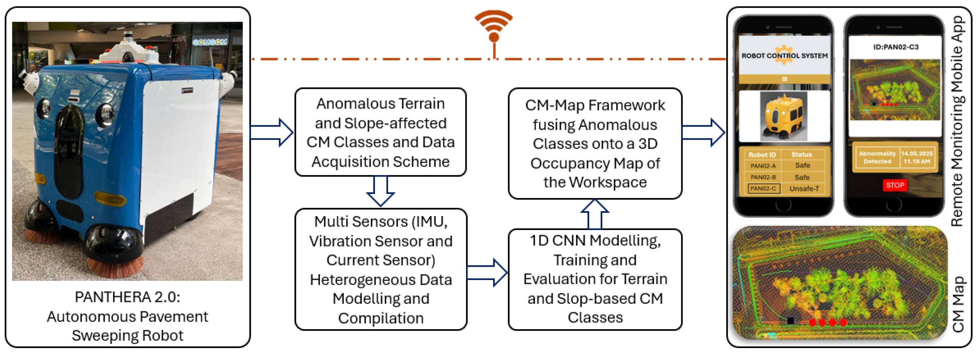
  • A novel condition monitoring (CM) framework is proposed, utilizing rotation, vibration, and current consumption data, specifically designed for large, heavy-duty outdoor pavement-sweeping robots considering the growing demand for urban hygiene.
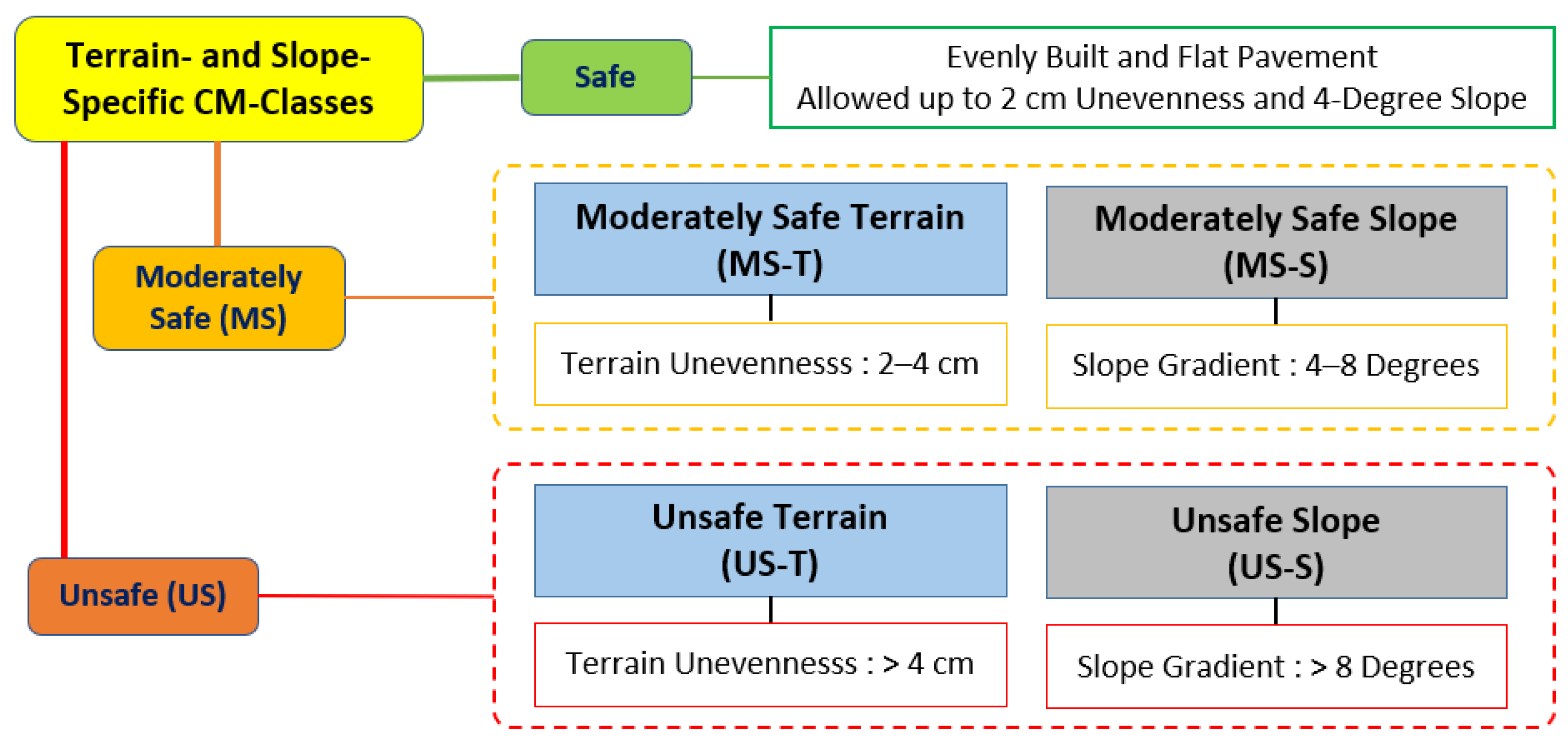
  • To ensure the robot’s health and operational safety under typical outdoor pavement challenges, such as uneven surfaces, unstructured grounds, and varying slopes, the study defines four distinct anomaly classes: moderately safe terrain, unsafe terrain, moderately safe slope, and unsafe slope.
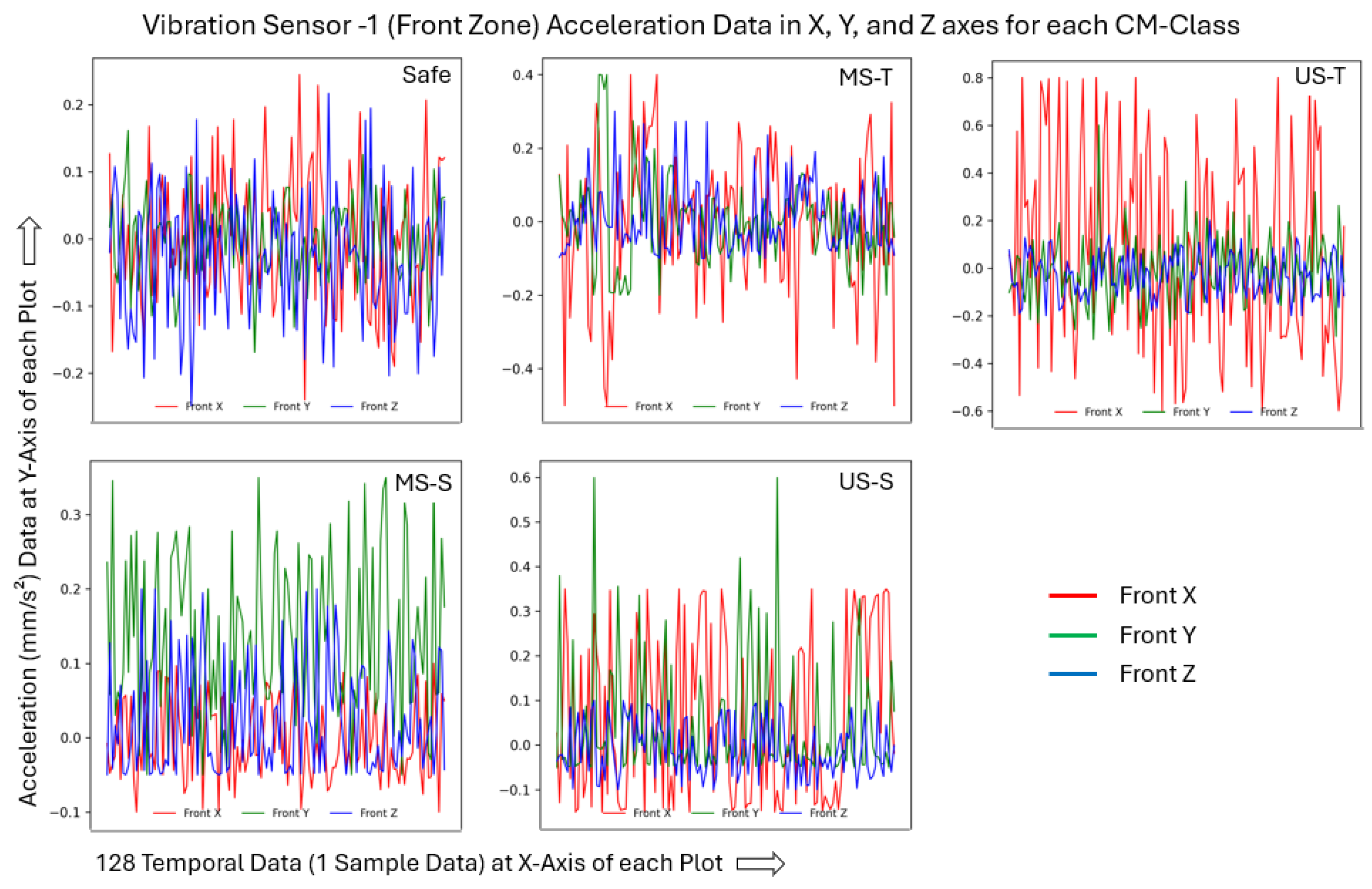
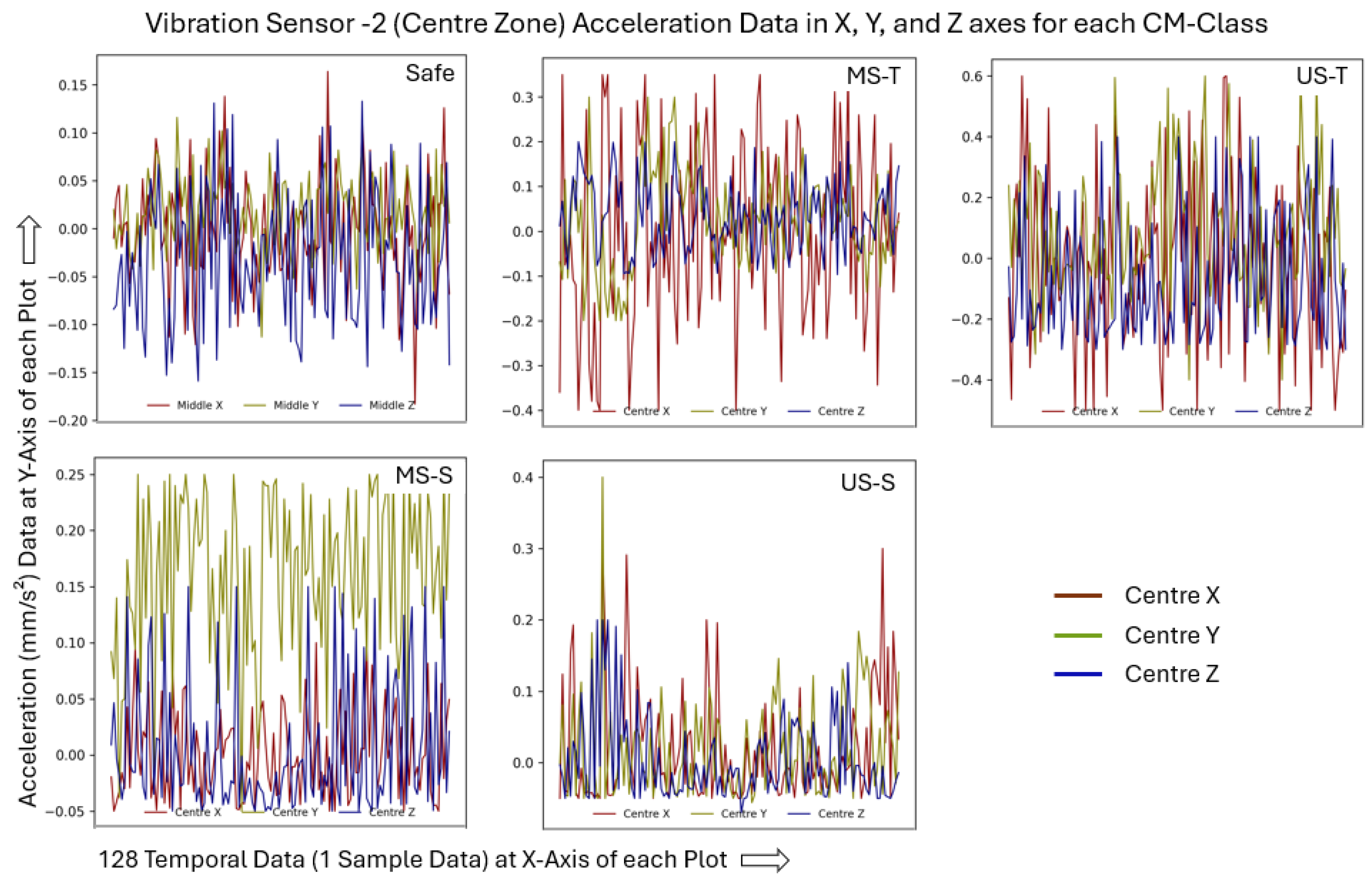
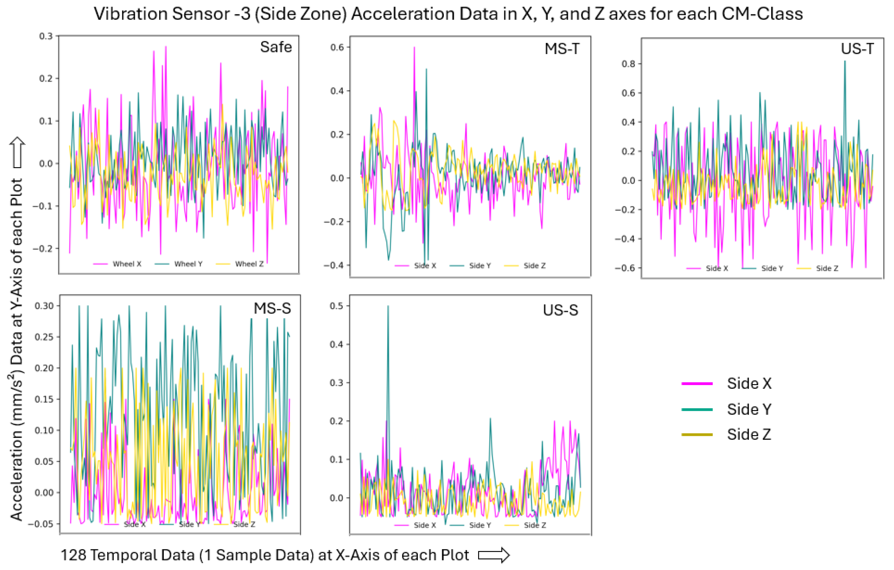
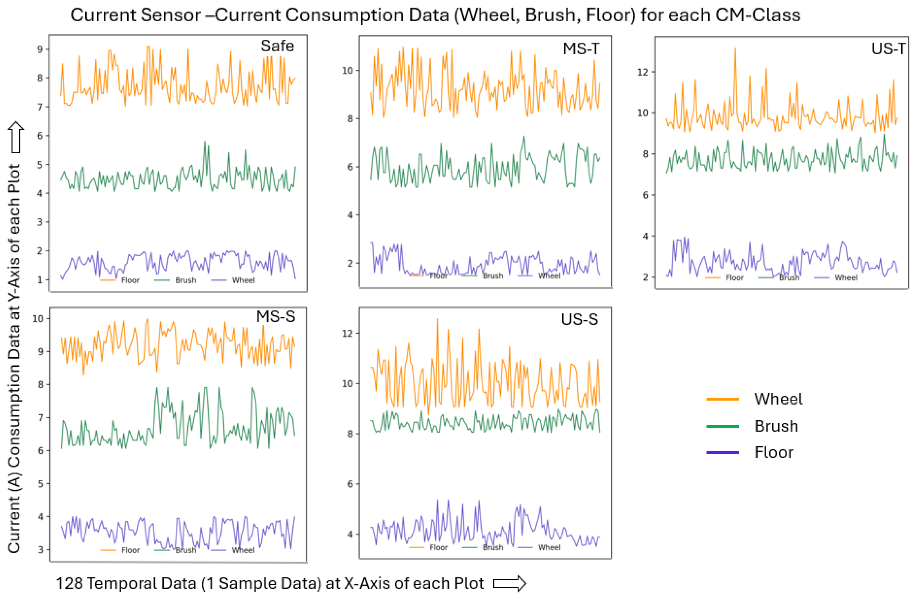
  • A comprehensive heterogeneous dataset is developed by integrating data from multiple sensors: an IMU capturing triaxial angular velocity (roll, pitch, yaw); three vibration sensors positioned in high-impact zones, measuring triaxial vibration acceleration; and current sensors collecting current consumption data from the side brush, floor tool, and drive wheel motors. This integration effectively enables the accurate modeling of both safe and anomalous classes within the CM framework.
  • A 1D CNN model is designed for efficient training and real-time classification, ensuring fast and reliable detection of anomalous states while maintaining low computational overhead.
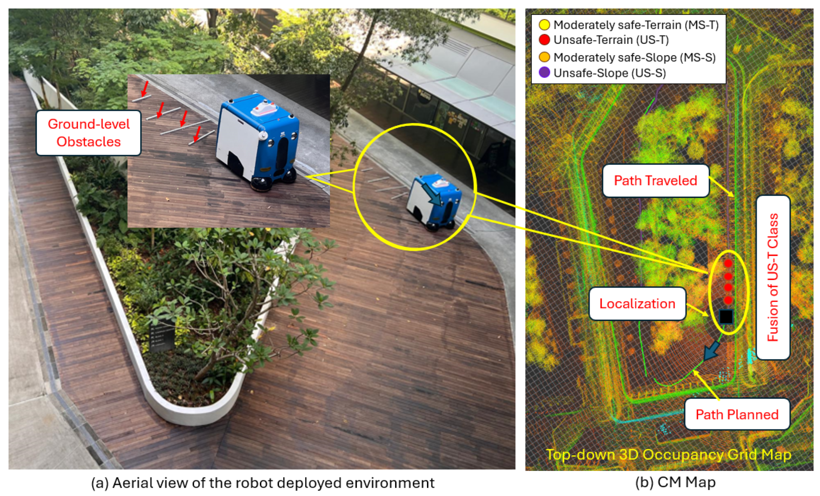
  • A CM-map framework is developed for real-time robot monitoring by overlaying predicted anomalous classes onto a 3D occupancy map of the workspace, enabling the maintenance team to take prompt action.
  • Based on case-study findings with the in-house-developed PANTHERA 2.0 robot, this study introduces a first-of-its-kind AI-driven, real-time CM framework that integrates multi-sensor heterogeneous data and incorporates slope as a new class of monitoring feature to enhance robotic health, operational safety, and support CBM in large-scale autonomous pavement-sweeping robots.
The rest of the paper is organized as follows: Section 2 provides an overview of the proposed framework explaining the pavement-sweeping robot used and methodologies developed in this work. Section 3 details the experimental setup and presents the results, including comparisons with previous works and various AI models. Section 4 discusses real-time field case studies demonstrating the practical application of the approach. Finally, Section 5 concludes the paper.

2. Overview of the Proposed CM Framework

Figure 1 presents an overview of the proposed Condition Monitoring (CM) framework, designed for real-time monitoring and prediction of moderately safe to unsafe conditions caused by uneven terrain and slope gradients, for large, heavy-duty autonomous pavement-sweeping robots. The framework is further elaborated in the following subsections, including details of the in-house developed robot, PANTHERA 2.0, which was used for data collection and experimentation, and the various methodologies developed for this CM framework.

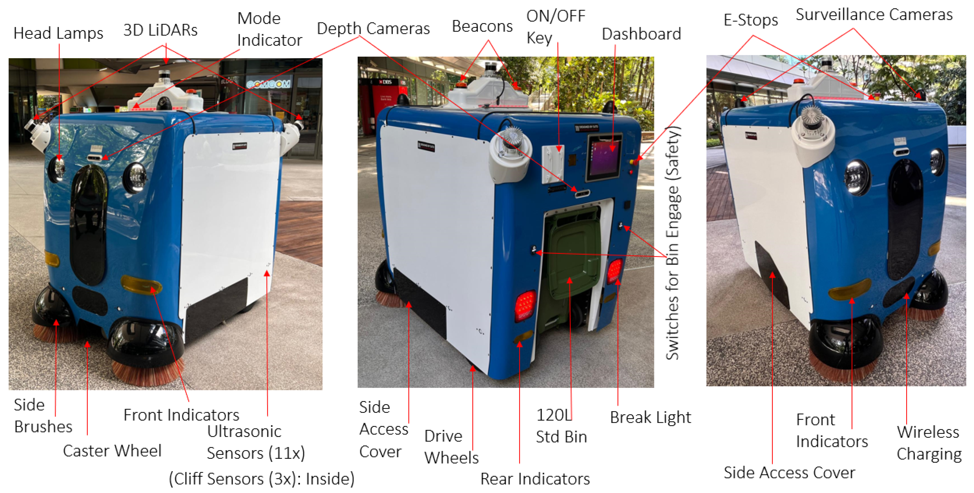
2.1. PANTHERA 2.0: A Heavy-Duty Outdoor Autonomous Robot for Pavement Sweeping

PANTHERA 2.0, an in-house-designed autonomous pavement-sweeping robot, was employed in the proposed terrain and slope-based condition monitoring study, which involves safe, moderately safe, and unsafe classifications and predictions to ensure the robot’s health and operational safety. It was used to collect data for each class to support 1D CNN model training, evaluation, and real-time field case studies. PANTHERA 2.0 represents a commercially available autonomous pavement-sweeping robot in terms of size, shape, capacity, and capabilities. Figure 2 depicts the robot’s appearance and the key components used. The overall dimensions of PANTHERA 2.0 are 1.9 m (L) × 1.3 m (W) × 1.8 m (H), with a weight of around 500 kg without the cleaning payload and 600 kg with the payload. The ruggedized chassis is constructed using welded stainless-steel hollow sections and plates, machined stainless-steel shafts, and aluminum brackets for mounting critical components. The outer cover is made of painted sheet metal, sealed with water- and dust-resistant gaskets. Additionally, easily accessible 3D-printed brush covers are included. All electromechanical and sensor assemblies are securely fastened to the metal chassis to ensure smooth and stable operation. A user-friendly dashboard with a Graphical User Interface (GUI) is integrated using a 12.1-inch LCD touchscreen for ease of control and monitoring. Two standard powered wheels, each with a diameter of 0.38 m and a width of 0.14 m, are mounted on a common rear axle. A heavy-duty caster wheel at the front provides additional stability. The drive mechanism is based on differential drive kinematics, enabling the robot to navigate typical pavement surfaces. Locomotion is powered by two 400 W motors (110 N·m torque) and two 150 Ah, 48 V Lithium Iron Phosphate (LFP) batteries, ensuring safe and effective movement. For autonomous navigation, PANTHERA 2.0 is equipped with two 3D LiDARs (32 planes) mounted diagonally for obstacle detection, one 3D LiDAR (128 planes) positioned at the center-top of the robot for localization, and two stereo cameras (front and rear) for object and lane detection. Twelve ultrasonic sensors are mounted around the robot for short-range object detection. Three cliff sensors are used to avoid cliffs on pavements. An Inertial Measurement Unit (IMU) is located at the center of the robot, and wheel encoders are used for dead reckoning. Additionally, two USB cameras mounted on top of the robot provide surveillance capabilities. The autonomy algorithms run on embedded PCs powered by Ubuntu 20.04 LTS and the Robot Operating System (ROS) middleware. PANTHERA 2.0 maintains a slow operating speed of 0.5 to 1.0 km/h to ensure effective sweeping performance, capable of collecting typical pavement debris such as dry and wet leaves, small branches, used cans, and plastic bottles. The robot is designed to handle slopes up to approximately eight degrees; however, continuous operation on slopes exceeding six degrees is not recommended to preserve motor and electromechanical component reliability over extended use. PANTHERA 2.0 is designed to ensure maximum safety during operation in real-world outdoor environments. It is equipped with emergency stop buttons at both the front and rear, headlights for low-light conditions, rear brake lights, left and right indicator lights mounted at both the front and rear, two beacon warning lights, and operational mode indicators. A standard 120 L bin with an automated engagement and safety mechanism is integrated for efficient accessory management, reduced manual trash disposal effort, and safer overall operation.

2.2. Terrain and Slope CM Classes for Health and Operational Safety of Pavement-Sweeping Robots

Outdoor wheeled mobile robots are typically designed with ruggedized features, taking into account their exposure to dynamically changing climatic conditions, in contrast to indoor mobile robots. However, as outlined in the problem statement, unavoidable terrain irregularities and slope gradients can still lead to accelerated wear and tear at both the component and system levels. The severity of these adverse features can result in various operational issues such as obstructed or wobbling wheels, punctures, worn-out brushes, loosened assemblies, disrupted wheel and brush contact, sensor misalignment, compromised traction and stability, reduced braking efficiency, increased power consumption, accelerated motor degradation, and an elevated risk of tipping. These challenges are particularly critical for pavement-sweeping robots, which are required to clean the entire pavement surface regardless of terrain or slope conditions. Therefore, it is essential to monitor and assess the severity of such anomalies during deployment to determine whether operating conditions fall within safe or unsafe limits. Given that uneven terrain and slope gradients directly affect the robot’s health and operational safety, this work introduces five CM classes to categorize these features: safe, moderately safe terrain (MS-T), unsafe terrain (US-T), moderately safe slope (MS-S), and unsafe slope (US-S), as illustrated in Figure 3. The “safe” class refers to smooth, flat terrain with a maximum deviation—either raised (positive obstacles) or recessed (negative obstacles)—of up to 2 cm and a slope gradient of up to 4 degrees, requiring no intervention. The “MS-T” class includes terrain with positive or negative irregularities ranging from 2 cm to 4 cm, while anything exceeding 4 cm falls into the “US-T” class. For slopes, gradients between 4 and 8 degrees are categorized as “MS-S”, and those exceeding 8 degrees as “US-S”. These quantitative criteria for each class are derived from real-world field tests and observations of abnormal behavior in the PANTHERA 2.0 robot. The “MS-T” and “MS-S” classes do not require immediate corrective action but should be closely monitored if operations in those areas are to continue over the long term. However, for the US-T and US-S classes, an immediate stop is recommended, and such areas should be avoided or rectified where possible.

2.3. Dataset Modeling for Terrain and Slope-Specific CM Classes

When a pavement-sweeping robot operates on uneven terrain or steep slopes—where its drive wheels, side brushes, and floor tools encounter positive or negative obstacles—it experiences abnormal vibrations and increased power consumption as it works to overcome these challenges. By analyzing vibration levels across three axes and monitoring power usage, the robot’s operational safety level—classified into the five CM classes described earlier—can be determined. Hence, to collect vibration- and power-consumption-affected data across five classes, a heterogeneous dataset collection and modeling framework was developed in this work. This framework primarily utilized three types of sensors. First, an IMU sensor (VectorNav VN-100) was mounted at the center of PANTHERA 2.0 to measure the platform’s rotational movement around its X, Y, and Z axes (roll, pitch, and yaw) resulting from uneven terrain and positive or negative ground-level obstacles on pavements. In large, heavy-duty pavement-sweeping robots like PANTHERA 2.0, aberrant vibrations often originate from various components or sub-assemblies that interact directly with the pavement, especially the sweeping payloads. These vibrations are transmitted throughout the robot’s structure. Therefore, three vibration-prone zones were identified: the front zone (housing the caster wheel and front brushes), the center zone (floor tool area, also reflecting overall vibration), and the side zone (near to the right-side drive wheel, including the suction assembly housing). In each of these zones, a triaxial vibration sensor (WitMotion WTVB02-485) was firmly mounted on the chassis. As discussed earlier, current consumption is a key indicator of slope gradients and obstacle-navigation scenarios. Accordingly, current sensors (AEAK DC 5V WCS1800 Hall current detection sensor module 35A) were installed to monitor power usage across all major motors, including those for the left and right drive wheels, left- and right-side brushes, and the floor tool. Figure 4 illustrates the sensor placements and the identified zones used to develop this dataset framework.
The types of data planned from each sensor, along with the data compilation process for training the 1D CNN-based model and enabling real-time prediction, were as follows: The IMU sensor mounted at the center of the robot collected three types of data—angular velocity (AngVel) along the X, Y, and Z axes. These values varied with the robot’s vibrations and determined its orientation in three-dimensional space, thus indicating the slope angle. Therefore, the IMU data reflected both abnormal vibrations and slope gradients. The WTVB02-485 vibration sensors, mounted at the three identified vibration-prone zones, measured vibration acceleration (VibAcc1 at the front, VibAcc2 at the center and VibAcc3 at the side zones) along the X, Y, and Z axes—providing a total of nine values. These data helped determine the level of vibration experienced by the robot due to uneven pavement and ground-level obstacles. Finally, the current sensors mounted on the power motors provided three values: the average current consumption of the left and right drive wheel (Wheel) motors, the average current consumption of the left- and right-side brush (Brush) motors, and the current consumption of the floor tool (Floor) motor. These three current readings indicated the robot’s exposure to slope gradients and ground-level obstacles. In total, fifteen features—comprising vibration and slope-related data—were used for each class to develop the dataset for the proposed CM framework. Each sensor collected data at a frequency of 50 Hz. One data sample was compiled from 128 temporal data points over a duration of 2.6 s, based on the robot’s operating speed and observed behavior. A window of 128 points provides sufficient context for learning meaningful patterns while balancing accuracy and computational efficiency. It is widely used in time series tasks, as larger windows may add complexity and risk overfitting. Empirical evidence supports 128 as a reliable window size that often delivers strong results [35,36,37,38]. A data collection and compilation algorithm was developed to generate one complete sample consisting of fifteen types of data and to create an array of [128 × 15] as expressed in (1) for 1D CNN training and prediction of CM classes.
A n g V e l ( X ) t 1 , A n g V e l ( X ) t 2 , A n g V e l ( X ) t 128 A n g V e l ( Y ) t 1 , A n g V e l ( Y ) t 2 , A n g V e l ( Y ) t 128 A n g V e l ( Z ) t 1 , A n g V e l ( Y ) t 2 , A n g V e l ( Z ) t 128 V i b A c c 1 ( X ) t 1 , V i b A c c 1 ( X ) t 2 , V i b A c c 1 ( X ) t 128 V i b A c c 1 ( Y ) t 1 , V i b A c c 1 ( Y ) t 2 , V i b A c c 1 ( Y ) t 128 V i b A c c 1 ( Z ) t 1 , V i b A c c 1 ( Z ) t 2 , V i b A c c 1 ( Z ) t 128 V i b A c c 2 ( X ) t 1 , V i b A c c 2 ( X ) t 2 , V i b A c c 2 ( X ) t 128 V i b A c c 2 ( Y ) t 1 , V i b A c c 2 ( Y ) t 2 , V i b A c c 2 ( Y ) t 128 V i b A c c 2 ( Z ) t 1 , V i b A c c 2 ( Z ) t 2 , V i b A c c 2 ( Z ) t 128 V i b A c c 3 ( X ) t 1 , V i b A c c 3 ( X ) t 2 , V i b A c c 3 ( X ) t 128 V i b A c c 3 ( Y ) t 1 , V i b A c c 3 ( Y ) t 2 , V i b A c c 3 ( Y ) t 128 V i b A c c 3 ( Z ) t 1 , V i b A c c 3 ( Z ) t 2 , V i b A c c 3 ( Z ) t 128 I ( W h e e l ) t 1 , I ( W h e e l ) t 2 , I ( W h e e l ) t 128 I ( B r u s h ) t 1 , I ( B r u s h ) t 2 , I ( B r u s h ) t 128 I ( F l o o r ) t 1 , I ( F l o o r ) t 2 , I ( F l o o r ) t 128

2.4. 1D Convolutional Neural Network Modeling for CM Classes

A solid understanding of deep learning and convolutional operations is crucial for selecting an appropriate classification model based on the nature of the input data. It is equally important when designing the model architecture—particularly the convolutional layers—to ensure high accuracy, fast processing, and suitability for real-time applications. Convolutional neural networks (CNNs) are well suited for processing various types of data, including 1D signals, 2D images, and 3D videos [39,40,41,42,43]. In this study, a 1D convolutional neural network (1D CNN) was employed to classify the safe to unsafe five CM classes and enable real-time prediction. This choice was motivated by the model’s simple structure, low computational cost, and superior performance demonstrated in our previous CM studies [29,30,31] compared to other AI-based models.
A four-layer 1D convolutional neural network (CNN) model was designed, operating based on convolutional operations applied to data vectors, as defined in Equations (2) and (3) [44]. In this model, an input vector x of length N is convolved with a filter vector ω of length L, along with a bias term b, to produce an output vector of length (NL + 1). A nonlinear activation function is applied to enhance the model’s learning capability. Following the convolutional layers, a max pooling layer is employed to extract the most significant features and reduce the number of parameters. In this context, m × 1 denotes the kernel size, u represents the pooling window function, and s is the stride length that determines the filter’s movement across the input vector c.
Output layer c ( j ) = f i = 0 L 1 ω ( i ) x ( j i ) + b , where , j = 0 , 1 , , N 1
Max Pooling output vector d = m a x u ( m × 1 , s ) c
The input vibration data used for training the 1D CNN model were organized into an array of dimensions [n × 128 × 15], where n represents the total number of samples. This dataset was then flattened into a 1D array of size [1 × 1920], which was one sample, before being fed into the 1D convolutional network. The model architecture was kept simple, consisting of four convolutional layers. The first two layers utilized 64 filters each, while the remaining two used 32 filters. All layers employed a kernel (convolution window) size of 3. To capture complex nonlinear patterns in the data collected from heterogeneous sensors, a Rectified Linear Unit (ReLU) activation function was applied after each convolutional layer. Each convolutional layer was followed by a max pooling layer with a stride of 2 to reduce computational load. Additionally, dropout layers with a dropout rate of 0.2 were incorporated after each convolutional layer to mitigate overfitting during training. Finally, the resulting pooled feature maps were flattened into a 1D array at the output layer, and a Softmax function was applied as the final activation function to enable the prediction of multinomial probabilities corresponding to different CM classes. The structure of the proposed 1D CNN model including the data shape is illustrated in Figure 5.

2.5. CM Map for Real-Time Monitoring

A mapping framework was developed to generate a CM Map, enabling real-time tracking of moderately safe and unsafe CM classes during the deployment of a pavement-sweeping robot. The process was executed in two main stages. First, a 3D occupancy grid map of the robot’s workspace was created using data from the onboard 3D LiDAR sensor and a Simultaneous Localization And Mapping (SLAM) system [45], implemented based on the HDL-graph-SLAM algorithm [46,47]. Next, a CM class mapping algorithm was developed. This algorithm identified and fused moderately safe and unsafe classes—those requiring attention or immediate action—onto the 3D occupancy grid map. Using the robot’s localization data, it tracked the robot’s position and overlaid the predicted CM class at the corresponding coordinates of the robot’s footprint. Each class was represented by a color-coded dot and timestamp. The CM map offered a top-down view, where classes were color-coded as follows: yellow for MS-T, orange for MS-S, red for US-T, and purple for US-S. Figure 6 illustrates the CM map, including a photo of the PANTHERA 2.0 robot operating on a pavement area, representing an instance of the US-T class. As the robot navigated on an uneven surface with ground-level obstacles of more than 4 cm in height, the CM-map framework identified and marked the US-T class on the 3D occupancy map at the corresponding locations. This CM-map system enables the maintenance team to monitor anomalous robot behavior resulting from workspace irregularities in real time via a mobile application, which is connected through the Message Queuing Telemetry Transport (MQTT) protocol. This facilitates prompt maintenance or corrective actions, thereby supporting a condition-based maintenance approach that improves system reliability, boosts productivity, and enhances operational safety.

3. Experiments and Results

This section details the setup for training data acquisition and visualization for each CM class, outlines the methodology used to train and evaluate the 1D CNN model, and presents the corresponding results and discussions.

3.1. Training Dataset Preparation and Visualization

In this study, the preparation of both qualitative and quantitative datasets that accurately represent real-world outdoor scenarios is essential for training and evaluating a 1D CNN model across various CM classes. To ensure realism, the PANTHERA 2.0 robot was operated at a speed of 0.7 km/h on typical pavements in sweeping mode, following both straight and zig-zag trajectories consistent with standard sweeping patterns. We ensured that all sensors were firmly mounted and set to a data collection frequency of 50 Hz.
For the safe class, data were collected while navigating well-maintained pavements that featured only minor surface irregularities, such as slight undulations, positive or negative obstacles less than 2 cm in height or depth, and mild slopes with inclinations of less than 4 degrees. For the MS-T classes, the robot was deployed in areas with visibly deteriorated pavements. These surfaces included ground-level anomalies with obstacle heights or depths ranging from 2 to 4 cm. Notable features encountered included surface cracks, uplifted sections caused by tree roots, manhole covers, utility access points, curbs, pavement edges, drainage grates, pits, gutters, steps, cliffs, exposed roots, and broken or missing paving elements. For the US-T class, the robot operated in environments containing more severe irregularities, with obstacle dimensions ranging from 4 to 8 cm. Further, data were collected on inclined surfaces: for the MS-S class, slopes ranged from 4 to 8 degrees, while for the US-S class, inclines ranged from 8 to 14 degrees. During these trials, notable mechanical responses were observed, such as significant vibrations while traversing uneven ground—particularly for the US-T class—along with incidents of power trips on steep slopes. The robot also experienced wheel punctures and a heightened risk of tipping over when negotiating pits and cliffs. Figure 7 illustrates the range of pavement features explored during data collection for each CM class.
For each CM class, a sample of 128 time series (temporal) data points was collected from each sensor and visualized to highlight CM-class-specific unique patterns. Figure 8 displays the angular velocity data along the X, Y, and Z axes from the IMU sensor. Figure 9, Figure 10 and Figure 11 present vibration acceleration data from three-axis for the vibration sensors mounted at front, center and side zones, respectively. Figure 12 shows current consumption readings from motors powering the drive wheels, side brushes, and floor tool.
To optimize convergence during 1D CNN training, all data x underwent normalization preprocessing. The IMU and vibration sensor readings were scaled to a range of −1 to +1, while the current sensor data were normalized between 0 and 1, using Equations (4) and (5), respectively. A total of 2500 samples per CM class [2500 × 128 × 15] were collected and split into 80% for training and 20% for validation. An additional 500 samples per class were recorded for model evaluation.
IMU and Vibration Sensor Dataset : x N o r m a l i s e d = 2 x m i n ( x ) m a x ( x ) m i n ( x ) 1
Current Sensor Dataset : x N o r m a l i s e d = x m i n ( x ) m a x ( x ) m i n ( x )

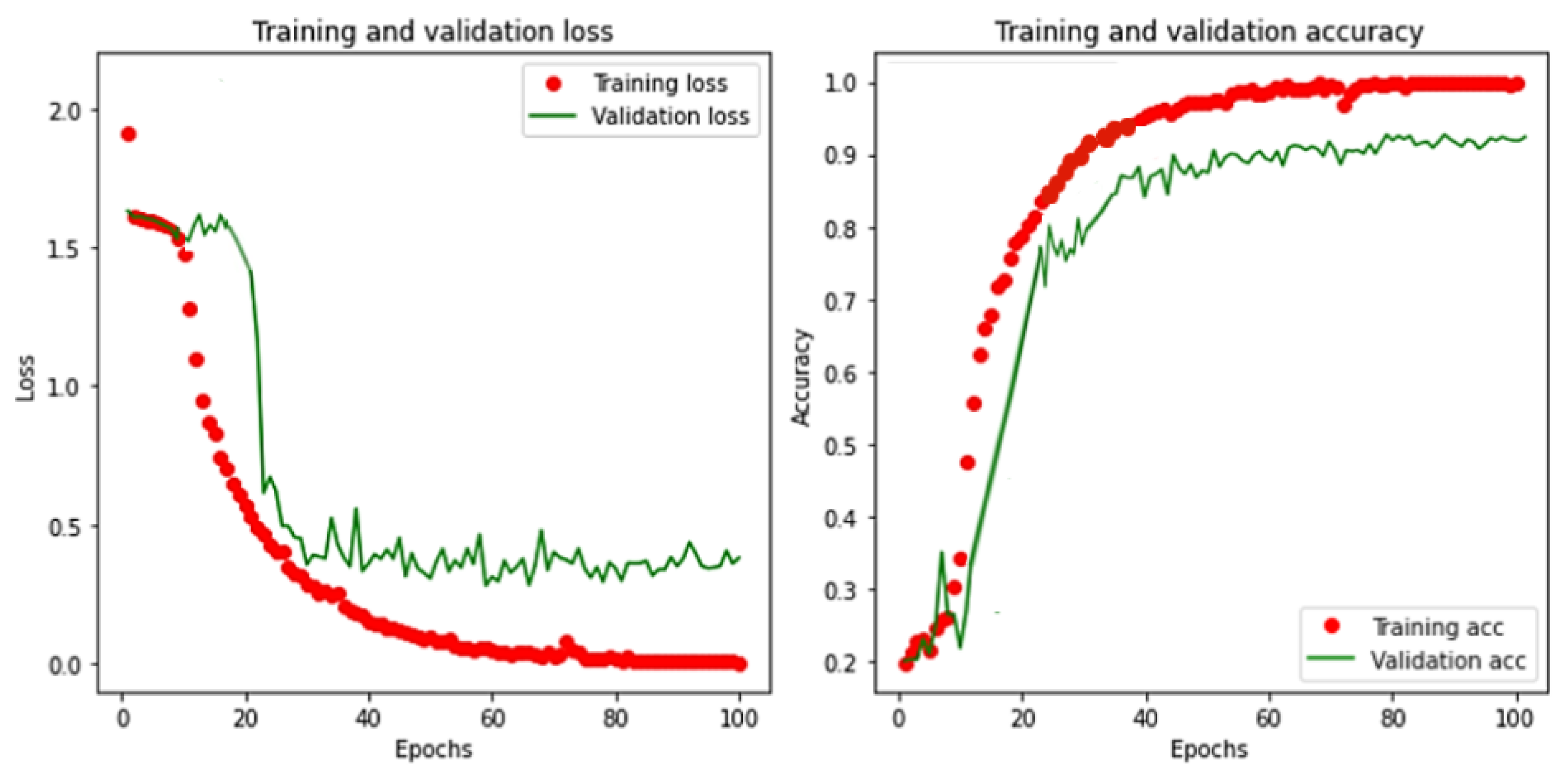
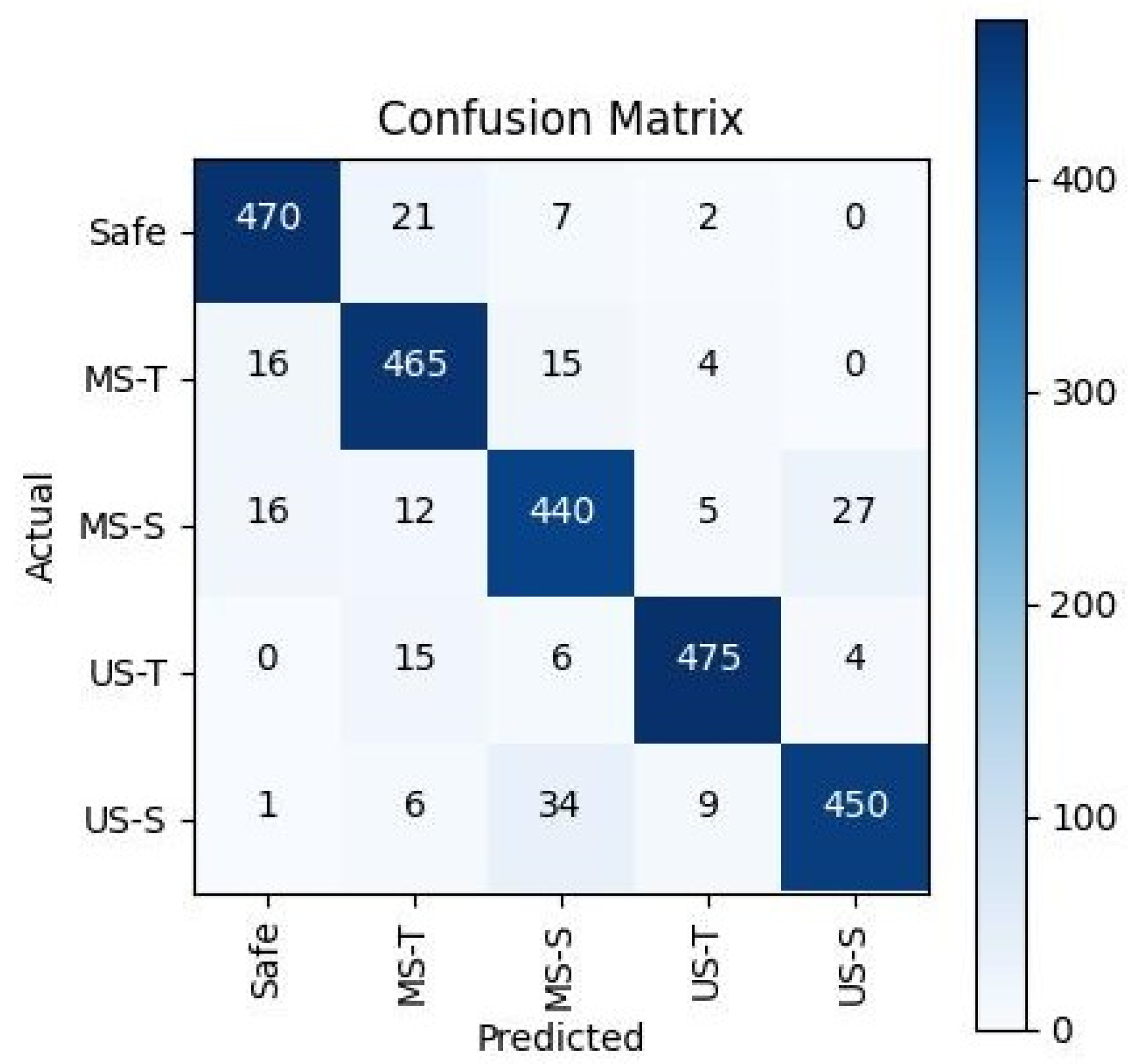
3.2. One-Dimensional CNN Model Training, Evaluation, and Comparison

A supervised learning approach was employed to train the proposed 1D CNN model using a custom heterogeneous-sensor dataset collected by our in-house-developed PANTHERA 2.0 autonomous pavement-sweeping robot. To enhance dataset reliability, prevent overfitting, and improve generalization, k-fold cross-validation was implemented. In this method, the data were split into five (k) subsets, with four used for training and one for evaluating the model’s performance in each iteration. The training process was carried out on a workstation equipped with an Nvidia GeForce GTX 1080 Ti GPU, utilizing the TensorFlow deep learning library [48]. To accelerate convergence and avoid local minima, a momentum-based gradient descent strategy was adopted. Specifically, the Adam optimizer [49] was used with a learning rate of 0.001, a first-moment exponential decay rate of 0.9, and a second-moment decay rate of 0.999. Categorical cross-entropy was chosen as the loss function to ensure minimal classification error. After experimentation with various configurations, the final training hyperparameters were set to a batch size of 32 and 100 epochs. Figure 13 illustrates the training and validation loss and accuracy curves. Next, the prediction accuracy of the 1D CNN model was evaluated using 500 unseen samples that were not part of the training process. The evaluation employed standard statistical metrics—Accuracy, Precision, Recall, and F1 Score—as defined in Equations (6)–(9) [50], based on the confusion matrix. In these equations, TP represents true positives, TN true negatives, FP false positives, and FN false negatives. The results of this offline evaluation are summarized in Table 1, showing an average accuracy of 92%. The approximate inference time for classifying a single sample was measured at 2.068 milliseconds. For class-wise analysis and visual interpretability, a confusion matrix plot generated as shown in Figure 14, summarizing the actual classes (ground truth from the dataset) and the predicted classes (as output by the model).
A c c u r a c y = T P + T N T P + F P + T N + F N
P r e c i s i o n = T P T P + F P
R e c a l l = T P T P + F N
F 1 S c o r e = 2 × P r e c i s i o n × R e c a l l P r e c i s i o n + R e c a l l
To further analyze the contribution of each sensor, we conducted additional training sessions by selectively removing one sensor at a time and evaluating the resulting performance. Three sensor combinations were tested: IMU with current sensors, IMU with vibration sensors, and vibration with current sensors. In all cases, the model did not converge effectively and yielded lower average accuracies of 83.8%, 79.4%, and 77.9%, respectively. These results highlight the complementary nature of the sensors used in this study and demonstrate how their combined input significantly enhances the model’s ability to detect terrain unevenness and slope-related anomalies with high accuracy. It was also observed that the proposed CM method, which utilized three heterogeneous data sources from climate-independent interoceptive sensors (IMU, vibration sensor, and current sensor), outperformed our exteroceptive sensor-based 3D LiDAR CM approach [32] for outdoor terrain-related CM classes. Specifically, in that work, the classification accuracies for the moderately safe and unsafe terrain classes were limited to 85% and 92%, respectively. Moreover, the previous method did not consider slope as a CM class, which is a critical factor for outdoor pavement-sweeping robots—especially when operating on surfaces such as golf-course pavements. Further, we also compared our approach with other terrain classification studies [12,15,51,52], where the prediction accuracy for terrain classes was found to be lower (less than 90%) than that of the proposed method. Hence, the proposed approach, which uses heterogeneous data collected from climate-independent interoceptive sensors, provides complementary information for accurate prediction of both terrain unevenness and slope gradients.
We also conducted a comparative study to evaluate the performance of the proposed 1D CNN model against other AI models—specifically SVM, MLP, LSTM, and CNN-LSTM—in terms of prediction accuracy and inference time. To ensure a fair comparison, all models were trained and evaluated using the same dataset and computing resources as the 1D CNN. MLP, LSTM, and CNN-LSTM models were implemented using the TensorFlow library, while the SVM model was developed using the Scikit-learn package. Except for the SVM, all models utilized the same key hyperparameters as the 1D CNN: the Adam optimizer, a learning rate of 0.001, and the categorical cross-entropy loss function. For the SVM model, the primary parameters were set to C = 100 and gamma = 0.01, using the Radial Basis Function (RBF) kernel. Table 2 presents the results, showing each model’s prediction accuracy (average across five classes, in %) and inference time per sample (in milliseconds). The comparison indicates that the choice of the optimal model depends on factors such as the application’s requirements, the nature of the data in each class, how the training data are prepared, and whether real-time prediction is necessary. Given these considerations, the 1D CNN model proves to be the most suitable choice for the proposed condition monitoring framework based on heterogeneous data from the three different sensors used.

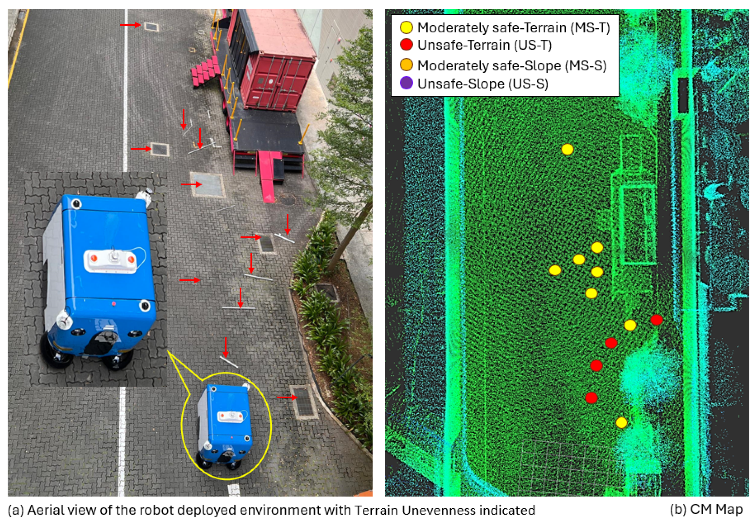
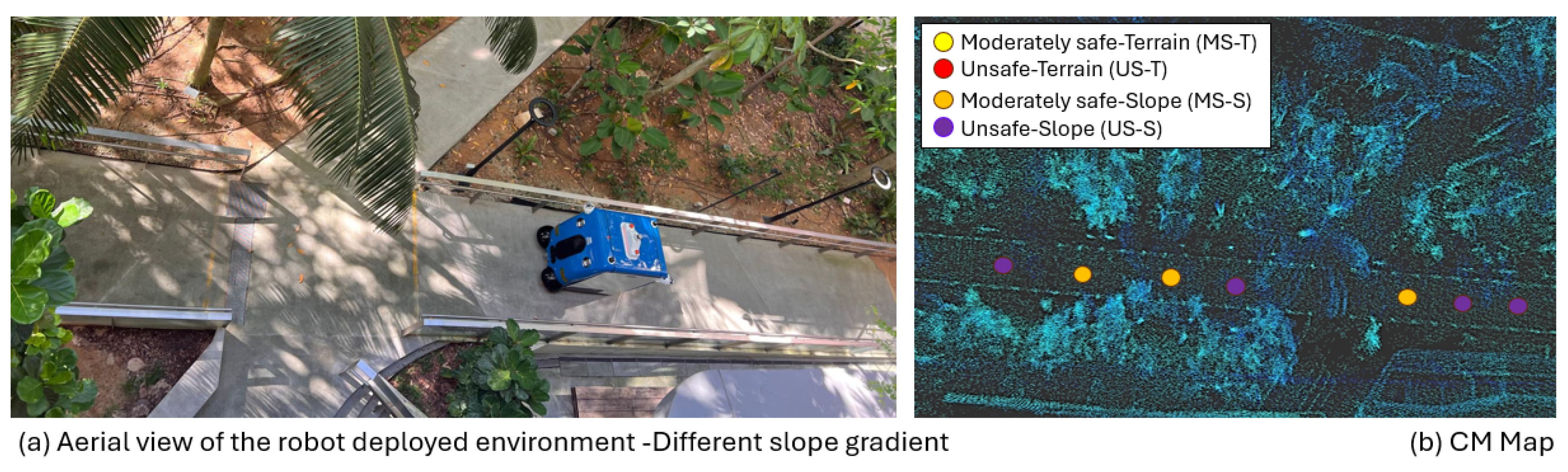
4. Real-Time Field Case Studies and Discussion

The proposed CM framework for an autonomous pavement-sweeping robot was validated through three real-time field case studies using the PANTHERA 2.0 robot. These trials were conducted in various outdoor locations across the SUTD campus, including a sloped area, to reflect real-world workspaces with diverse pavement characteristics. The selected test areas and ground-level obstacles introduced during these trials were different from those used during the training data acquisition phase, ensuring a robust and realistic validation. Before starting the trials, we ensured that the IMU, vibration, and current sensors were firmly mounted. Data were recorded at a sampling rate of 50 Hz, identical to that used during training. The robot’s operational health was confirmed prior to each trial, including verifying that the battery was fully charged. All tests were conducted in fully autonomous mode, with the robot moving at a consistent speed of 0.7 km/h in sweeping mode, following both straight and zigzag motion patterns to simulate realistic navigation and sweeping pattern scenarios.
Two algorithms were developed in preparation for these field trials. The first was a real-time inference engine designed to apply the trained 1D CNN model to new data samples as they were collected. As described in Algorithm 1, the engine processes 128 temporal data points (Data) across 15 sensor features (Feat) to form a [128 × 15] input matrix for the CNN model. A placeholder TBuffer accumulates the data, while the IBuffer stores the complete dataset for input into the model, which then predicts the corresponding CM class.
Algorithm 1 Inference engine
  • while  F e a t , D a t a are not empty do
  •      T B u f f e r = call S e n s o r ( F e a t , D a t a )
  •     Format T B u f f e r to have shape (15,128)
  •     Append T B u f f e r to I B u f f e r
  •      c o u n t e r F e a t = c o u n t e r F e a t + 1
  •      c o u n t e r D a t a = c o u n t e r D a t a + 1
  •     if  c o u n t e r F e a t = = 15 ,   c o u n t e r D a t a = = 128  then
  •          I n f e r r e d C l a s s = Call 1 D C N N ( I B u f f e r )
  •          c o u n t e r F e a t = 0
  •          c o u n t e r D a t a = 0
  •         Clean I B u f f e r
  •     end if
  • end while
Next, a 3D occupancy grid map was generated for each test area using a Cartographer SLAM-based approach. Building on this, a CM class mapping algorithm (Algorithm 2) was developed to track the robot’s position in real time and associate it with the predicted CM class (PCMC) from the inference engine. Each CM class prediction was marked at the center of the robot’s footprint (FP) on the map using a unique color and timestamp. This process produced a real-time CM map, visually representing the anomalous condition of the pavement encountered along the robot’s trajectory.
Algorithm 2 CM class mapping
  • P C [ M S T ,   M S S ,   U S T ,   U S S ]
  • m a p 2 D m a p
  • F P [ x , y ]
  • D T [ D a t e , T i m e ]
  • if  P C M C is Normal then  D o n o t h i n g
  • else if  P C M C is Abnormal then
  •     if  P C M C is MS-T then
  •          C o l o r Y e l l o w
  •     else if  P C M C is MS-S then
  •          C o l o r O r a n g e
  •     else if  P C M C is US-T then
  •          C o l o r R e d
  •     else if  P C M C is US-S then
  •          C o l o r P u r p l e
  •          m a p [ F P . x ] [ F P . y ] c o l o r
  •     end if
  • end if
  • s a v e M a p m a p , D T
The first case study was conducted on a uniformly tiled road connecting various buildings within the SUTD campus. An area of approximately 10 × 28 m2 was selected, which included several uneven and unstructured features such as missing or broken tiles, drainage covers at varying heights, curbs, small pits. Also, we introduced additional ground-level obstacles representing terrain related to the moderately safe (MS-T) and unsafe (US-T) classes. The robot was programmed to follow a predefined zig-zag path to ensure complete area coverage in a closed loop for the selected area for this case study. Localization was achieved using a pre-generated 3D LiDAR map in combination with the HDL-localization algorithm. As the robot traversed the area, it predicted MS-T and US-T terrain classes when encountering moderately safe and unsafe terrain features, respectively. These predictions and CM classes fused onto a real-time 3D occupancy grid map to generate the CM map were carried out using the inference engine and CM class mapping algorithms. During the test, the robot exhibited abnormal vibrations and was at risk of tipping over, particularly when encountering induced obstacles approximately 8 cm in height. It was also observed to deviate from its planned path and experienced sweeping power trips, especially during interactions with US-T features, likely due to surges from the floor tool motors. Figure 15 illustrates the deployment setup, the robot in operation, and the real-time CM map, where the MS-T class is indicated by yellow dots and the US-T class by red dots, as observed during case study 1.
The second case study was conducted on a long sloped pathway, 2.5 m in width, featuring varied gradient sections and several flat landing areas along the route. This sloped path, located within the SUTD campus, was constructed to provide wheelchair and bicycle access parallel to a log staircase connecting different campus levels. The PANTHERA 2.0 robot was deployed on this sloped pavement for several rounds of uphill and downhill traversal over a duration of 2 to 3 h, under the same operating conditions as described in the previous case study. The primary objective of this experiment was to evaluate the system’s consistency in predicting moderately safe (MS-S) and unsafe (US-S) slope conditions, as well as to observe their effects on the robot’s performance. Using Algorithms 1 and 2, along with a pre-mapped 3D occupancy grid of the environment, the system successfully identified and fused MS-S class predictions on slope areas with gradients ranging from 4 to 8 degrees, and US-S class predictions for slopes between 8 and 10 degrees. For safety reasons, slopes steeper than 10 degrees were excluded from autonomous trials. During the experiment, a power trip was observed once on the wheel motor while navigating a US-S classified area, which caused the robot to stop abruptly and placed strain on both the power and braking systems. Figure 16 illustrates the sloped environment used for case study 2, along with the CM map showing MS-S class markings in orange dots and US-S class markings in purple dots, highlighting the anomalous slope classifications encountered across the varying slope angles.
The third case study was conducted in an open-ground area which was paved with tiles. The site included existing features such as drainage manholes with raised covers and pits under maintenance. Additionally, a few ground-level obstacles of varied cross-sections were introduced to simulate moderately safe (MS-T) and unsafe (US-T) terrain classes. An area of approximately 12 × 20 m2 was selected, and the robot covered the full area using a zig-zag travel pattern. CM classes’ prediction and generating the CM map followed Algorithms 1 and 2, respectively. Moderately safe and unsafe terrain classes were predicted when the robot traversed uneven terrain spots or when ground-level obstacles were added. Figure 17 presents the test environment, the deployed PANTHERA 2.0 robot, and the corresponding CM map, with MS-T and US-T classes fused, as observed during case study 3.
To evaluate real-time prediction accuracy, we randomly collected 500 samples for each CM class from the three case studies, using ground-truth observations during the robot’s operation. The average prediction accuracy achieved was 90.8%, with class-wise accuracies detailed in Table 3. These results closely aligned with those from offline evaluations, thereby validating the feasibility and consistency of the proposed AI-enabled CM framework for real-time deployment in outdoor pavement-sweeping robots.
Beyond supporting maintenance reporting and corrective actions for robot-inclusive pavements, with consideration for the robot’s health and operational safety, the proposed CM framework offers additional value to robot deployment contractors. It enables an objective assessment of pavement suitability for long-term robotic operations by analyzing terrain- and slope-induced anomalous classes and their corresponding distributions (moderate and unsafe) through the generated CM map. This insight can help contractors refine their maintenance schedules and adjust deployment or rental strategies accordingly. To the best of our knowledge, such assessments are currently conducted manually—a process that is both labor-intensive and impractical, particularly given the dynamic nature of outdoor environments. Furthermore, this work can benefit robot manufacturers by informing improvements in design and mechanical assembly to match the varied pavement conditions, based on the types of terrain and slope conditions encountered during deployment. A notable advantage of the proposed CM framework is its exclusive use of interoceptive sensors, which ensures reliability regardless of external factors such as lighting, weather, or visibility—issues that commonly affect exteroceptive sensors like cameras or 3D LiDAR used for condition monitoring. Nonetheless, there remains room for improvement, particularly in enhancing prediction accuracy by incorporating additional relevant sensors for outdoor environments and accounting for system-generated vibrations caused by wear and tear during extended operation. These aspects are identified as key directions for our future work.

5. Conclusions

With the growing demand for autonomous pavement-sweeping robots driven by urbanization, hygiene requirements, and labor shortages, ensuring the operational safety and health of these systems in dynamic outdoor environments is critical. Despite their increasing use, there exists a research gap in effective condition monitoring (CM) specifically tailored to large, heavy-duty pavement-sweeping robots. This study addressed that gap by proposing and validating a novel AI-enabled CM framework that integrated multi-sensor heterogeneous data to classify pavement conditions, focusing on terrain unevenness and slope gradients. The framework employed angular motion, vibration, and current data to classify pavement conditions into five CM classes: safe, moderately safe terrain (MS-T), moderately safe slope (MS-S), unsafe terrain (US-T), and unsafe slope (US-S). To ensure reliable and climate-independent CM data collection, three interoceptive sensors—an IMU, vibration sensors, and current sensors—were used and tested on typical pavement environments, with their data complementing each other to enable accurate class prediction. A simple and computationally efficient four-layer 1D CNN model was developed and achieved an average prediction accuracy of 92% in evaluation and 90.8% in real-world case studies. A comparative analysis demonstrated that the proposed 1D CNN outperformed other AI models in both accuracy and computational efficiency, and surpassed our prior 3D LiDAR-based CM approaches for outdoor robots, as well as other existing terrain classification studies. Notably, this study was the first to introduce slope gradient as a parameter for CM in pavement-sweeping robots. Additionally, a CM-map framework was developed by fusing predicted anomalous classes with a 3D occupancy map of the pavement, enabling real-time robot monitoring and facilitating prompt maintenance interventions, assuring the robot’s health and operational safety. The study employed the in-house developed PANTHERA 2.0 robot, representative of commercial models, ensuring the direct applicability of the results to contract cleaning services and robot manufacturers for maintenance planning and resource optimization. For future work, we aim to enhance the prediction accuracy of the CM classes for pavement-sweeping robots by adding other relevant sensors for outdoor robots and also to include anomalous vibration due to system deterioration generated over continuous deployment. Future work will also focus on improving CM class prediction accuracy by incorporating additional relevant sensors suited for outdoor environments and accounting for anomalous vibrations caused by system deterioration over continuous use.

Author Contributions

Conceptualization, S.P. and M.R.E.; methodology, S.P. and M.A.V.J.M.; software, A.K.Z., A.J. and S.P.; validation, S.P., A.K.Z. and A.J.; formal analysis, S.P. and M.A.V.J.M.; investigation, S.P. and M.A.V.J.M.; resources, M.R.E.; data, S.P., A.K.Z. and A.J.; writing–original draft preparation, S.P.; supervision, M.R.E. and M.A.V.J.M.; project administration, M.R.E.; funding acquisition, M.R.E. All authors have read and agreed to the published version of the manuscript.

Funding

This research is supported by the National Robotics Programme under its National Robotics Programme (NRP) BAU, PANTHERA 2.0: Deployable Autonomous Pavement Sweeping Robot through Public Trials, Award No. M23NBK0065 and also supported by A*STAR under its RIE2025 IAF-PP programme, Modular Reconfigurable Mobile Robots (MR)2, Grant No. M24N2a0039.

Data Availability Statement

The data presented in this study are available on request from the corresponding author.

Conflicts of Interest

The authors declare no conflicts of interest.

References

  1. ABIResearch. Shipments of Outdoor Mobile Robots to 350,000 by 2030. Available online: https://www.abiresearch.com/press/labor-shortages-and-workplace-safety-concerns-propel-shipments-of-outdoor-mobile-robots-to-350000-by-2030/ (accessed on 10 January 2023).
  2. Zhang, F.S.; Ge, D.Y.; Song, J.; Xiang, W.J. Outdoor scene understanding of mobile robot via multi-sensor information fusion. J. Ind. Inf. Integr. 2022, 30, 100392. [Google Scholar] [CrossRef]
  3. Liang, Z.; Fang, T.; Dong, Z.; Li, J. An Accurate Visual Navigation Method for Wheeled Robot in Unstructured Outdoor Environment Based on Virtual Navigation Line. In Proceedings of the International Conference on Image, Vision and Intelligent Systems (ICIVIS 2021), Changsha, China, 18–20 June 2022; pp. 635–656. [Google Scholar]
  4. Yang, L.; Wang, L. A semantic SLAM-based dense mapping approach for large-scale dynamic outdoor environment. Measurement 2022, 204, 112001. [Google Scholar] [CrossRef]
  5. Dong, Y.; Liu, S.; Zhang, C.; Zhou, Q. Path Planning Research for Outdoor Mobile Robot. In Proceedings of the 2022 12th International Conference on CYBER Technology in Automation, Control, and Intelligent Systems (CYBER), Changbai Mountain, China, 27–31 July 2022; pp. 543–547. [Google Scholar]
  6. Liu, F.; Li, X.; Yuan, S.; Lan, W. Slip-aware motion estimation for off-road mobile robots via multi-innovation unscented Kalman filter. IEEE Access 2020, 8, 43482–43496. [Google Scholar] [CrossRef]
  7. Manikandan, N.; Kaliyaperumal, G. Collision avoidance approaches for autonomous mobile robots to tackle the problem of pedestrians roaming on campus road. Pattern Recognit. Lett. 2022, 160, 112–121. [Google Scholar] [CrossRef]
  8. Research, G.V. Outdoor Robot—Cleaning Robot Market Statistics. Available online: https://www.grandviewresearch.com/horizon/statistics/cleaning-robot-market/product/outdoor-robot/global/ (accessed on 10 December 2024).
  9. Ahmed, N.; Day, A.; Victory, J.; Zeall, L.; Young, B. Condition monitoring in the management of maintenance in a large scale precision CNC machining manufacturing facility. In Proceedings of the 2012 IEEE International Conference on Condition Monitoring and Diagnosis, Kitakyushu, Japan, 13–18 November 2012; pp. 842–845. [Google Scholar]
  10. Davies, A. Handbook of Condition Monitoring: Techniques and Methodology; Springer Science & Business Media: New York, NY, USA, 2012. [Google Scholar]
  11. Chng, G. Softbank Robotics Launches First Rent-a-Robot Offering for Cleaning Services in Singapore. Available online: https://www.techgoondu.com/2019/09/25/softbank-robotics-launches-first-rent-a-robot-offering-for-cleaning-services-in-singapore/ (accessed on 28 November 2021).
  12. Dupont, E.M.; Moore, C.A.; Collins, E.G.; Coyle, E. Frequency response method for terrain classification in autonomous ground vehicles. Auton. Robot. 2008, 24, 337–347. [Google Scholar] [CrossRef]
  13. Csík, D.; Odry, Á.; Sárosi, J.; Sarcevic, P. Inertial sensor-based outdoor terrain classification for wheeled mobile robots. In Proceedings of the 2021 IEEE 19th International Symposium on Intelligent Systems and Informatics (SISY), Subotica, Serbia, 16–18 September 2021; pp. 159–164. [Google Scholar]
  14. Khan, Y.N.; Komma, P.; Bohlmann, K.; Zell, A. Grid-based visual terrain classification for outdoor robots using local features. In Proceedings of the 2011 IEEE Symposium on Computational Intelligence in Vehicles and Transportation Systems (CIVTS) Proceedings, Paris, France, 11–15 April 2011; pp. 16–22. [Google Scholar]
  15. Weiss, C.; Tamimi, H.; Zell, A. A combination of vision-and vibration-based terrain classification. In Proceedings of the 2008 IEEE/RSJ International Conference on Intelligent Robots and Systems, Nice, France, 22–26 September 2008; pp. 2204–2209. [Google Scholar]
  16. Suger, B.; Steder, B.; Burgard, W. Traversability analysis for mobile robots in outdoor environments: A semi-supervised learning approach based on 3D-LIDAR data. In Proceedings of the 2015 IEEE International Conference on Robotics and Automation (ICRA), Seattle, WA, USA, 26–30 May 2015; pp. 3941–3946. [Google Scholar]
  17. Laible, S.; Khan, Y.N.; Bohlmann, K.; Zell, A. 3D LIDAR-and camera-based terrain classification under different lighting conditions. In Proceedings of the Autonomous Mobile Systems 2012: 22. Fachgespräch Stuttgart, Stuttgart, Germany, 26–28 September 2012; pp. 21–29. [Google Scholar]
  18. Janssens, O.; Slavkovikj, V.; Vervisch, B.; Stockman, K.; Loccufier, M.; Verstockt, S.; Van de Walle, R.; Van Hoecke, S. Convolutional neural network based fault detection for rotating machinery. J. Sound Vib. 2016, 377, 331–345. [Google Scholar] [CrossRef]
  19. Kumar, P.; Shankar Hati, A. Convolutional neural network with batch normalisation for fault detection in squirrel cage induction motor. IET Electr. Power Appl. 2021, 15, 39–50. [Google Scholar] [CrossRef]
  20. Abdeljaber, O.; Sassi, S.; Avci, O.; Kiranyaz, S.; Ibrahim, A.A.; Gabbouj, M. Fault detection and severity identification of ball bearings by online condition monitoring. IEEE Trans. Ind. Electron. 2018, 66, 8136–8147. [Google Scholar] [CrossRef]
  21. Kiranyaz, S.; Avci, O.; Abdeljaber, O.; Ince, T.; Gabbouj, M.; Inman, D.J. 1D convolutional neural networks and applications: A survey. Mech. Syst. Signal Process. 2021, 151, 107398. [Google Scholar] [CrossRef]
  22. Eren, L.; Ince, T.; Kiranyaz, S. A generic intelligent bearing fault diagnosis system using compact adaptive 1D CNN classifier. J. Signal Process. Syst. 2019, 91, 179–189. [Google Scholar] [CrossRef]
  23. Ince, T.; Kiranyaz, S.; Eren, L.; Askar, M.; Gabbouj, M. Real-time motor fault detection by 1-D convolutional neural networks. IEEE Trans. Ind. Electron. 2016, 63, 7067–7075. [Google Scholar] [CrossRef]
  24. Abdeljaber, O.; Avci, O.; Kiranyaz, S.; Gabbouj, M.; Inman, D.J. Real-time vibration-based structural damage detection using one-dimensional convolutional neural networks. J. Sound Vib. 2017, 388, 154–170. [Google Scholar] [CrossRef]
  25. Wang, J.; Wang, D.; Wang, X. Fault diagnosis of industrial robots based on multi-sensor information fusion and 1D convolutional neural network. In Proceedings of the 2020 39th Chinese Control Conference (CCC), Shenyang, China, 27–29 July 2020; pp. 3087–3091. [Google Scholar]
  26. Constantin, G.; Maroșan, I.A.; Crenganiș, M.; Botez, C.; Gîrjob, C.E.; Biriș, C.M.; Chicea, A.L.; Bârsan, A. Monitoring the Current Provided by a Hall Sensor Integrated in a Drive Wheel Module of a Mobile Robot. Machines 2023, 11, 385. [Google Scholar] [CrossRef]
  27. Rapalski, A.; Dudzik, S. Energy Consumption Analysis of the Selected Navigation Algorithms for Wheeled Mobile Robots. Energies 2023, 16, 1532. [Google Scholar] [CrossRef]
  28. Kryter, R.; Haynes, H. Condition Monitoring of Machinery Using Motor Current Signature Analysis; Technical Report; Oak Ridge National Lab.: Oak Ridge, TN, USA, 1989. [Google Scholar]
  29. Pookkuttath, S.; Rajesh Elara, M.; Sivanantham, V.; Ramalingam, B. AI-Enabled Predictive Maintenance Framework for Autonomous Mobile Cleaning Robots. Sensors 2022, 22, 13. [Google Scholar] [CrossRef] [PubMed]
  30. Pookkuttath, S.; Gomez, B.F.; Elara, M.R.; Thejus, P. An optical flow-based method for condition-based maintenance and operational safety in autonomous cleaning robots. Expert Syst. Appl. 2023, 222, 119802. [Google Scholar] [CrossRef]
  31. Pookkuttath, S.; Veerajagadheswar, P.; Rajesh Elara, M. AI-Enabled Condition Monitoring Framework for Indoor Mobile Cleaning Robots. Mathematics 2023, 11, 3682. [Google Scholar] [CrossRef]
  32. Pookkuttath, S.; Palanisamy, P.A.; Elara, M.R. AI-Enabled Condition Monitoring Framework for Outdoor Mobile Robots Using 3D LiDAR Sensor. Mathematics 2023, 11, 3594. [Google Scholar] [CrossRef]
  33. Pookkuttath, S.; Abdulkader, R.E.; Elara, M.R.; Veerajagadheswar, P. AI-Enabled Vibrotactile Feedback-Based Condition Monitoring Framework for Outdoor Mobile Robots. Mathematics 2023, 11, 3804. [Google Scholar] [CrossRef]
  34. Pookkuttath, S.; Gomez, B.F.; Elara, M.R. RL-Based Vibration-Aware Path Planning for Mobile Robots’ Health and Safety. Mathematics 2025, 13, 913. [Google Scholar] [CrossRef]
  35. Reza, S.; Ferreira, M.C.; Machado, J.J.; Tavares, J.M.R. Traffic state prediction using one-dimensional convolution neural networks and long short-term memory. Appl. Sci. 2022, 12, 5149. [Google Scholar] [CrossRef]
  36. Shrestha, A.; Dang, J. Deep learning-based real-time auto classification of smartphone measured bridge vibration data. Sensors 2020, 20, 2710. [Google Scholar] [CrossRef] [PubMed]
  37. Jiang, W. Time series classification: Nearest neighbor versus deep learning models. SN Appl. Sci. 2020, 2, 721. [Google Scholar] [CrossRef]
  38. Senjoba, L.; Sasaki, J.; Kosugi, Y.; Toriya, H.; Hisada, M.; Kawamura, Y. One-dimensional convolutional neural network for drill bit failure detection in rotary percussion drilling. Mining 2021, 1, 297–314. [Google Scholar] [CrossRef]
  39. Zhang, W.; Yang, G.; Lin, Y.; Ji, C.; Gupta, M.M. On Definition of Deep Learning. In Proceedings of the 2018 World Automation Congress (WAC), Stevenson, WA, USA, 3–6 June 2018; pp. 1–5. [Google Scholar] [CrossRef]
  40. LeCun, Y.; Bengio, Y.; Hinton, G. Deep learning. Nature 2015, 521, 436–444. [Google Scholar] [CrossRef]
  41. Albawi, S.; Mohammed, T.A.; Al-Zawi, S. Understanding of a convolutional neural network. In Proceedings of the 2017 International Conference on Engineering and Technology (ICET), Antalya, Turkey, 21–23 August 2017; pp. 1–6. [Google Scholar]
  42. Kiranyaz, S.; Ince, T.; Abdeljaber, O.; Avci, O.; Gabbouj, M. 1-D convolutional neural networks for signal processing applications. In Proceedings of the ICASSP 2019—2019 IEEE International Conference on Acoustics, Speech and Signal Processing (ICASSP), Brighton, UK, 12–17 May 2019; pp. 8360–8364. [Google Scholar]
  43. Chen, S.; Yu, J.; Wang, S. One-dimensional convolutional auto-encoder-based feature learning for fault diagnosis of multivariate processes. J. Process Control 2020, 87, 54–67. [Google Scholar] [CrossRef]
  44. Mitiche, I.; Nesbitt, A.; Conner, S.; Boreham, P.; Morison, G. 1D-CNN based real-time fault detection system for power asset diagnostics. IET Gener. Transm. Distrib. 2020, 14, 5766–5773. [Google Scholar] [CrossRef]
  45. Hess, W.; Kohler, D.; Rapp, H.; Andor, D. Real-time loop closure in 2D LIDAR SLAM. In Proceedings of the 2016 IEEE International Conference on Robotics and Automation (ICRA), Stockholm, Sweden, 16–21 May 2016; pp. 1271–1278. [Google Scholar]
  46. Koide, K.; Miura, J.; Menegatti, E. A portable three-dimensional LIDAR-based system for long-term and wide-area people behavior measurement. Int. J. Adv. Robot. Syst. 2019, 16, 1729881419841532. [Google Scholar] [CrossRef]
  47. Koide, K. HDL-Graph-SLAM Algorithm. Available online: https://github.com/koide3/hdl_graph_slam (accessed on 10 August 2022).
  48. Abadi, M.; Barham, P.; Chen, J.; Chen, Z.; Davis, A.; Dean, J.; Devin, M.; Ghemawat, S.; Irving, G.; Isard, M.; et al. Tensorflow: A system for large-scale machine learning. In Proceedings of the 12th USENIX Symposium on Operating Systems Design and Implementation, Savannah, GA, USA, 2–4 November 2016; Volume 16, pp. 265–283. [Google Scholar]
  49. Kingma, D.P.; Ba, J. Adam: A method for stochastic optimization. arXiv 2014, arXiv:1412.6980. [Google Scholar]
  50. Grandini, M.; Bagli, E.; Visani, G. Metrics for multi-class classification: An overview. arXiv 2020, arXiv:2008.05756. [Google Scholar] [CrossRef]
  51. Wang, M.; Ye, L.; Sun, X. Adaptive online terrain classification method for mobile robot based on vibration signals. Int. J. Adv. Robot. Syst. 2021, 18, 17298814211062035. [Google Scholar] [CrossRef]
  52. Tick, D.; Rahman, T.; Busso, C.; Gans, N. Indoor robotic terrain classification via angular velocity based hierarchical classifier selection. In Proceedings of the 2012 IEEE International Conference on Robotics and Automation, St. Paul, MN, USA, 14–18 May 2012; pp. 3594–3600. [Google Scholar]
Figure 1. Overview of the proposed CM framework for pavement-sweeping robots.
Mathematics 13 02306 g001
Figure 2. PANTHERA 2.0: an autonomous pavement-sweeping robot.
Mathematics 13 02306 g002
Figure 3. Terrain and slope-specific CM classes for pavement-sweeping robots.
Mathematics 13 02306 g003
Figure 4. Dataset acquisition scheme with heterogeneous sensors.
Mathematics 13 02306 g004
Figure 5. One-dimensional CNN structure and data shape modeled for training CM classes.
Mathematics 13 02306 g005
Figure 6. CM map: fusion of anomalous classes on 3D occupancy map.
Mathematics 13 02306 g006
Figure 7. Pavement features used for data acquisition of CM classes.
Mathematics 13 02306 g007
Figure 8. IMU sensor data for each CM class.
Mathematics 13 02306 g008
Figure 9. Vibration sensor-1 (front zone) data for each CM class.
Mathematics 13 02306 g009
Figure 10. Vibration sensor-2 (center zone) data for each CM class.
Mathematics 13 02306 g010
Figure 11. Vibration sensor-3 (side zone) data for each CM class.
Mathematics 13 02306 g011
Figure 12. Current sensors’ data for each CM class.
Mathematics 13 02306 g012
Figure 13. Training and validation loss and accuracy curves.
Mathematics 13 02306 g013
Figure 14. Confusion matrix based on evaluation dataset.
Mathematics 13 02306 g014
Figure 15. Case study 1: Anomalous terrain features prediction and CM map.
Mathematics 13 02306 g015
Figure 16. Case study 2: Anomalous slope features prediction and CM map.
Mathematics 13 02306 g016
Figure 17. Case study 3: Anomalous terrain features prediction and CM map.
Mathematics 13 02306 g017
Table 1. One-dimensional CNN model evaluation results based on three heterogeneous datasets.
Vibration ClassPrecisionRecallF1 ScoreAccuracy
Safe0.940.920.950.94
MS-T0.920.910.940.93
MS-S0.860.900.870.88
US-T0.930.960.940.95
US-S0.900.930.880.90
Table 2. Comparison with other AI models.
ModelAccuracy (%)Inference Time (ms)
1D CNN92.02.068
CNN-LSTM90.35.206
LSTM86.54.617
MLP82.33.845
SVM80.618.421
Table 3. Real-time prediction accuracy of CM classes.
CM ClassSafeMS-TMS-SUS-TUS-S
Accuracy Prediction (%)9391889389
Disclaimer/Publisher’s Note: The statements, opinions and data contained in all publications are solely those of the individual author(s) and contributor(s) and not of MDPI and/or the editor(s). MDPI and/or the editor(s) disclaim responsibility for any injury to people or property resulting from any ideas, methods, instructions or products referred to in the content.

