Abstract
Aiming at the formation problem of the multi-rotor UAV swarm, this paper adopts a multi-rotor UAV swarm formation control method based on a stress matrix to ensure the stability of multi-rotor UAV swarm formation. On the basis of achieving the target formation through a stress matrix, the formation of a multi-rotor UAV swarm can be rotated, scaled, and sheared. When the obstacles are known, the multi-rotor UAV swarm can pass through the obstacle environment smoothly through rotation, scaling, and shearing transformations. However, this transformation cannot cope with the situation where the obstacles are known. This paper proposes an active obstacle avoidance function for multi-rotor UAV swarm formation based on a stress matrix. Through the detection capability of the UAV itself, the obstacle avoidance function is realized autonomously after the UAV detects an unknown obstacle. Due to the effect of a stress matrix, when the navigator performs the active obstacle avoidance function, the formation of the multi-rotor UAV swarm will be destroyed. This paper designs a virtual UAV and only retains the UAV that controls the flight trajectory of the multi-rotor UAV swarm as the only real UAV to ensure that the UAV swarm formation is not destroyed. This paper proves the stability of the multi-rotor UAV swarm formation through simulation experiments, and the multi-rotor UAV swarm can pass through the obstacle environment smoothly when facing known obstacles and unknown obstacles.
Keywords:
multi-rotor UAV swarm; stress matrix; active obstacle avoidance; unknown environment; virtual UAVs MSC:
93C85
1. Introduction
In recent years, drones have been widely used in environmental detection, atmospheric research, disaster monitoring, aerial mapping, and other fields due to their simple structure, low cost, high reliability, and rapid maneuverability [1]. With the increase in application scenarios and the increase in demand, the coverage of a single drone is limited, the efficiency could be higher, and it is not easy to perform complex tasks [2]. Therefore, the coordinated control of multiple drone formations has become the focus of scientific researchers. Drone swarms mainly achieve combat missions through formation flying and perform formation generation, formation maintenance, formation change, and formation obstacle avoidance according to the expected instructions to meet diverse mission requirements [3,4].
Multi-rotor UAV swarm formation control technology is the core of multi-rotor UAV swarm formation to achieve coordinated and stable flight. The main control methods include the leader–follower method [5,6], behavior method [7,8], virtual structure method [9,10], consistency method [11,12], etc. The control strategy based on the leader–follower method is simple to operate and has strong feasibility, but it needs to be more robust. If the leader fails, the entire formation cannot be maintained, and it will cause large deviations when tracking a high-maneuverability leader. The control strategy based on the behavior method can effectively integrate multiple behavior modes, such as formation maintenance and obstacle avoidance. However, the model is highly complex, and the formation flexibility and adaptability must be improved. The formation control based on the virtual structure method is highly accurate and robust. However, reliability could be better guaranteed due to the large amount of communication and calculation caused by introducing the virtual structure. Consistency theory is the critical research content of multi-rotor UAV swarm system formation control and the basis of many formation control problems. Its basic idea is to build a distributed control protocol based on the local information interaction between adjacent UAVs to control the state variables required for cluster collaborative tasks to reach a consensus. The control technology of multi-rotor UAV swarm formation is divided into two categories according to different coordination strategies: centralized and distributed [3,13,14]. Among them, the main goal of distributed formation control is to design control methods using only local information to achieve a given formation shape. Current research mainly uses displacement, distance, and azimuth as state variables [15,16,17]. Displacement-based formation control methods are widely used to track target formations in linear motion, but constraints must be changed when dealing with deformation and change-of-direction formations. Distance-based control methods can be used to track target formations with time-varying translation and direction, but it takes work to track time-varying formation scales. Azimuth-based control methods can track formations with time-varying translation and scale, but it is challenging to track change-of-direction formations.
Many research teams have recently proposed using new state variables such as the center of gravity, complex Laplace, and stress matrix [18,19,20] to define target formations. For example, Lin [21] introduced stress matrix as a state variable in multi-agent system control and proved the mathematical conditions for affine formation. Zhao [22] proposed an affine formation maneuver controller based on a stress matrix, which implemented various maneuvers such as translation, rotation, scaling, and even shape deformation of the target formation. On this basis, Xu [23] studied the distributed formation maneuver control problem of high-order multi-agent systems with arbitrary dimensional directed networks. A high-order continuous polynomial can represent the leader trajectory. Yang [24] used the stress matrix under the universal rigid framework and considered pre-inputting the required formation size to only one agent. They proposed using a distributed estimator to calculate the scaling parameters of the remaining agents so that the formation can converge to the specified shape with the desired scaling amount. However, most of the formations in the above literature are planned by combining multiple leaders to calculate the route in the presence of known obstacles. They do not consider the existence of unknown obstacles and possible external interference, which cannot meet the actual task requirements.
A multi-rotor drone swarm may encounter obstacles during flight. Obstacles can be divided into known obstacles and unknown obstacles. A multi-rotor drone swarm can avoid known obstacles in advance through planning [25]. However, in the face of unknown obstacles, it is necessary to add an active obstacle avoidance function to the multi-rotor drone swarm to ensure that it does not collide with obstacles [26,27].
Formation control in multi-rotor UAV swarm systems refers to the coordination and control strategies used to form, maintain, and transform formations between UAVs. In situations where obstacles are dense or space is narrow, active sensing systems are utilized to improve the obstacle avoidance capabilities of multi-rotor UAV swarms [26], where UAV formations need to adapt and reconfigure their shape to pass through or around obstacles [28,29], ensuring that UAVs can fly safely in environments where unknown obstacles are present [27,30]. This self-reconfiguration capability allows UAVs to overcome challenging terrain, narrow passages, or complex structures, thus enhancing their maneuverability and overall mission success.
Coping with unknown obstacles and possible external interference allows multi-rotor UAV swarms to avoid obstacles [31,32,33] actively. Suppose a single UAV in the pilot UAV carries out active obstacle avoidance. In that case, the route planned by the original multi-rotor UAV swarm will be destroyed due to the effect of the stress matrix, so it is proposed to change the original multiple pilot UAVs to a single pilot UAV, and according to the position of this single UAV and the actual needs of the calculation of the position to obtain the position of the virtual UAVs, the virtual UAVs will not change their position due to the implementation of active obstacle avoidance function to ensure the stability of the formation. A single physical UAV and other virtual UAVs form a pilot multi-rotor UAV swarm to change the route and formation of the multi-rotor UAV swarm.
Based on the above analysis, this paper considers the problem of multi-rotor UAV swarm formation and obstacle avoidance control in an obstacle-unknown environment and designs an active obstacle avoidance function based on a stress matrix for a multi-rotor UAV swarm. Compared with the existing research results, the innovativeness of the work in this paper is as follows:
- (1)
- Consider the existence of unknown obstacles as external interference to increase the function of multi-rotor UAV swarm active obstacle avoidance. Multi-rotor UAV swarms in unknown environments and stress matrix-based multi-rotor UAV swarms use their detection ability to avoid unknown obstacles.
- (2)
- Design the virtual UAV as an auxiliary computational node to cooperate with the actual pilot UAV; the pilot UAV is only the first multi-rotor UAV swarm as the real UAV, and the other pilot UAVs are the virtual UAVs as the auxiliary computational nodes. This ensures the stability of the formation of the multi-rotor UAV swarm based on the stress matrix when encountering unknown obstacles.
In this paper, the first chapter introduces the current research status of the formation and obstacle avoidance problems of multi-rotor drone clusters. According to the current research status, the corresponding problems and methods are proposed. This chapter proposes the design of the active obstacle avoidance function of the multi-rotor drone cluster based on the stress matrix and designs the virtual drone as an auxiliary computing node to ensure the stability of the target formation of the multi-rotor drone cluster. Section 2 introduces the dynamic model of the multi-rotor drone cluster and the relevant introduction of the stress matrix. This chapter introduces the common classification of multi-rotor drones and specifically introduces the dynamic model of quadcopters. This chapter also introduces the relevant content of the stress matrix. Section 3 specifically introduces the active obstacle avoidance function of the multi-rotor drone cluster and the design of the virtual drone. The active obstacle avoidance function includes the active obstacle avoidance of the multi-rotor drone when it detects obstacles and the collision avoidance function between multi-rotor drones. The design of the virtual drone mainly includes the feasibility analysis of the virtual drone. Section 4 introduces the design of the control law of the experiment in this paper. This chapter includes the formation control law between the pilot drone and the virtual drone and the formation control law between the pilot drone and the follower drone. The formation control law between the pilot drone and the follower drone can be divided into three categories: the pilot is stationary, the pilot is at uniform speed, and the pilot is at variable speed. In Section 5, simulation experiments were conducted to verify the stability of the formation on the formation control effect of a multi-rotor UAV cluster based on a stress matrix. For unknown obstacles, experiments on single-sided and double-sided obstacles proved the reliability of the active obstacle avoidance function of the multi-rotor UAV cluster. For known obstacles, the reliability of obstacle avoidance by formation transformation of the multi-rotor UAV cluster was proved. The simulation verification of obstacle avoidance of the multi-rotor UAV cluster was carried out through RflySim. Section 6 summarizes the formation capability and obstacle avoidance function of the multi-rotor UAV cluster and points out the limitations of this article and future research directions.
2. Dynamic Model and Preliminary Knowledge
2.1. Dynamic Model
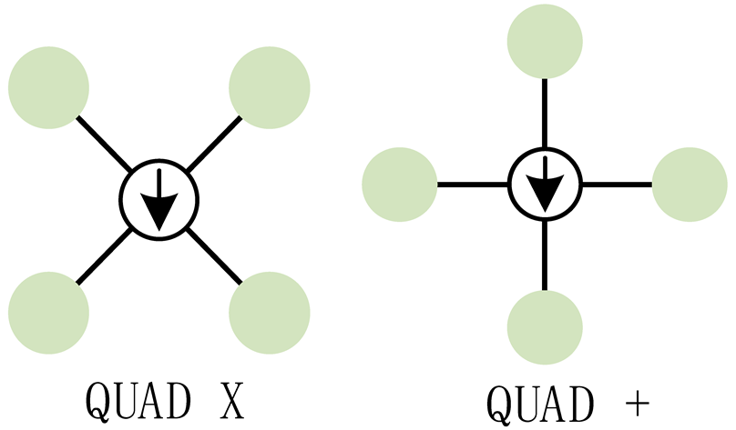
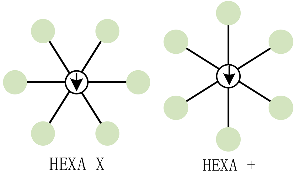
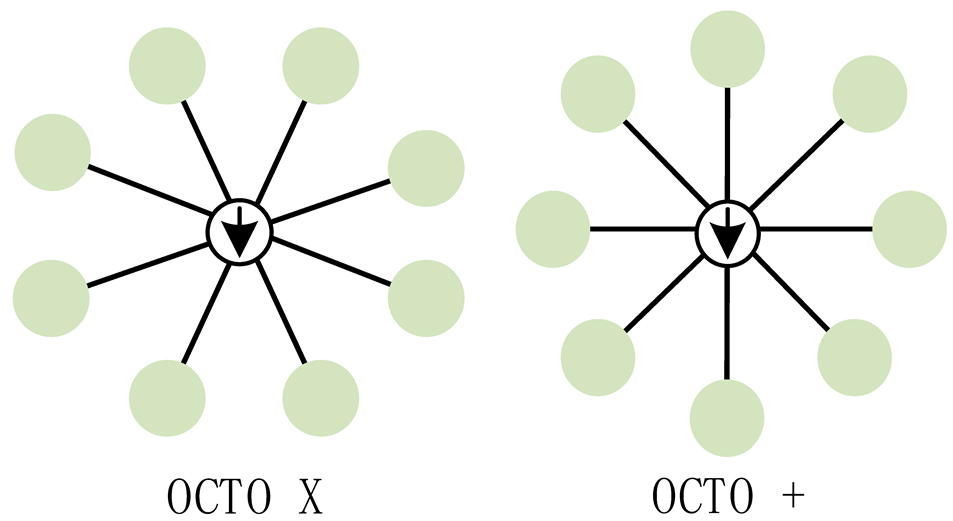
A multi-rotor drone is an aircraft system powered by three or more motor-driven propellers. It has the characteristics of vertical take-off and landing, high maneuverability, and the ability to hover in the air. Table 1 below classifies multi-rotor drones according to the number of rotors.

Table 1.
Multi-rotor drone classification.
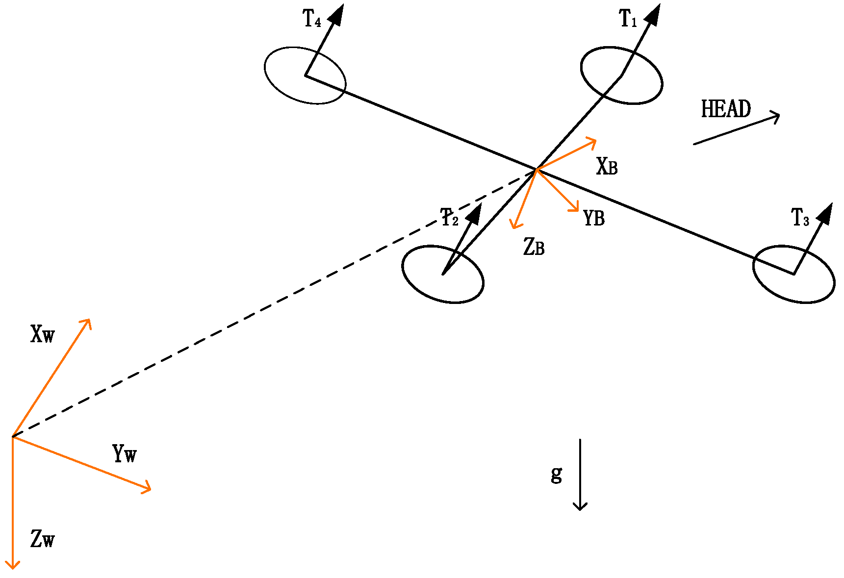
This paper will select the widely used QUAD X layout quadcopter to analyze the dynamic model. Usually, a basic quadcopter dynamic model is regarded as a particle with six degrees of freedom and a mass of . The dynamic analysis of this article is carried out, the Newton–Euler equation is established, and its dynamic formula is as follows:
where and represent the position and velocity of the drone mass in the world system, is a quaternion used to represent the rotation of the drone system relative to the world system, represents the diagonal matrix of the drone’s moment of inertia, is the gravitational acceleration, and is the drone’s mass.
In Formula (1), represents the total thrust obtained by the quadrotor drone, and represents the three-axis torque brought by the motor of the quadrotor drone. For the quadrotor drone, the calculation formula is as follows:
where represents the thrust brought by a single motor of the quadrotor drone, represents the total thrust obtained by the quadrotor drone, represents the three-axis torque of the quadcopter caused by the motor, and represents the position of each motor of the quadrotor drone in the machine system, as shown in Figure 1.

Figure 1.
Multi-rotor UAV dynamics model. Each circle in the diagram represents a rotor.
Formulas (1)–(3) constitute the basic quadcopter UAV dynamics model. Depending on the control level, simulation platforms will further perform simple modeling on the motor, introduce the variable of motor speed , build the motor mechanism into a first-order system, and model the relationship between motor thrust torque and speed. The most commonly used assumption is that the thrust and torque are proportional to the square of the motor speed, that is,
Among them, is the motor speed, represents the thrust of a single motor of a quadcopter drone, and represents the three-axis torque of the quadcopter caused by the motor.
The above model can cope well with low-speed or flight conditions close to suspension, but it ignores the resistance of the quadcopter during movement. In high-speed flight, the resistance it encounters cannot be ignored. To make the model more refined, the simulation platform takes the resistance of the drone into account and improves some formulas in Equation (1) by adding the effect of resistance on it:
where is the rotation matrix from the machine system to the world system, is the drone’s mass, is a quaternion, is the gravitational acceleration, represents the total thrust obtained by the quadcopter, is a diagonal matrix, and the elements , , and are the rotor drag coefficients of the three axes, which are proportional to the square of the flight speed of the quadrotor drone.
2.2. Preliminary Knowledge
Assume that there are N UAVs in the cluster system in d-dimensional space, and the relationship between UAVs is described by graph , where the set of vertices is and the set of edges is . The edge indicates that UAV i can receive information from UAV j, and the neighbor set of vertex i is . Without loss of generality, in this paper, we consider only undirected graphs, namely . We define the UAV formation , where the first UAVs are leaders and are followers. and are the sets of leaders and followers, respectively, and their respective positions are recorded as and .
For the UAV formation , the stress is the gravitational force on the edge , ; the structure of the stress matrix is determined from the basis diagram, the values of the matrix elements are determined from the formation queue, and the stress matrix is invariant for any affine transformation of the formation. Among them, the equilibrium stress satisfies , . The equilibrium stress matrix can be expressed as follows:
Among them, stress is the gravitational force on edge .
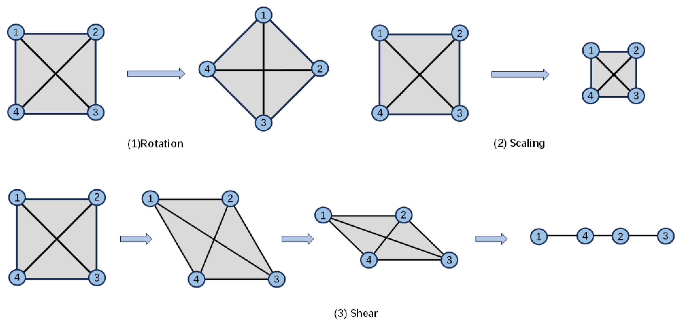
The affine transformation is implemented by linear transformation and translation composite, specifically translation, scaling, rotation, flipping, and miscutting, and the transformation preserves straight lines and planes, as shown in Equation (8):
where is the original coordinate of the multi-rotor UAV swarm in the two-dimensional plane, is the coordinate after affine transformation, is the affine transformation matrix, is the translation vector, and represent the scaling factor, and represent the shear multiplier, and and represent translations in two dimensions.
As shown in Figure 2, (1) is a rotation transformation, (2) is a scaling transformation, and (3) is a shear transformation. According to the mathematical properties of affine transformation, the UAV formation can achieve various functions, such as stable formation flight, formation rotation, scaling roundup, shear obstacle avoidance, etc.
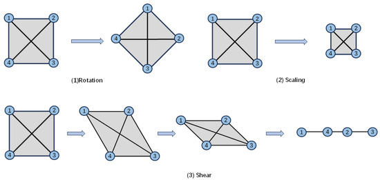
Figure 2.
Illustration of affine transformations of a nominal configuration. The numbers 1 to 4 in the picture are drones 1 to 4.
The stress matrix can be calculated after the formation is clear. During the flight of the multi-rotor UAV cluster, if there is no rotation, scaling, and shearing, the stress matrix will remain unchanged and does not need to be updated. When rotating, scaling, or shearing, the multi-rotor UAV cluster can obtain a new UAV formation through simple operations, such as arithmetic and trigonometric operations based on the existing stress matrix.
We define the target time-varying formation based on affine transformations as
where is the ideal position of the multi-rotor UAV swarm, the standard formation is a constant-value matrix, and are time-varying matrices, represents the Kronecker product, is an identity matrix, and is a vector whose elements are all equal to .
Single integrator modeling for multiple UAVs considering interference conditions is as follows:
Among them, is the position of the UAV, is the control input to be designed, is the interference term, , and .
The control goal of this paper is as follows: under the action of external disturbance , by constructing a distributed mode formation control law based on the stress matrix , the UAV cluster can form and maintain the desired affine transformation formation, control the current position of the UAV to approach the ideal position , and make the position error of the UAV cluster tend to 0, as shown in the formula
Among them, is the position of the drone, is the ideal position of the drone, and is the position error of the UAV.
To design the control law for multi-rotor UAV swarm formation, the following lemmas and assumptions are first given:
Lemma 1
(Rank condition for affine unfolding). A point set affine unfolds if and only if
and .
is the position matrix and is the position matrix augmented by 1 column:
Among them, is the position matrix, is the position matrix augmented by 1 column.
Lemma 2
([34] Rigidity Condition). Given an undirected graph and a standard formation , the formation is universally rigid and only if there exists a stress matrix such that is positive semidefinite and has rank .
Lemma 3
(Stress condition for affine capability). If in formation is affine expanded , at the same time, we have a semi-positive definite stress matrix and rank . When is non-singular, for any standard formation affine localizable, is uniquely determined by , . Where , the stress matrix is divided into blocks according to leaders and followers:
Among them, , .
Note 1.
Lemmas 1 and 2 are the prerequisites of Lemma 3. If Lemma 3 is satisfied, the position of the follower can be solved from the position of the leader, and the formation transformation of the entire formation can be achieved by performing an affine transformation on the leader formation.
Assumption 1.
Without loss of generality, assume that the number of multi-rotor UAV swarm leaders is , and there is a semi-positive definite stress matrix , and the rank of the stress matrix is .
3. Active UAV Obstacle Avoidance and Virtual UAV Design
In this section, the control strategy for the active obstacle avoidance function of the multi-rotor UAV swarm is proposed for the safety of the multi-rotor UAV swarm in an unknown environment. By the effect of the stress matrix, if the pilot UAV performs active obstacle avoidance when encountering an unknown obstacle, it will disrupt the multi-rotor UAV swarm’s formation, so only one pilot UAV is retained. The others are computed by the pilot UAV’s position to obtain the virtual UAVs in order to help the stability of the multi-rotor UAV swarm formation.
3.1. Stress Matrix-Based Active Obstacle Avoidance
An important aspect of multi-rotor UAV swarm mission completion is its ability to effectively navigate and maintain formation, especially in complex environments with obstacles. Therefore, the obstacle avoidance capability of a multi-rotor UAV swarm plays a vital role in achieving coordination and efficient mission execution.
In order to cope with more complex obstacle environments, based on the stress matrix-based multi-rotor UAV swarm formation, we added the functions of following UAVs to avoid obstacles and prevent collisions between UAVs. Through this improvement, each following UAV can not only fly in formation according to the established stress matrix but can also avoid obstacles by automatically adjusting its flight path when encountering unknown obstacles. In addition, the UAV can detect the relative distance to surrounding UAVs in real time and dynamically adjust it to prevent inter-aircraft collisions effectively.
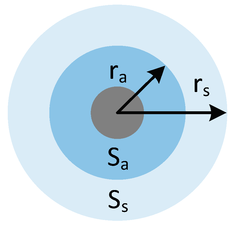
Through the drone’s own detection capabilities, it can actively detect nearby obstacles, thereby achieving the function of avoiding unknown obstacles. As shown in Figure 3, the communication range of each UAV is divided into a sensing area with a radius of and a warning area ; because the radius of the warning area, the warning area is within the sensing area , that is, .

Figure 3.
Schematic diagram of UAV active obstacle avoidance.
- (1)
- Obstacle avoidance behavior: During operation, the formation must avoid environmental obstacles. Let be the closest point on the boundary of obstacle within the sensing range of the UAV. When the UAV senses an obstacle, it will generate a thrust to maneuver around it. The thrust direction is as follows:
- (2)
- Collision avoidance behavior: In addition to obstacle avoidance, the control algorithm also needs to adjust the positions of the UAVs to avoid collisions between them. To solve this problem, we propose to use UAVs and that are not on the same wing but within each other’s sensing area; that is, if the UAV enters the warning area , then the UAV will exert a repulsive force to prevent the drone from entering the warning area . Let . The collision avoidance behavior is determined as follows:
In the work of this paper, the above reconfiguration idea is implemented through the following equation:
where is the positive reconfiguration gain, and are the positions of the UAV, is the smoothing factor, and is two UAVs and on the same wing; in the formula, enables the UAVs to adjust their positions to maintain the desired distance between UAVs. This behavior is also an anti-collision behavior for UAVs in the same wing.
In actual operation, the active obstacle avoidance function’s obstacle avoidance limit setting will affect the drone’s actual obstacle avoidance effect. If the value set is small, the active obstacle avoidance action of the drone will be delayed, causing the distance between the drone and the obstacle to be lower than the safe distance. Therefore, it is necessary to ensure that the distance range of the active obstacle avoidance of the drone is manageable. If the value set is large, the active obstacle avoidance function of the drone will be activated when it is unnecessary, affecting the formation of a multi-rotor drone cluster. Therefore, the distance of the active obstacle avoidance function of the drone needs to be set to an appropriate range.
As shown in Figure 4, the force is applied from one side, and the UAV responds by generating thrust to avoid potential collisions with obstacles, thus generating control signals. Accordingly, other following UAVs adjust their position based on the behavioral control signals. When the guiding UAV changes its position, the UAVs on the opposite wing re-align themselves through formation behavior. In this way, the entire UAV formation tends to move to the other side. In another case, when obstacles hit the formation from both sides, as shown in Figure 4, the drones on both sides of the multi-rotor drone cluster will move in the opposite direction of the obstacles. Other UAVs on the same wing can adjust their position accordingly by producing reconfiguration behavior. Thus, they can contract their wings in order to travel through complex obstacle environments.

Figure 4.
Schematic diagram of UAV obstacle avoidance. The red circle in the figure is the guide drone, the blue circle is the follower drone, and the gray rectangle is the obstacle. The arrow in the figure is the speed direction of the drone.
The position of the virtual drone can be calculated based on the position information of the pilot drone on the basis of the target formation. When the target formation of the multi-rotor drone cluster is rotated, scaled, and sheared, the multi-rotor drone cluster can obtain the position information of the virtual drone by performing simple operations, such as arithmetic operations and triangular matrix operations based on the existing target formation.
During the operation, specific errors in the sensor values may occur. Suppose the obtained value is larger than the actual value. In that case, the UAV’s active obstacle avoidance will be delayed, causing the distance between the UAV and the obstacle to be lower than the safe distance. Therefore, we must ensure that the distance range for the UAV’s active obstacle avoidance is manageable. Suppose the obtained value is smaller than the actual value. In that case, the UAV’s active obstacle avoidance function will be operated when it is not necessary, affecting the formation of the multi-rotor UAV cluster. Therefore, the distance setting for the UAV’s active obstacle avoidance function must be set to an appropriate range.
3.2. ‘Virtual UAV’ Design
The multi-rotor UAV swarm formation control task usually consists of two subtasks. The first is formation control, which directs the UAVs to form the desired geometry given the initial configuration. The second is formation maneuver control, which directs the UAVs to perform an overall maneuver so that the geometric parameters such as the center of mass, orientation, and scale of the UAV formation can be varied continuously.
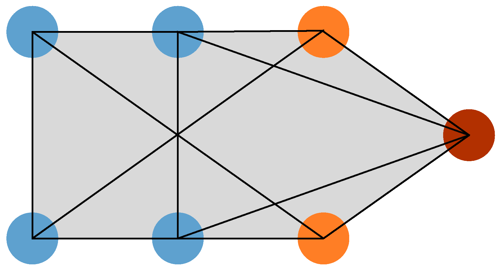
In the multi-rotor UAV swarm formation control system, the relative position and acceleration between UAVs can be effectively adjusted using a stress matrix-based approach to maintain the stability of the formation. However, when multiple UAVs act as navigators, the formation of the multi-rotor UAV swarm will be destroyed if the navigating UAV performs active obstacle avoidance when it encounters an unknown obstacle, and the concept of virtual UAVs is introduced, where only one real UAV is retained as the navigating UAV. The position and acceleration of each UAV are adjusted in real time by calculating the stress matrix. As shown in Figure 5, where the rightmost circle indicates the real UAV, the two circles to the left of the real UAV are the virtual UAVs, and the four circles to the left are the following UAVs. The control of the four following UAVs is implemented through the stress matrix based on the position information of the three UAVs on the right.
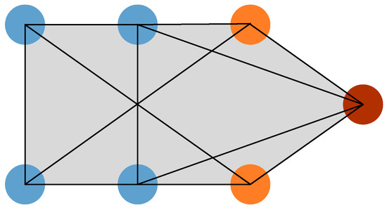
Figure 5.
Example diagram of multi-rotor UAV swarm formation. The red circle in the picture is the pilot drone, the orange circle is the virtual drone, and the blue circle is the follower drone.
The role of the virtual leader is crucial in the cooperative control and formation flight of multi-rotor UAV swarms. The main task of this virtual leader, which acts as an auxiliary computing node, is to accurately calculate its position and acceleration relative to that of the real leader UAV based on the dynamic information of the real leader’s position and acceleration. This method ensures the stability of the multi-rotor UAV swarm and the required rotation and formation transformation.
When a multi-rotor drone swarm is flying, only the pilot drone determines the flight route, and the virtual drone obtains the corresponding position information based on the target formation and the position information of the pilot drone. The follower drone calculates the corresponding acceleration based on the position information of the pilot drone and the virtual drone through the stress matrix and the corresponding rotation, compression, and shear information. During the calculation process, the virtual drone’s position information and the follower drone’s control amount can be obtained in real time through simple operations, such as four arithmetic operations and trigonometric functions. This ensures the feasibility of the experiment in this paper.
4. Formation Control Law Design
In UAV formation cooperative formation transformation control strategy, the design of formation control law is divided into two parts: the master–leader formation control law and the leader–slave formation control law.
4.1. Master–Leader Formation Control Laws
In this paper, the trajectory planning is performed by the host of the multi-rotor UAV swarm, and the formation transformation parameters are obtained from the transformed flight environment, so it is necessary to design the trajectory of the rest of the lead aircraft based on the host’s trajectory.
Lemma 4
([24,35]). For a group of UAVs modeled by , the formation control law based on the stress matrix is designed as
where is an element of the adjacency matrix concerning the leader formation , and is the position of the drone, and are ideal positions for drones, and the overall exponential stability of the target formation with a specified size is achieved.
The control law for the leader in the control law is shown in the following equation:
Among them, is an element of the adjacency matrix concerning the leader formation , and is the position of the drone, and are ideal positions for drones, and the overall exponential stability of the target formation with a specified size is achieved.
In the following, the leader control law is given according to Lemma 4, without proof.
Corollary 1.
Consider a set of UAVs modeled by . After online planning of the host trajectory is completed, the leader control law is designed as follows:
where is the leader adjacency matrix, is the time-varying leader position, is the time-varying target leader position, and is the affine transformation matrix. Then, the UAV formation can achieve the desired time-varying formation, such as .
Note 2.
Equation (20) is the matrix form of Equation (19), the difference being that Lemma 4 specifies the queue transformation parameters. At the same time, Corollary 1 replaces the constant-value matrix consisting of the affine transformation matrices derived from Equations (15) and (16) by replacing the deformation parameters specified in the control law of Lemma 4 by the transformation parameters based on the obstacle generation.
4.2. Leader–Slave Formation Control Laws
Consider three scenarios where the leader is stationary, the leader is moving at a constant speed, and the leader is moving at a variable speed, and control to overcome the effects of external disturbances on formation stability.
4.2.1. Leader Static
Consider first the case where the leader is stationary; for any , there is . In this case, the target formation is stationary.
Theorem 1.
Based on the model, considering the number of multi-rotor UAV swarm leaders and a semi-positive definite stress matrix , the rank of the stress matrix is , and the leader is stationary, the control law based on the stress matrix will be designed as follows:
where is a positive parameter, the UAV formation can achieve the desired time-varying formation, and is the position of the drone, and are ideal positions for drones, and is the interference term.
The matrix form of the control law (21) is expressed as:
Among them, is a positive parameter, the follower’s position , , , is the interference term, and is the tracking error.
Define the tracking error as
Among them, is the position of the drone and is the ideal position for drones.
Deriving the tracking error, it is obtained that
Among them, is a positive parameter, the follower’s position , , , is the interference term, and is the tracking error.
Construct the Lyapunov function as follows:
Among them, is the tracking error.
Derivation of Equation (25) yields:
Among them, is a positive parameter, the follower’s position , , , is the interference term, and is the tracking error. is a positive definite matrix, and is an upper bound on the interference, which can be made when . Therefore, it can be obtained that exists and is bounded. Equation (26) can be rewritten as follows:
Among them, is the tracking error, where is the smallest eigenvalue of the matrix , .
Integrating Equation (27) yields
Among them, is the tracking error, where is the smallest eigenvalue of the matrix , .
It follows from Barbalat’s Lemma that when , then the control law (21) allows the multi-rotor UAV swarm to keep the formation stable when the leader is stationary.
4.2.2. Leader Speed as a Constant Value
Considering that the leader is moving constantly, the control law (21) does not guarantee that the grid tracking error is zero. Therefore, a new control law needs to be designed as follows:
Theorem 2.
Based on the model, considering the number of multi-rotor UAV swarm leaders and a semi-positive definite stress matrix , the rank of the stress matrix is , and the leader moves at a uniform speed, the control law based on the stress matrix will be designed as follows:
Among them, and is the position of the drone, is the ideal position for drones, and is the interference term, where , , and are positive parameters, then the UAV formation can achieve the desired time-varying formation.
By introducing the variable to denote the integral term, the matrix form of Equation (29) can be expressed as follows:
Among them, the follower’s position ; ; ; is the tracking error; , , and are positive parameters; is the ideal position of the drone; and is the integral term.
Substituting Equation (30) for the tracking error yields
Among them, the follower’s position ; ; ; is the tracking error; , , and are positive parameters; is the integral term; and . The maximum value of the element in matrix is , is the target speed of the multi-rotor UAV swarm leader, and there is an upper limit to the speed of the UAVs, so is a known quantity.
Construct the Lyapunov function as follows:
Among them, is the tracking error.
Derivation of Equation (32) yields:
Among them, ; is the tracking error; , , and are positive parameters; and is the integral term. If , then is required, similar to the steps in the proof of Theorem 1, and it follows from Barbalat’s Lemma that when , . The control law (29) allows the multi-rotor UAV swarm to keep the formation stable while the leader moves at a uniform speed.
4.2.3. Time-Varying Leader Velocity
Considering the leader’s variable-speed motion, the control law (29) cannot guarantee zero tracking error. Therefore, a new control law has to be designed as follows:
Theorem 3.
Based on the model, considering the number of multi-rotor UAV swarm leaders and a semi-positive definite stress matrix , the rank of the stress matrix is , and the leader moves with variable speed, the control law based on the stress matrix will be designed as follows:
where is a positive parameter, is the position of the drone, is the ideal position of the drone, is the interference term, and . Since is a positive definite matrix and is constant, the desired time-varying formation of UAVs can be achieved.
Transformation of Equation (34) yields:
Among them, is a positive parameter, and are the positions of the drones, is the ideal position for drones, and is constant, and .
The matrix is of the form
Among them, is a positive parameter, the follower’s position , is the ideal position of the drone, , , is the tracking error, and is the interference term, which defines , , and is constant.
Simplifying Equation (36) yields
Among them, is a positive parameter, , , , is the tracking error, and is the interference term.
Substituting Equation (37) for the tracking error yields
Among them, is a positive parameter, , , is the tracking error, and is the interference term.
Construct the Lyapunov function as follows:
Among them, and is the tracking error.
Derivation of Equation (39) yields
Among them, is a positive parameter, is the interference term, , , and is the tracking error.
From Equation (40), when holds, that is, when , there is . Similar to the proof step of Theorem 1, from Barbalat’s Lemma, when , . At this point, the control law (34) allows the multi-rotor UAV swarm to maintain formation stability as the leader makes variable-speed movements.
Note 3.
Theorems 1–3 are the control laws of slave formation in three cases: namely, when the leader is stationary, when the leader is moving at a constant speed, and when the leader is moving at a variable speed, considering the external interference conditions. In practical applications, the leader is stationary or moving at a constant speed, which is rare, and more consideration should be given to the case of the leader moving at a variable speed. From the derivation, we know that the control law (34) only requires that the UAV formation can maintain stable flight as long as the design k is larger than the maximum value of external disturbance.
5. Simulation Verification
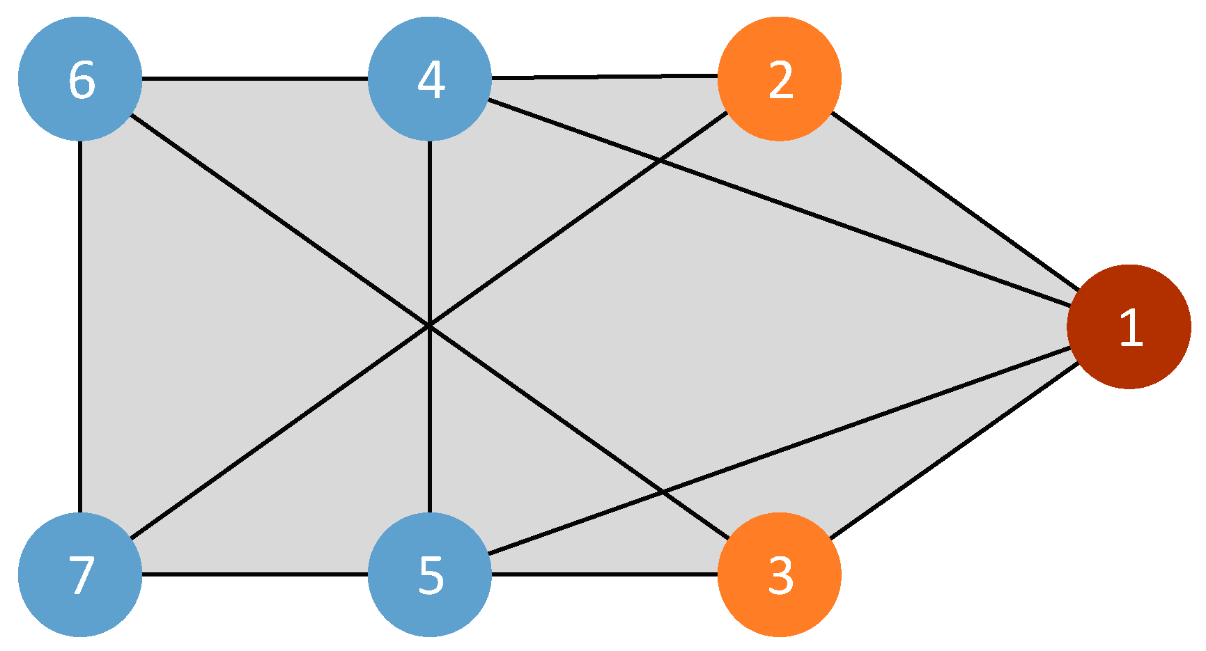
In order to verify the control law of formation transformation in a complex environment, a simulation experiment is designed under the rank condition and rigidity condition of affine expansion. Assume that No. 1 is the pilot drone, No. 2–3 are auxiliary drones of “auxiliary computing nodes”, and No. 4–7 are follower drones, among which No. 1 leader is the host. The communication topology of the drone cluster system is shown in Figure 6.
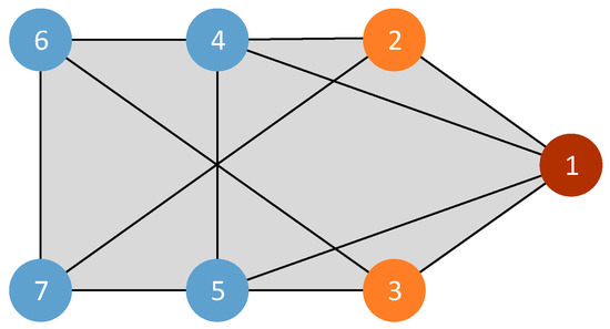
Figure 6.
Example diagram of multi-rotor UAV swarm formation. The red circle in the picture is the pilot drone, the orange circle is the virtual drone, and the blue circle is the follower drone. The numbers in the picture are the drone numbers.
Under this communication topology, the stress matrix is calculated using the algorithm in the literature as follows:
During the simulation, the motion trajectory of the host was generated offline, and the flight paths of the remaining leading aircraft were generated according to the actual flight environment. In addition, in order to maintain the stability of the UAV cluster formation flight, the leading aircraft cluster must not only meet the number required by Lemma 1 but also maintain the full connectivity of the leading aircraft cluster communication topology, which can ensure that after the host is damaged, the remaining leading aircraft can replace the host position to navigate and generate the flight paths of the remaining leading aircraft, thereby improving the robustness of the UAV cluster.
In the simulation experiment, the communication range between the quadrotor drone clusters was set to one hundred meters to ensure communication between them; the detection range of the quadrotor drone for obstacles was set to two meters; and the drone flight speed was set to a maximum of five meters per second.
5.1. Multi-Rotor UAV Formation Verification Experiment in Obstacle-Free Environment
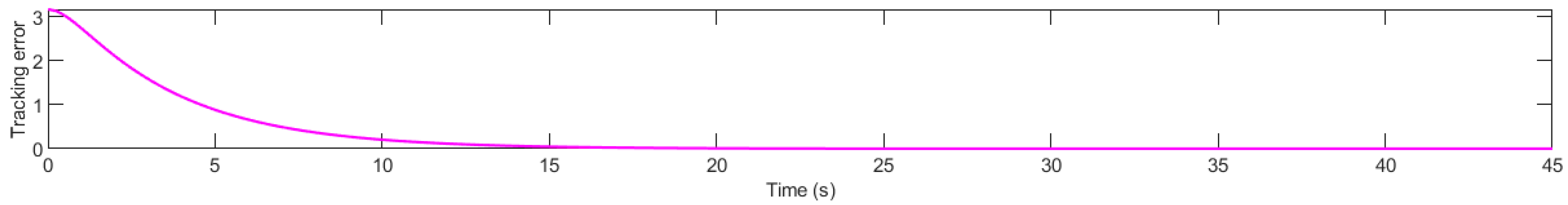
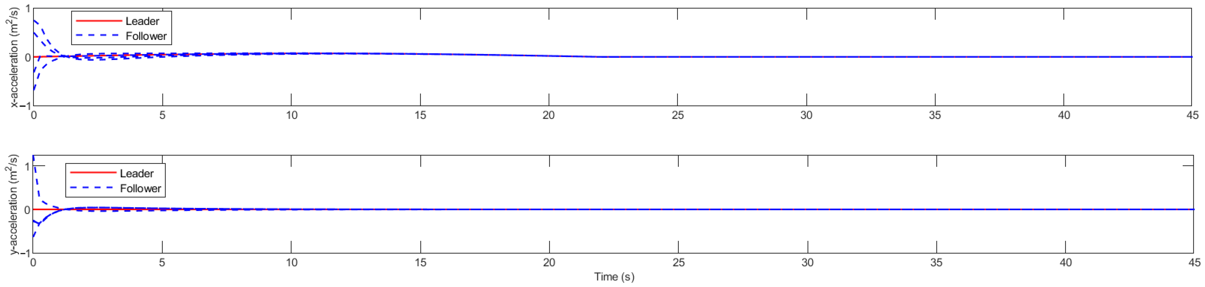
As shown in Figure 7, the simulation experiment shows that the multi-rotor drone swarm takes off from an irregular initial formation and then quickly forms a target formation through the calculation of the stress matrix. The position tracking error is shown in Figure 8. When the multi-rotor drone swarm is flying in formation, the tracking error converges to close to zero at around the 13th second, indicating that the multi-rotor drone swarm has formed a standard formation. Figure 9 is a schematic diagram of the acceleration change. The following drone changes its position by adjusting the acceleration in real time to achieve the target formation. The initial formation of the multi-rotor drone cluster is not the target formation, so the acceleration of the follower drone is not completely consistent with that of the lead drone. The target formation is finally formed through acceleration control. The simulation experiment shows that the multi-rotor drone swarm can form a target formation and maintain the formation in a relatively short time.
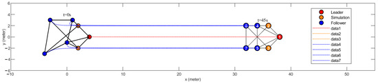
Figure 7.
Schematic diagram of formation trajectory simulation. The numbers in the picture are the numbers of the drones.
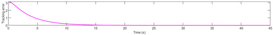
Figure 8.
Position tracking error.
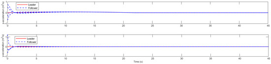
Figure 9.
Acceleration change.
5.2. Multi-Rotor UAV Swarm Obstacle Avoidance Verification Experiment in a Unilateral Obstacle Environment
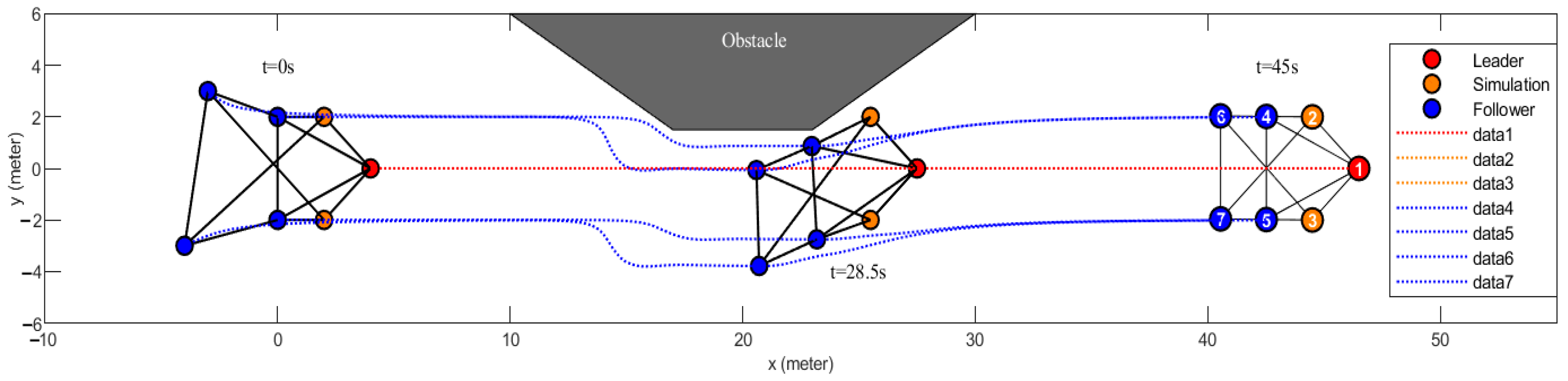
As shown in Figure 10, the multi-rotor UAV swarm can be seen in the simulation experiment to take off from an irregular initial formation and then quickly integrate into a target formation. When an obstacle exists on one side of the multi-rotor UAV swarm during flight, the multi-rotor UAV swarm moves in the direction of no obstacle to pass through the unknown obstacle environment smoothly. Simulation experiments show that the multi-rotor UAV swarm can maintain formation and actively avoid obstacles in an unknown environment.
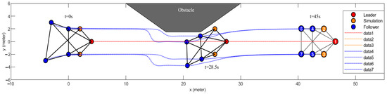
Figure 10.
Schematic diagram of formation obstacle avoidance trajectory simulation. The numbers in the picture are the numbers of the drones.
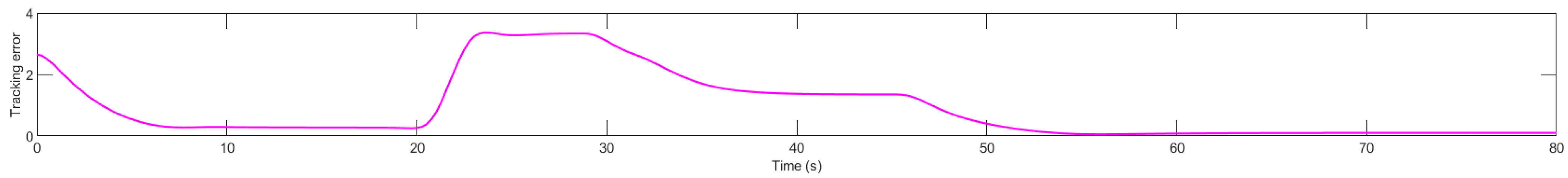
The position tracking error is shown in Figure 11. When the multi-rotor UAV swarm formation is in flight, the tracking error converges to near zero at about the eighth second as the multi-rotor UAV swarm assembles into a standard formation. The position tracking error becomes more significant as the unknown obstacle is found to follow the UAV to perform active obstacle avoidance at about the 20th second. Then, it passes through the unknown obstacle and resumes the formation at about the 55th second. When a multi-rotor UAV cluster encounters an obstacle during flight, the UAV actively avoids the obstacle, causing the formation of the UAV cluster to change and the position error to increase accordingly. After passing the obstacle, the UAV cluster returns to the target formation under the formation effect of the stress matrix. Figure 12 shows the schematic diagram of the change in acceleration. The speed and acceleration are consistent with the leader when the formation is flying stably. When encountering obstacles, the drone actively avoids them by adjusting its acceleration, so the acceleration of the multi-rotor drone cluster is not exactly the same during the compilation process.
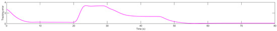
Figure 11.
Position tracking error.
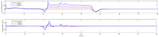
Figure 12.
Acceleration change.
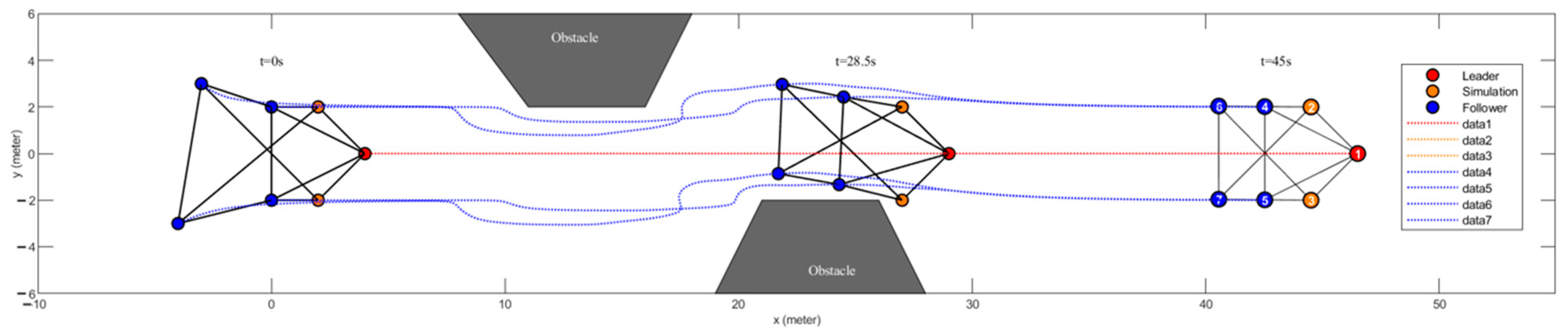
As shown in Figure 13, the simulation experiment shows that the multi-rotor drone group takes off from the irregular initial formation and quickly merges into the target formation. When there is an obstacle on one side of the multi-rotor drone group during flight, the multi-rotor drone group moves in the direction of no obstacles to pass through the unknown environment smoothly. When reencountering an obstacle, the multi-rotor drone group moves in the direction of no obstacles again to ensure smooth passage through the unknown obstacle environment; the simulation experiment shows that the multi-rotor drone group can maintain formation in an unknown environment and actively avoid unknown obstacles.
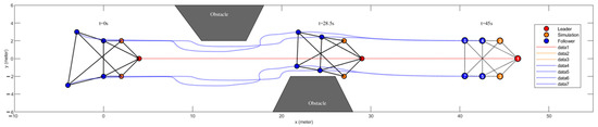
Figure 13.
Schematic diagram of formation obstacle avoidance trajectory simulation. The numbers in the picture are the numbers of the drones.
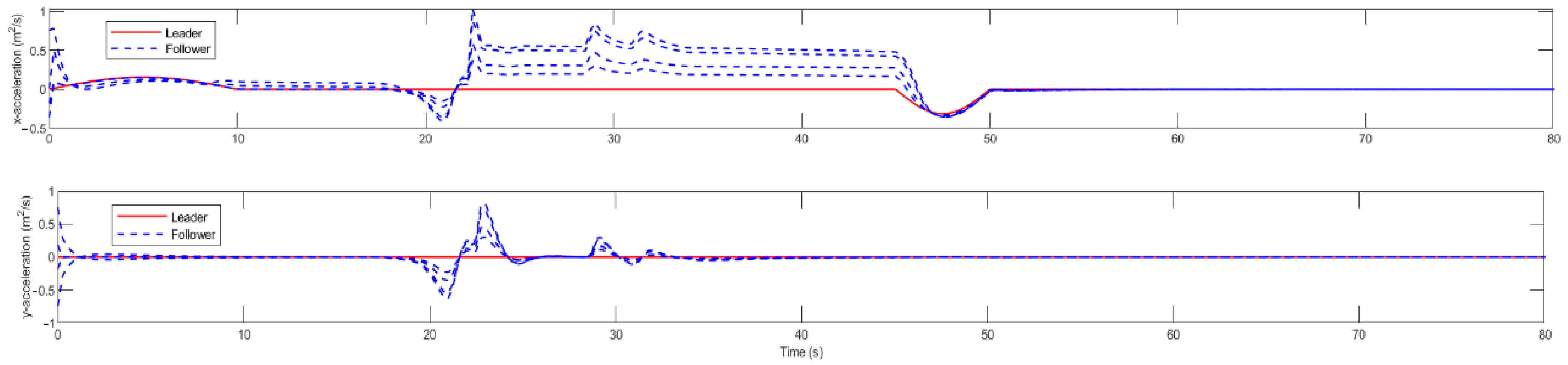
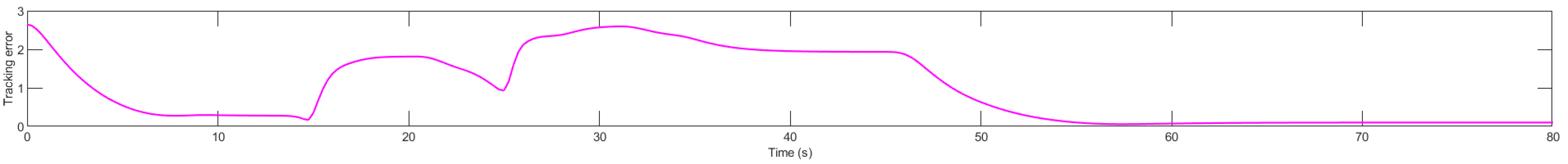
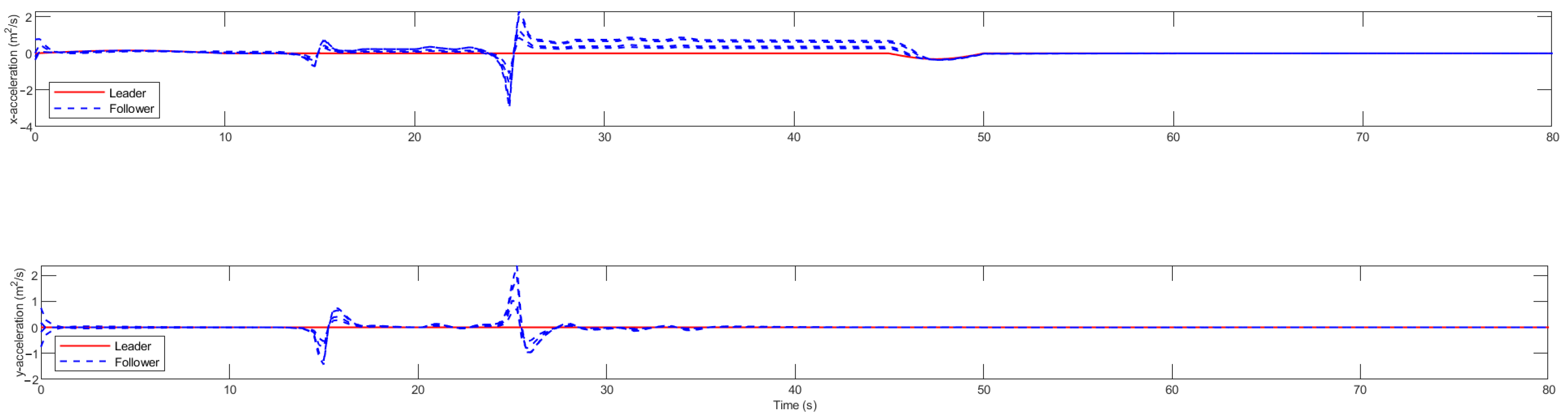
The position tracking error is shown in Figure 14. When the multi-rotor drone group flies in formation, as the multi-rotor drone group forms a standard formation, the tracking error finds an unknown obstacle at about 15 s. It follows the drone to avoid obstacles actively. The position tracking error increases, encounters the second obstacle at about 25 s, avoids the obstacle, and finally restores the formation. When a multi-rotor UAV cluster encounters an obstacle during flight, the UAV actively avoids the obstacle, causing the formation of the UAV cluster to change and the position error to increase accordingly. After passing the obstacle, the UAV cluster returns to the target formation under the formation effect of the stress matrix. Figure 15 is a schematic diagram of acceleration change. The speed and acceleration are the same as those of long aircraft during a stable flight of the formation. When encountering obstacles, the drone actively avoids them by adjusting its acceleration, so the acceleration of the multi-rotor drone cluster is not exactly the same during the compilation process.
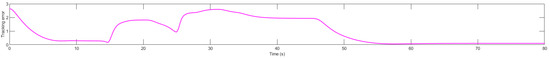
Figure 14.
Position tracking error.
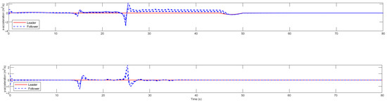
Figure 15.
Acceleration change.
5.3. Multi-Rotor UAV Swarm Obstacle Avoidance Verification Experiment in a Bilateral Obstacle Environment
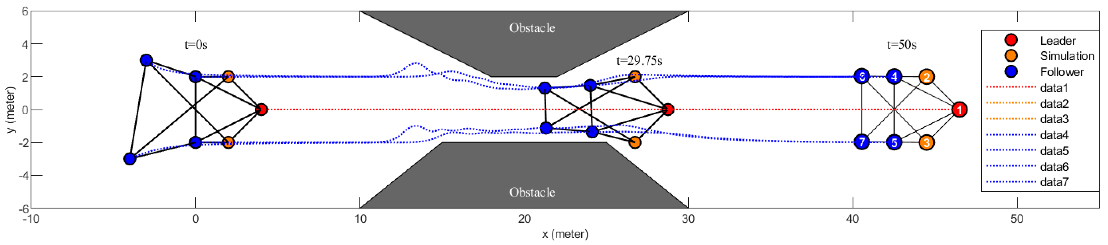
As shown in Figure 16, the multi-rotor UAV swarm can be seen in the simulation experiment to take off from an irregular initial formation and then quickly integrate into a target formation. When the multi-rotor UAV swarm has obstacles on one side during flight, the multi-rotor UAV swarm as a whole moves in the direction of no obstacles in order to pass through the unknown obstacle environment smoothly, and when both sides are in obstacles during flight, the UAVs move in the opposite direction of the obstacles on both sides in order to pass through the unknown obstacle environment smoothly, and the simulation experiments show that the multi-rotor UAV swarm can maintain the formation in the unknown environment and actively avoid the unknown obstacles.

Figure 16.
Schematic diagram of formation obstacle avoidance trajectory simulation. The numbers in the picture are the numbers of the drones.
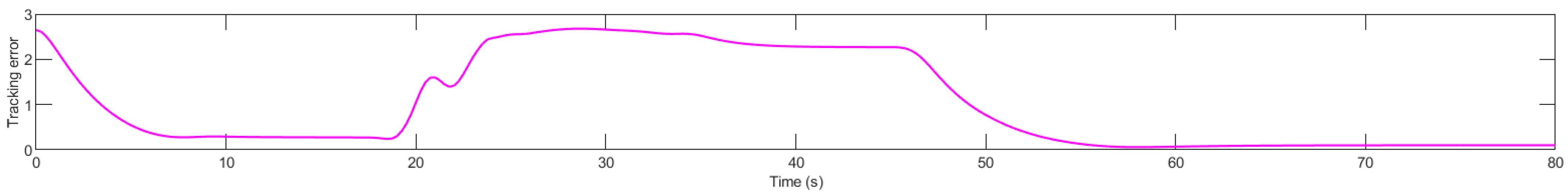
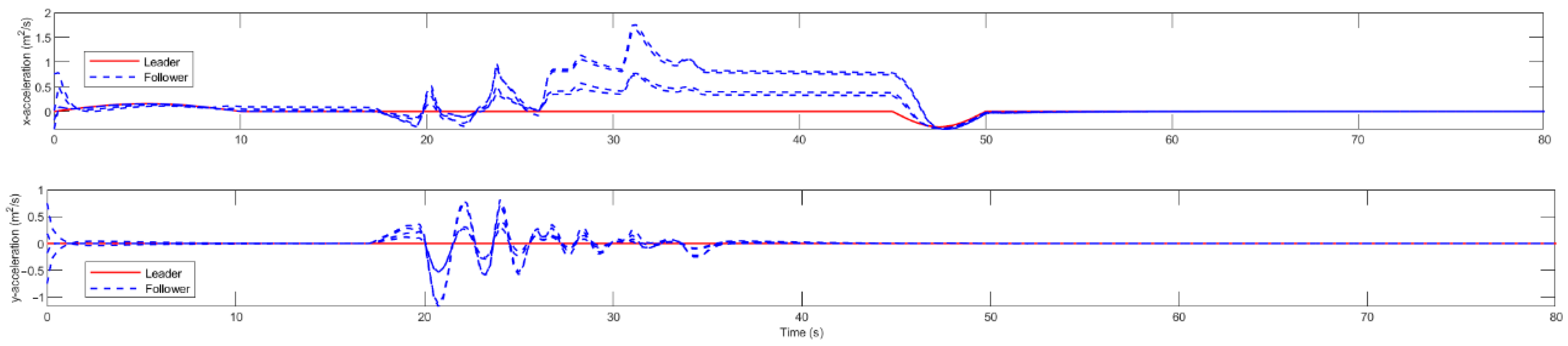
The positional tracking error is shown in Figure 17. When the multi-rotor UAV swarm is flying in formation, the tracking error converges to near zero at about the eighth second as the multi-rotor UAV swarm assembles into a standard formation, and then at about the 19th second as the unknown obstacle is found and follows the UAV for active obstacle avoidance, the positional tracking error becomes more extensive, and then passes through the unknown obstacle and recovers the formation at about the 55th second. When a multi-rotor UAV cluster encounters an obstacle during flight, the UAV actively avoids the obstacle, causing the formation of the UAV cluster to change and the position error to increase accordingly. After passing the obstacle, the UAV cluster returns to the target formation under the formation effect of the stress matrix. Figure 18 shows the schematic diagram of the change in acceleration; the speed and acceleration are the same as that of the leader aircraft when the formation is flying stably. When encountering obstacles, the drone actively avoids them by adjusting its acceleration, so the acceleration of the multi-rotor drone cluster is not exactly the same during the compilation process.
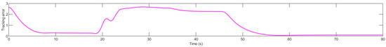
Figure 17.
Position tracking error.
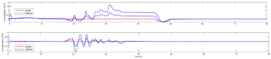
Figure 18.
Acceleration change.
5.4. UAV Formation Verification Experiment Using Virtual UAVs
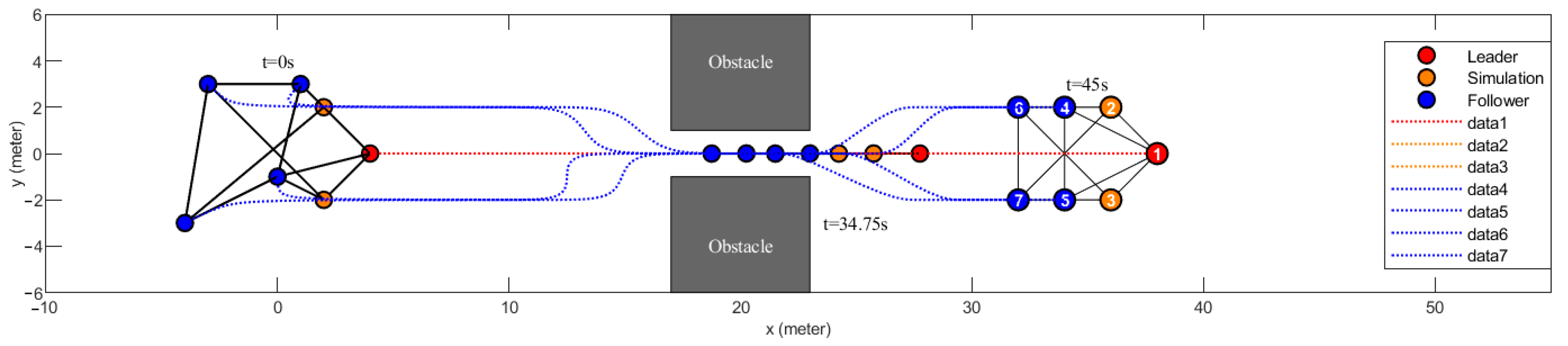
As shown in Figure 19, in the simulation experiment, the multi-rotor UAV swarm takes off in an irregular pattern, and the experimental results show that the multi-rotor UAV swarm transforms into a ‘one’ formation when it passes through the narrow obstacle channel. The shear transformation occurs in two dimensions at this time; when the standard formation is symmetric, the unidirectional shear transformation will cause a symmetric UAV collision. When the standard formation is symmetric, the one-way shear transformation will cause symmetric UAVs to collide. In the actual flight process, it is difficult for the multi-rotor UAV swarm to pass the obstacle vertically; the angle difference between the trajectory and the obstacle will make the multi-rotor UAV swarm shear transformation into two dimensions to avoid collision and damage to the UAV in the swarm.
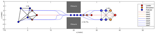
Figure 19.
Schematic diagram of formation obstacle avoidance trajectory simulation. The numbers in the picture are the numbers of the drones.
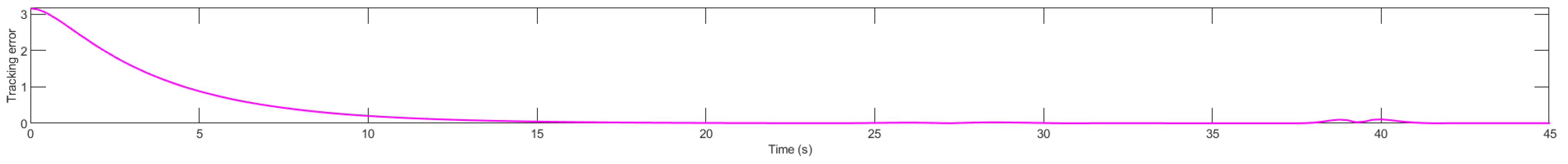
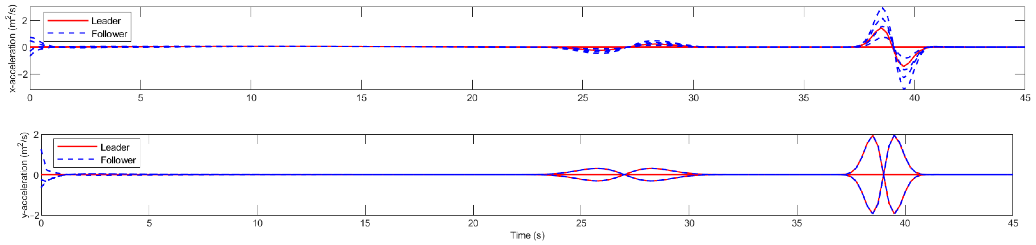
Figure 20 shows the position tracking error. When the multi-rotor UAV swarm is flying in formation, the tracking error converges to near zero at about the 15th second as the multi-rotor UAV swarm assembles into a standard formation. When a swarm of multi-rotor UAVs passes through a known obstacle, the target formation is transformed through the shearing of the stress matrix, so the actual formation is consistent with the ideal formation, and the position error is extremely small. Figure 21 shows the change in acceleration, and the speed and acceleration are the same as the leader when the formation is in stable flight. When encountering obstacles, the drone actively avoids them by adjusting its acceleration, so the acceleration of the multi-rotor drone cluster is not exactly the same during the compilation process.
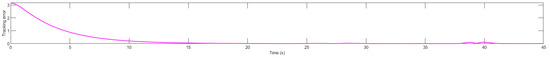
Figure 20.
Position tracking error.
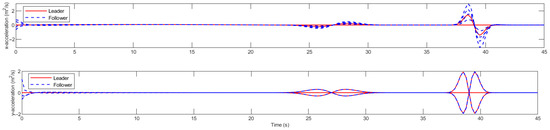
Figure 21.
Acceleration change.
The simulation results show that under the control law designed in this paper, during the maneuvering flight of the UAV cluster, its centroid and geometric pattern can change according to obstacles, and it can complete stable formation flight under obstacle environment and interference conditions.
5.5. Drone Swarm Formation Obstacle Avoidance Simulation Experiment
RflySim is an ecosystem released by the Reliable Flight Control Group of Beihang. The version of RflySim3D used in the experiments in this article is 4.27.2.0. It adopts the Model-Based Design (MBD) idea, which can be used for the control and safety testing of unmanned systems. Since MATLAB/Simulink supports the whole design phase of MBD, we chose them as the core programming platform for control/vision/cluster algorithm development, which can simulate unmanned intelligence clusters. Comparisons between physical and simulation experiments of multi-wing flights based on the RFlySim platform have verified the high accuracy level of the platform’s simulations. The platform has been subjected to quantitative analysis tests and comparative fault injection experiments. The confidence level of the platform is more than 90% (with the lowest confidence interval accuracy; this fully confirms the high reliability and usefulness of the platform—the core value body of the platform is 60%) now in the software and hardware-in-the-loop simulation, which includes the unique CopterSim, the vision system plug-in, and the development model. The software platform components are shown in Figure 22.
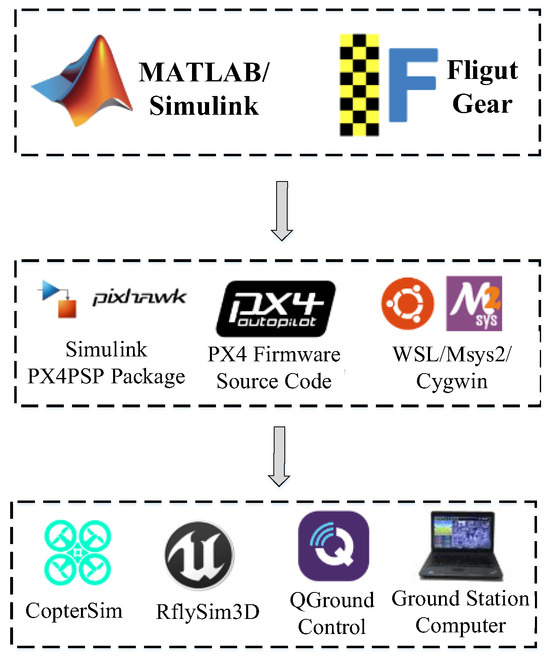
Figure 22.
Composition diagram of the RflySim software platform.
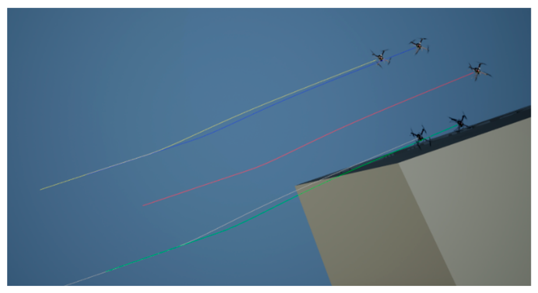
As shown in Figure 23, the quadrotor UAV swarm consists of five UAVs, each of which uses different colored lines to record the trajectory, where the middle UAV, i.e., the one with the red line recording the trajectory, is the natural leader. It is evident in the simulation that during the flight, when there is an obstacle on the right side of the quadrotor UAV swarm, the UAVs make a deviation to the left side and successfully avoid the obstacle, and that all of the following UAVs moved to the other side of the obstacle.
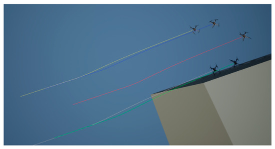
Figure 23.
RflySim simulation diagram.
This paper uses the stress matrix to perform the formation task of a multi-rotor drone cluster. It verifies the reliability of this method through a particular scale of drone cluster formation. Suppose a larger-scale multi-rotor drone cluster is used. In that case, ensuring that the target formation meets the relevant requirements of the stress matrix in the previous article is necessary. If the flight effect of the subsequent drones does not reach the ideal state, the number of virtual drones can be appropriately increased, or the position of the virtual drones can be adjusted.
In the simulation of RflySim, we can see that the quadcopter swarm successfully avoided obstacles. The position transmission of the quadcopter swarm may be delayed during the actual flight, and then there is a slight error between the control information calculated by the stress matrix and the actual control information, which leads to a specific position error between the position of the quadcopter and the ideal position. Similarly, suppose the position information of the pilot drone is incorrect due to the delay. In that case, the calculated position information of the virtual drone will have an error accordingly. Then, there will be an error between the control information of the follower drone and the actual control information, resulting in a specific error between the position of the quadcopter and the ideal position. Therefore, the quadcopter swarm needs to ensure specific communication and timely information feedback during the flight.
6. Conclusions
This paper adopts a formation method for multi-rotor UAV clusters based on a stress matrix and proves the stability of the formation through simulation experiments. Multi-rotor UAV clusters can pass through known obstacle environments by rotating, scaling, and shearing the target formation but cannot pass through unknown obstacle environments. This paper designs an active obstacle avoidance function for multi-rotor UAV cluster formation based on a stress matrix. Considering that when a multi-rotor UAV cluster flies in formation, if the pilot UAV performs active obstacle avoidance, the target formation of the multi-rotor UAV cluster will be destroyed. This paper proposes a virtual UAV as an “auxiliary computing node” to complete the formation task of the multi-rotor UAV cluster and realizes the safe passage of the multi-rotor UAV cluster through an unknown environment in the presence of unknown obstacles. The simulation results show that the multi-rotor UAV cluster can safely pass through known obstacle environments and unknown obstacle environments. The simulation experiment in this paper is a two-dimensional space simulation experiment, which verifies the feasibility of the multi-rotor UAV cluster to form and avoid obstacles at the same height. For more complex formations of multi-rotor UAV clusters in three-dimensional space and when facing more complex three-dimensional obstacles, the formation effect and obstacle avoidance effect of the multi-rotor UAV cluster need further verification. Future research directions may consider the formation problem of three-dimensional target formations of multi-rotor UAV clusters in three-dimensional space and the corresponding obstacle avoidance problem.
Author Contributions
Conceptualization, methodology, validation, writing, Z.Q.; conceptualization, data curation, formal analysis, Z.Q., L.Z., Y.C. and Z.L.; supervision, funding acquisition, and review, Z.Q., L.Z., Y.C. and Z.L. All authors have read and agreed to the published version of the manuscript.
Funding
This research received no external funding.
Data Availability Statement
No new data were created or analyzed in this study. Data sharing is not applicable to this article.
Conflicts of Interest
The authors declare no conflicts of interest.
References
- Fahlstrom, P.G.; Gleason, T.J.; Sadraey, M.H. Introduction to UAV Systems; John Wiley & Sons: Hoboken, NJ, USA, 2022. [Google Scholar]
- Fan, B.; Li, Y.; Zhang, R.; Fu, Q. Review on the technological development and application of UAV systems. Chin. J. Electron. 2020, 29, 199–207. [Google Scholar] [CrossRef]
- Pan, Z.; Zhang, C.; Xia, Y.; Xiong, H.; Shao, X. An improved artificial potential field method for path planning and formation control of the multi-UAV systems. IEEE Trans. Circuits Syst. II Express Briefs 2021, 69, 1129–1133. [Google Scholar] [CrossRef]
- Fu, X.; Pan, J.; Wang, H.; Gao, X. A formation maintenance and reconstruction method of UAV swarm based on distributed control. Aerosp. Sci. Technol. 2020, 104, 105981. [Google Scholar] [CrossRef]
- Ali, Z.A.; Israr, A.; Alkhammash, E.H.; Hadjouni, M. A Leader-Follower Formation Control of Multi-UAVs via an Adaptive Hybrid Controller. Complexity 2021, 2021, 9231636. [Google Scholar] [CrossRef]
- Zhang, D.; Duan, H.; Zeng, Z. Leader–follower interactive potential for target enclosing of perception-limited UAV groups. IEEE Syst. J. 2021, 16, 856–867. [Google Scholar] [CrossRef]
- Jiang, C.; Fang, Y.; Zhao, P.; Panneerselvam, J. Intelligent UAV identity authentication and safety supervision based on behavior modeling and prediction. IEEE Trans. Ind. Inform. 2020, 16, 6652–6662. [Google Scholar] [CrossRef]
- Fina, L.; Smith, D.S.; Carnahan, J.; Sevil, H.E. Entropy-based distributed behavior modeling for multi-agent UAVs. Drones 2022, 6, 164. [Google Scholar] [CrossRef]
- Li, L.; Sheng, W.; Hu, C. Research on formation keeping of multi-rotor UAVs based on improved virtual structure method. J. Phys. Conf. Ser. 2020, 1631, 012106. [Google Scholar] [CrossRef]
- Wu, E.; Sun, Y.; Huang, J.; Zhang, C.; Li, Z. Multi UAV cluster control method based on virtual core in improved artificial potential field. IEEE Access 2020, 8, 131647–131661. [Google Scholar] [CrossRef]
- Jiang, Z.; Ge, J.; Xu, Q.; Yang, T. Terminal Distributed Cooperative Guidance Law for Multiple UAVs Based on Consistency Theory. Appl. Sci. 2021, 11, 8326. [Google Scholar] [CrossRef]
- Tao, C.; Zhang, R.; Song, Z.; Wang, B.; Jin, Y. Multi-UAV Formation Control in Complex Conditions Based on Improved Consistency Algorithm. Drones 2023, 7, 185. [Google Scholar] [CrossRef]
- Zhang, J.; Yan, J.; Zhang, P. Multi-UAV formation control based on a novel back-stepping approach. IEEE Trans. Veh. Technol. 2020, 69, 2437–2448. [Google Scholar] [CrossRef]
- Justh, E.W.; Krishnaprasad, P.S. A Simple Control Law for UAV Formation Flying; Technical Report 2002-38; Institute for Systems Research: College Park, MD, USA, 2002. [Google Scholar]
- Ouyang, Q.; Wu, Z.; Cong, Y.; Wang, Z. Formation control of unmanned aerial vehicle swarms: A comprehensive review. Asian J. Control 2023, 25, 570–593. [Google Scholar] [CrossRef]
- Hu, Z.; Xu, X. Formation control for an UAV team with environment-aware dynamic constraints. IEEE Trans. Intell. Veh. 2023, 25, 570–593. [Google Scholar] [CrossRef]
- Azam, M.A.; Mittelmann, H.D.; Ragi, S. UAV formation shape control via decentralized markov decision processes. Algorithms 2021, 14, 91. [Google Scholar] [CrossRef]
- Zhang, J.-D.; Shi, Z.-Y.; Zhang, A.-L.; Yang, Q.-M.; Shi, G.-Q.; Wu, Y. UAV trajectory prediction based on flight state recognition. IEEE Trans. Aerosp. Electron. Syst. 2023, 60, 2629–2641. [Google Scholar] [CrossRef]
- Chung, W.; Son, H. Fault-tolerant control of multirotor UAVs by control variable elimination. IEEE/ASME Trans. Mechatron. 2020, 25, 2513–2522. [Google Scholar] [CrossRef]
- Ye, R.; Liu, P.; Shi, K.; Yan, B. State damping control: A novel simple method of rotor UAV with high performance. IEEE Access 2020, 8, 214346–214357. [Google Scholar] [CrossRef]
- Lin, Z.; Wang, L.; Chen, Z.; Fu, M.; Han, Z. Necessary and sufficient graphical conditions for affine formation control. IEEE Trans. Autom. Control 2015, 61, 2877–2891. [Google Scholar] [CrossRef]
- Zhao, S. Affine formation maneuver control of multiagent systems. IEEE Trans. Autom. Control 2018, 63, 4140–4155. [Google Scholar] [CrossRef]
- Xu, Y.; Zhao, S.; Luo, D.; You, Y. Affine formation maneuver control of high-order multi-agent systems over directed networks. Automatica 2020, 118, 109004. [Google Scholar] [CrossRef]
- Yang, Q.; Sun, Z.; Cao, M.; Fang, H.; Chen, J. Stress-matrix-based formation scaling control. Automatica 2019, 101, 120–127. [Google Scholar] [CrossRef]
- Asadi, D.; Bagherzadeh, S.A. Nonlinear adaptive sliding mode tracking control of an airplane with wing damage. Proc. Inst. Mech. Eng. Part G J. Aerosp. Eng. 2018, 232, 1405–1420. [Google Scholar] [CrossRef]
- Peng, P.; Dong, W.; Chen, G.; Zhu, X. Obstacle avoidance of resilient UAV swarm formation with active sensing system in the dense environment. In Proceedings of the 2022 IEEE/RSJ International Conference on Intelligent Robots and Systems (IROS), Kyoto, Japan, 23–27 October 2022; IEEE: New York City, NY, USA, 2022; pp. 10529–10535. [Google Scholar]
- Wu, J.; Wang, H.; Liu, Y.; Zhang, M.; Wu, T. Learning-based fixed-wing UAV reactive maneuver control for obstacle avoidance. Aerosp. Sci. Technol. 2022, 126, 107623. [Google Scholar] [CrossRef]
- Chen, Y.; Huang, S.; Fitch, R. Active SLAM for mobile robots with area coverage and obstacle avoidance. IEEE/ASME Trans. Mechatron. 2020, 25, 1182–1192. [Google Scholar] [CrossRef]
- Roghair, J.; Niaraki, A.; Ko, K.; Jannesari, A. A vision-based deep reinforcement learning algorithm for UAV obstacle avoidance. In Proceedings of the Intelligent Systems Applications: Proceedings of the 2021 Intelligent Systems Conference (IntelliSys), Virtual, 2–3 September 2021; Springer International Publishing: Cham, Switzerland, 2022; Volume 1. [Google Scholar]
- Bashir, N.; Boudjit, S.; Dauphin, G.; Zeadally, S. An obstacle avoidance approach for UAV path planning. Simul. Model. Pract. Theory 2023, 129, 102815. [Google Scholar] [CrossRef]
- Tai, J.J.; Phang, S.K.; Wong, Y.M.F. Optimized autonomous UAV design with obstacle avoidance capability. In Proceedings of the AIP Conference Proceedings 2020, Ekaterinburg, Russia, 18–22 May 2020; AIP Publishing: Melville, NY, USA; Volume 2233. [Google Scholar]
- Yasin, J.N.; Mohamed, S.A.S.; Haghbayan, M.-H.; Heikkonen, J.; Tenhunen, H.; Plosila, J. Unmanned aerial vehicles (UAVs): Collision avoidance systems and approaches. IEEE Access 2020, 8, 105139–105155. [Google Scholar] [CrossRef]
- Bui, D.N.; Phung, M.D.; Duy, H.P. Self-Reconfigurable V-shape Formation of Multiple UAVs in Narrow Space Environments. In Proceedings of the 2024 IEEE/SICE International Symposium on System Integration (SII), Ha Long, Vietnam, 8–11 January 2024; IEEE: New York City, NY, USA, 2024. [Google Scholar]
- Do, H.; Nguyen, H.; Nguyen, C.; Nguyen, M.; Nguyen, M. Formation control of multiple unmanned vehicles based on graph theory: A Comprehensive Review. EAI Endorsed Trans. Mob. Commun. Appl. 2022, 7, e3. [Google Scholar] [CrossRef]
- Xu, Y.; Zheng, W.; Luo, D.; Duan, H. Dynamic affine formation control of networked under-actuated quad-rotor UAVs with three-dimensional patterns. J. Syst. Eng. Electron. 2022, 33, 1269–1285. [Google Scholar]


Disclaimer/Publisher’s Note: The statements, opinions and data contained in all publications are solely those of the individual author(s) and contributor(s) and not of MDPI and/or the editor(s). MDPI and/or the editor(s) disclaim responsibility for any injury to people or property resulting from any ideas, methods, instructions or products referred to in the content. |
© 2024 by the authors. Licensee MDPI, Basel, Switzerland. This article is an open access article distributed under the terms and conditions of the Creative Commons Attribution (CC BY) license (https://creativecommons.org/licenses/by/4.0/).