Article

A Parallel-GPU DGTD Algorithm with a Third-Order LTS Scheme for Solving Multi-Scale Electromagnetic Problems

by
Marlon J. Lizarazo
1,* and
Elson J. Silva
2
1
Graduate Program in Electrical Engineering, Universidade Federal de Minas Gerais, Av. Antônio Carlos 6627, Belo Horizonte 31270-901, MG, Brazil
2
Department of Electrical Engineering, Universidade Federal de Minas Gerais, Belo Horizonte 31270-901, MG, Brazil
*
Author to whom correspondence should be addressed.
Mathematics 2024, 12(23), 3663; https://doi.org/10.3390/math12233663
Submission received: 20 September 2024 / Revised: 4 November 2024 / Accepted: 8 November 2024 / Published: 22 November 2024
(This article belongs to the Special Issue Advances in Computational Electromagnetics and Its Applications)

Abstract

:
This paper presents a novel parallel-GPU discontinuous Galerkin time domain (DGTD) method with a third-order local time stepping (LTS) scheme for the solution of multi-scale electromagnetic problems. The parallel-GPU implementations were developed based on NVIDIA’s recommendations to guarantee the optimal GPU performance, and an LTS scheme based on the third-order Runge–Kutta (RK3) method was used to accelerate the solution of multi-scale problems further. This LTS scheme used third-order interpolation polynomials to ensure the continuity of the time solution. The numerical results indicate that the strategy with the parallel-GPU DGTD and LTS maintains the order of precision of standard global time stepping (GTS) and reduces the execution time by about 78% for a complex multi-scale electromagnetic scattering problem.

1. Introduction

Nowadays, the complexity of large-scale and multi-scale electromagnetic problems requires different kinds of advanced computational methods to solve Maxwell’s equations. In this sense, the discontinuous Galerkin time-domain (DGTD) method appears as a popular, efficient, and accurate option for solving transient electromagnetic problems [1,2,3,4,5,6]. The DGTD method combines certain advantages of other numerical methods such as the finite-difference time-domain (FDTD) [7], the finite element method (FEM) [8], and the finite-volume time-domain (FVTD) [9]. As in the FDTD method, the DGTD presents interesting simplicity in its implementation, simple parallelization, and easy portability to graphics processing units (GPUs). Moreover, the DGTD also has some of the advantages of the FEM such as the adaptability of unstructured meshes and high-order spatial convergence. Finally, as in the FVTD method, the DGTD uses an approximation to guarantee the continuity of the solution between neighboring elements, known as the numerical flux. All of these features make the DGTD an optimal alternative and a powerful numerical technique for solving large-scale and multi-scale electromagnetic problems.
In addition, since the DG method uses discontinuous basis functions, the resulting mass matrix is block diagonal. This feature makes the DG method fully explicit and inherently parallelizable when combined with explicit time step methods [10]. The use of explicit time integration schemes in the DGTD is considered an excellent alternative due to their simple implementation and accuracy. However, these techniques make the DGTD inefficient when solving multi-scale electromagnetic problems because the time step value is related to the smallest element in the mesh. To mitigate this limitation, many approaches based on local time stepping (LTS) schemes have been proposed [11,12,13,14,15,16]. The LTS technique consists of dividing the computational domain into several classes of elements according to the mesh sizes, allowing different-size elements to march arbitrarily in time while maintaining the stability of the solution and improving the computational efficiency.
In more recent works, various sophisticated parallel techniques have been applied to the DGTD method to solve large-scale and multi-scale electromagnetic problems. Firstly, the parallelism of the DGTD with global time stepping (DGTD-GTS) has been explored in both accelerating the central processing unit (CPU) by using a message passing interface (MPI) with open MP [2,17] and in heterogeneous computing using GPUs [18,19,20,21]. Despite the good results of these works, the time-marching process in the DGTD-GTS method is constrained by the size of the smallest elements. To improve this problem, research focused on the parallelism of the DGTD with local time stepping (DGTD-LTS) has been proposed for both CPU and GPU implementations. In [10], a parallel-GPU DGTD method with a second-order Leapfrog (LF2) LTS scheme was proposed for solving multi-scale electromagnetic problems. However, the continuity of the solution between elements of different classes was imposed by using simple first-order interpolation, which may have compromised the precision of the solution. In [22], the main contribution was the inclusion of universal matrices to reduce the memory usage with the DGTD method and thus minimize the data exchange between the GPU and the CPU. However, the LTS scheme still used an LF2 time integration method and linear interpolation to ensure the continuity of the time solution. In [5], the MPI+MPI unified algorithm achieved a parallel efficiency of 94% for 6400 cores. However, the LTS scheme used in this work was based on Montseny’s method [12], which provided a second-order approximation using a recursive LF2 method. In [23], the minimum number of roundtrip (MNR) strategy is presented for optimizing the communication topology between 16000 nodes of a supercomputer in order to explore the parallelism of the DGTD method intensively. The results show a parallel efficiency of 73.8% in applying Montseny’s method and first-order interpolation. In [24], to balance the communication load of the DGTD method, a minimal roundtrip (MRT) strategy for the LTS method was proposed. This strategy reduced the communication time between the processors by 50%. Nevertheless, a second-order LTS scheme based on Montseny’s method was still used.
As can be seen, research on the parallelism of the DGTD-LTS method has matured both CPU and GPU acceleration. However, it is clear that there is a limitation in choosing an LTS scheme other than LF2 with first-order interpolation. Therefore, this work proposes an alternative that uses high-order interpolations to guarantee the continuity of the solution in time. In this paper, a parallel-GPU DGTD method with a third-order LTS scheme and third-order interpolation (GPU-DGTD-LTS) was developed. To the best of our knowledge, an approach of this kind has not yet been reported in the literature. The parallel GPU implementation is performed considering NVIDIA’s [25] recommendations to ensure the optimal GPU performance, and the LTS scheme is based on the efficient third-order Runge–Kutta (RK3) method [26]. This LTS strategy uses third-order interpolations to ensure continuity between elements of different classes. This third-order interpolation seeks to maintain the same precision order as the RK3 method. Three testing problems are presented to demonstrate the good performance of the proposed method.

2. The DGTD Method for Maxwell’s Equations

To make GPU algorithms more readable, this section presents the discontinuous Galerkin discretization of Maxwell’s curl equations assuming a source-free and lossless medium. The equations governing the instantaneous electric and magnetic fields are as follows:
× E ( r , t ) = μ ( r ) H ( r , t ) t
× H ( r , t ) = ε ( r ) E ( r , t ) t
where r is the position vector, and the material parameters ε and μ are the electric permittivity and magnetic permeability, respectively.
Hyperbolic Equations (1) and (2) can be represented in the conservation form to apply the Galerkin discretization:
Q q t + · F ( q ) = 0
where
Q = μ ( r ) 0 0 ε ( r ) , q ( r , t ) = H ( r , t ) E ( r , t )
F ( q ) = F x , F y , F z T , F i ( q ) = e i × E ( r , t ) e i × H ( r , t )
with Q being the material matrix with the media information, q ( r , t ) being the state vector, F ( q ) known as the flux term, and e i representing the three Cartesian unit vectors, i = x , y , z . In the DG formalism, the domain Ω is represented by a set of non-overlapping elements, typically tetrahedrons for tridimensional problems or triangles for bidimensional problems, which are organized in an unstructured manner in order to geometrically conform the computational domain. Assuming that q ˜ ( r , t ) is an approximation solution of Equation (3) and given that q ( r , t ) and q ˜ ( r , t ) are not equal, the conservation form can be rewritten as follows:
Q q ˜ ( r , t ) t + · F ( q ˜ ( r , t ) ) = res ( r , t )
where res ( r , t ) is the residual that results from using an approximate solution to a differential equation. In the DG spatial discretization, each element is discontinuous with respect to the others. This requires the variational form to be local. As a result, the weak form is obtained by multiplying Equation (4) by the Lagrange polynomials, which serve as the test function L n ( r ) , and then integrating over the element Ω k .
Ω k Q t q ˜ k ( r , t ) + · F ( q ˜ k ) L n ( r ) d Ω = 0
Then, the strong variational formulation of Maxwell’s curl equations is derived by applying Gauss’s theorem twice to Equation (5).
Ω k Q t q ˜ k + · F ( q ˜ k ) L n ( r ) d Ω = Γ Ω k n ^ · F ( q ˜ k ) F * ( q ˜ k ) L n ( r ) d s
where n ^ represents the outwardly directed normal vector, and F * ( q ˜ k ) is the numerical flux, which is used to facilitate the coupling between neighboring elements. Finally, assuming that the approximation solution q ˜ k can be locally expanded in terms of Lagrange polynomials with the form q ˜ k = m = 1 N p q m k ( t ) L m ( r ) and the well-established upwind flux is chosen [4], the semi-discrete form of Maxwell’s equations for each element, k, is given:
M k H k t = 1 μ k S k × E k + F f k ( n ^ · [ F H k F H * ] )
M k E k t = 1 ε k S k × H k + F f k ( n ^ · [ F E k F E * ] )
where the mass matrix M k , the stiffness matrix S k = [ S x k , S y k , S z k ] T , and the face mass matrix F f k are expressed as follows:
( M k ) m n = Ω k L m ( r ) L n ( r ) d Ω , ( S i k ) m n = Ω k L m ( r ) i L n ( r ) d Ω
( F f k ) m n = Γ Ω k L m ( r ) L n ( r ) d s , r Γ Ω k
Both M k and S i k have dimensions of N p × N p . N p is the number of nodes in each element and depends on the order of the basis functions [4]. The vectors E k and H k have dimensions N p × 1 for each field component. Lastly, the face mass matrix, F f k , has dimensions of N p × ( N f a c e s · N f p ) . N f a c e s is the number of faces in the element, and N f p is the number of face nodes. We isolate the time-derivative terms of Equations (7) and (8): 
H k t = 1 μ k D × E k + L I F T P H k
E k t = 1 ε k D × H k + L I F T P E k
where D = ( M k ) 1 S k = [ D x , D y , D z ] T , L I F T = ( M k ) 1 F f k , P H k = n ^ · [ F H k F H * ] , and P E k = n ^ · [ F E k F E * ] . D is the differentiation matrix used to calculate the spatial derivatives of the field components, and the L I F T matrix is used to modify the size of the flux vectors, P H k and P E k .
Considering that the differentiation matrices, D i , have dimensions of N p × N p , the field derivatives are calculated by using a matrix–vector multiplication for each element. Additionally, the  L I F T matrix with dimensions of N p × ( N f a c e s · N f p ) multiplies the flux vectors, P H k and P E k , both with dimensions of ( N f a c e s · N f p ) × 1 . These matrix–vector multiplications are considered easy operations to parallelize. The expression for the upwind flux used to calculate the flux vectors is presented as follows [4]:
P H k P E k = ( Z + + Z ) 1 n ^ × Z + Δ H + n ^ × Δ E ( Y + + Y ) 1 n ^ × Y + Δ E + n ^ × Δ H
where Δ E = E E + and Δ H = H H + . Z ± = μ ± / ε ± and Y ± = 1 / Z ± are the impedance and the conductance of the media, respectively.
The superscript + refers to the field values from the neighboring element, while the superscript − refers to the field values from the local element. Note that the vectors P H k , P E k can be calculated by using easily parallelizable element-wise arithmetic operations. Once the discontinuous Galerkin spatial discretization has been applied, the semi-discrete form is rewritten as follows:
t q = L ( q , t )
where L ( q , t ) combines the right-hand side (RHS) terms in Equations (9) and (10).
This formulation summarizes the standard DGTD discretization for Maxwell’s equations. However, realistic problems require incorporating sources and effective absorbing boundary conditions, such as the perfectly matched layer (PML). In general, sources can be introduced via flux terms into Equation (11), and a uniaxial PML can be implemented as a dispersive medium [1,5]. Both require only minor modifications to the basic algorithm.

3. The Local Time Stepping Scheme

The temporal integration is performed by using an explicit LTS scheme based on the RK3 method [26]. The explicit nature of the method makes it conditionally stable and therefore subject to a global CFL condition. One interesting criterion was found in [4]:
Δ t C Δ d m i n min r i n k / c k
where r i n k is the radius of the incircle or insphere of the k element. Δ d m i n is the smallest distance between two nodes on the edges of the reference element. This length depends on the polynomial order N as Δ d m i n N 2 . c k is the maximum speed of light in k, and C is a constant factor of order 1.
This time step value guarantees the stability of the scheme. However, considering the smallest mesh element only imposes a restriction that compromises the efficiency of the method, especially when dealing with multi-scale problems, where the sizes of the smallest and largest elements are very discrepant. This problem is mitigated by using LTS schemes where the computational domain is divided into classes according to the size of their elements. Then, the approximate fields are updated for each element class, with the time step, Δ t i , calculated according to the smallest element in each class i. This idea represents a clear advantage in terms of the computational efficiency because each set of elements can advance in time at the maximum stable time step instead of being forced to advance at a global time step.
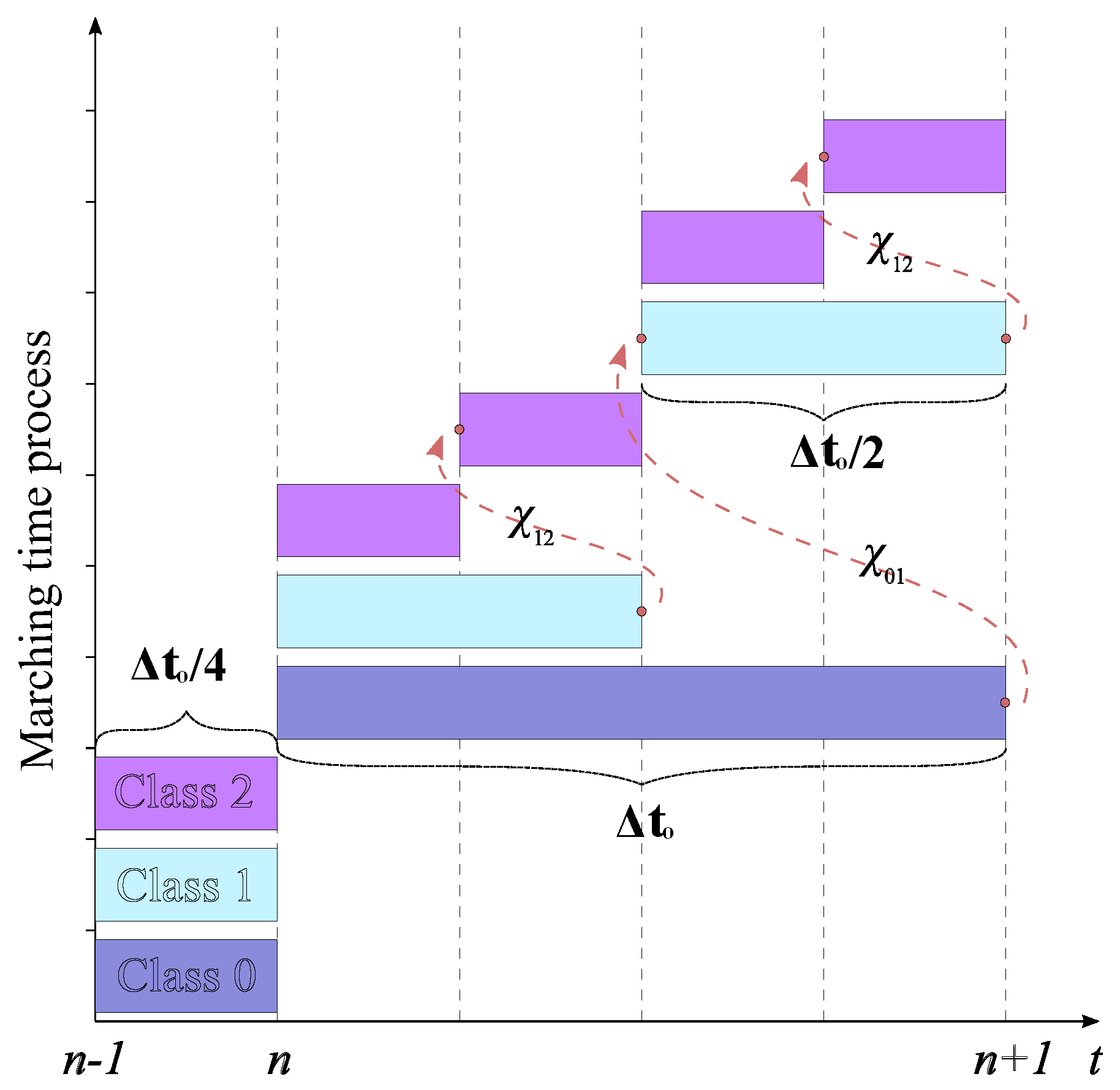
For a better understanding of the LTS procedure, let us consider a computational domain that, after a preprocessing stage, has been divided into three different element classes, and the interface elements between these classes have been identified. An illustration of this scheme is shown in Figure 1. Additionally, the corresponding time step values were chosen as Δ t 0 = 2 Δ t 1 = 4 Δ t 2 from the class with the largest time step to the class with the smallest time step, respectively. Once the time step values are defined, the time-marching process is performed recursively, starting from the class with the largest time step to the class with the smallest, as shown in Figure 2. However, at the interfaces between two elements belonging to two different classes, the interface values of the large element class are unknown. In order to ensure the continuity of the time solution at this interface and the same order of precision provided by the RK3 method, a third-order polynomial, χ , is used to approximate the intermediate values of the large element class. More information about this LTS scheme can be found in [26]. The algorithm commences with the assumption that all elements are at the same time level t n . This can be achieved easily by advancing all the elements by using the time step for the class with smaller elements as the global time step. Finally, the time-marching process for advancing from t n to t n + 1 is summarized in Algorithm 1.
Algorithm 1 LTS RK3 procedure for multiple levels of refinement
Step 1: Update the fields in all classes and store appropriate data to calculate χ at the interfaces between different classes.
Step 2: Advance all class elements in time by using their own locally stable time step, starting with class 0 until class 2.
Step 3: Calculate the interpolating polynomial, χ 12 , at the interface between class 1 and class 2. Then, use it to advance class 2 in one local time step Δ t 0 / 4 . Now, class 1 and class 2 are at the same time level.
Step 4: Advance the elements in classes 1 and 2 with the local time steps Δ t 0 / 2 and Δ t 0 / 4 , respectively. To do this, calculate the interpolating polynomial, χ 01 , at the interface between class 0 and class 1. Now, class 0 and class 1 are at the same time level.
Step 5: Repeat step 3 and store the appropriate data to calculate χ at the interfaces between different classes. Now, all classes are at the same time level.
Step 6: Repeat steps 2–5.
In addition, the total number of elements in the mesh is always greater than the number of elements in the class interfaces. Therefore, the memory requirements are not considered excessive when compared with those of the classical RK3 method [26]. This LTS strategy presents a crucial advantage in terms of its implementation due to the time stepping process only needing to be modified for interface elements. Finally, both the intermediate stages of the RK3 method and the third-order polynomials can be calculated using element-wise operations that are easy to parallelize [18].

4. Parallel-GPU Implementation

Nowadays, GPUs can be seen as general-purpose processors for floating-point operations—in other words, pieces of hardware designed to perform many arithmetic operations taking advantage of their multiple cores. GPUs present an improvement in performance when compared to CPUs due to their low latency and high bandwidth. In this work, we focus on a GPU acceleration technique based on the CUDA platform applied to the DGTD method [20]. The CUDA programming model consists of a set of threads grouped into blocks that form a grid at the same time. Therefore, it is the responsibility of the programmer to guarantee a good distribution or organization of the threads depending on the problem. For this purpose, it is necessary to know the hierarchical structure of the threads and memory [25]. These threads can access data from multiple types of memory in the GPU during their execution. Global memory is very widely used because it is the largest-capacity memory on a GPU and all threads can access it. However, its main problem is its high latency. Shared memory can be used to solve this high latency problem. However, shared memory can only be accessed by the threads allocated in each block and not all the threads. In addition, the shared memory size on NVIDIA GPUs is equal to 64 KB, which is a disadvantage when compared to the global memory. In order to optimize a CUDA program, it is critical to achieve an optimal balance in the distributions of the threads in each block. NVIDIA GPUs have restrictions of 1024 threads per block and 65,536 blocks per grid dimension. Thus, it is necessary to establish a good distribution considering these restrictions. As can be seen in [18], there being a large number of threads in a block reduces the memory latency, but this feature also reduces the number of available registers. Therefore, NVIDIA recommends using blocks of 128 or 256 threads to obtain better latency values and increase the number of registers.

4.1. The DGTD on Graphic Processors

The parallel-GPU DGTD-GTS method (GPU-DGTD-GTS) can be divided naturally into three principal CUDA kernels [27]: first, the surface integral kernel, where the flux vectors P q k from Equation (11) are calculated; second, the volume integral kernel, where the RHS terms L ( q , t ) from Equation (12) are calculated [18]; and third, the time integration kernel, where the field components are updated in time using the RK3 method. The procedure of the GPU-DGTD-GTS method is summarized in Algorithm 2. The input arrays needed in Algorithm 2 are summarized in Table 1. These input arrays were calculated on the host (CPU) and then stored on the device (GPU) for use in the kernels. The variables N f c , K, and  D i m that appear in Table 1 are the number of field components, the number of elements in the mesh, and the spatial dimension, respectively. In addition, the geometric factors mentioned in Table 1 are the terms used in the transformation from the reference to the local element [4]. The data exchange between the host and the device is a critical issue in terms of time consumption. However, this operation is essential and cannot be omitted, as the field components must be updated at each time step to ensure accurate computation and maintain the data dependencies necessary for subsequent processing. Additionally, this data transfer is also important for post-processing tasks, which are typically handled on the CPU side. Therefore, it is recommended to minimize it as much as possible. Finally, most works in the literature recommend using shared memory as much as possible for computing calculations due to its lower latency and higher bandwidth [10,18,19]. The CUDA kernels used in Algorithm 2 are described as follows:
Algorithm 2 The GPU-DGTD-GTS method
procedure PAR_MAXWELL (q, G V , G S , LIFT, D i , Flux i n d )
   Initialize all variables and create update matrices Pq, rhsq
   Calculate the time step value Δ t
   Copy data from the CPU to the GPU
   Define the number of time steps N t s
   for k = 0 until Nts do//time loop
    for l = 0 until 2 do//RK 3 stages
      <surface_integral_Kernel> {Calculate p q }
      <volume_integral_Kernel> {Calculate rhs q }
      <time_integration_Kernel> {Update q}
    endfor
    Copy data from the GPU to the CPU
   endfor
   return q
end

4.1.1. The Surface Integral Kernel

The surface kernel, summarized in Algorithm 3, is used to calculate the terms P q shown in Equation (11). In this kernel, the number of threads and blocks is calculated depending on the number of elements and degrees of freedom (DOF) in the mesh. To do this, we use the principle of one thread for each node. According to [18], it is good practice to choose a number of threads per block between 64 and 128. Therefore, considering that each block processes the nodes of several elements, K f , the number of threads in each block is set to N f a c e s · N f p · K f . Consequently, the number of blocks must be defined as B l o c k s f = c e i l ( K / N f a c e s · N f p · K f ) . The use of the function c e i l implies a padding process to balance the load in all blocks. During the development of this kernel, numerical tests were conducted to compare the performance when using global and shared memory. The results showed no significant difference in the execution time between the two kernels, indicating that both shared memory and global memory are viable options for this task. This is because all the operations in the kernel are based on element-wise computations, which can be efficiently handled in global memory. Additionally, since all the threads have access to the global memory, applying boundary conditions is more straightforward when using it.
Algorithm 3 Surface integral kernel
procedure SUR_KERNEL (q, G S , Flux i n d , P q ) (
  for each block of elements B l o c k s f  do
     Calculate Δ q using q + = q [ Flux i n d + ] and q = q [ Flux i n d ]
     Apply boundary conditions to terms Δ q
     Use Δ q and G s to calculate Equation (11)
     Store the values in P q
  endfor
  return  P q
end

4.1.2. The Volume Integral Kernel

The volume kernel, summarized in Algorithm 4, is used to calculate the RHS terms L ( q , t ) in Equation (12). These RHS terms are calculated using matrix–vector multiplications for each element. Considering the principle of 1 thread per output and a number of threads between 64 and 128 per block [18], we define each block so that it processes the nodes of K v elements. Therefore, each block is responsible for N p · K v threads, and the number of blocks can be defined as B l o c k s v = c e i l ( K / N p · K v ) . Numerical tests conducted during the development of this kernel demonstrated an improvement in the execution time when shared memory was used. This is achieved by storing and loading the threads into shared memory in row-major order, as suggested in [25]. This ordering ensures that each thread accesses only one memory location per bank, avoiding the bank conflict problem and maximizing the memory bandwidth. Furthermore, the lower latency and higher memory bandwidth of shared memory make it a better option for boosting the performance of this kernel compared to global memory.

4.1.3. The Time Integration Kernel

In this kernel, time integration is performed by using the RK3 method, which can be summarized into element-wise operations between the RK coefficients [4] and the field components. The element-wise operations in this kernel are performed using the same distribution of the DOF presented in the volume integral kernel. According to [18], the time integration kernel is relatively simpler than the volume and surface integral kernels due to the field components only being used once during the calculations. Thus, it is not necessary to use shared memory. The procedure for the time integration kernel can be seen in Algorithm 5.

4.2. The GPU-DGTD-LTS Method

For the sake of convenience, only two element classes will be considered. c l a s s ( 0 ) contains all elements which will advance with a time step of Δ t 0 and c l a s s ( 1 ) all elements which will advance with a time step of Δ t 0 / 2 . It is important to remark that the elements in c l a s s ( 1 ) are smaller than those in c l a s s ( 0 ) . The number of DOF distributions that must be established depends directly on the number of element classes to a factor of D O F D = N c l a s s e s + 1 . That is, we must establish a DOF distribution for each class and one more for the entire computational domain. This additional DOF distribution is needed to start Algorithm 1, which requires all the elements to advance in time at a global time step from t n 1 to t n . The DOF distribution for each kernel considering the entire computational domain was presented in the previous subsection. Next, the DOF distribution for the other two classes is discussed in more detail. When the computational domain is split into two classes, many new parameters must be considered. For  c l a s s ( 0 ) , we can extract, for example, K c 0 , which contains the information on the interior elements, and K c 0 i , which contains the information on the large interface elements. These parameters can also be extracted for c l a s s ( 1 ) ; we have called them K c 1 and K c 1 i . Given that these parameters are different for each class, it is necessary to create a DOF distribution for each class individually. However, we notice that even with different DOF distributions, there are some parameters that remain constant—for example, the number of nodes in each element N p and the number of face nodes N f p . This feature makes the DOF distribution process presented in the previous subsection very suitable for reuse with few changes.
Algorithm 4 Volume integral kernel
procedure VOL_KERNEL (q, G v , D i , LIFT, P q , r h s q )
  for each block of elements B l o c k s v , do
     Send arrays q , G v , D i , to shared memory
     for each element K v of each block B l o c k s v , do
      Load geometric factor from G v
      Load field components from q
      Load differentiation matrices from D i
      Calculate field derivatives and store in r h s q
     endfor (
     Obtain r h s q from shared memory and store in global memory
     Send arrays r h s q , L I F T , P q to shared memory
     for each element K v of each block B l o c k s v , do
      Load flux vectors from P q
      Load the L I F T matrix
      Load r h s q
      Multiply L I F T × P q and store in a temporal array
      Update r h s q using r h s q = r h s q + temporal array
     endfor
     Obtain r h s q from shared memory and store in global memory
  endfor
  return  r h s q
end
Algorithm 5 Time integration kernel
procedure TIME_KERNEL (q, rhs q , Δ t )
  for each block of elements B l o c k s v  do
     Define the RK3 constant coefficients of stage ( a i j , b i , c i ) [4]
     Update term q using q = q + r h s q · R K c o e f f i c i e n t s · Δ t
  endfor
  return  q
end
Suppose that we are going to establish the DOF distribution for c l a s s ( 0 ) in the GPU. According to Algorithm 2, the first CUDA kernel that will be executed is the surface integral kernel. This kernel is used to calculate the flux vectors P q 0 for  c l a s s ( 0 ) . In this case, we maintain the same number of threads per block, N f a c e s · N f p · K f , as in the previous case but modify the number of blocks by B l o c k s f 0 = c e i l ( K c 0 / N f a c e s · N f p · K f ) . Note that this DOF distribution for the flux kernel in c l a s s ( 0 ) uses the same number of threads per block as in the global case. However, a difference appears when calculating the total number of blocks because the number of elements in c l a s s ( 0 ) , K c 0 , differs from the total number of elements in the mesh, K. The DOF distribution for the volume integral kernel in c l a s s ( 0 ) is established by considering the same number of threads per block N p · K v as in the global case but modifying the number of blocks by B l o c k s v 0 = c e i l ( K c 0 / N p · K v ) . This DOF distribution can be also used in the time integration kernel. At this point, the DOF distributions for the elements in c l a s s ( 0 ) are established. Note that we basically use the same methodology proposed for the global problem with some simple modifications. This represents an interesting advantage of our proposed method because the routines for the DOF distributions can be used recursively. Hence, for the DOF distributions of c l a s s ( 1 ) , we follow the same procedure as previously described, only substituting the parameter K c 0 with K c 1 .
Finally, we have to handle the calculation of the third-order interpolating polynomial, χ 01 i , used in the calculation in the intermediate stages of the LTS RK3 method. For this, we create one more CUDA kernel which will be responsible for these calculations. As mentioned before, the equation for calculating the interpolating polynomial can be represented by elementary operations that include simple arithmetic operations between vectors and constants [26]. Additionally, it is easy to see that the interpolating polynomial χ 01 i will have a size of N p × K c 0 i . Therefore, the same DOF distribution considered in the volume kernel can be reused to organize the threads and blocks in this kernel. The procedure for implementing the GPU-DGTD-LTS method is summarized in Algorithm 6. It was developed by taking Algorithm 2 into consideration. It is worth remembering that only two different element classes were considered. However, this concept can be extended to considering multiple levels of refinement.
Algorithm 6 GPU-DGTD-LTS method
procedure PAR_LTS_MAXWELL (q, G V , G S , LIFT, D i , Flux i n d )
  Extract class(0) information {Calculate q0, G V 0 , G S 0 , Flux i n d 0 }
  Extract class(1) information {Calculate q1, G V 1 , G S 1 , Flux i n d 1 }
  Initialize update matrices { P q 0 , r h s q 0 , P q 1 , r h s q 1 }
  Calculate the time step values for class(0), Δ t 0 , and class(1), Δ t 1
  Copy data from the CPU to the GPU
  Define the number of time steps N t s {calculated using Δ t 0 }
  Advance by one global time step and store the appropriate data
  for k = 0 until Nts, do//time loop
     for l = 0 until 2, do//RK3 for class(0)
        <surface_integral_Kernel_C0> {Calculate P q 0 }
        <volume_integral_Kernel_C0> {Calculate r h s q 0 }
        <time_integration_Kernel_C0> {Update q0}
     endfor
     Update q using q0
     Calculate the interpolating polynomial χ to advance in class(1)
     for j = 0 until 1, do//two refinement levels
        for l = 0 until 2, do//RK3 for class(1)
           <surface_integral_Kernel_C1> {Calculate P q 1 }
           <volume_integral_Kernel_C1> {Calculate r h s q 1 }
           <time_integration_Kernel_C1> {Update q1}
        endfor
     endfor
     Update q using q1
     Copy data from the GPU to the CPU
  endfor
  return q
end
It is important to highlight that both Algorithms 2 and 6 are based on the same GPU algorithm described in Section 4.1. At first glance, Algorithm 6 is more complex than Algorithm 2 in terms of the number of operations required to update the field components q. Furthermore, introducing two loops into the LTS code implies an increase in the execution time, which is counterproductive in terms of efficiency. However, the computational gain in Algorithm 6 is achieved due to the decrease in the number of time steps N t s provided for the LTS scheme. For example, let us suppose that the program will need 2000 time steps to be executed and this number of time steps is calculated using the smallest element in the mesh. Additionally, we know a priori that the domain can be divided into two classes. The first class contains the large elements that can advance with a time step value of Δ t 0 , and the second class contains the small elements that can advance with a time step value of Δ t 1 . This time step values are related as follows: Δ t 0 = 2 Δ t 1 . Under a global time step scheme, the field components for each element are computed 2000 times (i.e., using the time step for the second class, Δ t 1 , based on the smallest element in the mesh). In contrast, in our LTS scheme, the field components for each element in the first class are computed 1000 times, while those in the second class are computed 2000 times.

5. Numerical Results

In this section, we propose three numerical examples to demonstrate the accuracy and efficiency of the proposed parallel-GPU DGTD method with a third-order LTS scheme. All calculations were run on the computer with 16 GB of RAM, a RYZEN 7 5800H CPU, and a GTX 1650-4 GB GPU.

5.1. A Metallic Cavity Benchmark Problem

In order to validate our implementation in terms of numerical convergence and computational gain, we use the metallic air-filled cavity problem shown in [4]. The computational domain Ω is a 2 × 2 m2 square centered at the origin. The material inside the cavity is considered a vacuum, with ε r = μ r = 1 . In addition, the walls of the cavity are considered to be made of perfect electric conductor (PEC) material. Therefore, the tangential components of the electric field, E z , must be vanished at the boundary of the domain. In this problem, we use a set of different unstructured triangular meshes whose characteristics are summarized in Table 2. These meshes were successively refined by a factor of 2 to the maximum edge size factor h. The computational domain is divided into two different classes. C l a s s ( 0 ) contains the large elements, and C l a s s ( 1 ) contains the smaller elements. Information about the number of elements in each class and the number of large interface elements is shown in Table 2. The time step for both classes is calculated individually by applying Equation (13) considering C = 1 . These time step values for both classes in each mesh are shown in Table 2. According to [26], this LTS algorithm provides a convergence rate of ≈3 when N = 2 . Therefore, we set the order of the basis functions as two. This order impacts the number of threads due to the variables N f p and N p . As mentioned before, the number of threads remains constant while the number of blocks depends on the number of elements. In this case, the values K f and K v are set to 14 and 21, respectively. Thus, the number of threads in the surface kernel is N f a c e s × N f p × K f = 3 × 3 × 14 = 126 , and in the volume kernel, it is N p × K v = 6 × 21 = 126 .
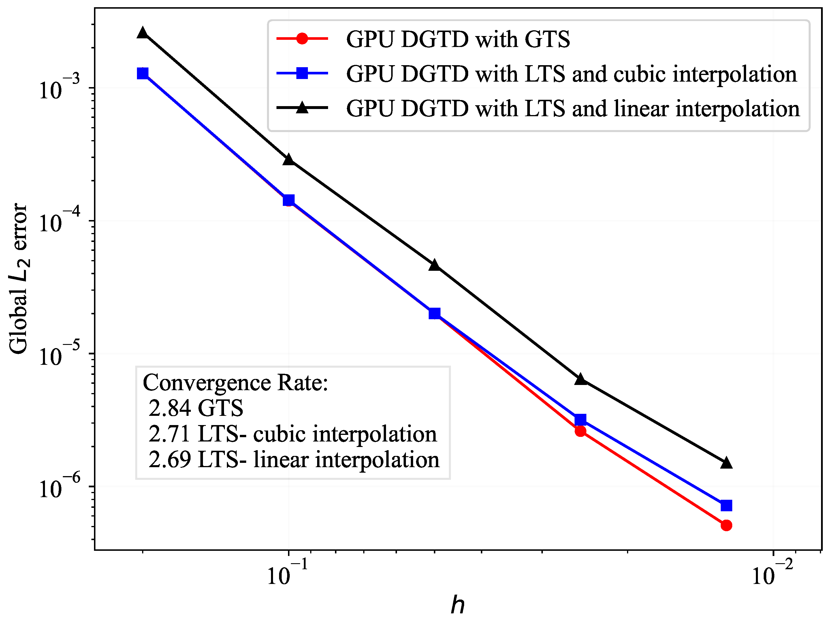
Comparisons in terms of the global error using the L 2 norm and the convergence rate between the GPU-DGTD-GTS and GPU-DGTD-LTS methods can be seen in Figure 3. This figure also illustrates the results of the LTS scheme using both linear and cubic interpolation in order to show the impact of high-order interpolation on the accuracy of the method. All errors were calculated at time t = 33.333 ns. As can be seen in Figure 3, the GPU-DGTD-GTS method ensures a convergence rate of 2.84, as expected from the RK3 method. On the other hand, the results of our proposal with linear and cubic interpolation show a small loss of precision and consequently a small loss in the convergence rate, obtaining values of 2.69 and 2.71, respectively, when compared with standard GTS. This loss of precision was expected due to the error introduced by the first-order and third-order interpolations. Note that even with a loss of precision, the approximated solution maintains the same order of precision for each mesh. This test shows that the order of the interpolation impacts directly the accuracy of the LTS scheme but does not affect the convergence rate. In addition, we found that this LTS algorithm does not provide a computational gain in the first three meshes when compared with GTS. Thus, there is no advantage in applying this formulation in a computational domain with few elements. The results become interesting when the number of elements in the computational domain is increased. To calculate an estimate of the maximum theoretical computational gain in applying the LTS algorithm, a finer mesh is chosen. In this mesh, there are 6580 elements that advance with the smallest time step, Δ t 0 / 2 , and 66,936 that advance with the largest time step, Δ t 0 . Thus, completing one time cycle of size Δ t 0 requires ( 6580 ) 2 + 66,936 = 80,096 element time steps. On the other hand, for the global time step scheme to complete one time cycle of size Δ t 0 , (6580 + 66,936) ∗ 2 = 147,032 element time steps are required. The ratio between these numbers is 147,032/80,096 ≈ 1.8. Therefore, the theoretical maximum computational gain expected for the application of the LTS method in this problem is represented by this ratio. The execution time in mesh 5 for the GTS, LTS with linear interpolation, and LTS with cubic interpolation implementations was 118.701 s, 80.66 s, and 81.05 s, respectively. Note that the difference between the execution time for the LTS with linear and cubic interpolation was minimal, demonstrating that cubic interpolation is the best choice in terms of accuracy and efficiency. The acceleration in comparing using GTS and LTS with cubic interpolation strategies was 1.46 , which is close to the optimal value of 1.8 . The difference between these ratios is caused by the increase in the data exchange between the CPU and the GPU in implementing the LTS algorithm and the calculation of the interpolating polynomials.

5.2. Scattering by a PEC Sphere

This test problem is studied with the purpose of evaluating the accuracy and efficiency of the proposed GPU-DGTD-LTS method when dealing with near-field and far-field quantities in an electromagnetic scattering problem. In this case, a PEC sphere inside a vacuum background is illuminated by an x-polarized incident plane wave propagating in the z ^ direction. The computational domain Ω is composed of a r 1 = 0.5 m radius PEC sphere bounded by a cube with a side length of Ω a = 3 m centered at the point (0, 0, 0). Figure 4 shows a cross-sectional view of the geometry in the x z plane when y = 0 . The problem is truncated using a PML absorbing boundary condition with a thickness of 0.5 m in the x ^ , y ^ and z ^ directions. The incident plane wave is introduced by using the Huygens principle and the total-field/scattered-field (TF/SF) formulation [28]. The waveform for the incident plane wave is defined as follows:
g ( t ) = cos ( 2 π f t ) exp ( t 2 / τ 2 )
where f = 300 MHz is the central frequency, and τ = 0.33 ns is a time constant.
The tetrahedral mesh is composed of 116,249 elements of a second-degree polynomial order. This mesh was generated considering a maximum edge size factor h = λ / 20 , where λ is the wavelength, which depends on the speed of light and the central frequency. In this test problem, three different classes were used for the time stepping scheme. The number of elements in C l a s s ( 0 ) , C l a s s ( 1 ) , and C l a s s ( 2 ) is 54,549, 4465, and 57,235, respectively. The time step values Δ t 0 = 7.8 ps, Δ t 1 = 3.9 ps, and Δ t 2 = 1.95 ps were calculated for each class considering Equation (13) with C = 1 . Finally, the simulation was performed for 17 ns.
To illustrate the importance of high-order interpolations in an LTS scheme, the E field was sampled at a critical point in the domain and compared to the standard GTS implementation. This critical point was located at the interface between two neighboring classes, where the interpolations were performed. Figure 5 shows the E field components x, y, and z over the simulation time. As shown, first-order interpolation introduces oscillations and amplitude errors, which are mitigated by third-order interpolation. Table 3 presents the maximum error values produced by the LTS method with first-order and third-order interpolation compared to those of the standard GTS approach. These results indicate that even in the worst case, the LTS method with a third-order interpolation scheme can closely match the standard GTS solution, with a maximum error of 2.4 × 10 3 in the E x component. In contrast, the first-order LTS method, while providing a reasonable approximation to the GTS solution, exhibits reduced precision, resulting in a maximum error of 1.3 × 10 1 in the E z component. This difference arises because the third-order scheme incorporates additional values to enhance the continuity between classes, leading to a smoother solution with fewer errors. These preliminary results demonstrate that high-order interpolation in an LTS scheme is not just a formality but a necessity, as lower-order interpolation can compromise the accuracy of the method.
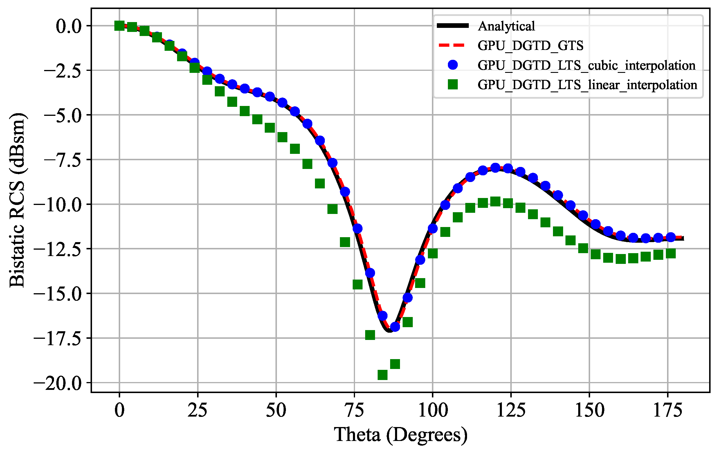
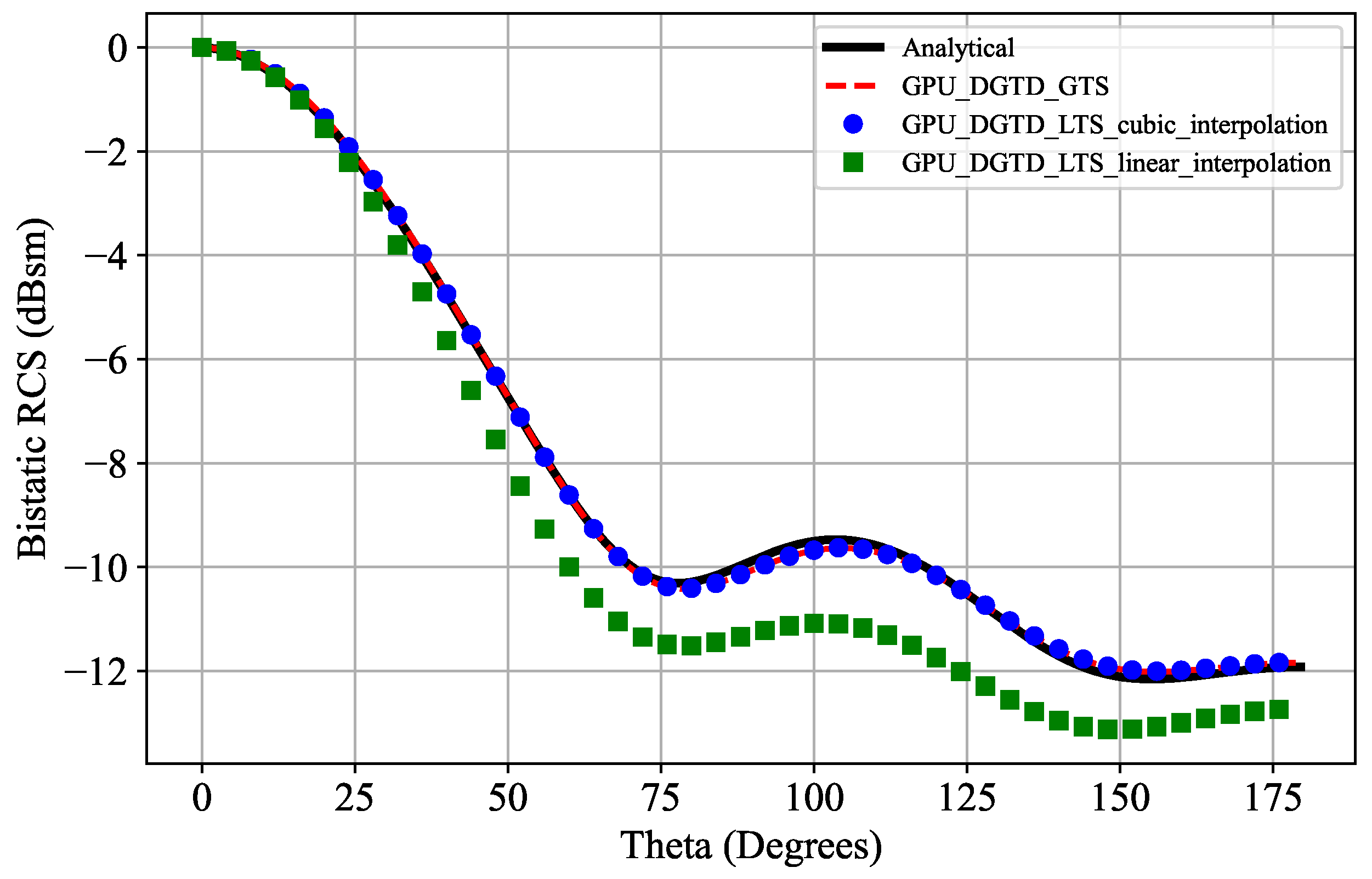
The bistatic Radar Cross-Section (RCS) is a crucial far-field parameter in electromagnetic scattering problems and is frequently employed for the verification of numerical methods. In addition, it is essential to understand the impact of first-order and cubic interpolations on far-field quantities. Consequently, the RCS was calculated and plotted in both the E-plane and H-plane, as depicted in Figure 6 and Figure 7. The bistatic RCS is calculated by using the near-field/far-field (NF/FF) formulation at 300 MHz. These results were compared with the analytical solution and the GPU-DGTD-GTS method. As illustrated in Figure 6 and Figure 7, both the proposed GPU-DGTD-LTS method with cubic interpolation and the standard GPU-DGTD-GTS method demonstrate good agreement with the analytical solution. On the other hand, while the GPU-DGTD-LTS method with linear interpolation produces RCS values close to those of the analytical solution, amplitude errors are still present. This discrepancy is anticipated, as the far-field parameters are directly influenced by the near-field values. Table 4 summarizes the results in terms of the execution time, the relative error of the RCS, and the speed-up. As in the previous problem, the execution time difference between the LTS schemes with first-order and cubic interpolation is negligible. In this case, the time reduction for both LTS implementations was almost 60% when compared with the standard GPU-GTS case. Furthermore, the LTS scheme with cubic interpolation maintained the same order of precision as the standard case, proving to be the best choice for solving electromagnetic scattering problems.

5.3. Scattering by a Multilayer Dielectric Sphere

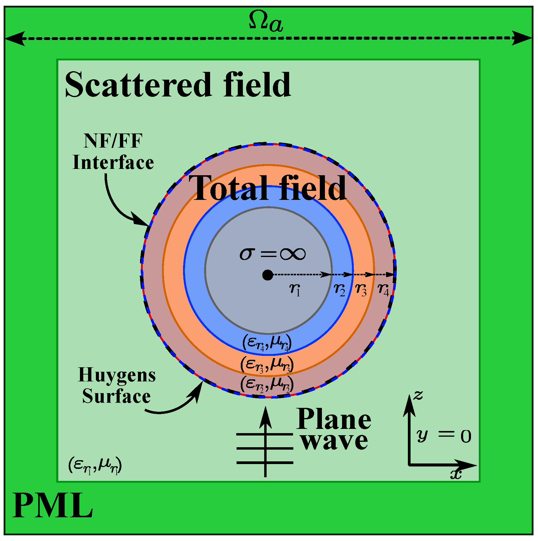
In order to show the performance of our proposal in more complex and multi-scale problems, we chose to study scattering by a multilayer dielectric sphere [29]. This problem is ideal for exploring the flexibility of the DGTD method in handling complex geometries and unstructured meshes. The multi-scale nature of this problem enabled us to leverage the proposed GPU-DGTD-LTS method with third-order interpolation, dividing the problem into several classes based on the size of the elements or the electromagnetic parameters of the media. It significantly improved the computational efficiency, especially in regions that required a fine spatial resolution. The problem consisted of four concentric spheres, with the innermost sphere modeled as a PEC material and the remaining spheres modeled as dielectric materials. The geometry of the problem is depicted in Figure 8, where a cross-sectional view of the x z plane can be seen when y = 0 . The computational domain Ω is bounded by a cube with a side length of Ω a = 3 m centered at ( 0 , 0 , 0 ) . The PML boundary condition was used, with a thickness of 0.5 m in all directions, that is, the real computational domain was 2 3  m3. The region outside the multilayer sphere was assumed to be a vacuum, with μ r 1 = ε r 1 = 1 . The materials in the multilayer regions were assumed to be linear, isotropic, and non-magnetic, with relative permittivity of ε r 2 = 2 , ε r 3 = 3 , and ε r 4 = 4 . The radii of the spheres, from the innermost to the outermost, were r 1 = 0.3 m, r 2 = 0.4 m, r 3 = 0.5 m, and r 4 = 0.6 m, respectively. The incident x-polarized plane wave propagating in the z ^ direction was inserted by using the TF/SF formulation and was modeled using the same expression as in Equation (14) with f = 300 MHz and τ = 0.33 ns.
The computational domain consists of a tetrahedral mesh made of 193,627 elements with a second-degree polynomial basis, which corresponds to more than 1.9 million DOF for each field component. This domain was built considering a maximum edge size factor h = λ / 20 in each class. In this case, the time stepping scheme was used with four different classes. C l a s s ( 0 ) , C l a s s ( 1 ) , C l a s s ( 2 ) and C l a s s ( 3 ) contain 44.7%, 13.6%, 21.6%, and 20.1% of the elements, respectively. The time step values used in the time-marching process were defined as Δ t 0 = 5.28 ps, Δ t 1 = 2.64 ps, Δ t 2 = 1.32 ps, and Δ t 3 = 0.66 ps. These time step values were calculated using Equation (13) with C = ( 1 / 2 ) . Finally, the simulation was carried out for 50 ns.
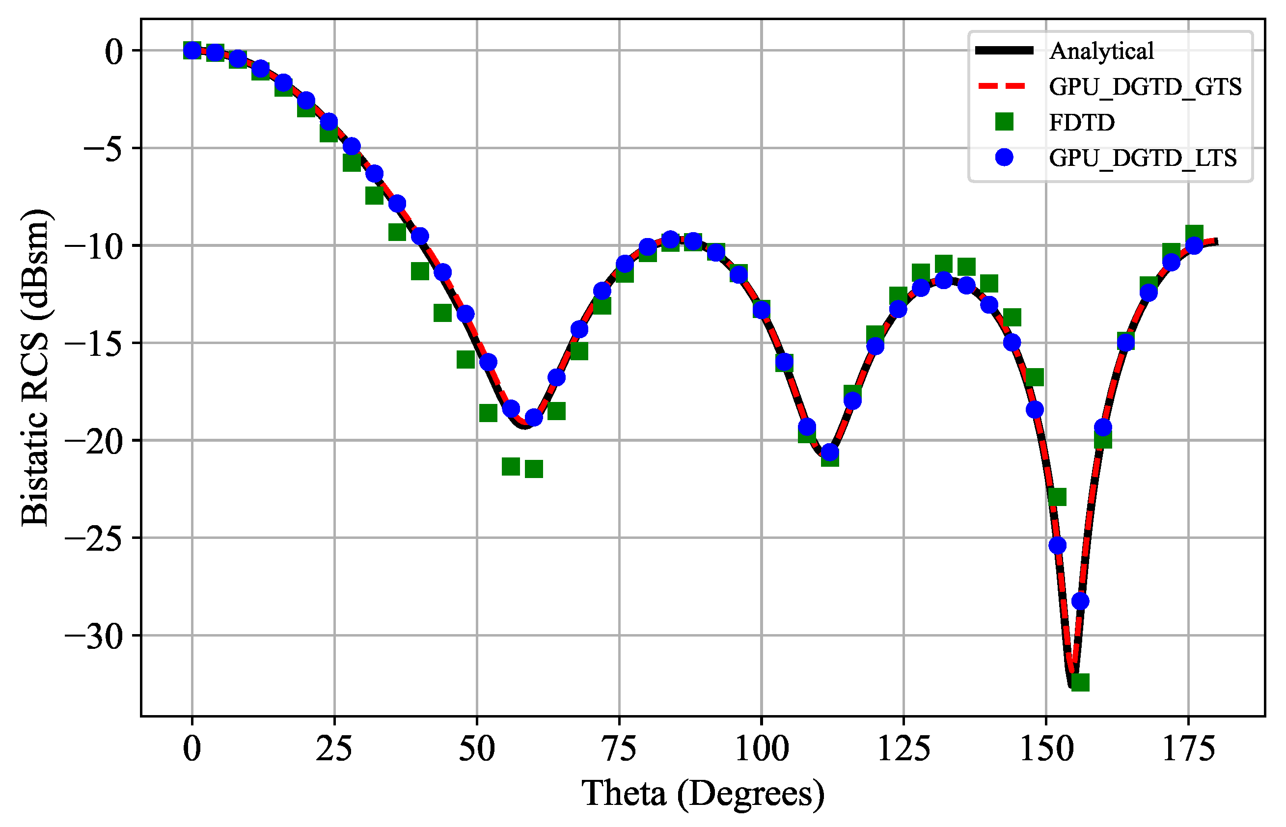
As in the PEC sphere problem, the accuracy of the method was verified by calculating the RCS at 300 MHz in the E-plane and the H-plane. These results were compared with those of the analytical solution, the standard GPU-DGTD-GTS method, and the second-order FDTD method [28], as shown in Figure 9 and Figure 10. The FDTD method was included in this analysis because its computational simplicity and accurate results make it a common choice for solving electromagnetic scattering problems in the time-domain. Figure 9 and Figure 10 confirm that the proposed GPU-DGTD-LTS method with third-order interpolation provides excellent results when compared with the analytical solution and its GTS counterpart. On the other hand, although the FDTD results show good agreement with those of the analytical solution, there are small discrepancies, which may be related to the significant restriction of dealing with cube-based space partitioning making it difficult to accurately represent the curvatures in the problem. It is important to remark that the FDTD results were obtained under conditions similar to those of the DGTD case but using a fine grid discretization of Δ x = Δ y = Δ z = λ / 100 . The results in terms of the execution time, the relative error of the RCS, and the speed-up for the DGTD and FDTD implementations are shown in Table 5. The results in terms of the execution time show a very interesting improvement for the LTS case, achieving a reduction of almost 78% when compared with the standard GPU-DGTD-GTS method. Similarly to the previous problem, the error values with the GPU-DGTD-LTS method show a slight loss of precision compared to those of its GTS counterpart while maintaining the same order of accuracy. Furthermore, the error values for the FDTD implementation are almost twice as large as those for the DGTD. This can be attributed to the inability to accurately represent the curvatures in the problem even if a fine grid model is used. Finally, the execution time and speed-up results for the FDTD method were not included in this table because there is no direct comparison between them and the DGTD algorithms described.

6. Conclusions

This work presented an alternative to the common GPU-DGTD-LTS approaches based on second-order methods and first-order interpolation. In our strategy, we sought to ensure the accuracy of the LTS RK3 time integration method using third-order interpolations. First, a global DOF distribution for the CUDA kernels in the GPU-DGTD-GTS method was shown. We then adapted the global DOF distribution process to handling two, three, and four different element classes, reusing the same methodology recursively. For the third-order interpolations, an efficient CUDA kernel was also developed. These DOF distributions were established based on NVIDIA’s recommendations to ensure the optimal GPU performance. To validate our proposal, we solved 2D and 3D electromagnetic wave problems and presented the results in terms of accuracy and efficiency. The numerical results for the metallic cavity problem demonstrate that the convergence rate of our proposed GPU-DGTD-LTS method is not affected by the order of the interpolation. However, the best accuracy was obtained with cubic interpolation, as expected. In addition, a computational gain of nearly 32% for the finer mesh was achieved compared with the GTS version. On the other hand, the PEC sphere problem revealed that the interpolation order directly impacts the accuracy of the proposed LTS scheme in computing both the near-field and far-field quantities when solving an electromagnetic scattering problem. Furthermore, these results demonstrate that our proposed GPU-DGTD-LTS method with cubic interpolation ensures an indistinguishable accuracy when compared to that of standard GTS but provides an attractive speed-up of greater than 2.4 or equivalent, reducing the execution time by almost 60%. Finally, for the multilayer sphere problem, we again observed a small loss of accuracy due to the interpolation when comparing the LTS and GTS versions. However, this loss of accuracy was non-significant in comparison to the computational gain of 78% between the GPU implementations, demonstrating that this approach is also recommended for solving more complex multi-scale electromagnetic problems.

Author Contributions

Conceptualization, M.J.L. and E.J.S.; methodology, M.J.L. and E.J.S.; software, M.J.L.; validation, M.J.L.; investigation, M.J.L.; resources, M.J.L.; writing—original draft preparation, M.J.L.; writing—review and editing, E.J.S.; visualization, M.J.L.; supervision, E.J.S.; project administration, E.J.S. All authors have read and agreed to the published version of the manuscript.

Funding

This study was financed in part by the Coordenação de Aperfeiçoamento de Pessoal de Nível Superior—Brasil (CAPES)—Finance Code 001 and the Brazilian agencies FAPEMIG and CNPq.

Data Availability Statement

The data will be made available by the authors on request.

Conflicts of Interest

The authors declare no conflicts of interest.

References

  1. Li, J. Development of discontinuous galerkin methods for maxwell’s equations in metamaterials and perfectly matched layers. J. Comput. Appl. Math. 2011, 236, 950–961. [Google Scholar] [CrossRef]
  2. Mi, J.; Ren, Q.; Su, D. Parallel subdomain-level dgtd method with automatic load balancing scheme with tetrahedral and hexahedral elements. IEEE Trans. Antennas Propag. 2021, 69, 2230–2241. [Google Scholar] [CrossRef]
  3. Wang, Y.; Zhao, R.; Huang, Z.; Wu, X. A verlet time-stepping nodal dgtd method for electromagnetic scattering and radiation. In Proceedings of the 2019 IEEE International Conference on Computational Electromagnetics (ICCEM), Shanghai, China, 20–22 March 2019; pp. 1–3. [Google Scholar] [CrossRef]
  4. Hesthaven, J.S.; Warburton, T. Nodal Discontinuous Galerkin Methods: Algorithms, Analysis, and Applications; Springer: New York, NY, USA, 2008. [Google Scholar]
  5. Ban, Z.G.; Shi, Y.; Wang, P. Advanced Parallelism of DGTD Method with Local Time Stepping Based on Novel MPI + MPI Unified Parallel Algorithm. IEEE Trans. Antennas Propag. 2022, 70, 3916–3921. [Google Scholar] [CrossRef]
  6. Wen, P.; Kong, W.; Hu, N.; Wang, X. Efficient Analysis of Radio Wave Propagation for Complex Network Environments Using Improved DGTD Method. IEEE Trans. Antennas Propag. 2024, 72, 5923–5934. [Google Scholar] [CrossRef]
  7. Yáñez-Casas, G.A.; Couder-Castañeda, C.; Hernández-Gómez, J.J.; Enciso-Aguilar, M.A. Scattering and Attenuation in 5G Electromagnetic Propagation (5 GHz and 25 GHz) in the Presence of Rainfall: A Numerical Study. Mathematics 2023, 11, 4074. [Google Scholar] [CrossRef]
  8. Fang, X.; Zhang, W.; Zhao, M. A Non-Traditional Finite Element Method for Scattering by Partly Covered Grooves with Multiple Media. Mathematics 2024, 12, 254. [Google Scholar] [CrossRef]
  9. Sheng, Y.; Zhang, T. A Finite Volume Method to Solve the Ill-Posed Elliptic Problems. Mathematics 2022, 10, 4220. [Google Scholar] [CrossRef]
  10. Shi, Y.; Wang, P.; Ban, Z.G.; Zhu, S.C. Application of Hybridized Discontinuous Galerkin Time Domain Method into the Solution of Multiscale Electromagnetic Problems. In Proceedings of the 2019 Photonics & Electromagnetics Research Symposium-Fall (PIERS-Fall), Xiamen, China, 17–20 December 2019; pp. 2325–2329. [Google Scholar] [CrossRef]
  11. Piperno, S. Symplectic local time-stepping in non-dissipative dgtd methods applied to wave propagation problems. ESAIM Math. Model. Numer. Anal. 2006, 40, 815–841. [Google Scholar] [CrossRef]
  12. Montseny, E.; Pernet, S.; Ferrieres, X.; Cohen, G. Dissipative terms and local time-stepping improvements in a spatial high order discontinuous galerkin scheme for the time-domain maxwell’s equations. J. Comput. Phys. 2008, 227, 6795–6820. [Google Scholar] [CrossRef]
  13. Cui, X.; Yang, F.; Gao, M. Improved local time-stepping algorithm for leap-frog discontinuous galerkin time-domain method. IET Microw. Antennas Propag. 2018, 12, 963–971. [Google Scholar] [CrossRef]
  14. Trahan, C.J.; Dawson, C. Local time-stepping in runge–kutta discontinuous galerkin finite element methods applied to the shallow-water equations. Comput. Methods Appl. Mech. Eng. 2012, 217–220, 139–152. [Google Scholar] [CrossRef]
  15. Angulo, L.; Alvarez, J.; Teixeira, F.; Pantoja, M.; Garcia, S. Causal-path local time-stepping in the discontinuous galerkin method for maxwells equations. J. Comput. Phys. 2014, 256, 678–695. [Google Scholar] [CrossRef]
  16. Li, M.; Li, X.; Xu, P.; Zhang, Y.; Shi, Y.; Wang, G. A Multi-scale Domain Decomposition Strategy for the Hybrid Time Integration Scheme of DGTD Method. In Proceedings of the 2024 International Applied Computational Electromagnetics Society Symposium (ACES-China), Xi’an, China, 16–19 August 2024; pp. 1–3. [Google Scholar] [CrossRef]
  17. Reuter, B.; Aizinger, V.; Kostler, H. A multi-platform scaling study for an OpenMP parallelization of a discontinuous Galerkin ocean model. Comput. Fluids 2015, 117, 325–335. [Google Scholar] [CrossRef]
  18. Zhao, L.; Chen, G.; Yu, W. GPU Accelerated Discontinuous Galerkin Time Domain Algorithm for Electromagnetic Problems of Electrically Large Objects. Prog. Electromagn. Res. B 2016, 67, 137–151. [Google Scholar] [CrossRef]
  19. Chen, H.; Zhao, L.; Yu, W. GPU Accelerated DGTD Method for EM Scattering Problem from Electrically Large Objects. In Proceedings of the 2018 Cross Strait Quad-Regional Radio Science and Wireless Technology Conference (CSQRWC), Xuzhou, China, 21–24 July 2018; pp. 1–2. [Google Scholar] [CrossRef]
  20. Feng, D.; Liu, S.; Wang, X.; Wang, X.; Li, G. High-order GPU-DGTD method based on unstructured grids for gpr simulation. J. Appl. Geophys. 2022, 202, 104666. [Google Scholar] [CrossRef]
  21. Einkemmer, L.; Moriggl, A. A Semi-Lagrangian Discontinuous Galerkin Method for Drift-Kinetic Simulations on GPUs. SIAM J. Sci. Comput. 2024, 46, B33–B55. [Google Scholar] [CrossRef]
  22. Ban, Z.G.; Shi, Y.; Yang, Q.; Wang, P.; Zhu, S.C.; Li, L. Gpu-accelerated hybrid discontinuous galerkin time domain algorithm with universal matrices and local time stepping method. IEEE Trans. Antennas Propag. 2020, 68, 4738–4752. [Google Scholar] [CrossRef]
  23. Li, M.; Wu, Q.; Lin, Z.; Zhang, Y.; Zhao, X. Novel parallelization of discontinuous galerkin method for transient electromagnetics simulation based on sunway supercomputers. Appl. Comput. Electromagn. Soc. J. 2022, 37, 795–804. [Google Scholar] [CrossRef]
  24. Li, M.; Wu, Q.; Lin, Z.; Zhang, Y.; Zhao, X. A minimal round-trip strategy based on graph matching for parallel dgtd method with local time-stepping. IEEE Antennas Wirel. Propag. Lett. 2023, 22, 243–247. [Google Scholar] [CrossRef]
  25. Cheng, J.; Grossman, M.; Mckercher, T. Professional CUDA C Programming; Wrox: Indianapolis, IN, USA, 2014. [Google Scholar]
  26. Ashbourne, A. Efficient Runge-Kutta Based Local Time-Stepping Methods. Master’s Dissertation, Department of Applied Mathematics, University of Waterloo, Ontario, CA, USA, 2016. [Google Scholar]
  27. Klockner, A. High-Performance High-Order Simulation of Wave and Plasma Phenomena. Ph.D. Thesis, Department of Applied Mathematics, Brown University, Providence, RI, USA, 2010. [Google Scholar]
  28. Elsherbeni, A.Z.; Demir, V. The Finite-Difference Time-Domain Method for Electromagnetics with MATLAB Simulations; SciTech Pub: Sydney, Australia, 2009. [Google Scholar]
  29. Jin, J.-M. The Finite Element Method in Electromagnetics; John Wiley & Sons: Hoboken, NJ, USA, 2015. [Google Scholar]
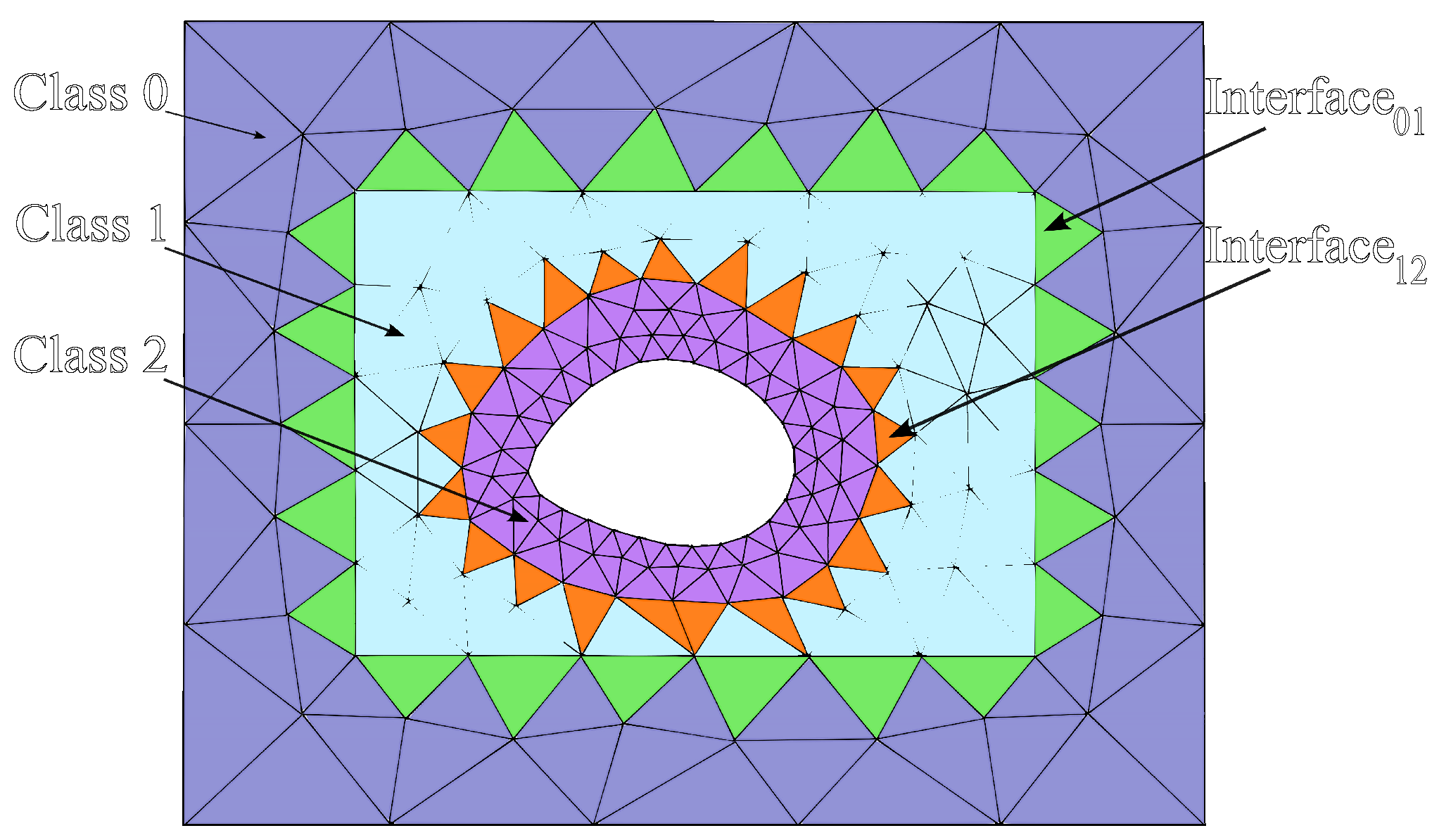
Figure 1. Example of a 2D computational domain after the LTS classification process.
Mathematics 12 03663 g001
Figure 2. LTS time-marching process from the class with the largest time step to the class with the smallest time step.
Mathematics 12 03663 g002
Figure 3. Convergence plot for the metallic cavity problem.
Mathematics 12 03663 g003
Figure 4. Cross-sectional view of the x z plane for the PEC sphere problem.
Mathematics 12 03663 g004
Figure 5. Cartesian components of electric field (a) Ex, (b), Ey, and (c) Ez for both GTS and LTS implementations at point (0.1, 0, 0.59).
Mathematics 12 03663 g005
Figure 6. The bistatic RCS for the PEC sphere problem in the E-plane ( ϕ = 0 ).
Mathematics 12 03663 g006
Figure 7. The bistatic RCS for the PEC sphere problem in the H-plane ( ϕ = 90 ).
Mathematics 12 03663 g007
Figure 8. Cross-sectional view of the x z plane for the multilayer sphere problem.
Mathematics 12 03663 g008
Figure 9. The bistatic RCS for the multilayer sphere problem in the E-plane ( ϕ = 0 ).
Mathematics 12 03663 g009
Figure 10. The bistatic RCS for the multilayer sphere problem in the H-plane ( ϕ = 90 ).
Mathematics 12 03663 g010
Table 1. List of input arrays for Algorithm 2.
ArrayDimensionDescription
q N f c · N p · K Field components
G V K · D i m 2 Volume geometric factors
G S K · N f a c e s · ( D i m + 1 ) Surface geometric factors
L I F T N p · N f a c e s · N f p Surface integration matrix
D i N p · N p · D i m Differentiation matrices
Flux i n d K · N f p · 2 Global element indexes + and −
Table 2. Meshes used in the metallic air-filled cavity problem.
Mesh NumberM1M2M3M4M5
Max edge size—h (m)0.20.10.050.0250.0125
No. of elements3681352482218,35873,516
No. of vertices2057172492934037,079
Elements in class 03121224435616,67666,936
Elements in class 15612846616826580
Large interface elements16283264124
Δ t 0 —Class 0 (ps)41.5221.6411.125.682.78
Δ t 1 —Class 1 (ps)20.7610.825.562.841.39
Table 3. Maximum error values of E field components comparing the LTS approach to the standard GTS method.
DGTD Simulations Ex error Ey error Ez error
GPU-LTS-Cubic 2.4 ×  10 3 3.6 ×  10 4 3.8 ×  10 5
GPU-LTS-Linear 6.5 ×  10 2 7.9 ×  10 3 1.3 ×  10 1
Table 4. Results for the problem of scattering by a PEC sphere.
DGTD SimulationsExecution Time (s)E-PlaneerrorH-PlaneerrorSpeed-Up
GPU-GTS8220.00540.0025-
GPU-LTS-Cubic3390.00560.002592.42
GPU-LTS-Linear3340.02710.0422.46
Table 5. Results for the problem of scattering by a multilayer sphere.
Numerical MethodExecution Time (s)E-PlaneerrorH-PlaneerrorSpeedup
GPU-DGTD-GTS18,7800.00490.0044-
GPU-DGTD-LTS41500.00510.00474.52
FDTD-0.0110.0081-
Disclaimer/Publisher’s Note: The statements, opinions and data contained in all publications are solely those of the individual author(s) and contributor(s) and not of MDPI and/or the editor(s). MDPI and/or the editor(s) disclaim responsibility for any injury to people or property resulting from any ideas, methods, instructions or products referred to in the content.