Article

Mathematical Formulations for Predicting Pressure Drop in Solid–Liquid Slurry Flow through a Straight Pipe Using Computational Modeling

1
Department of Mechanical & Aerospace Engineering, Monash University, Clayton, VIC 3800, Australia
2
Department of Mechanical Engineering, Amity University Haryana, Gurugram 122413, India
3
Department of Mechanical Engineering, University of the Philippines Los Baños, College, Laguna 4031, Philippines
4
Department of Engineering and Architectural Studies, Ara Institute of Canterbury, Canterbury 8011, New Zealand
5
School of Innovation, Design and Technology, Wellington Institute of Technology, Wellington 5012, New Zealand
*
Author to whom correspondence should be addressed.
Mathematics 2024, 12(18), 2879; https://doi.org/10.3390/math12182879
Submission received: 24 July 2024 / Revised: 3 September 2024 / Accepted: 13 September 2024 / Published: 15 September 2024

Abstract

:
The study establishes two mathematical formulations to predict the pressure drop in a solid–liquid slurry flowing through a straight pipe. Employing the Eulerian–Eulerian RNG k-ε model, the computational investigation uses water as the carrier fluid and glass beads as solid particles. The analysis spans various particle sizes (d50 = 75–175 μm), volumetric concentrations (Cvf = 10–50%), and velocities (Vm = 1–5 m/s). The first model, developed using the MATLAB curve-fitting tool, is complemented by a second empirical equation derived through non-polynomial mathematical formulation. Results from both models are validated against existing experimental and computational data, demonstrating accurate predictions for d50 = 75–175 µm particles within a Reynolds number range of 20,000 ≤ Re ≤ 320,000.
MSC:
76-04; 76-05; 76-05; 76-11

1. Introduction

Solid transportation through pipelines is a widely practiced method across various industries like chemicals, cement, mining, food processing, and power generation. This approach offers several benefits, including efficient transport, minimal pollution, low accident rates, cost-effectiveness, and reduced maintenance as well as energy requirements. However, it also portrays some significant challenges, such as the need for substantial initial investment, ensuring a constant supply of water or other carrier fluids, and addressing the issue of pipeline wear and failure due to abrasion and corrosion [1,2]. In the realm of slurry transportation, two primary modes have traditionally been employed: pneumatic and hydraulic. The efficiency of slurry flow largely hinges on the design of the pipeline system. One critical factor in assessing this efficiency is the pressure drop, a concept that has been fundamental since the twentieth century. It plays a central role in determining how effectively slurry can be transported through the pipeline system [3].
O’Brien [4] and Rouse [5] were among the pioneers in predicting concentration distribution in open channel flow with low volumetric concentrations. However, the first documented attempt to predict pressure drop through experimental and mathematical methods was made by Durand et al. [6], using coal as the solid granular material for multiphase flow analysis. Based on Durand’s work, several other researchers delved into similar models. Zandi et al. [7] proposed a modified version of Durand’s [6] equation, which was based on approximately 1000 data points gathered from various publicly available sources. The experiment was conducted to find pressure drop due to frictional losses in slurry flow. The proposed correlation is specifically developed for graded sand and gravel particulates and does not include the gravitational effects of solids. Furthermore, in 1954, Worster et al. [8] made some modifications to the model, accounting for the gravitational effects in the transportation of coal–water slurry mixtures. Their correlations, however, were specific to mono-sized particles and did not consider the friction coefficient between the wall and particles when calculating pressure drop. It is also important to note that a mixture with soft solid particulates like coal is expected to have a higher pipe and machinery life. Conversely, for harder materials, it is highly recommended to periodically replace the piping system.
Turian et al. [9] conducted investigations covering various flow regimes, including stationary bed flow, saltation flow, heterogeneous flow, and homogeneous flow, by collecting a total of 2848 data points. These data were effectively correlated with experimental results regarding pressure drop. Newitt et al. [10] established a relationship for heterogeneous slurry containing coarse coal and sand particles flowing through a one-inch diameter pipeline. Their study applied a zero-slip boundary at the wall and assumed that the work was carried out due to solid particulates equaled energy dissipation. Additionally, Condolios et al. [11] reported that a wide range of particulate distributions could be achieved by using a weighted mean coefficient in Durand’s equation. In 1972, Bantin et al. [12] conducted experiments with glass slurry flow at high concentrations through vertical and horizontal pipelines. They observed that slurry flow in horizontal pipes is influenced by gravitational effects, with particulates showing a tendency to settle at low velocities. Particulates flowing at higher velocities at an average volume fraction exhibited output closer to the freely settled value. Moreover, Geldart et al. [13] developed a correlation to investigate the pressure drop for fine coal granules transported at room temperature through a straight pipeline with a diameter of 12.5 mm and a pipe length of approximately 105 m. The mean flow velocity of the transporting medium, which was gas, ranged from 0.8 to 10 m/s. Extensive experiments with 600 data points revealed that the mathematical model accurately predicted pressure drops. More recently, Gopaliya et al. [14] developed a correlation for predicting pressure drop in mild heterogeneous solid–liquid slurry flow from a straight horizontal pipe using curve-fitting methods. The new model was validated with computational and experimental results within a selected range of multiphase flow conditions.
In the 20th century, the development of correlation models was primarily focused on utilizing limited available data from experimental findings. However, in the 21st century, advanced experimental and computational methods have been adopted, greatly improving the predictability of transported outcomes. For instance, Iwanami et al. [15] investigated the impact of weight concentration on pressure drop for sand and fly ash particles flowing through a straight pipe. They found that pressure drop increases with weight concentration, with fly ash exhibiting more significant pipe friction than sand. Ling et al. [16] formulated a numerical solution for sand–water slurry flowing through a horizontal straight pipe using the algebraic slip mixture (ASM) model. This approach provided insights into various flow characteristics that cannot be easily observed in experiments. Kaushal et al. [17,18] studied the transportation characteristics of glass beads particles of different sizes and concentrations flowing in a straight pipe. They observed that pressure drop increases with volumetric concentration and flow velocity, and a larger particle has a higher pressure drop. Kaushal et al. [19] used granular Eulerian–Eulerian multiphase models to quantitatively examine pressure drop in a horizontal pipeline for highly concentrated solid–liquid mixtures. Their simulations proved to be accurate in predicting the pressure drop and concentration distribution compared to experimental data. Joshi et al. [20] studied the influence of pipe roughness on pressure distribution for particles of various sizes and concentrations. They found that roughness height has a limited effect on pressure distribution, and low-velocity slurry shows increased transport efficiency. Joshi et al. [21] used the Eulerian k-ε multiphase model to study bi-model flow in a straight pipe with different silica sand and fly ash mixture combinations. Their findings highlighted the impact of particle composition on pressure drop and transport efficiency.
In the current investigation, an assessment of existing pressure drop correlations for two-phase flow in a straight pipe was initially conducted, encompassing multiple homogeneous models. Upon identifying constraints within the published correlations, two distinct mathematical formulations were devised to anticipate pressure drop across an extensive spectrum of parameters, encompassing particulate size (d50 = 75–175 µm), volumetric concentration (Cvf = 10–50%), and flow velocity (Vm = 1–5 m/s). The initial mathematical correlation model was constructed utilizing MATLAB code, comprising a second-order polynomial equation. Conversely, the second model constitutes an empirical equation for slurry pressure drop, developed through the utilization of experimental data and employing a curve-fitting tool with non-polynomial functions. These mathematical models underwent validation against experimental data, affirming their efficacy in accurately predicting the pressure drop across diverse slurry flow scenarios. The systematic approach taken in this study not only involved a critical review of existing correlations but also culminated in the development and validation of robust mathematical models for improved predictive accuracy in the context of two-phase flow through a straight pipe.

2. Mathematical Formulation

The Eulerian multiphase method is employed to simulate the behavior of solid particles dispersed within a fluid phase [22]. This approach entails solving distinct kinetic equations for each phase, including continuity, momentum, and energy equations. The two phases are interlinked through various interactions, such as of momentum and energy. In this context, the glass bead particles are represented as a smooth sphere, and their lack of elasticity is considered. This accounts for the energy loss resulting from particle collisions, a crucial aspect addressed within the framework of the kinetic theory of granular flow.

2.1. Governing Equations for Multiphase Flow

The Eulerian multiphase model is utilized to conduct numerical solutions. This approach separately solves multiple equations for each phase, including mass and momentum. The continuity and momentum equations for the solid and fluidic phases are given as follows:

2.1.1. Continuity Equation

For the solid phase [23]:
· α s ρ s v s = 0
For the fluid phase [23]:
· α f ρ f v f = 0
where α s , ρ s , v s are the volume fractions, density, and velocity of solid particles, and for the fluid particles, these are changed into α f , ρ f , v f . The total volume fraction for the solid and liquid phases is always 1, i.e., α s + α f = 1 .

2.1.2. Momentum Equation

For the solid phase [24]
· α s ρ s υ s υ s = α s P P s + · τ ¯ ¯ s + α s ρ s g + K f s ( υ f υ s ) + C ν m α s ρ s ( υ f · υ f υ s . υ s ) + C L α s ρ s ( υ s υ f ) × ( × υ s )
For the fluid phase [24]
· α f ρ f υ f υ f = α f P + · τ ¯ ¯ f + α f ρ f g + K s f ( υ s υ f ) + C ν m α f ρ f ( υ s · υ s υ f · υ f ) + C L α s ρ f ( υ f υ s ) × ( × υ f )
τ ¯ ¯ s and τ ¯ ¯ f are the viscous stress tensors for the solid and the fluid phases, respectively. When the solid phase obeys the Newtonian flow behavior, then τ ¯ ¯ s can be expressed as:
τ s ¯ ¯ = α s μ s v s + v s T + α s λ s 3 2 μ s · v s I ¯ ¯
τ f ¯ ¯ = α f μ f , e f f v f + v f T + 2 3 α f μ f , e f f · v s I ¯ ¯
Ψ s f ( v s v f ) , Ψ f s ( v f v s ) represents turbulence drag, and superscript “T” refers to velocity gradient transpose. I ¯ ¯ and μ f , e f f are the identity tensor and effective viscosity of the fluid. Furthermore, Lun et al. [25] proposed an equation for modeling solid bulk velocity.
λ s = 4 3 ( α s ρ s d s g o , s s ) ( 1 + e s s ) Θ s π 1 / 2
In Equation (7), d s the particle diameter and radial distribution factors are defined by the probability of one particle touching another particle. Furthermore, the Θ s represents the granular temperature, proportional to the kinetic energy obtained by the fluctuating particle motion. The restitution coefficient for glass beads and silica sand is 1.0 and 0.9, respectively. This repetition was proposed by Gidaspow et al. [26]
g o , s s = 1 α s α s , max 1 / 3 1
Here, α s , max is an experimentally measured static settled concentration, generally taken as 0.63.
From Equations (5) and (6) μ s and μ f are the solid shear viscosity of solid and fluid phases. The solid shear viscosity μ s is defined as follows:
μ s = μ s . c o l + μ s . k i n + μ s . f r
Here, subscript col, kin, and fr are the collision, kinetic, and frictional viscosity, which are further calculated by the following equations:
The equation proposed by Gidaspow et al. [26]
μ s , c o l = 4 5 α s ρ s g o , s s 1 + e s s Θ s Π 1 2
Schaeffer [27]
μ s , f r = P s s i n φ I 2 D 2
and Syamlal et al. [28]
μ s , k i n = α s ρ s d s π Θ s 6 3 e s s 1 + 2 5 1 + e s s 3 e s s 1 α s g o , s s
Here, I 2 D is the 2nd-degree strain rate tensor, φ is the friction angle (interior), and P s is a solid pressure proposed by Lun et al. [25].
P s = α s ρ s Θ s + 2 ρ s ( 1 + e s s ) α s 2 g o , s s Θ s
From Equations (3) and (4), the solid exchange coefficient Ψ s f = Ψ f s is also termed the interphase momentum exchange coefficient, given by Syamlal et al. [28], majorly responsible for the turbulent dispersion effect:
Ψ s f = Ψ f s = 3 4 α s α f ρ f V r , s 2 d s C D Re s V r , s v s v f
Here, Syamlal et al. used the drag coefficient, C D , which can be written in the following form [29]:
C D = 0.63 + 4.8 Re s V r , s 1 2 2
Here, Re s termed as a relative Reynolds number that occurs between solid and fluid phases, given as:
Re s = d s ρ l v s v f μ f
In Equation (15), V r , s is termed as a correlation of solid terminal velocity, proposed by Garside et al. [30]:
V r , s = 0.5 A 0.06 Re s + 0.06 Re s 2 + 0.12 Re s 2 B A + A 2
where
A = α f 4.14
and
B = 0.8 α f 1.28     f o r   α f 0.85 α f 2.65          f o r   α f > 0.85
For multiphase flow, it can be seen that secondary phase particles observe a lift force. However, in most cases, the lift forces are insignificant compared to the drag force, so there is no need to add extra terms to the equations.

3. Numerical Modeling

Numerical modeling serves as a robust tool for accurately predicting crucial multiphase parameters. This modeling primarily revolves around solving partial differential equations related to momentum and energy. In the present study, we extensively utilized the commercially available CFD tool (Ansys Fluent 2019R1) for simulations. CFD employs the finite volume method to solve transportation equations, including continuity and momentum [31,32]. Furthermore, an Eulerian multiphase model, combined with the RNG k-ε turbulence model, was employed to simulate slurry flow [33,34]. This approach treats both phases independently, solving a set of continuum conservation equations for each phase. Specifically, our study focused on a slurry transportation system involving a mixture of solid particles and water flowing through a horizontally positioned straight pipe. The choice for using the Eulerian–Eulerian model is based on past research work that significantly predicts the particle–particle interaction.

3.1. Model Geometry

In the current study, a horizontally oriented straight pipe is employed as the conduit for transporting a slurry mixture from the inlet to the outlet. The pipe has a length (L) of 3.8 m and a mean diameter (D) of 0.0549 m. The schematic diagram of the investigation model, along with its dimensions, is presented in Figure 1. The slurry mixture, comprising water and solid particulates, is introduced into the pipe at the inlet. The velocity at which the mixture enters (Vm) varies between 1 and 5 m/s, and the volumetric concentration (Cvf) ranges from 10% to 50%. The solid particulate, identified as glass beads, possesses an average diameter (d50) within the range of 75 to 175 µm. The temperature is maintained at a constant 27 °C throughout the experiment. The pipe itself is constructed from mild steel material. The physical properties of the fluids involved are considered, with water having a density of 997 kg/m3 and a viscosity of 0.001003 Pa-s. The density of the glass beads is specified as 2470 kg/m3. This comprehensive setup forms the basis for the experimental investigation, where the interaction between water and glass beads within the specified parameters will be analyzed to understand the behavior of the slurry flow in the horizontal pipe.

3.2. Mesh Geometry

The 3D meshed model of the computational straight pipe is illustrated in Figure 2a, employing a hexahedral meshing technique. This meshing approach yields a computational model with an orthogonal quality of 0.93, indicating a high level of suitability for accurate results in Computational Fluid Dynamics (CFD) simulations [35]. Additionally, the skewness of the pipe is reported as 0.0256, a value within the recommended range for CFD models. A particular focus has been given to refining the “near-wall” mesh with a specified wall spacing parameter (y+ = 1) to ensure an accurate representation of the boundary layer effect on particle–wall interaction.
In alignment with practices adopted by various researchers [1,21,36], a mesh independence test was conducted to establish a standard mesh quality while optimizing computational efficiency [37,38]. Different mesh geometries were explored, ranging from 210 × 103 to 661 × 103 elements, as depicted in Figure 2b. Notably, it is observed that computational models with 472 × 103 and 661 × 103 elements yield very similar velocity distribution results. Consequently, for the sake of computational efficiency, the pipe domain with 472 × 103 elements is recommended and subsequently utilized for the simulations [36]. This selection ensures a balance between computational accuracy and efficiency in the modeling of the slurry flow within the straight pipe.

3.3. Boundary Condition and Conversion Criteria

The boundary conditions of velocity inlet and pressure outlet are applied at the inlet and outlet of the pipeline respectively, while the no slip condition is assumed at the wall boundary. A slurry mixture of solid particles and water flows at a specific velocity, volumetric concentrations, and temperature from the pipe inlet section. The volumetric concentration in the slurry system can be calculated by the following equation:
C v f = 1 A A α s ¯ d A 1 A A α s d A
On the other hand, the distribution for the concentration between fluidic and solid parts of the mixture can be derived as follows:
α s = C v f
and
α f = 1 C v f
The detailed description of the boundary condition is illustrated in Table 1.

3.4. Numerical Model Validation

In the initial phase of validation, Figure 3 illustrates a comparison between the concentration profiles obtained from the Computational Fluid Dynamics (CFD) model and experimental values reported by Kaushal et al. [19]. This comparison is conducted for conditions with a glass bead size (d50) of 125 µm, a flow velocity (Vm) of 4 m/s, and a volumetric concentration (Cvf) of 30%. The figure unequivocally demonstrates that the CFD model precisely predicts the concentration distribution, aligning closely with the experimental outcomes.

4. Results and Discussion

This section provides an in-depth exploration and description of several noteworthy outcomes derived from computational and mathematical analyses. These outcomes encompass concentration distribution and pressure distribution, offering valuable insights into the research findings.

4.1. Concentration Distribution

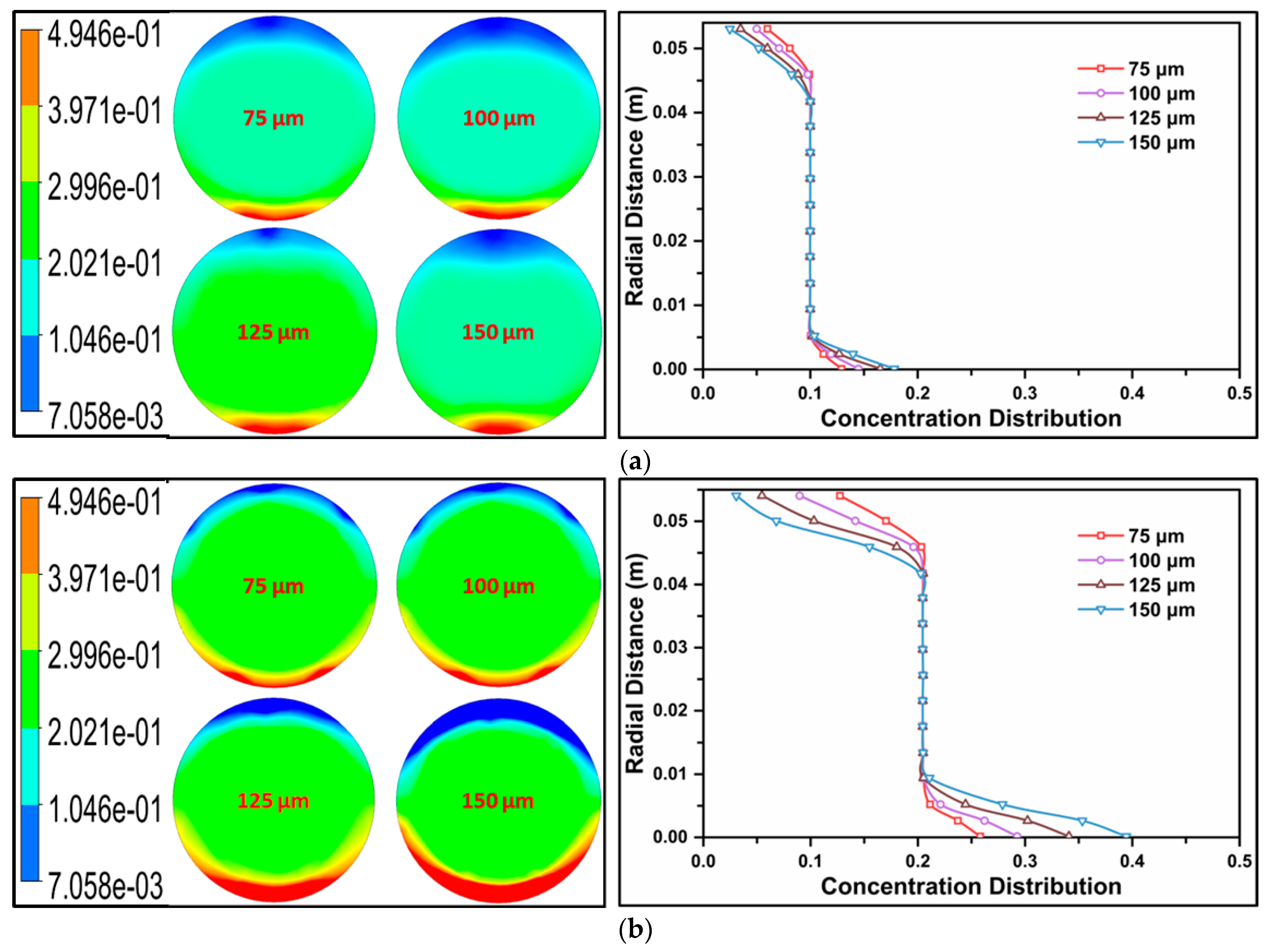
The concentration distribution analysis for glass beads in solid granular flow, characterized by a mean flow velocity (Vm) of 1 and volumetric concentration (Cvf) ranging from 10% to 20%, is presented in Figure 4a,b. The investigation encompasses four distinct glass bead sizes: 75 µm, 100 µm, 125 µm, and 150 µm. The concentration distribution exhibits two primary entities—concentration contours on the left and concentration profiles on the right. Notably, smaller diameter particles (75 µm) display lower intensity in concentration distribution due to reduced turbulence, resulting in minimal deviation. As the particle size increases, concentration intensity rises, leading to a higher concentration profile. This phenomenon aligns with findings by Kaushal et al. [18] for 125 µm particles at varying mean flow velocities (Vm = 1–4 m/s). Furthermore, volumetric concentration significantly influences concentration distribution, with higher concentrations correlating to increased intensity, as depicted in Figure 4b. The contours’ reaction area also intensifies with elevated volumetric concentration.
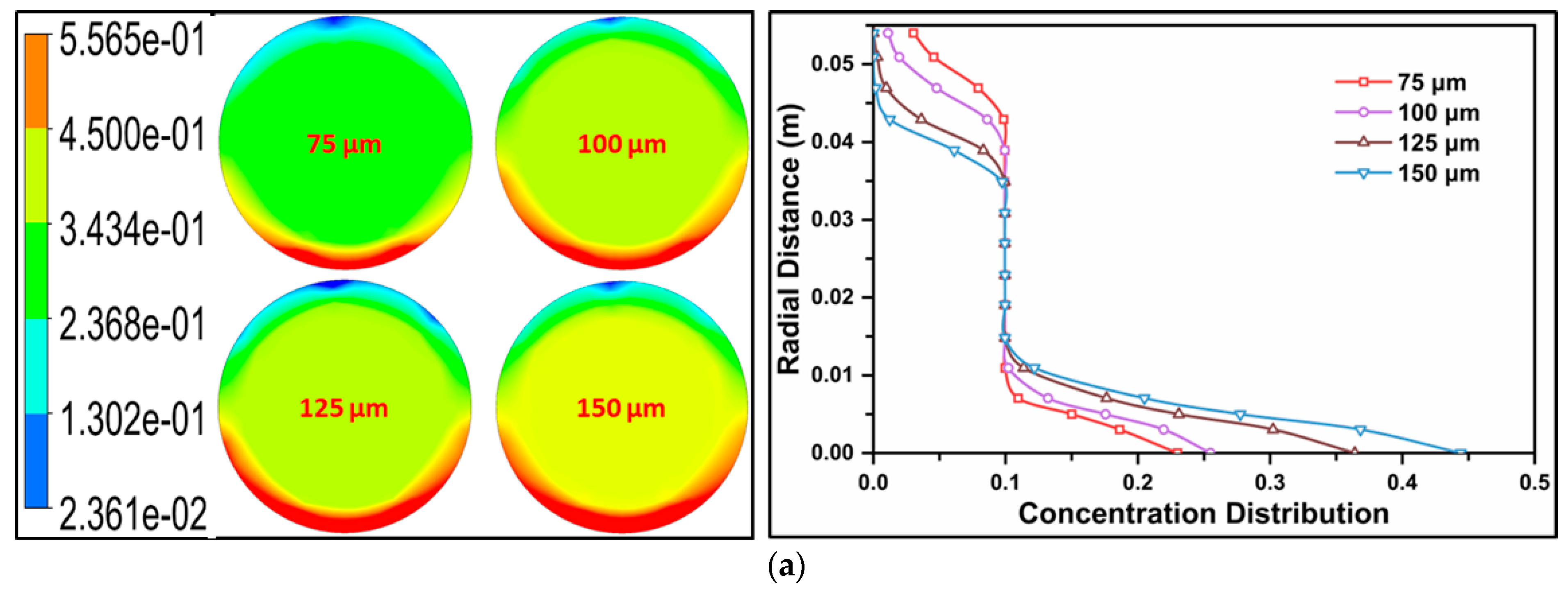
The impact of increased mean flow velocity on concentration distribution is depicted in Figure 5. The figure illustrates that, maintaining a consistent volumetric concentration, concentration distribution becomes more pronounced with higher flow velocity. This phenomenon arises from the accelerated transport of solid granules in high-velocity flows, leading to a broader spread of concentration distribution compared to low-velocity flows. This observation aligns with the findings of Joshi et al. [21], who previously investigated the effect of flow velocity on concentration distribution, noting a substantial widening as velocity increased from Vm = 2 to 5 m/s. Moreover, the granular intensity at the pipe’s bottom augments with elevated mean flow velocity and volumetric concentration.

4.2. Generalized Pressure Gradient Correlation Equation

In a prior study, Gopaliya et al. [14] conducted an investigation to anticipate pressure drop employing computational techniques. They formulated an equation derived from their findings, enabling the prediction of pressure drop without the need for further computational efforts. The author utilized pressure drop data acquired through a second-order parametric model, employing MATLAB regression curve-fitting techniques for analysis. The resulting equation, elucidated below, serves as a tool for predicting the pressure drop based on the established parameters:
Z = 11.23 + 17.14 x 1.071 y + 12.74 x 2 + 5.102 x y + 169.3 y 2 + 10.92 x 3 + 1.052 x 2 y 51.9 x y 2 192.6 y 3 + 3.318 x 4 31.47 x 3 y 65.02 x 2 y 2 + 28.26 x y 3 + 72.14 y 4 5.408 x 5 1.96 x 4 y + 36.67 x 3 y 2 + 29.07 x 2 y 3 5.362 x y 4 8.994 y 5 × 10 7
where
Z = Δ P d ρ S v 2
x = C v f
y = ρ f v D μ f
Here, v is the mean flow velocity, Cvf is volumetric concentration, d refers to granular size, D is the pipe diameter, µf is the viscosity of fluid (0.001003 Pa·s), and ρs and ρf are the density of granular and water, respectively.
The proposed mathematical equation (Equation (23)) appears intricate and presents challenges in terms of comprehension. Notably, Gopaliya et al. [14] did not furnish a comparative analysis between the outcomes derived from their mathematical models and the corresponding experimental or computational results. Furthermore, they omitted addressing limitations inherent in their formulation, including the specific particle size, volumetric concentration, and Reynolds number range for which their equation holds validity. In response to these deficiencies and with the objective of formulating a more versatile prediction equation for pressure drop, this study endeavors to develop a generalized model. The variables in this newly proposed correlation equation are designed to be more inclusive in comparison to the preceding model. The generalized correlation equation is articulated below:
Z = f x , y = A + B × x + C × y + D × x 2 + E × x y + F × y 2 35000 Re 210000 C v f = 10 20   % d 50 = 75 150   μ m
where
Z = Δ P L d ρ v 2
x = C v f
y = Re = ρ f v D μ f
In addition, coefficients as a function (see Equation (27)) of solid granular diameter are expressed as follows:
A = 210.4 d 2 + 0.0312 d + 2 E 06
B = 268 d 2 0.023 d 1 E 05
C = 0.0002 d 2 3 E 07 d + 9 E 12
D = 1412 d 2 0.0321 d + 2 E 05
E = 0.0051 d 2 1 E 06 d + 8 E 11
F = 3 E 09 d 2 + 1 E 12 d 6 E 17
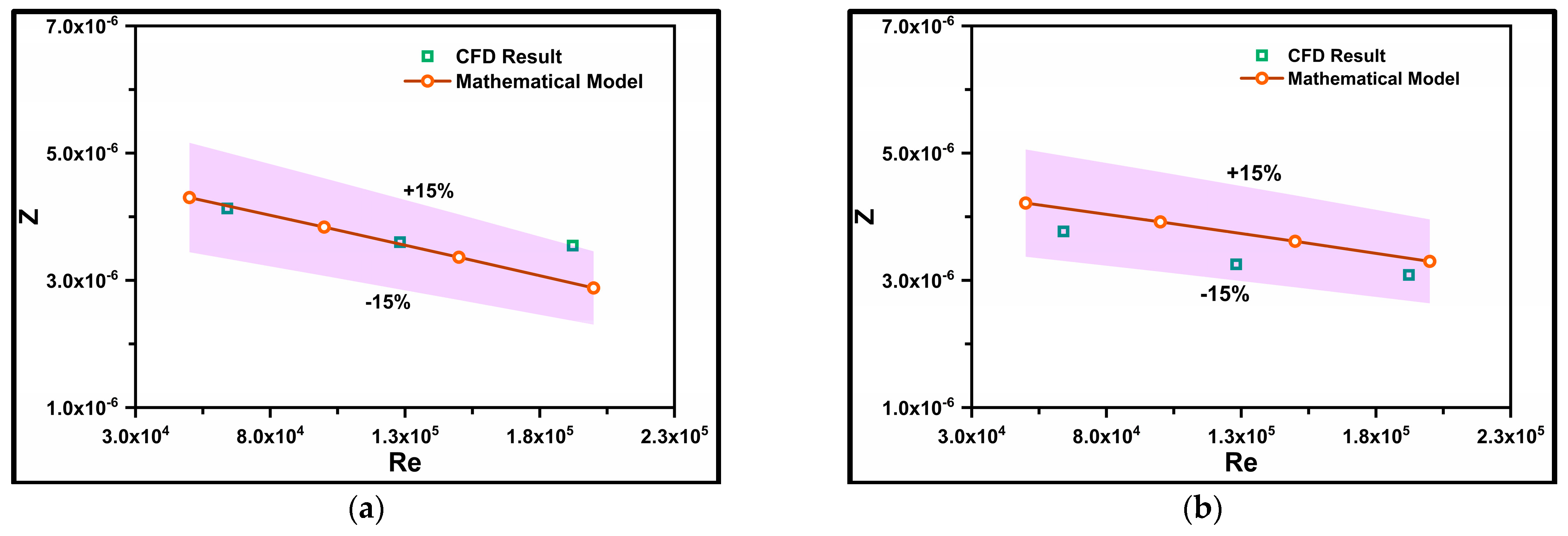
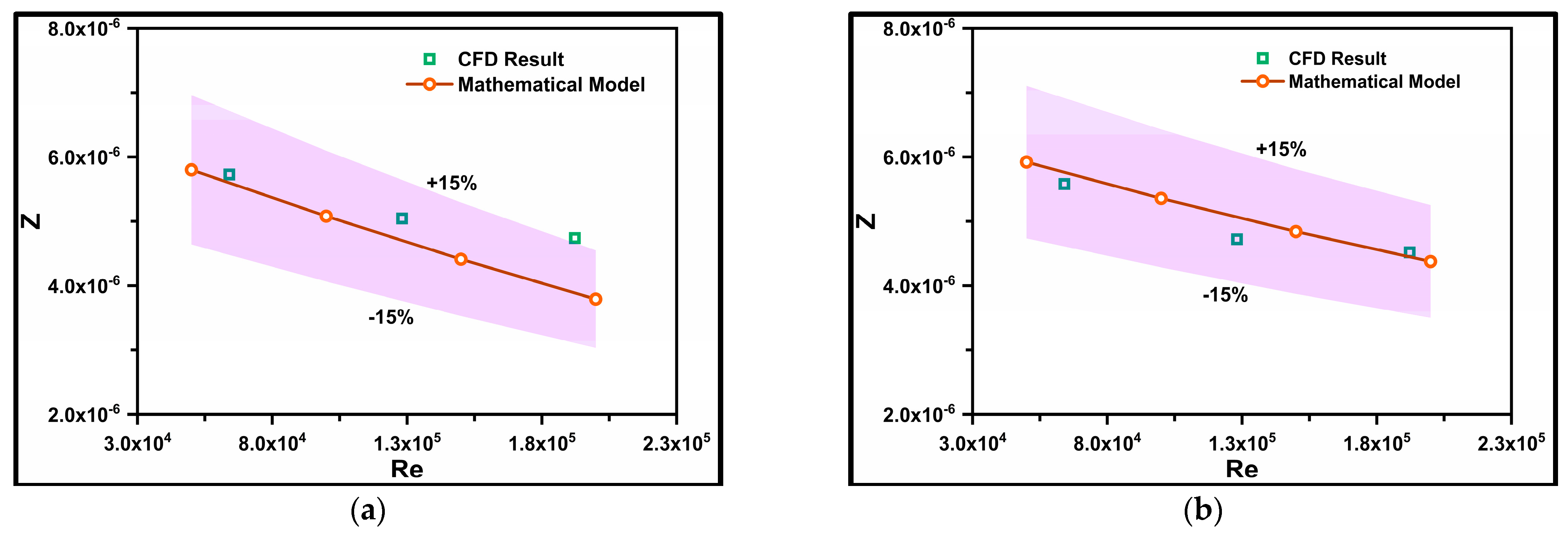
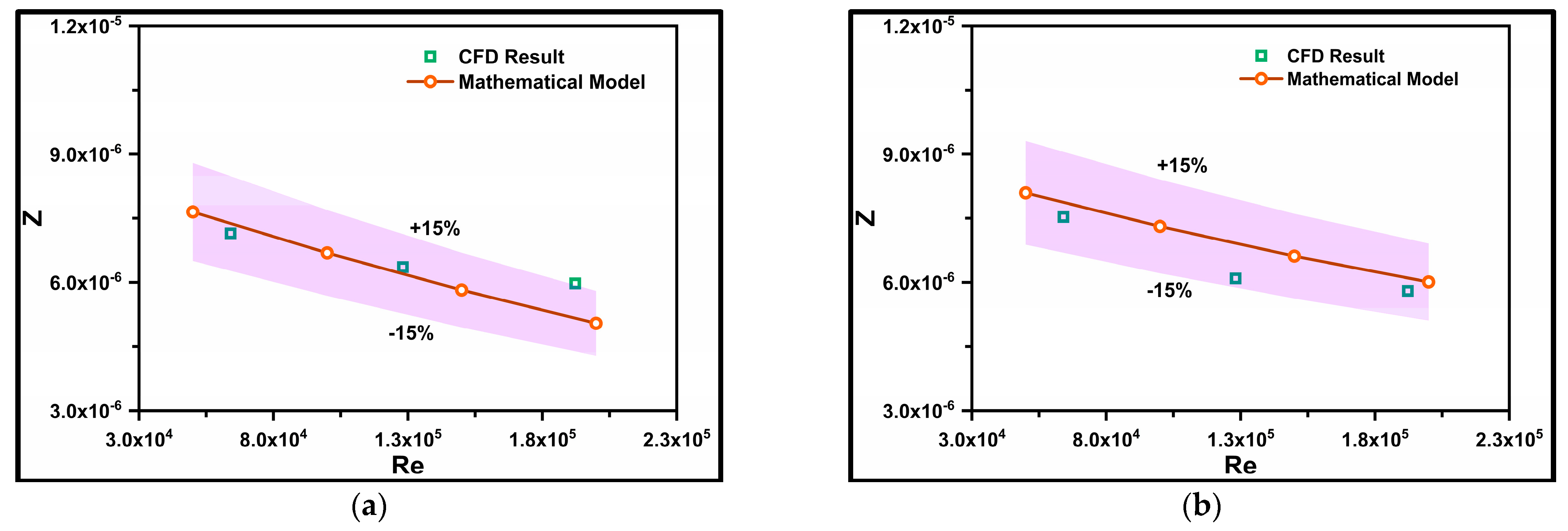
The coefficients in Equation (27) must be determined separately, and the results are then applied to Equation (27) to obtain the resultant pressure drop value. Formulated using the Buckingham Pi theorem, the correlation expresses the terms as [Z = f(x, y)], where Z represents the dependent variable (pressure drop ΔP) and “x” and “y” represent independent variables (solid concentration Cvf and Reynolds number Re). Second-order polynomial correlations for various particle sizes were developed using MATLAB R2022B curve-fitting tool. Figure 6a,b depicts a comparison between the proposed mathematical correlation model developed using MATLAB code and CFD results for particle size d50 = 75 µm at volumetric concentrations Cvf = 10–20%, respectively. The x-axis of the graph represents the Reynolds number (Re), while the y-axis demonstrates the pressure gradient function (Z). These Figure 6 illustrate that the correlation model accurately predicts the variable “Z” for both concentration levels. Additionally, error limits are provided in the graphs to assess whether the CFD results fall within an acceptable range and to quantify the deviation between the two values. An error limit of ±15% of the correlation results is applied, and if the CFD results line falls within the shaded region, then the results are considered acceptable. Similarly, Figure 7, Figure 8, Figure 9 and Figure 10 illustrate the comparison of a pressure gradient (Z) for particle sizes ranging from 100 to 175 µm, respectively. Notably, the magnitude of “Z” increases proportionally with both particle size and efflux concentrations. As particle size increases, the deviation between “Z” values obtained from the mathematical correlation model and the CFD model also increases. Multiple reasons are associated with this behavior of which higher turbulence intensity, and momentum energy are the most significant ones.
The developed correlation model proves accurate in predicting “Z” for smaller solid granules at lower volumetric concentrations. However, as particle size and the number of solid particles in the flow increase, the deviation between the correlation and CFD results surpasses the acceptable limit. Therefore, future work will require further modification, possibly incorporating turbulence variables. The present model accurately predicts the pressure gradient function “Z” and is applicable for particle diameters between 75 and 175 µm, volumetric concentrations of 10–20% (by volume), and Reynolds numbers within the range of 35,000–210,000.

4.3. Pressure Drop Equation

The first direct equation for the pressure drop was published by Turian et al. [9], who investigated the pressure drop equation for the different flow regimes including flow in a stationary bend, heterogeneous, and homogeneous flow. In his work, approximately 2800–2900 data points were considered to obtain a new equation for predicting the pressure drop. The generalized equation for the pressure drop can be written as:
Δ P L = 2 f ρ v 2 D
Here, ΔP/L is pressure gradient, D is the pipe diameter, ρ is density, v refers to velocity, and f is the friction factor.
The limitations of the Turian et al. [9] model include the applicability restricted to the lower density phase, and eliminated by the model proposed by Geldart et al. [13], which includes more than 600 data points to formulate a new equation. The equation is majorly developed for the high-pressure dense phase conveying the coal particle in a small-diameter pipeline. The equation can be presented as follows:
Δ P = 2 G S U + 2 f L ρ g U 2 D + K μ ρ g 0.4 G S D m L U + G S H g V S + n 2 G S U
where
f = 0.07 Re 0.25
K = 106; m = 0.83 for GS/D < 47,000 Kg/(m3·s)
H = Net vertical distance b/w feed and exit portion
n = Number of bends
V S = U 1 0.0638 d p 0.3 ρ p 0.5
Equations (37) and (38) signify initial attempts at formulating advanced equations for predicting pressure drop in slurry flow through pipelines. Despite their novelty, these equations present multiple limitations in accurately forecasting slurry pressure drop. Firstly, the data points derived from these equations deviate by more than 30–40% from the original experimental values, posing challenges in practical applications. Secondly, Equations (37) and (38) do not account for volumetric concentration values, a critical factor in precise pressure drop prediction. The omission of volumetric concentration raises concerns about the models’ accuracy, given the recognized influence of concentration in pressure drop determination [17,20,31,32]. Thirdly, these equations lack specificity regarding the range of conditions under which they validly predict pressure drop. Addressing these limitations necessitates the development of a new, state-of-the-art generalized model offering improved accuracy in pressure drop prediction. The generalized model is presented as follows:
Δ P = 7800 × d 50 × 892.27 C v f 0.6681 × v α       1.55 α 1.95 20000 Re 320000 C v f = 10 50   % d 50 = 75 150   μ m
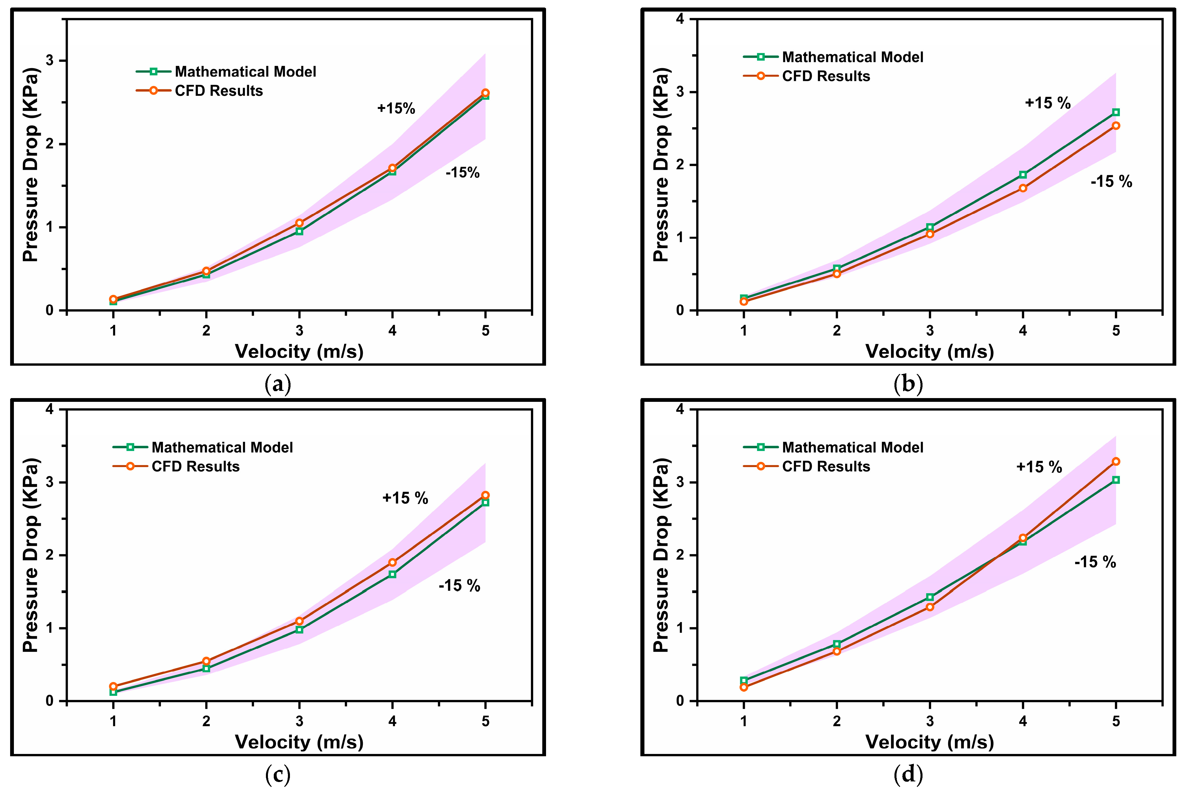
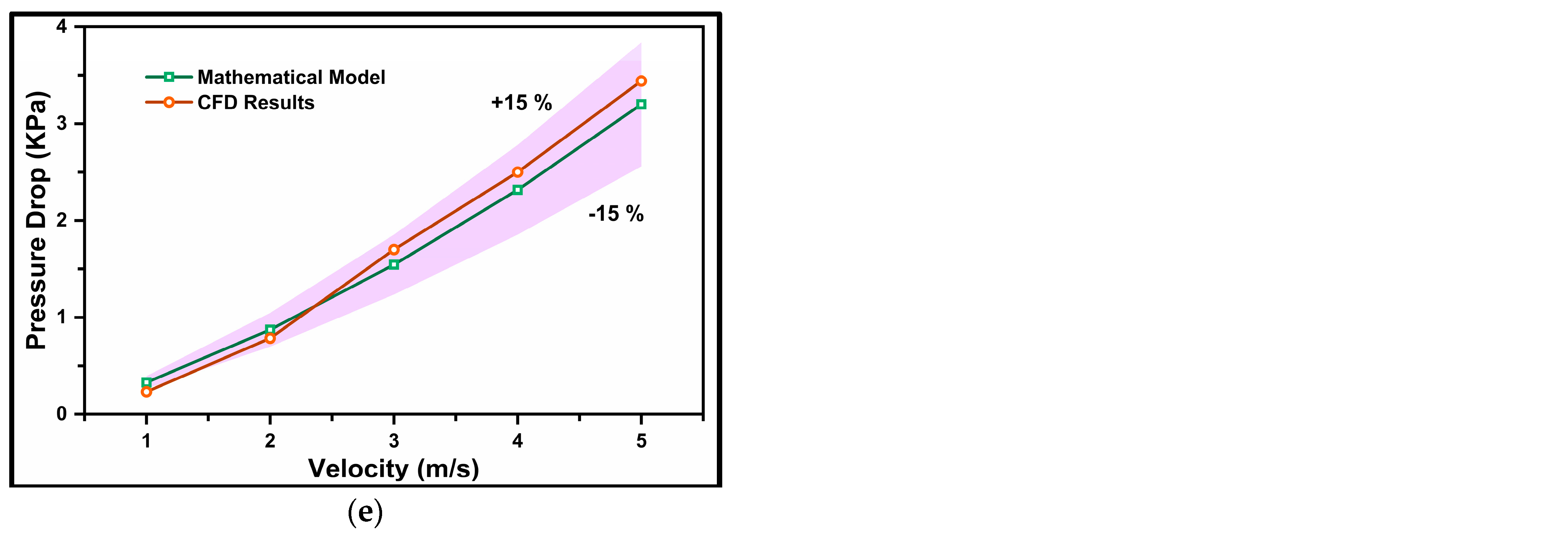
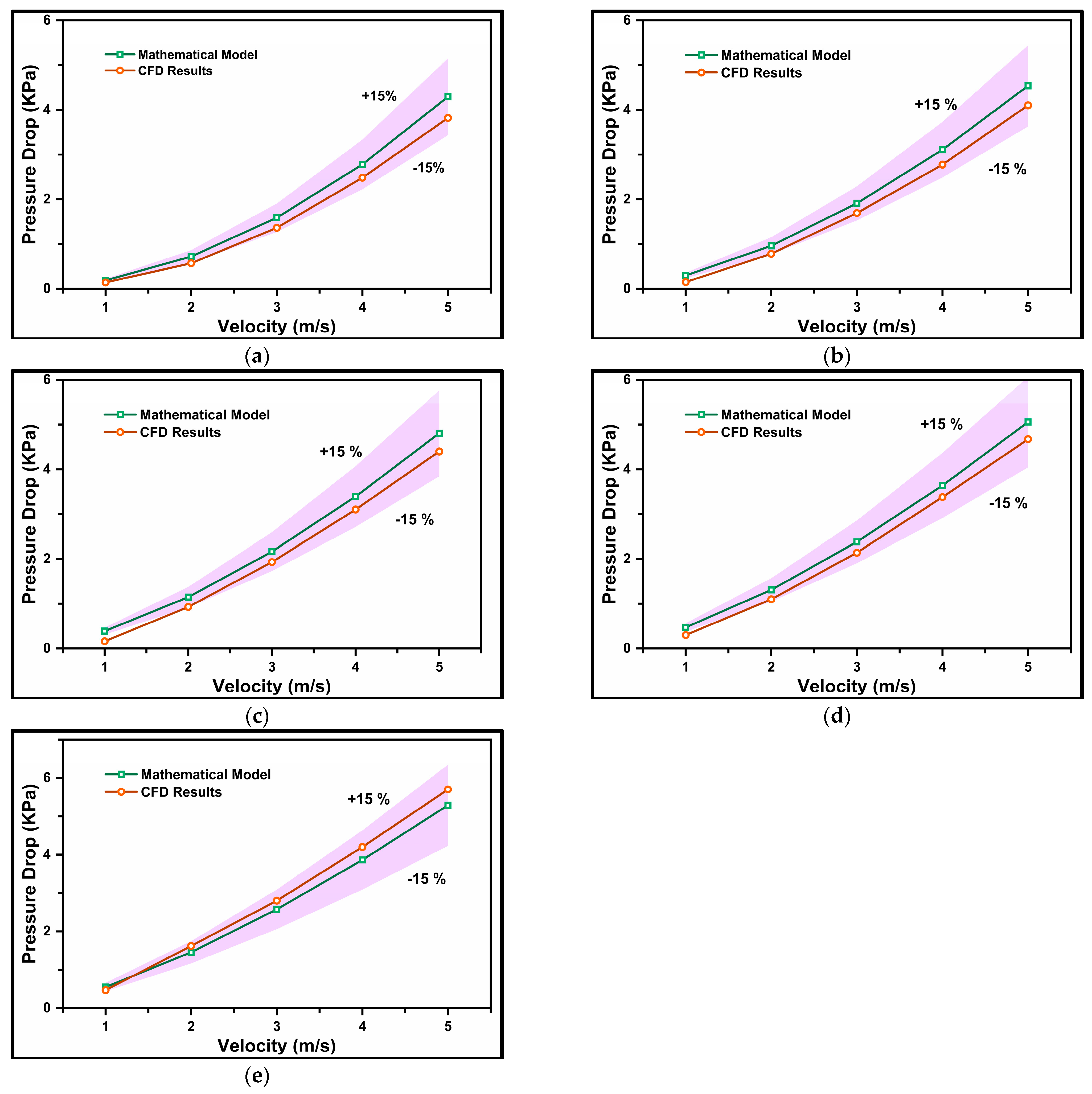
In Equation (41), it can be observed that the equation incorporates all the necessary variables essential for predicting pressure drop. These variables, including particle diameter (d), volumetric concentration (Cvf), flow velocity (v), and power variable (α), are utilized to estimate the pressure drop in the slurry system. Figure 11a–e provides a comparison between the proposed mathematical model and CFD results for a particle size of d50 = 75 µm, flowing at velocities Vm = 1–5 m/s, and volumetric concentrations Cvf = 10–50%, respectively. The x-axis represents flow velocity in m/s, while the y-axis shows the pressure gradient in kPa/m. The Figure 6 demonstrate that the proposed model accurately predicts the pressure drop for every efflux concentration. Similar to the previous section (Section 4.2), an error/deviation limit is provided in this section. The deviation is limited to ±15% of the mathematical model, highlighted in a purple color. If the CFD pressure drop line falls within the shaded region, the results are deemed acceptable.
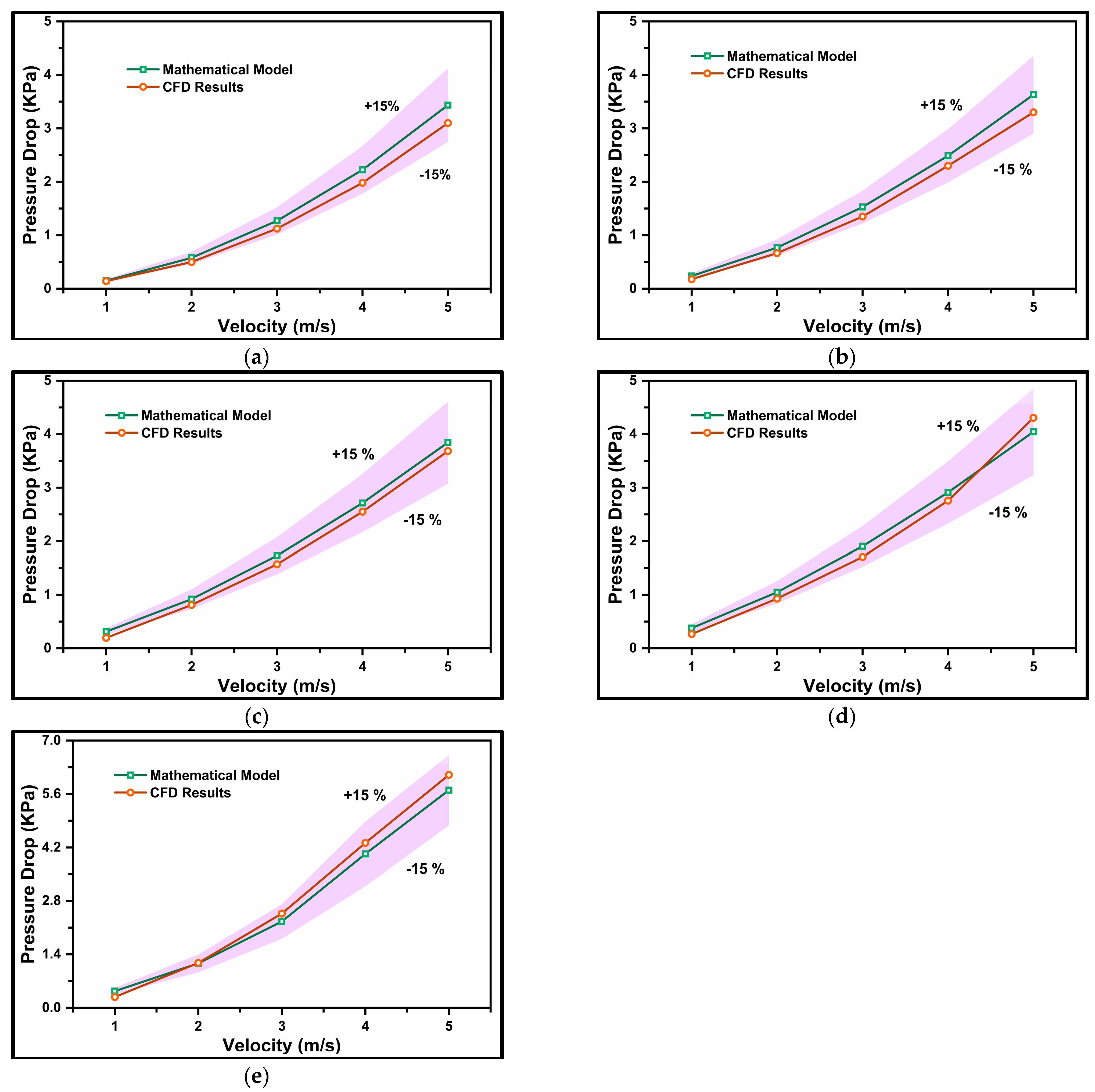
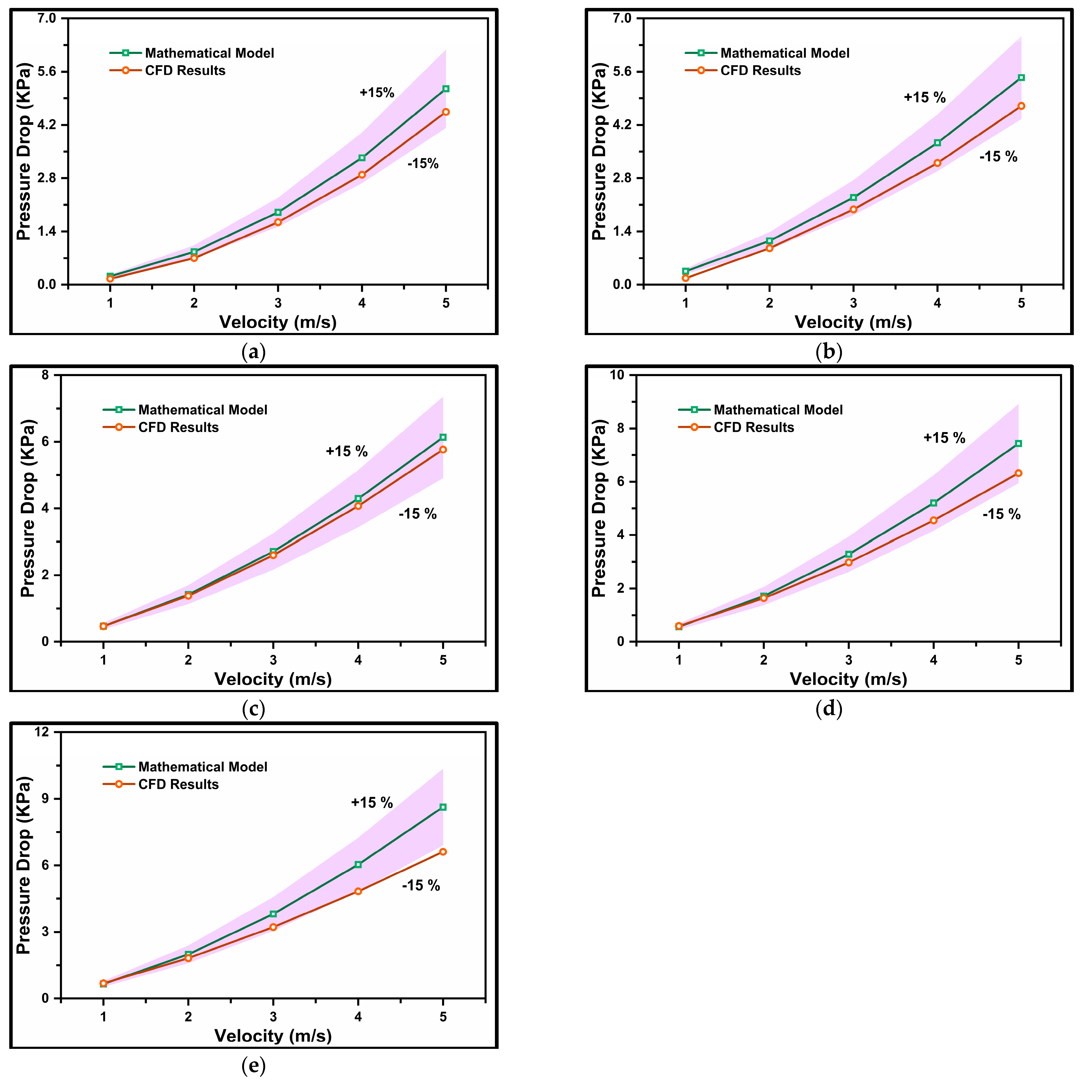
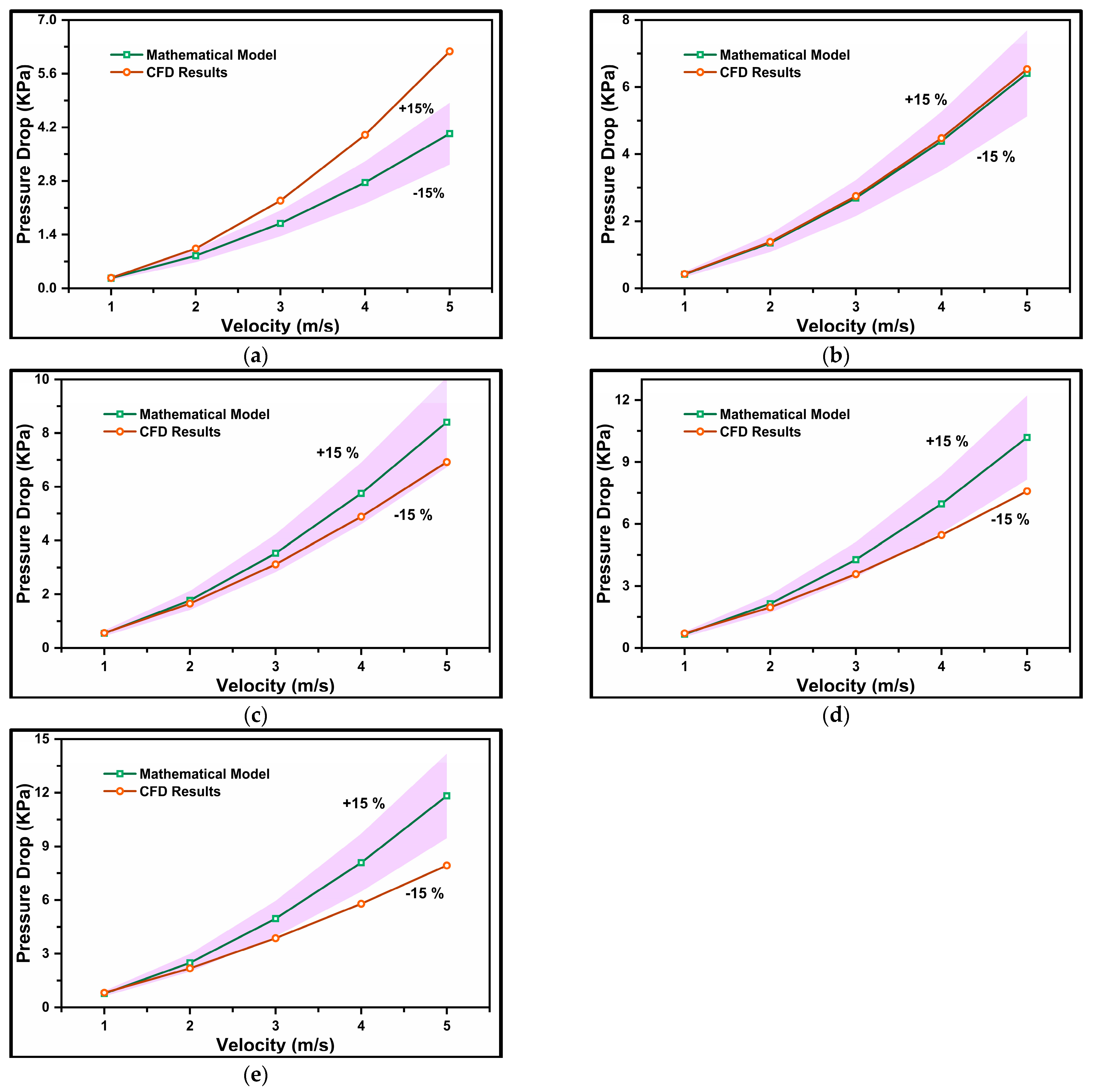
Similarly, Figure 12, Figure 13, Figure 14 and Figure 15 illustrate pressure drop comparisons for particle sizes ranging from 100 to 175 µm. Notably, the pressure drop predictions from the CFD model show increasing deviation with larger solid granule sizes. This deviation occurs because larger solid particles increase turbulence intensity, particle momentum, and kinetic energy within the slurry domain, involving numerous complex variables. Consequently, the deviation becomes more pronounced. For high-intensity transport conditions (higher velocity, Reynolds number, and larger particle size), formulating a generalized model becomes highly complex. This complexity arises from the need to consider multiple field variables to predict pressure drop, and any changes in inlet conditions introduce new variables. Therefore, this equation is not applicable to various inlet and boundary conditions.
As a result, the present model accurately predicts pressure drop values for particle diameters ranging from 75 to 150 µm, volumetric concentrations of 10–50% (by volume), mean flow velocities of 1–5 m/s, and Reynolds numbers up to 320,000. However, when solid granule sizes exceed 150 µm, some CFD results (e.g., Figure 15a,d) deviate from the acceptance limit of ±15% due to a higher number of turbulence variables, making their prediction via the equation highly challenging. Therefore, the equation is valid for particle sizes ranging from 75 to 175 µm (limited cases).

4.4. Mathematical Model Validation

The graphs shown in this section clearly confirm that throughout the specified range of operating parameters, our mathematically suggested model more robustly and reliably predicts the pressure gradient than earlier models found in the literature.
In Figure 16a, data from the literature by Kaushal et al. [18] for glass beads with a size of 125 µm and volumetric concentrations (Cvf) of 10% are projected. The validation process involves comparing the correlation models presented in Section 4.2 (Equation (23)) against the experimental findings. It is evident from the graph that as the Reynolds number increases, the pressure gradient function drops, which is consistent with what is predicted as flow moves from laminar to turbulent regimes. Our suggested model closely matches the experimental data, especially at higher Reynolds numbers, suggesting that it can correctly describe the pressure gradient’s behavior under these circumstances. At lower Reynolds numbers, there is a tiny underestimating of Z; however, this divergence is small and well within acceptable bounds, demonstrating the model’s resilience. The presented graph establishes that the proposed models exhibit good agreement with the experimental data reported by Kaushal et al. [18]. This strong correlation across a wide range of Reynolds numbers suggests that our model offers a more reliable prediction of the pressure gradient function than previously available models.
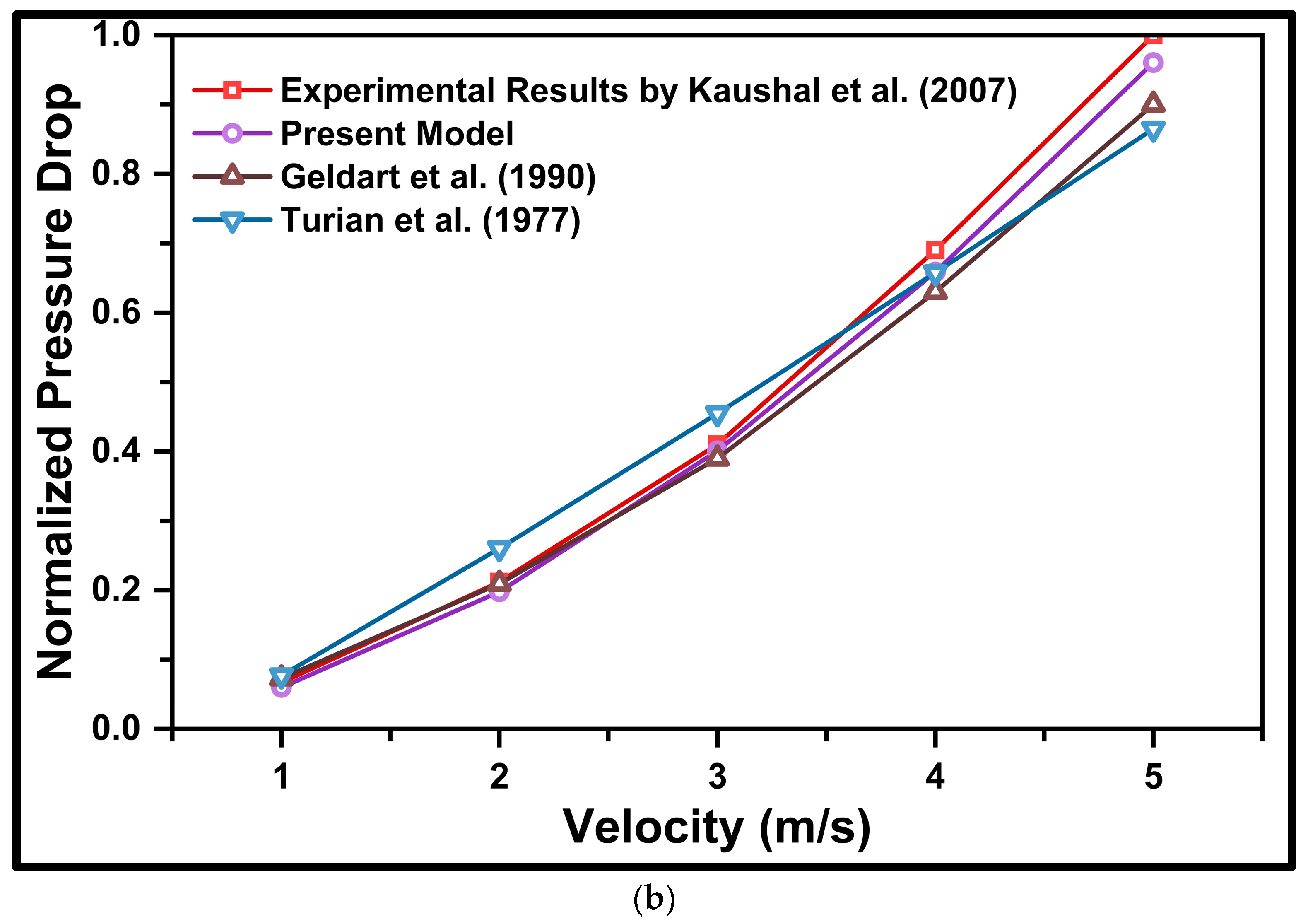
Figure 16b shows the normalized pressure drop as a function of velocity, comparing our model’s predictions (Equation (41)) with experimental data from Kaushal et al. [18], and established models by Turian et al. [9], and Geldart et al. [13]. All the pressure drop results were carried out for glass beads having d50 = 125 µm, flowing at Vm = 1–5 m/s, and Cvf = 20%. The results demonstrate that our model aligns closely with the experimental data and outperforms the other models across the entire velocity range. This superior performance is particularly evident at lower velocities, where the present model’s predictions closely match the experimental results, indicating its enhanced accuracy. Even at higher velocities, where slight deviations are observed, our model maintains a closer match with the experimental data compared to the other models, underscoring its robustness and reliability. It is important to note that our developed model is more robust and accurate in predicting the pressure drop, whereas the models developed by Turian et al. [9], and Geldart et al. [13] failed to accurately predict the pressure drop due to the absence of the volumetric concentration (Cvf) term. Therefore, these models are unable to differentiate between slurries with lean mixtures and those with very rich mixtures. This limitation further highlights the superiority of our model in providing accurate predictions under varying slurry concentrations.

5. Conclusions

The current study conducted a comprehensive three-dimensional computational investigation and developed mathematical equations for predicting the pressure drop in a straight pipe. The computational analysis utilized the Eulerian–Eulerian multiphase approach with the RNG k-ε turbulence model. Two distinct mathematical formulations were proposed based on computational results, leading to the following key conclusions:
  • The mathematical correlation models demonstrated excellent predictive capabilities for pressure drop, validated against experimental data from Kaushal et al. [18]. The concentration distribution obtained through the CFD model was also validated against experimental results for d50 = 125 µm at Vm = 4 m/s and Cvf = 30%.
  • Slurries featuring smaller particle diameters, lower volumetric concentrations, and lower velocities exhibited minimal concentration distribution. Conversely, larger particle diameters, higher flow velocities, and higher volumetric concentrations correlated with increased concentration distribution. Maximum concentration intensity was observed at the bottom of the pipe.
  • A mathematical formulation was introduced using a second-order polynomial correlation equation to predict “Z”, representing the pressure gradient. Developed with MATLAB code, Equation 27 accurately predicted the pressure gradient for particle diameters of d50 = 75–175 µm, volumetric concentrations of Cvf = 10–20%, and Reynolds numbers of 35,000 ≤ Re ≤ 210,000.
  • A novel mathematical equation, dependent on mean flow velocity (v), particle diameter (d), and volumetric concentration (Cvf), was proposed. Pressure drop values obtained from this model were compared with experimental and CFD values. Equation 41 accurately predicted the pressure gradient for particle diameters of d50 = 75–175 µm, volumetric concentrations of Cvf = 10–50%, and Reynolds numbers of 20,000 ≤ Re ≤ 320,000.

Author Contributions

Conceptualization, T.J., O.P. and A.G.; methodology, T.J., O.P., G.K. and A.G.; software, G.K. and T.J.; validation, T.J. and G.K.; formal analysis, T.J., O.P., N.L.O. and A.G.; investigation, T.J., G.K. and A.G.; resources, G.K. and R.K.B.G.; data curation, G.K. and R.K.B.G.; writing—original draft preparation, O.P., G.K. and T.J.; writing—review and editing, R.K.B.G. and G.K.; visualization, T.J.; supervision, G.K. and O.P.; project administration, N.L.O., G.K. and R.K.B.G. All authors have read and agreed to the published version of the manuscript.

Funding

This research received no external funding.

Data Availability Statement

Data will be available on request.

Conflicts of Interest

The authors declare no conflicts of interest.

References

  1. Joshi, T.; Parkash, O.; Krishan, G. Estimation of energy consumption and transportation characteristics for slurry flow through a horizontal straight pipe using computational fluid dynamics. Phys. Fluids 2023, 35, 053303. [Google Scholar] [CrossRef]
  2. Joshi, T.; Parkash, O.; Krishan, G. CFD modeling for slurry flow through a horizontal pipe bend at different Prandtl number. Int. J. Hydrogen Energy 2022, 47, 23731–23750. [Google Scholar] [CrossRef]
  3. Zenz, F.A. Two-Phase Fluid-Solid Flow. Ind. Eng. Chem. 1949, 41, 2801–2806. [Google Scholar] [CrossRef]
  4. O’Brien, M.P. Review of the theory of turbulent flow and its relation to sediment-transportation. Trans. Am. Geophys. Union 1933, 14, 487–491. [Google Scholar] [CrossRef]
  5. Rouse, H. Modern Conceptions of the Mechanics of Fluid Turbulence. Trans. Am. Soc. Civ. Eng. 1937, 102, 463–505. [Google Scholar] [CrossRef]
  6. Fundamentals of Multiphase Flow—Google Books n.d. Available online: https://www.google.co.in/books/edition/Fundamentals_of_Multiphase_Flow/F7hEfx2GUPYC?hl=en&gbpv=1&pg=PR13&printsec=frontcover&bshm=rime/1,rime/1 (accessed on 14 September 2023).
  7. Zandi, I.; Govatos, G. Heterogeneous Flow of Solids in Pipelines. J. Hydraul. Div. 1967, 93, 145–159. [Google Scholar] [CrossRef]
  8. Worster, R.C.; Denny, D.F. Hydraulic Transport of Solid Material in Pipes. Proc. Inst. Mech. Eng. 1955, 169, 563–586. [Google Scholar] [CrossRef]
  9. Turian, R.M.; Yuan, T. Flow of slurries in pipelines. AIChE J. 1977, 23, 232–243. [Google Scholar] [CrossRef]
  10. Newitt, D.M.; Richardson, J.F.; Abbot, M.; Turtle, R.B. Hydraulic conveying of solids in horizontal pipes. Trans. Inst. Chem. Eng. 1955, 33, 93–113. [Google Scholar]
  11. Condolios, E.; Chapus, E.E. Designing Solids Handling Pipelines. Chem. Eng. 1963, 70, 106686455. [Google Scholar]
  12. Bantin, R.A.; Streat, M. Mechanism of Hydraulic Conveying at High Concentration in Vertical and Horizontal Pipes; Transport and Road Research Laboratory (TRRL): Wokingham, UK, 1973. [Google Scholar]
  13. Geldart, D.; Ling, S. Dense phase conveying of fine coal at high total pressures. Powder Technol. 1990, 62, 243–252. [Google Scholar] [CrossRef]
  14. Gopaliya, M.K.; Kaushal, D.R. A Correlation for Pressure Drop Prediction for Solid-Liquid Slurry Flows through Horizontal Pipelines. Multiph. Sci. Technol. 2020, 32, 311–324. [Google Scholar] [CrossRef]
  15. Iwanami, S.; Kato, H.; Yamane, R. Pressure Drop in Hydraulic Conveyor through a Horizontal Straight Pipe. Bull. JSME 1964, 7, 552–558. [Google Scholar] [CrossRef]
  16. Ling, J.; Skudarnov, P.V.; Lin, C.X.; Ebadian, M.V. Numerical investigations of liquid–solid slurry flows in a fully developed turbulent flow region. Int. J. Heat Fluid Flow 2003, 24, 389–398. [Google Scholar] [CrossRef]
  17. Kaushal, D.; Sato, K.; Toyota, T.; Funatsu, K.; Tomita, Y. Effect of particle size distribution on pressure drop and concentration profile in pipeline flow of highly concentrated slurry. Int. J. Multiph. Flow 2005, 31, 809–823. [Google Scholar] [CrossRef]
  18. Kaushal, D.R.; Tomita, Y. Experimental investigation for near-wall lift of coarser particles in slurry pipeline using γ-ray densitometer. Powder Technol. 2007, 172, 177–187. [Google Scholar] [CrossRef]
  19. Kaushal, D.; Thinglas, T.; Tomita, Y.; Kuchii, S.; Tsukamoto, H. CFD modeling for pipeline flow of fine particles at high concentration. Int. J. Multiph. Flow 2012, 43, 85–100. [Google Scholar] [CrossRef]
  20. Joshi, T.; Parkash, O.; Krishan, G. Numerical Investigation of Slurry Pressure Drop at Different Pipe Roughness in a Straight Pipe Using CFD. Arab. J. Sci. Eng. 2022, 47, 15391–15414. [Google Scholar] [CrossRef]
  21. Joshi, T.; Parkash, O.; Murthy, A.A.; Krishan, G. Numerical investigation of Bi-model slurry transportation in a straight pipe. Results Eng. 2023, 17, 100858. [Google Scholar] [CrossRef]
  22. Enwald, H.; Peirano, E.; Almstedt, A.-E. Eulerian two-phase flow theory applied to fluidization. Int. J. Multiph. Flow 1996, 22, 21–66. [Google Scholar] [CrossRef]
  23. Shi, X.; Zhang, P. Conjugated heat and mass transfer during flow melting of a phase change material slurry in pipes. Energy 2016, 99, 58–68. [Google Scholar] [CrossRef]
  24. Nayak, B.B.; Chatterjee, D. Numerical investigation of convective heat transfer in pipeline flow of multi-sized mono dispersed fly ash-water slurry. Int. J. Heat Mass Transf. 2017, 108, 1802–1818. [Google Scholar] [CrossRef]
  25. Lun, C.K.K.; Savage, S.B.; Jeffrey, D.J.; Chepurniy, N. Kinetic theories for granular flow: Inelastic particles in Couette flow and slightly inelastic particles in a general flowfield. J. Fluid Mech. 1984, 140, 223–256. [Google Scholar] [CrossRef]
  26. Gidaspow, D.; Bezburuah, R.; Ding, J. Hydrodynamics of Circulating Fluidized Beds: Kinetic Theory Approach; Illinois Inst. of Tech., Dept. of Chemical Engineering: Chicago, IL, USA, 1991. [Google Scholar]
  27. Schaeffer, D.G. Instability in the evolution equations describing incompressible granular flow. J. Differ. Equ. 1987, 66, 19–50. [Google Scholar] [CrossRef]
  28. Syamlal, M.; Rogers, W.; O’Brien, T.J. MFIX Documentation Theory Guide; USDOE Morgantown Energy Technology Center: Morgantown, WV, USA, 1993. [Google Scholar] [CrossRef]
  29. Kaushal, D.; Kumar, A.; Tomita, Y.; Kuchii, S.; Tsukamoto, H. Flow of mono-dispersed particles through horizontal bend. Int. J. Multiph. Flow 2013, 52, 71–91. [Google Scholar] [CrossRef]
  30. Garside, J.; Al-Dibouni, M.R. Velocity-Voidage Relationships for Fluidization and Sedimentation in Solid-Liquid Systems; ACS Publications: Washington, DC, USA, 2002. [Google Scholar] [CrossRef]
  31. Lai, Z.; Zhao, J.; Zhao, S.; Huang, L. Signed distance field enhanced fully resolved CFD-DEM for simulation of granular flows involving multiphase fluids and irregularly shaped particles. Comput. Methods Appl. Mech. Eng. 2023, 414, 116195. [Google Scholar] [CrossRef]
  32. Beccati, N.; Ferrari, C.; Parma, M.; Semprini, M. Eulerian multi-phase CFD model for predicting the performance of a centrifugal dredge pump. Int. J. Comput. Methods Exp. Meas. 2019, 7, 316–326. [Google Scholar] [CrossRef]
  33. Joshi, T.; Parkash, O.; Krishan, G. Slurry flow characteristics through a horizontal pipeline at different Prandtl number. Powder Technol. 2022, 413, 118008. [Google Scholar] [CrossRef]
  34. Joshi, T.; Parkash, O.; Krishan, G.; Murthy, A.A. Numerical investigation of Bi-model slurry transportation through horizontal pipe bend. Powder Technol. 2023, 418, 118284. [Google Scholar] [CrossRef]
  35. Joshi, T.; Parkash, O.; Gallegos, R.K.B.; Krishan, G. Computational investigation of transportation and thermal characteristics in a bi-modal slurry flow through a horizontally placed pipe bend. Powder Technol. 2024, 442, 119879. [Google Scholar] [CrossRef]
  36. Joshi, T.; Parkash, O.; Gallegos, R.K.B.; Krishan, G. Parametric investigation of slurry transport: Computational insight into the impact of particle composition and Prandtl numbers. Phys. Fluids 2024, 36, 023308. [Google Scholar] [CrossRef]
  37. Joshi, T.; Sharma, R.; Mittal, V.K.; Gupta, V.; Krishan, G. Dynamic Analysis of Hip Prosthesis Using Different Biocompatible Alloys. ASME Open J. Eng. 2022, 1, 011001. [Google Scholar] [CrossRef]
  38. Joshi, T.; Sharma, R.; Mittal, V.K.; Gupta, V.; Krishan, G. Dynamic Fatigue Behavior of Hip Joint under Patient Specific Loadings. Int. J. Automot. Mech. Eng. 2022, 19, 10014–10027. [Google Scholar] [CrossRef]
Figure 1. Schematic diagram of computational flow domain.
Mathematics 12 02879 g001
Figure 2. (a) Meshed model; (b) velocity distribution mesh independence test for d50 = 125 µm, Vm = 2 m/s, and Cvf = 20%.
Mathematics 12 02879 g002
Figure 3. Concentration distribution validation for d50 = 125 µm at Vm = 4 m/s, and Cvf = 30%. Kaushal et al. [18].
Mathematics 12 02879 g003
Figure 4. Concentration distribution for d50 = 75–150 µm particle at Vm = 1 m/s; (a) Cvf = 10%; (b) Cvf = 20%.
Mathematics 12 02879 g004
Figure 5. Concentration distribution for d50 = 75–150 µm particle at Vm = 2 m/s; (a) Cvf = 10%; (b) Cvf = 20%.
Mathematics 12 02879 g005aMathematics 12 02879 g005b
Figure 6. Comparison between proposed mathematical correlation model and CFD model for particle size d50 = 75 µm, and efflux concentration; (a) Cvf = 10%; (b) Cvf = 20%.
Mathematics 12 02879 g006
Figure 7. Comparison between proposed mathematical correlation model and CFD model for particle size d50 = 100 µm, and efflux concentration; (a) Cvf = 10%; (b) Cvf = 20%.
Mathematics 12 02879 g007
Figure 8. Comparison between proposed mathematical correlation model and CFD model for particle size d50 = 125 µm, and efflux concentration; (a) Cvf = 10%; (b) Cvf = 20%.
Mathematics 12 02879 g008
Figure 9. Comparison between proposed mathematical correlation model and CFD model for particle size d50 = 150 µm, and efflux concentration; (a) Cvf = 10%; (b) Cvf = 20%.
Mathematics 12 02879 g009
Figure 10. Comparison between proposed mathematical correlation model and CFD model for particle size d50 = 175 µm, and efflux concentration; (a) Cvf = 10%; (b) Cvf = 20%.
Mathematics 12 02879 g010
Figure 11. The pressure gradient comparison between a proposed mathematical model and CFD model for particle size d50 = 75 µm and efflux concentration; (a) Cvf = 10%; (b) Cvf = 20%; (c) Cvf = 30%; (d) Cvf = 40%; (e) Cvf = 50%.
Mathematics 12 02879 g011aMathematics 12 02879 g011b
Figure 12. The pressure gradient comparison between a proposed mathematical model and CFD model for particle size d50 = 100 µm and efflux concentration; (a) Cvf = 10%; (b) Cvf = 20%; (c) Cvf = 30%; (d) Cvf = 40%; (e) Cvf = 50%.
Mathematics 12 02879 g012
Figure 13. The pressure gradient comparison between a proposed mathematical model and CFD model for particle size d50 = 125 µm and efflux concentration; (a) Cvf = 10%; (b) Cvf = 20%; (c) Cvf = 30%; (d) Cvf = 40%; (e) Cvf = 50%.
Mathematics 12 02879 g013
Figure 14. The pressure gradient comparison between a proposed mathematical model and CFD model for particle size d50 = 150 µm and efflux concentration; (a) Cvf = 10%; (b) Cvf = 20%; (c) Cvf = 30%; (d) Cvf = 40%; (e) Cvf = 50%.
Mathematics 12 02879 g014
Figure 15. The pressure gradient comparison between a proposed mathematical model and CFD model for particle size d50 = 175 µm and efflux concentration; (a) Cvf = 10%; (b) Cvf = 20%; (c) Cvf = 30%; (d) Cvf = 40%; (e) Cvf = 50%.
Mathematics 12 02879 g015
Figure 16. (a) Comparative validation between the experimental and correlation model for d50 = 125 µm and Cvf = 10%; (b) comparison between the experimental results of the Kaushal et al. [18] developed model, the model developed by Turian et al. [9], and Geldart et al. [13].
Mathematics 12 02879 g016aMathematics 12 02879 g016b
Table 1. CFD setup and solution strategy.
Input ParameterMagnitude
Solver typedPressure based
CFD modelEulerian–Eulerian multiphase model
Turbulence modelRNG k-ε model
TimeSteady-state
Phases Two phases (glass beads + water)
Pipe wall No slip condition
Wall behaviorNo slip model
Convergence criteria10−4
Fluid propertyConstant at 27 °C
Solution methodsDiffusive second order upwind SIMPLE scheme is applied for pressure, volume fraction, turbulent kinetic energy, and dissipation rate
Disclaimer/Publisher’s Note: The statements, opinions and data contained in all publications are solely those of the individual author(s) and contributor(s) and not of MDPI and/or the editor(s). MDPI and/or the editor(s) disclaim responsibility for any injury to people or property resulting from any ideas, methods, instructions or products referred to in the content.