1. Introduction
Form factors are paramount physical manifolds which facilitate intervention in all processes that involve radiative heat transfer. As this ever-present manifestation of heat transfer takes place without any kind of contact between the intervening bodies, the forms and spatial relationships of the mentioned elements are pivotal to define to what extent energy is emitted and received [
1]. In other words, the distribution and appearance of radiation fields is a function of the volumetric or three-dimensional disposition of the bodies that exchange radiation [
2]. It is easy to outline the process for differential elements but if the need arises to extend the issue to well-defined geometries, like the circle, the spheroid or the triangle [
3,
4], a great number of drawbacks and shortcomings appear, often provoking us to fall short of reliable or robust solutions to the problem.
In addition, circles, semicircles and its derived circular sectors are ever-present both in human creations and in the natural realm. However, mathematically speaking they have produced a certain level of enigma or even mysticism since ancient times for being such a perfect shape that enclosed the irrational value which we now call π. Such a figure was relatively unknown until the seventeenth century; polymaths such as Guarini even equated it, after so many centuries, to the Archimedes fraction of 22/7 or sometimes 25/8 which, giving a value of 3.125, introduces a considerable degree of error [
3]. Eventually, Lambert had to demonstrate well after the eighteenth century that π was in fact an irrational number. In recent years, the author has worked with sections of spheres and other curved bodies as related to radiative heat transfer, which were applied to the finding of form factors pertaining to such special geometries, to the point of defining new postulates [
4]. The main theorems thus far enunciated refer to the radiative exchange between circles and half disks, but recently the possibility to treat circular sectors has arrived, thanks to the research already conducted. In it, by virtue of Cabeza-Lainez’s first postulate [
5,
6], we are able to determine the form factor of any spherical segment over itself, discarding in this way the former uncertainties that appeared when dealing with the inner side of spherical surfaces. As is known, to find the exact expression of the configuration factor by integration alone is mostly a tedious task and the results are not readily available as it has frequently been proved.
Considering the problem from the mathematical point of view, to solve the integral equations that characterize the same, it is mandatory to introduce two rounds of double integrals, very different in nature, which become more complex as we progress with every primitive found [
4]. Conventional calculus is, so to speak, put at a stake here, but the approximate solutions attempted until now fall short of the mark and do not provide a satisfactory output [
5]. Therefore, we need to overcome this problem to avoid increasing errors that threaten the feasibility of the whole process.
In the abovementioned problem of the circular sectors, the author expended great effort to integrate and validate [
6] the first two steps of the basic formulation for radiant exchange. Subsequently, the novelty of the procedure lay in introducing a finite differences approximation for the third and fourth integrals which still remained unsolved. This possibility had not been envisaged by former research on integral equations. This sole output provides us with an ample variety of scenarios previously unforeseen. As a consequence, we are able to analyze with more precision but free-handedly the spatial transference of radiant heat for figures composed of circular sectors such as spherical sectors, like quarters or octaves of spheres. Many architectural, industrial or aircraft modules and objects fall into this category. We already know that spherical shapes cannot be discretized with any accuracy as there are no spherical tiles of the same size. Thus, finite elements or discretization are insufficient because generally speaking there is hardly an adequate discretization of curved bodies as circles or spheres, even in some cases, we can find inexact procedures with triangular tiles. Stochastic and random methods are often as cumbersome as they are inaccurate [
6,
7].
Moreover, the author proposes a novel methodology based on employing some specific constants, silent variables in truth, subsequently turned into variables, to perform the early parts of the fourfold integral and give a result that is completely exact. Previously, only the rectangle and the complete circle had been resolved by total fourfold integration and the author has collaborated to clarify this especially for the case of cuboids [
8]. Still, it remains surprising that comparatively simple shapes like the semicircle or the derived sector could not be added to the list of exact solutions, although we can assume that mathematical constraints made it difficult to surmount [
9].
In the manner that we have proposed above, the last phase of integration is prepared to be completed by numerical methods which we will explain in more detail in the corresponding chapter [
10]. We need to consider that in the first stage only the more feasible configuration factor (a double integral) is considered instead of addressing the form factor (fourfold integral) in a direct fashion [
8]. A significant part of the hindrance found resides in the complexity of spatial bodies that often appear in natural or man-made objects in which the occurrence of radiation is an important phenomenon [
11,
12].
Until now, diverse approaches to these matters have been attempted without success. The circle and circular sectors and segments are generally speaking indivisible into simpler shapes [
13]. The exact solving of the forms that appear in the thus-defined problem might be deemed an important finding and a relevant advance by its own merits, adding to a number of postulates on thermal radiation proposed thus far [
14].
Thus, by developing this manuscript, we hope to overcome with our finding a persistent extent of error. In this situation, we are able to reduce a considerable amount of constraints in the progress of thermal radiation science due to the advances hereby presented. As the new formulations attained can be adapted for algorithms, they will be integrated into simulation procedures with significant avail. In fact, the formulations in algebraic terms are incorporated into the software which the author has developed.
Our achievement can be considered timely in the effort invested to square the elements of mathematics for radiative transfer. Important sequels are already being derived for radiation on the arched entrance to tunnels, aircraft design, low-energy building construction and also lighting and HVAC industries to cite just a few. In the ensuing chapters, we expect to develop in more detail how the whole process has been completed.
2. Materials and Methods: General Expression of Reciprocity in Radiative Exchanges
As has been enunciated several times since the last quarter of the 18th century [
15], we will begin with the canonical expression that regulates the emission and reception of radiative energy between two non-black bodies of any spatial configuration and regardless of their respective positions as shown in
Figure 1. The equation is composed mainly of directional cosines, distances and areas under the following form (Equation (1)):
Equation (1) is often termed the reciprocity principle, the first to propose it was Johann H. Lambert [
16,
17,
18] around 1760. It describes the respective quantity of radiative energy by unit area that will strike any of the two surfaces involved, that is, E
1 and E
2. The corresponding incident angles
θ1 and
θ2 which are shown in the figure stand for the inclination to the normal of the distance line that joins two arbitrary points pertaining to each surface called r
12, both in the equation and in the figure [
19].
In order to solve Equation (1), which allows for finding the amount of a form factor that encompasses the two sources, we need to work out four ascending steps of integration, as explicated in Equation (2) [
20].
Nonetheless, in this manuscript we focus on the first and second steps (Equation (3)), which are more accessible, leaving a sort of envoy for the next step which adopts the form of a constant (
x0) which turns into a variable in the subsequent phases [
21]; that is, it becomes active for the last two stages of integration.
We propose that the last two operations can be executed using a numerical method that extends the former findings to the surface of emission as a sort of mean or average. In this way, we attain the desired figure of the form factor attributed to the two surface sources considered with considerable accuracy [
22]. Afterwards, we show how to apply the thus-found form factors for several three-dimensional configurations that come up in parts of radiation-emitting or -receiving devices and in the openings of buildings [
23,
24].
For other different positions of the surface sources, an exact solution has not been achieved yet [
5], nor for irregular fragments of circular sectors, rectangles and circles or even for the familiar form of the sphere [
25,
26].
Partially conceived methods to address the preliminary integrals have been presented occasionally [
27]. They tend to show the exchanges between the circle and a single point of the receiving surface, and sometimes they adopt the form of blurry tables, with confusing entries [
28,
29]. Instead, we will elaborate the complete formulation in standard mathematical language.
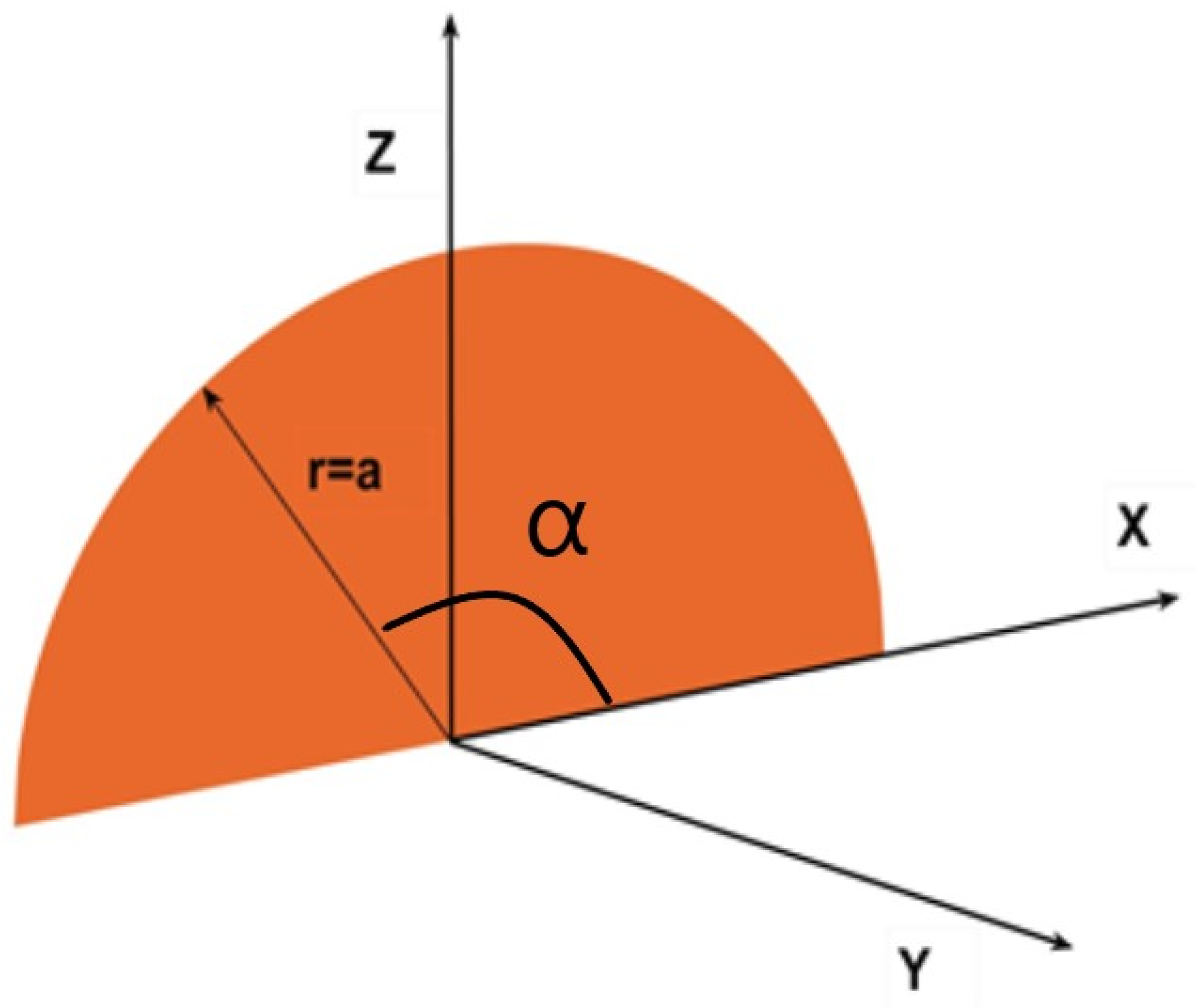
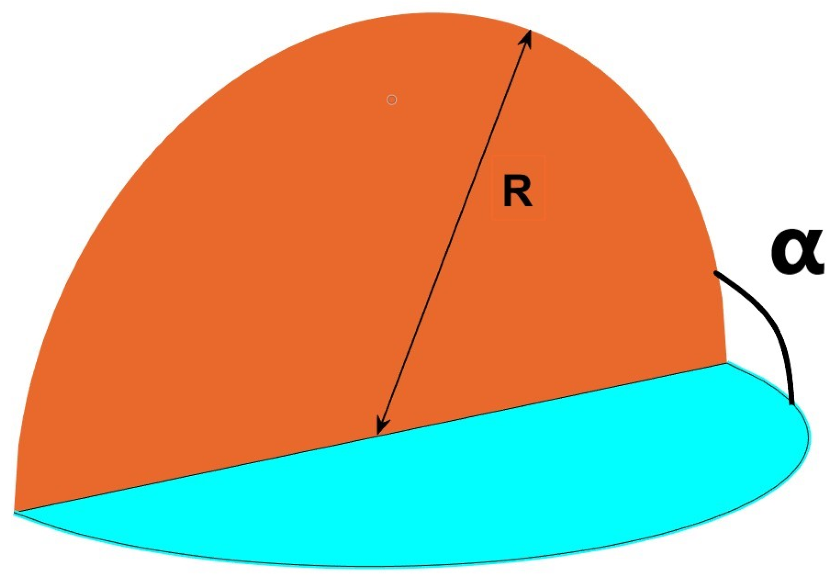
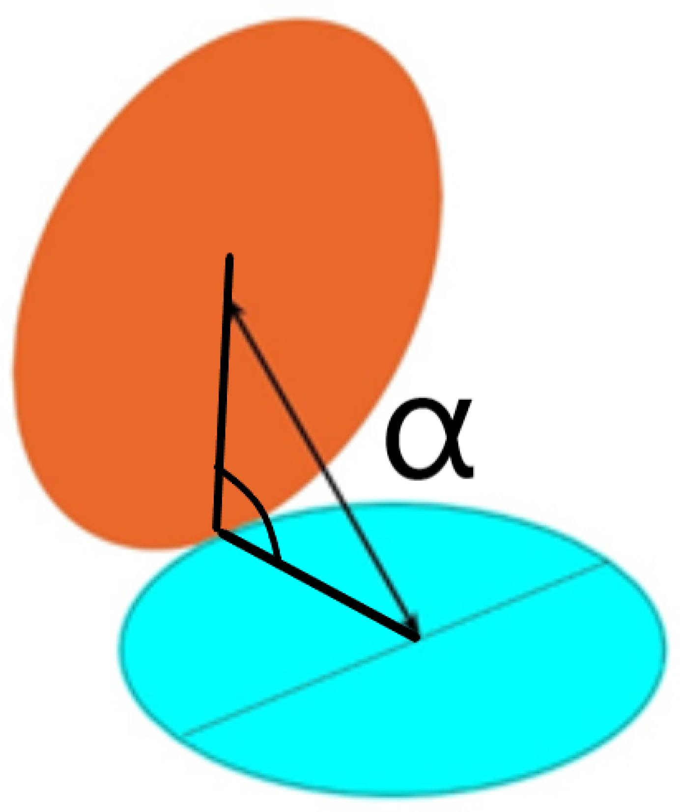
In order to develop our method, we start for simplicity with a semicircle of radius a, placed at the intersection of the main axes X, Y and Z (
Figure 2).
Under this disposition, the coordinate Z axis is vertical and X is horizontal and perpendicular; the Y axis is perpendicular to the semicircle; and the radius of the circular sector turns, in Z, equal to rsinα, and in X, to rcosα as in
Figure 2.
Although it will be demonstrated in the
Appendix A and
Appendix B that the integration could be easily performed in Cartesian coordinates by bringing in the expression of the semicircle, we work in this case in polar coordinates to better explain the relevance of changing the angle α [
30].
The axis Y in the graph represents the free coordinate perpendicular to X.
Introducing the variable
x, limited at first to the semicircle but extended freely in the second part of the process, the distance vector (Equation (4)) from one receiving point pertaining to the semicircle to another emitting point moving freely over the plane XY, presented as
r12 in Equation (2) above, is given in Cartesian coordinates:
The respective cosines
β and
γ, to the normal from Equation (1)–(3), are accordingly
y/
r12 and
z/
r12;
z in this case is equal to
rsinα, as mentioned.
The integral to solve derived from Equation (3) then results in (Equation (5)):
We need to solve the root equation for a generality of types of circular sectors and segments in diverse positions [
31]. To avoid controversial points, we will give the expression for the second step of the configuration factor; that is, we will solve the double integral in the first place, which give the form factor on a point grid on the surface of a rectangular emitter. When this is achieved, we use a different property demonstrated by the author [
32], by virtue of which the full form factor equates to the mean of the point grid over the emitting surface. Utilizing the tools of numerical methods, a planar grid can have any form, rectangular, elliptic or circular, since the average is limited to the points inside the boundary of the shape selected. In a not-dissimilar procedure, we can find the total form factors for volumes composed of circular segments, for instance the space determined by an octave of a sphere. Internal reflections inside the volumes created (three sides are quarters of circles forming a trihedron and the covering surface is an eighth of a sphere) can be determined by special sets of four equations taking into account that one of the surface sources is not planar: see
Appendix B [
33].
By combining the circular sectors, with triangles, rectangles or ellipses we can attain a wider range of forms that were previously unimaginable and not suitable for calculation, which is why the novel procedure that we propose will provide a significant contribution [
34].
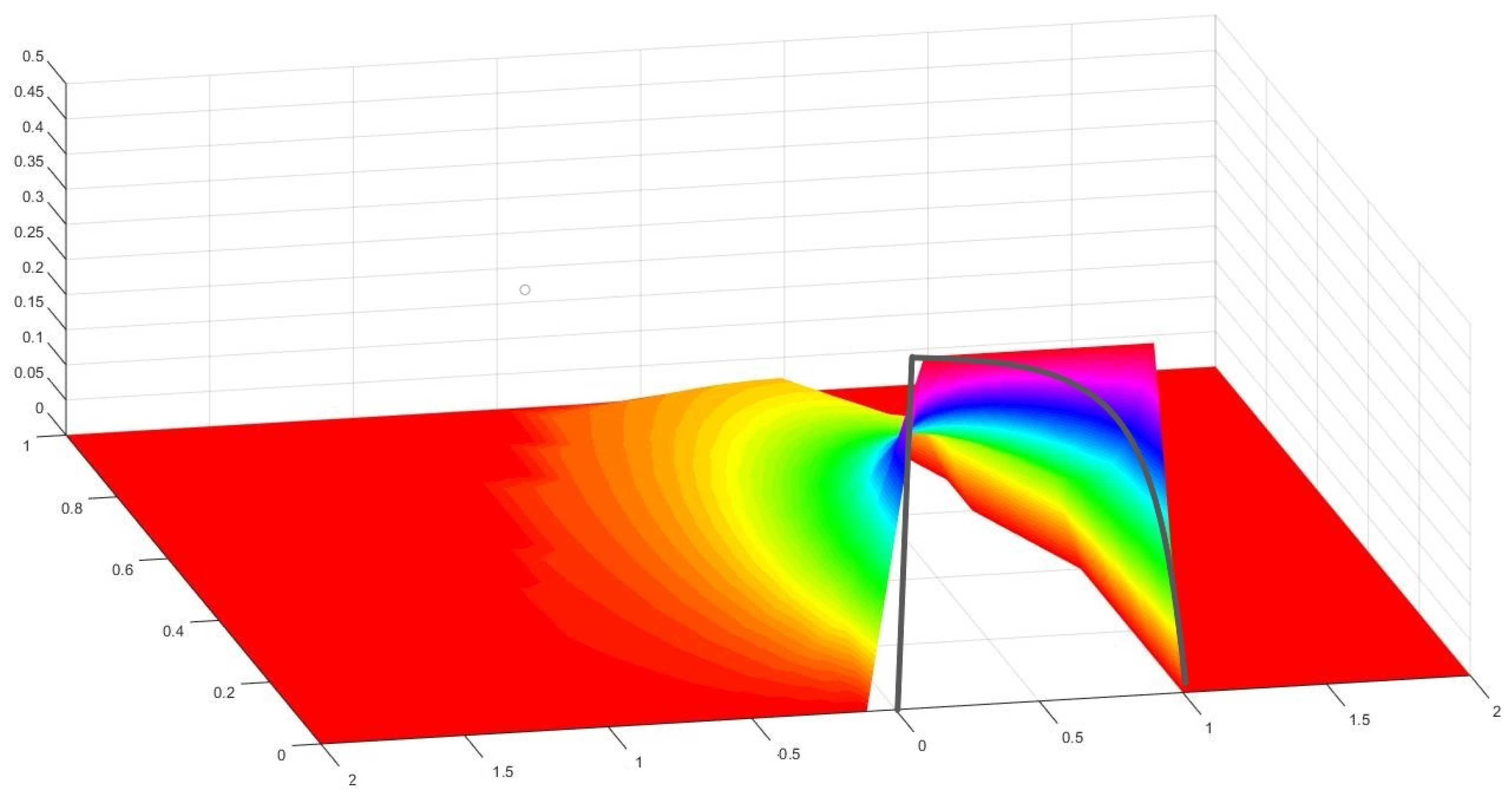
3. Results: Solutions for Various Forms of Circular Sectors
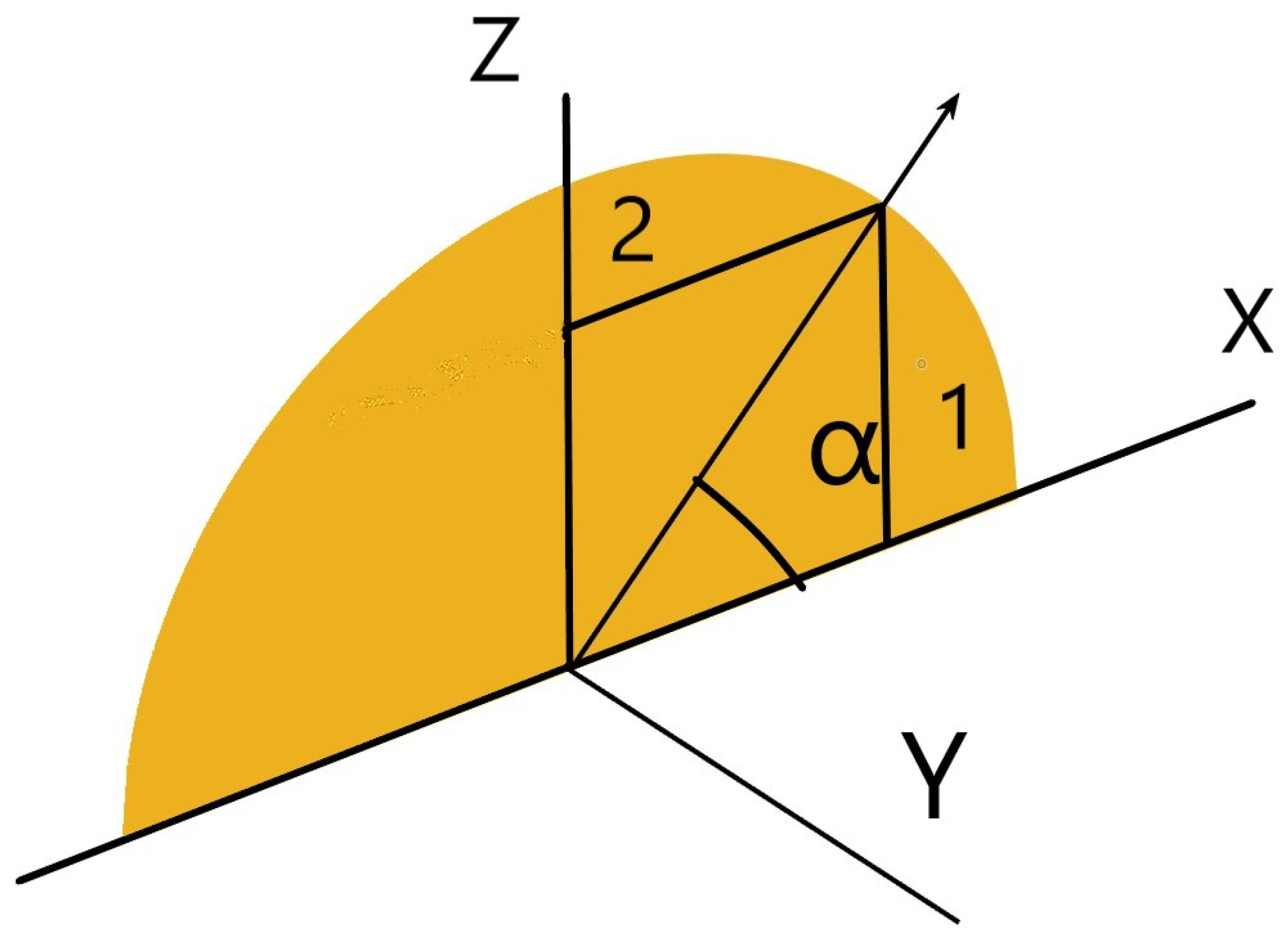
We will summarize and outline below the more important aspects of the integration process (
Figure 3).
In this case, the canonical integral in polar coordinates as mentioned in Equation (5) turns out to be as follows (Equation (6)):
As stated, first we would extend the integral to
π which would represent the whole semicircle. If we integrate with respect to α, in the numerator we would find the derivative of
cosα, −
sinα. Therefore, by making
cosα =
t,
dt = −
sinαdα, this integral reduces to
The primitive is, accordingly, just the quotient of the numerator
Then, the last integral to solve is
whose primitives are a combination of a logarithm and an arc of tangent, for the first term
And substituting, we find
For the second term,
Multiplying by
and grouping, the final result is expressed as
Or in a more developed form,
The same result has been obtained by the author in Cartesian coordinates, see
Appendix A.
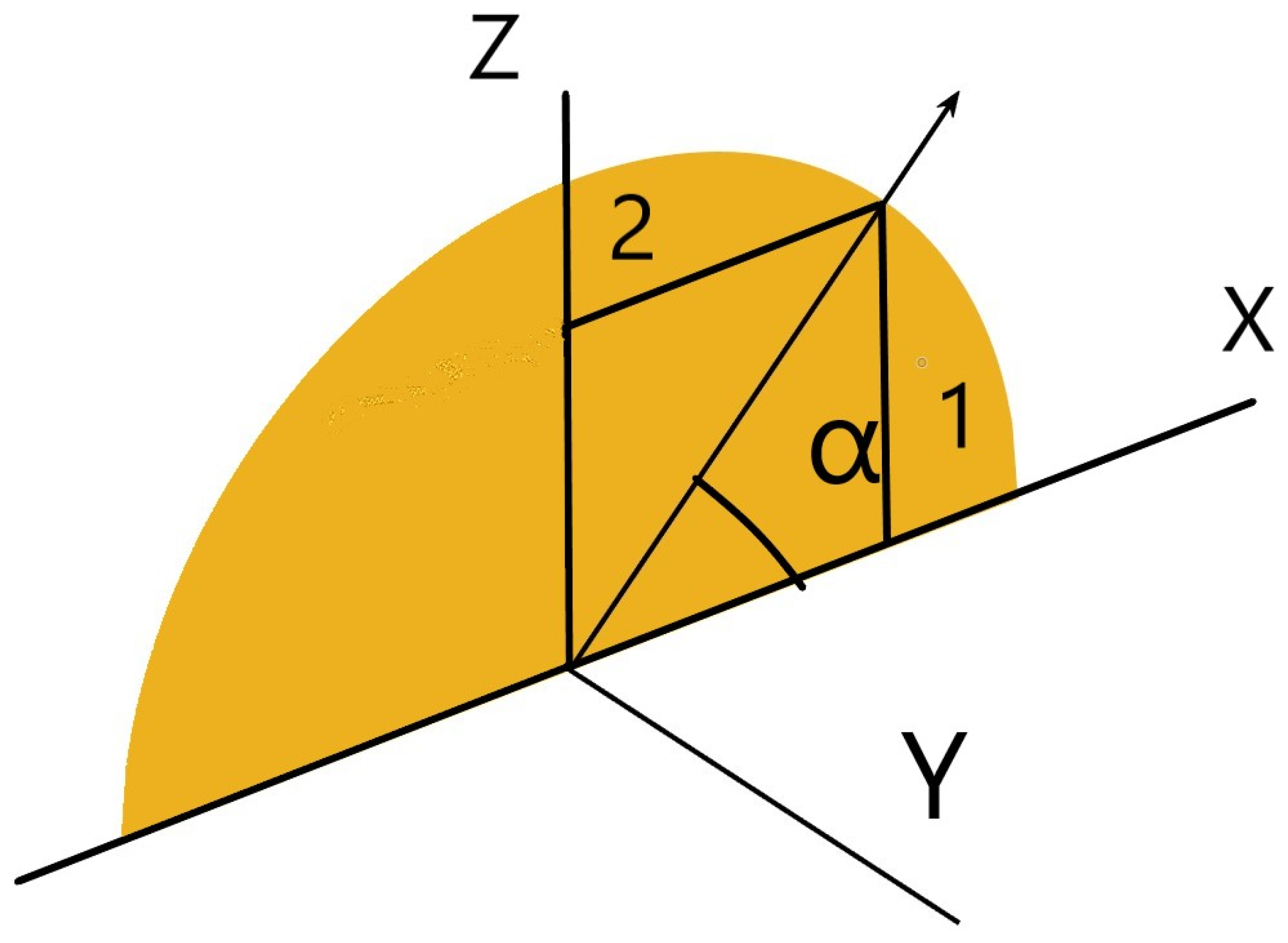
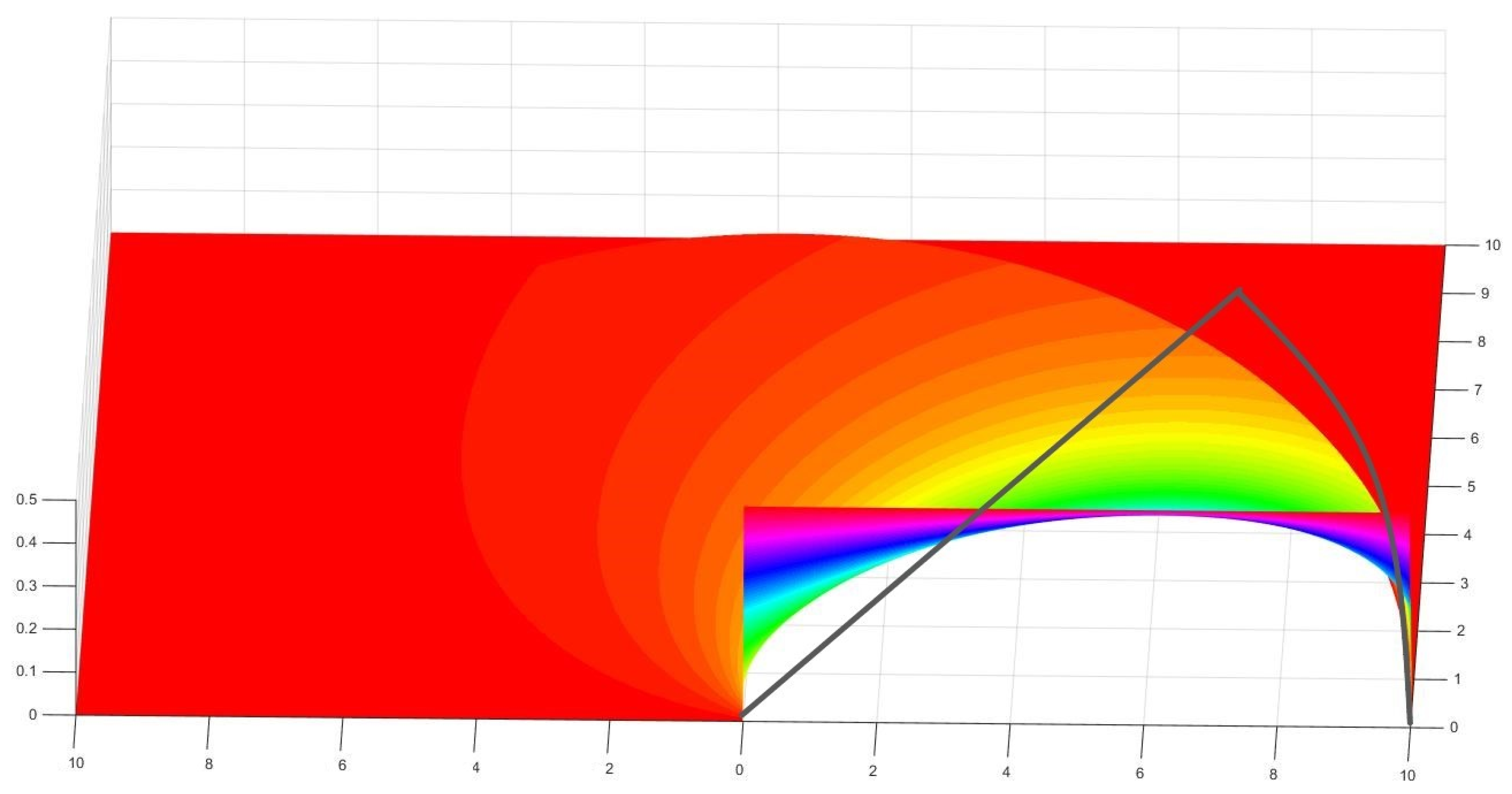
From this result onwards, by using different values of the angle α, (see
Figure 4), we can obtain a number of form factors as follows.
In time, we have been able to solve the same integral not only for the whole angle
π, but in terms of
α, which gives
In the following, we gather a small but representative collection of new form factors depending on the angle subtended by the circular sector [
35].
A further simplification is
And if we call
S =
r +
x and
T =
r −
x, Equation (17) is reduced to
- 2.
For another typical value, the quarter of a circle (angle α = π/2),
- 3.
For the sixth of a circle (angle α = π/3),
- 4.
For the octave of a circle (angle α = π/4),
- 5.
For the twelfth of a circle (angle
α =
π/6),
Thus, for any angular fraction α within the semicircle whose cosine
C goes from 1 (0) to −1 (
π), we receive a new Cabeza-Lainez’s Postulate Number 18 [
36]:
which in formal notation is
By the subtraction of two different α angles,
α1 α2 (with
α2 being larger), we find the form factor for any circular segment at any position within the frame of the semicircle. Substituting (Equation (25)),
as the sum of
arctan (A) and
arctan (B) can be grouped in a single arc of a tangent, if
AB < 1.
But
C1 =
cos(
α1) and (1 −
C12) =
sin2(
α2); therefore, we can write Equation (26).
where
α2 stands for the larger angle (and the lower cosine) and
α1 for the smaller angle, while
r is the radius of the circular sector.
If we make
and
,
4. Possible Combinations of the Former Results
We have already obtained an important and even revolutionary result for some fields of research like, for instance, the lighting and glare avoidance of tunnels and underground facilities [
37] in which there is radiation due to the circular opening (likewise, the radiation from elliptic or parabolic openings is completely unknown). However, by combining these results with others previously obtained by the author of [
38], we can extend the findings much further or apparently without limits.
First, we incorporate the triangle with the circular sector.
The result for the form factor of the triangle with the point moving freely over
x and
y is given in [
12].
If, for instance, we make a triangle with angle
π/4 and we would like the hypotenuse to be
r, as it happens for instance in the octave of a circle, the short sides of the triangle
a =
b would logically be equal to
r∗(√2/2). Substituting a and b into the above formula, it is easy to obtain the following:
However, this is similar to the first term of the result for an octave of a circle (Equation (19)) and we have to assume accordingly that the second positive term, plus the new term found gives, when subtracted,
Or for a general angle
α,
We need to remember that in this particular case,
cosα = √2/2.
Equations (28) and (29) represent the factor introduced by the half circular segment (Region 1 in
Figure 5) that added to the triangle completes the octave. By virtue of this, we have found a new and unbeknownst configuration factor.
If we now add the form factor of rectangles or squares, as the case may be, we can find the corresponding expression for the upper segment of the circle (Region 2 in
Figure 5) which, to our knowledge, has not yet been defined in the literature.
Let us continue the example by introducing a radiating rectangle (square,
a =
b), over a free dimension horizontal plane. The defining equation is, as we know,
The factor for the quarter of a circle is as follows (Equation (21)):
By subtracting both factors, we receive
The factor for the horizontal and vertical segments of a circle outside of the square is
In this particular case,
r equals
a√2,
If we want to obtain the value of the upper segment alone, we need to subtract the factor previously found before:
The operation follows:
And the final result is
with which, we have added a considerable amount of new form factors. Substituting a by
rcosα,
Equation (40) coincides with the generic factor, if we remember that
a =
rsinα =
rcosα as the angle is
π/4, and also because of that,
r =
a√2.
In a more general case, we have the case that for any triangle, the form factor is
But in relation to the radius
r of a circular segment, we know that
a =
rsinα and
b =
rcosα, and substituting,
And, simplifying, this leaves
The final result is
For a generic rectangle with the same substitution of
a and
b, we have
Applying the abovementioned substitution,
The form factor for the generic circular sector is
Then, the vertical segment turns into
And simplifying a bit more,
Accordingly, we can find the upper generic circular segment to the general expression for the quarter of a circle:
We need to subtract the form factor of the rectangle,
But first, we proceed to substitute with the values of
a and
b as a function of the radius.
Then, we perform the first operation to give
And finally we need to subtract the value found for the vertical segment of the circle,
The new generic form factor thus obtained is
Achieving the final results hereby exposed (see
Figure 6).
- 2.
Upper horizontal circular segment:
With adequate adroitness, we can find by addition and subtraction an unlimited number of new form factors [
32], but the emitting surface must be the same for all the bodies involved, usually the larger one [
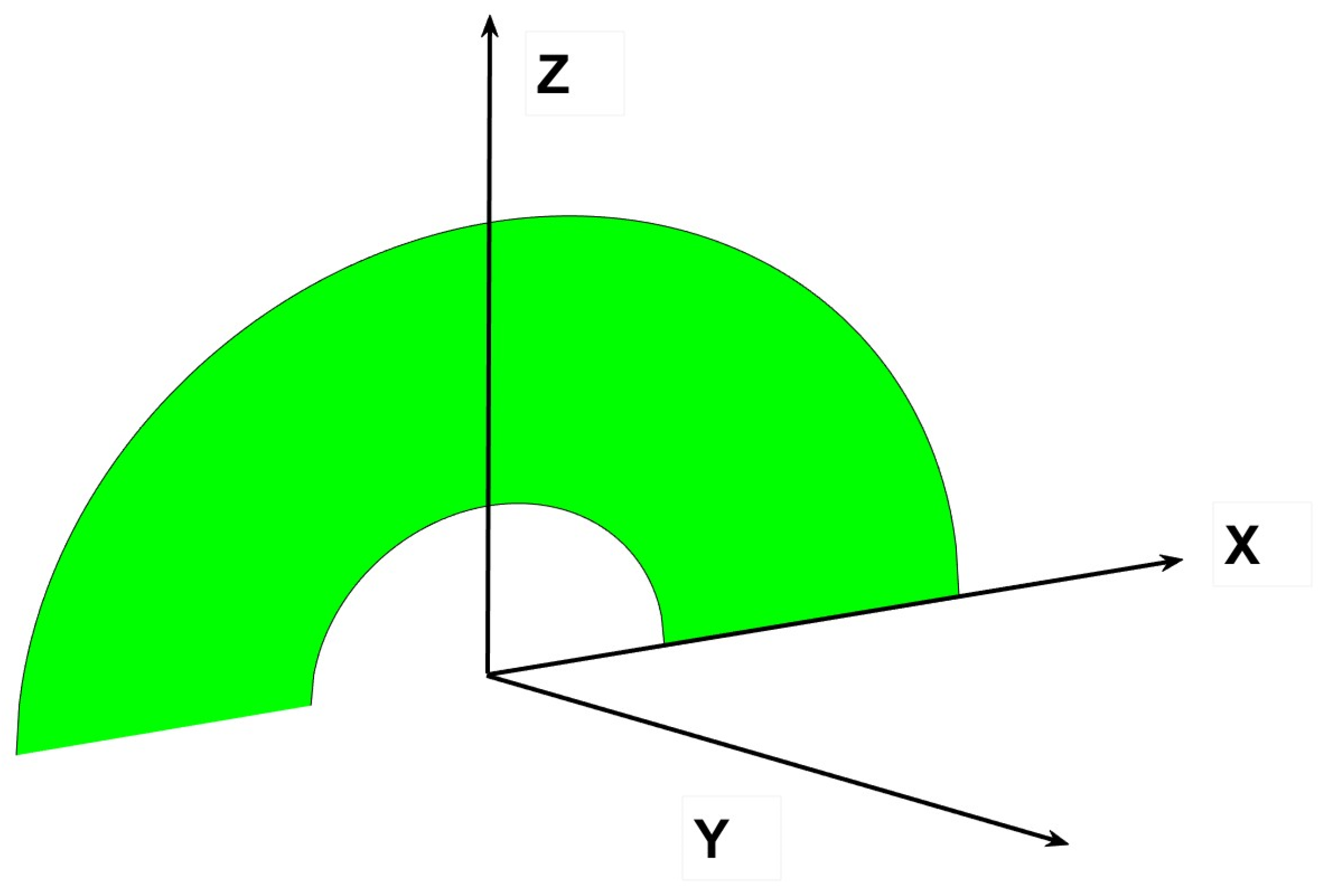
39]. Consider, for instance, the annulus in
Figure 7.
We can find the form factor of a circular ring by subtracting the smaller semicircle from the larger one. The two radiuses are
r and
r1, with
r >
r1. The horizontal surface on which we proceed with the calculations has to be the same for both semicircles, that is, a rectangle or surface larger than the outer half-disk [
40].
6. Complete Three-Dimensional Curved Figures
Having clarified the previous section, we advance towards more complex three-dimensional figures, like for instance sections of a sphere comprised between two quarters of a circle with a common edge. Previously, the author has identified the form factors between semicircles (
Figure 14) at different angles sharing a common edge [
44] and circles with a tangent point (
Figure 15) when their angle of connection is variable [
45], but it was not possible to attempt to find the form factors among Regions 1 and 3 or 2 and 4 in
Figure 16, even less so between alternate quarters of circles like 1 to 4.
In order to perform such a difficult calculation, we start with a trihedron made of two symmetrical quarters of circles (
Figure 17). The base is a circular sector of variable angle α and the cover is a fragment of a sphere of corresponding area α [
46].
The proposed new postulate for the radiative exchange of the two quarters of circles that we will elucidate below is given in Equation (61).
As we can see in the figure, Surface 4 is the fragment of the spherical surface dependent on the angle α, its lateral area is precisely α, the areas of the two symmetrical quarters of circles (named 2 and 3) give an area of π/4, respectively, and the area of the circular sector (1) that serves as the basis for the figure is α/2. If α = π/2, we would receive an equilateral trihedron made of three quarters of a circle.
Then, as usual, by the conservation of radiant energy in an enclosed volume,
We know, by virtue of Cabeza-Lainez’s first law, that
And
F42 =
F43, as they are symmetrical:
From the downwards side, we have three planar circular sectors,
And
F12 =
F13, for symmetry reasons:
F12, can be found with a very precise approximation by means of the formula described in
Section 3 for every angle of the circular sector over a quarter of a circle (
Figure 18); once we have obtained
F12, with the help of such numerical procedure based on the integral, we can proceed with the deductions.
As is known,
But
F42 was from Equation (65),
Substituting,
Thus,
And, including the respective values of the areas in Equation (75),
And finally, we arrive to
However, the respective areas are as follows:
Simplifying with
F12,
Or changing to
F21,
which yields
If
p =
α/
π,
or
remembering that
And introducing
,
We have demonstrated that it is possible to obtain each and every quantity as a function of
F12, and conversely
F21, and more importantly we have demonstrated the new Cabeza-Lainez postulate for quarters of circles with a common edge [
47,
48].
The former Cabeza-Lainez law for semicircles was as a function of the angle
α,
However, this law was independent of any previously found factor. In terms of
p,
And the former law is
For the record, the postulate for whole circles in terms of
p is
Now, we can compare the three laws obtained with difficulty in
Figure 18.
Adding as a novelty the form factors between alternate quarters of circles, we produce
Figure 19.
Check for Validity
A demonstration of validity is given by a simple example [
49], for a quadrant, octave of a sphere or curved trihedron.
In this case
α =
π/2, and as stated previously, we know by virtue of Cabeza-Lainez’s first law that
Therefore,
Thus, since
F41 and
F42 and
F42 are equal and symmetrical,
As
A4 is
π/2 and the area of each quadrant is
π/4,
A4 = 2
A1,
Equally,
From Equation (97),
But, as before,
F12 and
F13 are equal and symmetrical; consequently,
And the problem is completely solved, since
as in Abscissa 51 in
Figure 17, with a value of 0.208.
With a similar approach, the total form factors can be found for the usual sets of precincts, such as prisms or oblique cuboids. Inter-reflection within the so-generated volumes is also an issue that we have to foresee; in the case of triangular prisms, we would require a set of five equations with five unknowns, but in the case of the octave of sphere explained above these reduce to four equations which are detailed at
Appendix B [
50].
In another different example, when designing and solving inclined slats, the triangles that appear are not right, but usually they come as obtuse or acute angles. In these situations, we cannot employ the already-solved form factor for perpendicular rectangles or cuboids [
5]; instead, we need to resort to different extended formulas developed by the author of [
51] to take into account the said exchanges between inclined rectangles.
8. Conclusions
Throughout this manuscript we have demonstrated by means of accessible calculus operations how to obtain the solution to certain complex integral equations that provide us with more than five new postulates of radiation between circular sectors, ellipses, circular segments and the interaction between those and figures like the quarter of a circle, the triangle and the rectangle. Such effort will undoubtedly contribute to the solution of numerous radiative problems that have hindered the development of technology in diverse fields.
Certainly, integral equations are a problematic domain of mathematics but they are mandatory to advance solutions to the many problems of radiative heat transfer, as they are frequently colligated to surface emission and demand an exact solution.
In the mathematical process followed to improve the level of knowledge in the realm of radiative transfer, it is possible to outline the exactitude and feasibility of the solutions, the introduction of novel variables and the new form of addressing inter-reflections for curved surfaces. Also, the combinations with different geometries constitute an important innovation.
Semicircles and other derived figures have been employed in a great number of artifacts and industries since early epochs, and now finally are we able to determine with total accuracy their performance under a significant number of situations in radiative heat transfer. However, a detailed logical approach had not been attempted in the past because of the mathematical hindrances arising in the process. The solutions provided are especially feasible for the design and retrofit of tunnels, lighting elements from circular windows to LED emitters and also aircrafts’ parts affected by radiation.
The relevant novelties that these postulates entail also lie in the question of how they have been implemented in simulation algorithms. We firmly believe that given the preparedness for application that they present, they will radically transform and sometimes ignite processes based on the transfer of radiation, whether natural or artificial. In this fashion, fundamental issues of radiative heat transfer can be treated in an accurate and assertive manner to boost knowledge on sophisticated forms of energy. Thus, we hope that consequences of great significance can be derived from the current research if time provides.


