In this section, we analyze the exact BER expression for both the conventional NOMA and the proposed NOMA. In this paper, it is assumed that the data for user 1 and user 2 are modulated by QPSK. Each user’s symbol is detected as one of , assuming that the priori probabilities of each symbol are equal, and each symbol is modulated according to QPSK as {}.
4.1. Exact BER of Conventional NOMA
In the conventional NOMA system, both user 1 and user 2 decode the received signal to detect
. Additionally, user 1 detects and removes
to decode its own signal,
. Therefore, the error probability for
at user
k is first calculated. In QPSK modulation, since each symbol consists of 2 bits, the probability that user
k fails to decode
can be expressed as the average of the error probabilities for the first and second bits of
, as follows:
where
denotes the event that user
k incorrectly detects
and
denotes the event that user
k incorrectly detects the
j-th bit of
(
) [
8].
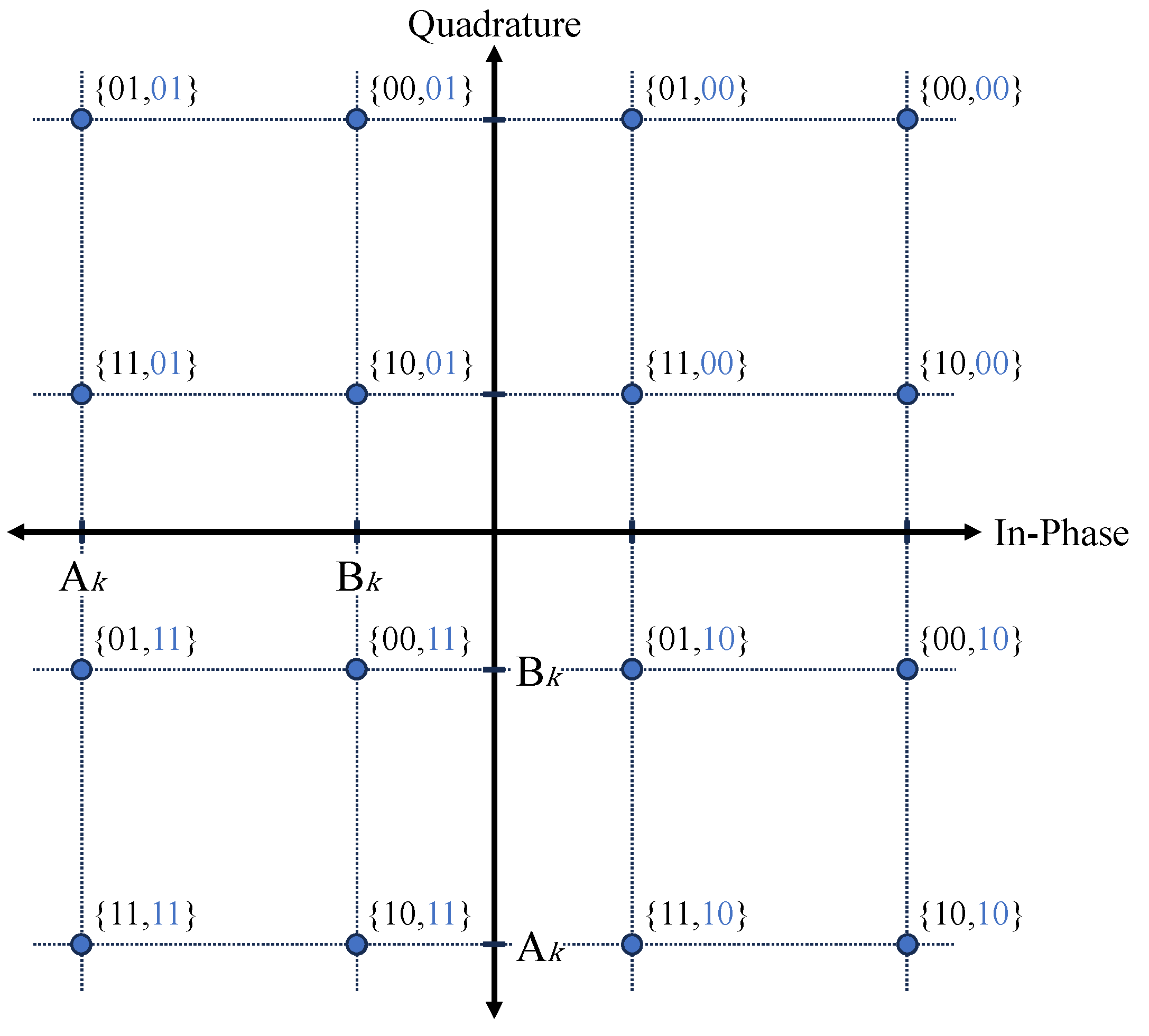
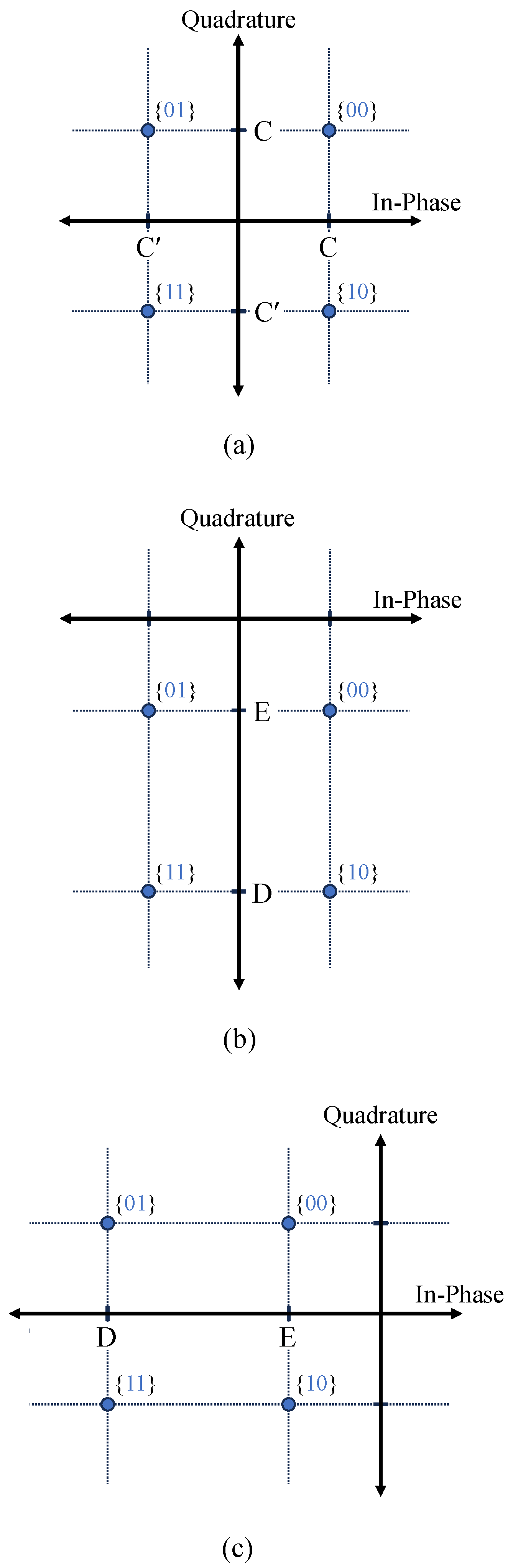
Figure 4 shows the constellation diagram of the signals received by each user in a conventional NOMA system. Each point represents the combination of signals
and
under SC. It is denoted as
, and the received signals at each point are expressed by (5) as
.
In
Figure 4, an error occurs if any point on the constellation diagram deviates from its appropriate decision region. It is evident that the first bit of the QPSK symbol is determined by the quadrature part, and the second bit is determined by the in-phase part. For instance, if the actual first bit of
is 1, in order to detect the first bit correctly, points
and
should be located below the boundary of the decision region. The second bit can also be approached in the same way as before. That is, since user
k mistakenly decides bit 1 as 0 when point
or
is greater than 0,
and
can be expressed as follows:
where
denotes the event that user
k incorrectly detects the
j-th bit of
due to the position of point
i (
). By substituting (
5) and the QPSK symbols, (
13) can be expressed as follows:
where
and
denote the in-phase and quadrature components of the noise, respectively, and
is the symbol energy,
[
9]. By substituting (
14) into (
12), the error probability of user 2 is defined as follows:
where
Q(·) denotes the Gaussian
Q function. The simplified expression of (
15) is as follows:
where
is the SNR for the
i signal points given in
Figure 4. For
,
can be expressed as follows:
Then, the average BER at user 2 can be obtained as follows:
where
is the probability density function (PDF) of SNR. In this paper, assuming a Rayleigh fading channel, the PDF of the SNR is defined as follows:
where
denotes the average of
.
Using ([
10], Equations (13.3)–(7)) and (
19), (
18) is given as follows:
Next, user 1 decodes
after performing SIC to remove
. The error probability of user 1 depends on whether
is detected correctly or incorrectly. Therefore, the error probability of user 1 is defined as follows:
where
denotes the complement of
.
Figure 5a shows the constellation of
after user 1 correctly detects
and performs SIC. The expressions for each signal are derived from the signal expressions in
Figure 4 with the terms containing
removed. Therefore, the signal at each point is expressed as
. For the correct detection of the bits in
, the points C or C′ on the in-phase and quadrature axes should not fall outside their respective decision regions.
User 1 incorrectly detects the first bit of
if either
or
, and incorrectly detects the second bit of
if either
or
. Hence, the bit error probability of user 1, under the condition that no error occurs when detecting
symbols, is given as follows:
where
and
are the probabilities that user 1 correctly detects the
j-th bit of
as given in (
13). If the fundamental theorem of conditional probability,
, is applied, (
22) can be redefined as follows:
For the purpose of simplifying (
23), we define the SNR for the C or C′ signal point given in
Figure 5a as follows:
Then, the error probability of
, given that user 1 correctly detects
, is expressed as follows:
Figure 5b,c show the constellations of
after user 1 incorrectly detects
and performs SIC. These represent the cases where the first bit of
is in error and where the second bit is in error, respectively. The expressions at points D and E, contrary to the case of
, represent the in-phase and quadrature components of the signal, respectively, where terms containing
or
are not removed, but instead added to the signals in
Figure 4:
. In
Figure 5b, user 1 incorrectly detects the first bit of
if either
or
, and incorrectly detects the second bit of
if either
or
. Similarly, in
Figure 5c, user 1 incorrectly detects the first bit of
if either
or
, and incorrectly detects the second bit of
if either
or
. Hence, the bit error probability of user 1, under the condition that error occurs when detecting
symbols, is given as follows:
where
and
are the probabilities that user 1 incorrectly detects the
j-th bit of
as given in (
13). Similar to (
23), (
26) can be redefined as follows:
For the purpose of simplifying (
27), we define the SNR for the D and E signal point given in
Figure 5b,c as follows:
Then, the error probability of
, given that user 1 incorrectly detects
, is expressed as follows:
By substituting (
25) and (
29) into (
21), the error probability of user 1 is obtained as follows:
Then, the average BER at user 1 can be obtained as follows:
Using ([
10], Equations (13.3)–(7)) and (
19), (
31) is given as follows:
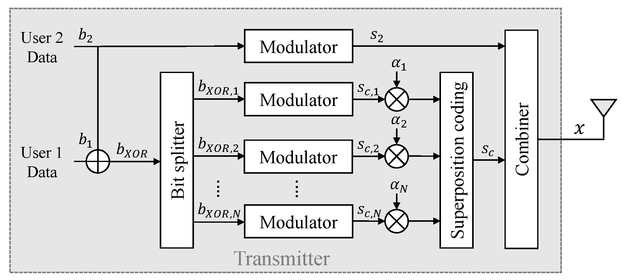
4.2. Exact BER of Proposed Transmitter and Receiver
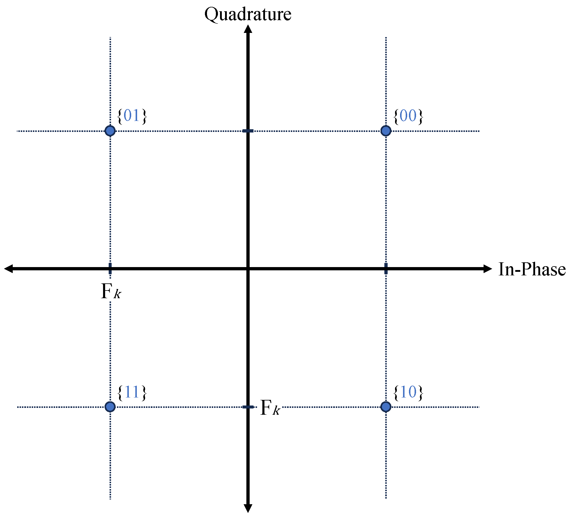
In the proposed method, the transmitter sends two types of data: one is the information for user 2, and the other are the redundancy data used to transform the former data into the information for user 1. In this method, user 2 only requires the former data, while user 1 requires both the former and the latter data. Therefore, we proceed by separating the former and latter data to calculate the error probability. In this section, we assume
. First, the constellation diagram of the former data is represented as shown in
Figure 6.
The received signals at each point are expressed as
. User
k incorrectly detects the first bit of
if
, and incorrectly detects the second bit of
if
. Thus, the error probability for
at user
k is expressed as follows:
To simplify (
33), SNR at points
can be expressed as follows:
By substituting (
34) into (
33), the error probability of user 2 is defined as follows:
Then, the average BER at user 2 for the proposed receiver can be obtained as follows:
Using ([
10], Equations (13.3)–(7)) and (
19), (
36) is given as follows:
Next, for user 1, the error probabilities of both
and
should be considered. The error probability of
is the probability of incorrectly detecting
, and the error probability of
is the probability of incorrectly detecting
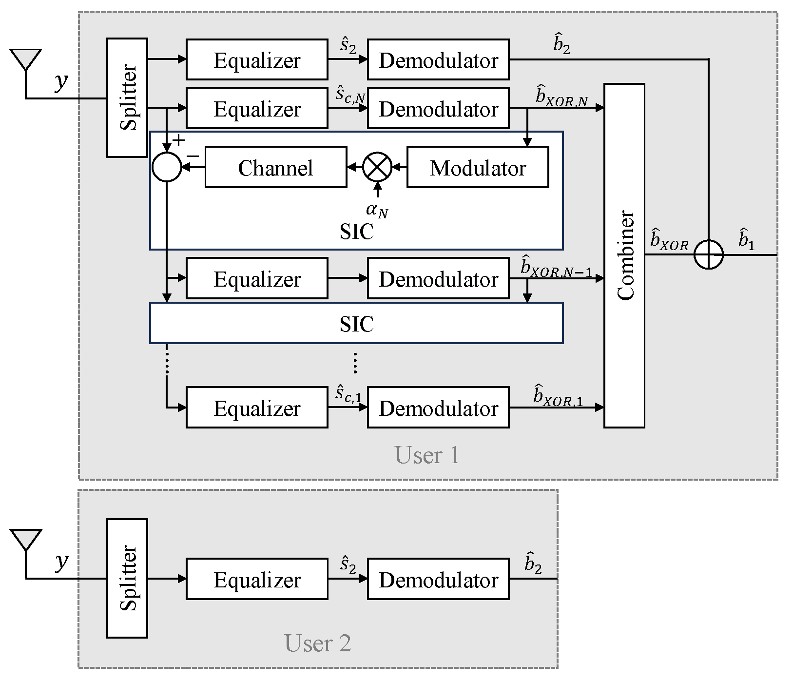
. Examining the error probability of user 1, the XOR bit operation results in 1 when the two bits are different, and 0 when they are the same. Due to this characteristic, if both
and
are incorrectly detected, the final
obtained in
Section 3.2 would be detected without error. Therefore, the error for user 1 occurs only when either
or
has an error. The average error probability of user 1 in the proposed receiver is expressed as follows:
where
denotes the event that user 1 incorrectly detects
. Due to (
33) and (
34), the error probability of
for user 1 is given as follows:
Then, the average error probability of
at user 1 is given as follows:
Since
is a combination of
and
combined in series, its average error probability for user 1 can be represented as the average value of the error probabilities for the
and
of user 1 in conventional NOMA, as follows:
By substituting (
12) and (
32), (
41) is obtained as follows:
By substituting (
40) and (
42) into (
38), the average error probability of user 2 is given as follows:


