Article

An Enhanced Extremum Seeking-Based Energy Management Strategy with Equivalent State for Hybridized-Electric Tramway-Powered by Fuel Cell–Battery–Supercapacitors

by
Hoai Vu Anh Truong
1,
Hoai An Trinh
2,
Tri Cuong Do
3,
Manh Hung Nguyen
4,
Van Du Phan
5 and
Kyoung Kwan Ahn
4,*
1
Department of Mechanical Engineering, Pohang University of Science and Technology (POSTECH), Pohang 37673, Republic of Korea
2
Faculty of Electronics, Telecommunications Saigon University, Ho Chi Minh City 700000, Vietnam
3
College of Technology and Design, University of Economics, Ho Chi Minh City 700000, Vietnam
4
School of Mechanical and Automotive Engineering, University of Ulsan, Ulsan 44610, Republic of Korea
5
School of Engineering and Technology, Vinh University, Vinh 43108, Vietnam
*
Author to whom correspondence should be addressed.
Mathematics 2024, 12(12), 1849; https://doi.org/10.3390/math12121849
Submission received: 16 May 2024 / Revised: 5 June 2024 / Accepted: 12 June 2024 / Published: 14 June 2024

Abstract

:
This article proposes a novel real-time optimization-based energy management strategy (EMS) for proton membrane exchange fuel cell (PEMFC)-battery-supercapacitors-driven hybridized-electric tramways (HETs). The proposed algorithm is derived based on an enhanced extremum seeking (ES) algorithm, with a new equivalent state-of-charge (SOC) and a new adaptive co-state introduced. Thereby, optimized reference power for each power source can be distributed appropriately when using three components. The workability and prominent of the proposed technique are demonstrated through comparative simulations with fuzzy-rule-based EMS (FEMS) and equivalent consumption minimization strategy (ECMS) in two case studies: with and without considering the supercapacitors, as an important factor in the EMS design to stabilize the SOC of energy storage devices (ESDs). Briefly, under the proposed ES-based method, the PEMFC power can be regulated such that high-efficiency can be performed, approximately by 46.7%. Subsequently, the hydrogen consumption is reduced about 31.2% compared to a comparative fuzzy-based EMS. Besides, the supplements’ SOCs at the end of a driving cycle are also regulated to be equal to the initial ones.

1. Introduction

1.1. Literature Review

In the past few years, developing control strategies for hybrid electric tramways (HETs) or locomotives has turned into an interesting topic in the field of designing and finding solutions to efficiently utilize hybrid power sources (HPSs) for hybrid electric vehicles. Among various prototypes, the paradigm of a proton exchange membrane fuel cell (PEMFC) interconnected with single or multi-energy storage devices (ESDs) is believed to be a potential alternative for HETs [1,2,3]. Numerous energy management strategies (EMSs) have been introduced. Essentially, rule-based control and optimization-based control are two representative approaches.
The rule-based method is a real-time control strategy based on engineering heuristic experience, which can be simply applied to practical hybrid systems, such as state machines [4,5,6], frequency-decoupling [7], and so on. However, it cannot be generalized to any objective as the execution of this manner significantly depends on the expert knowledge of designers. Besides, it is not able to satisfy the optimal solution. On the contrary, optimization-based techniques, including global and real-time categories, can help optimize the system’s performance.
Specific global optimizations such as dynamics programming, genetic algorithms, particle swarm algorithms, equivalent consumption minimum strategy (ECMS), and so forth have been successfully deployed for several objectives such as electric vehicles [8,9,10,11,12] and construction machines [13,14]. Of the HETs, in [15,16], the authors focused on designing an EMS on the basis of the ECMS manner for the PEMFC-supercapacitor (SC) HETs to optimize operation speed and minimize fuel consumption. In [17], Li et al. developed an EMS by using an online ES-based adaptive recursive least square for PEMFC-SC HET.
Most systems in the literature employed the integrated PEMFC-SC setup, in which the PEMFC is used as the primary supplying power to the whole system whereas the SC functions as a supplementary. Of the higher-power electronic systems, either a bigger size of the PEMFC unit is required, which increases operating and maintenance costs, or the PEMFC has to operate in the high-power region with low efficiency, regarding the PEMFC characteristics and its efficiency map, when using the small-size PEMFC units. To solve this issue, the battery can take place the SC to share the power endurance of the PEMFC and lower the size of the PEMFC. In [18], Peng et al. investigated the PEMFC-Battery configuration for a hybrid railway and proposed a dynamic programming-based adaptive rule-based EMS to optimize the PEMFC power and prolong its lifetime. Subsequently, Deng et al. developed Pontryagin’s Minimum Principle-based model predictive control to perform the optimal power reference for each device and lower the fuel economy [19]. Coming up with PEMFC-Battery hybrid locomotives, the authors in [20] focused on optimizing component size to minimize the overall cost based on the student psychology optimization method. However, due to the battery characteristics, this setup may not satisfy abrupt changes in time. Therefore, this is the first motivation for us to examine a hybrid system for the HET where both battery and SCs can be simultaneously retrofitted to inherit individual advantages and support for the PEMFC.
Although the HPS of three devices has potential and was verified with both simulations and experiments, most works just focused on the PEMFC and battery dynamical behaviors in the EMSs design without investigating the SC dynamical performance. This component freely operates only to either maintain or suppress the fluctuation of the DC bus voltage. Few papers have considered all segments’ behaviors. For example, regarding electric vehicles, the rule-based EMSs for this hybridization were studied in [21,22]. In [23], Truong et al. developed a fuzzy-based EMS to establish power distribution for each source. As the limitation of the rule-based approaches when they are not able to exhibit an optimal solution and require a lot of heuristic efforts, Yi et al. employed dynamic programming to achieve the optimal solution in the EMS design [14]. Subsequently, Dao et al. [24] proposed an optimization-based EMS by combining a backtracking search algorithm and sequential quadratic programming to solve the problem of optimization. Recently, Li et al. proposed a novel online ECMS for the hybridization of three devices but for electric vehicles [25]. Despite that good performance was verified, these techniques are of global optimization with burden and offline computation implemented. Moreover, those papers contributed to the objectives of electric vehicles and construction machinery. Hence, there is still a gap in applying the hybridization of PEMFC-Battery-SC for the HETs, which inspired this article.
Concerning the HET, Garcia et al. constructed an ECMS for the hybrid PEMFC-Battery-SC [26]. Yet, the authors neglected the SC behavior in the EMS design. Li et al. [27] proposed a Harr wavelet transformation fuzzy logic technique to conduct an EMS. Peng et al. [28] developed a master-slave hysteresis state machine based on the fuzzy technique for the EMS design. In the latest contribution to HET, Trinh et al. [29] investigated an HPS of PEMFC-Battery-SC where SC was involved in the designed EMS. Yet, these accomplishments belong to the rule-based approach, which can only contribute to a suboptimal solution. In terms of optimization-based approaches, Zhang et al. [30] investigated the PEMFC-Battery-SC HET for an ECMS-based EMS execution. However, the authors neglected the SC consumption in the cost function where the SC operated freely without any constraint and was just used for absorbing peak and transient load power. Despite being well known as a powerful optimization method, the ECMS requires internal parameters such as charged and discharged resistors and coefficients corresponding to each circumstance to execute the equivalent consumption and objective function, which may meet difficulty in achieving good system identification. Besides, the ECMS is a typical global optimization method, which offers offline implementation and requires predetermined or well-known driving cycles.
Compared to global optimizations, real-time optimizations bring the benefit of flexibly fulfilling load variations with online updating. In [31], Wang et al. proposed a hierarchical power distribution based on the ES technique for the HET with a novel configuration of dual PEMFC battery. The ES is useful to seek out the optimal working point due to its advantages [32]. More results of using ES can be found in [32,33]; however, these approaches have been developed and applied for electric vehicles, and they only considered two power sources.

1.2. State-of-the-Art

From the EMS design point of view, regarding the literature and discussions above, the rule-based EMS (such as state machine, deterministic method, fuzzy-based EMS) is of a real-time control strategy, but it cannot be generalized to any objective because the implementation of the rule-base EMS significantly depends on the expert knowledge of designers and cannot meet the optimal solution. Therefore, this type of EMS is used as a baseline control strategy for comparison.
The global optimization control method, such as dynamic programming, genetic algorithm, and so forth, can exhibit a global optimum; however, it belongs to the offline control strategy that remains a drawback of well-known or prior determined driving cycles requirement, thus restricting the real-time executions. Moreover, this manner brings a burden calculation because it demands a library of all driving cycle information. Some other methods, such as the ECMS and Pontryagin’s minimum principle, need the parameters of the system dynamics and components to generate the objective function, which requires more effort in practical applications. Hence, they are mostly considered as a benchmark for comparisons.
Meanwhile, the real-time (or local optimization)-based EMS, such as extremum-seeking, model predictive control, adaptive control, and so on, is not only suitable for real-time applications but is also able to exhibit an optimal solution; however, it is easy to meet local optima. Among those, the model predictive control is a good choice for real-time EMS design due to its capability of predicting and solving optimization problems. Nevertheless, this method requires heavy computation [32]. The extremum seeking, on the contrary, offers a simpler calculation to seek out the maximum efficiency of the PEMFC. Despite the local optimization category, it is suitable for the EMS design because the PEMFC efficiency map uniquely has one highest efficiency point; thus, the problem of local optima does not affect this situation [32,33]. To this end, the state-of-the-art with merits and demerits for each control strategy is summarized in Table 1.
From the hardware setup for HETs point of view, the literature just considered two devices for the hybrid system configuration, one primary source of the PEMFC and one supplementary source of either the battery or the SC. Some studies dealt with the PEMFC-Battery-SC hybridization; however, the dynamical behavior of the SC was ignored in the cost function and optimization problem.

1.3. Motivations and Contributions

Motivated by the above observations, this paper presents an optimization-based EMS employing a modified ES technique as the core idea to achieve power distribution for three devices of PEMFC-Battery-SC HPS for the first time. The ES approach is used to obtain the PEMFC reference optimal power. To make this control framework implementable, a new equivalent state-of-charge (SOC) is suggested that allows reducing the number of auxiliary variables to simplify the control design. As the usage of the equivalent system, an additional rule is conducted to distribute the remaining power for each auxiliary segment. To this end, the contributions of this work are as follows:
(1)
Different from existing works that utilize the ES approach, this work applies a new methodology to facilitate the ES-based control framework to deal with multiple supplements for power distribution by expressing an equivalent component.
(2)
A new penalty function is introduced with the PEMFC power and its change rate is included besides the standard former [32,33]. With this objective function, the PEMFC power can be more effectively regulated to operate in the high-efficiency region with smooth response whereas the SOCs of the ESDs are maintained to vary in the suitable intervals.
(3)
The comprehensive controlled system with high- and low-level control units is presented with more details of the control structure and compensation regarding each device’s characteristics. The effectiveness of the proposed strategy is then verified through comparative simulations with another real-time optimization and baseline fuzzy-based EMS.
In summary, the innovations of this paper include: (i) First time applying the modified ES-based EMS for hybrid HETs driven by a hybrid PEMFC with multi-supplement ESDs; (ii) introducing an equivalent SOC with an adaptive co-state, which reduces the number of multi-supplement to facilitate the control strategy implementation. Accordingly, the ES-based algorithm can be conventionally derived; (iii) presenting a new penalty function to extract the PEMFC optimal and smooth power reference; and (iv) introducing a load ratio to specify the power reference of the battery and SCs based on the equivalent SOC and adaptive co-state.
The rest of the paper is organized as follows: The models of the hybrid tramway with HPS, including DC-DC converters, is described in Section 2. Accordingly, the proposed EMS implementation with comprehensive high- and low-level control is explained in Section 3. Section 4 validates the workability and prominence of the proposed method in comparison with other online-updating and offline-computing approaches. Finally, Section 5 summarizes the main results and discusses further improvements.

2. System Descriptions

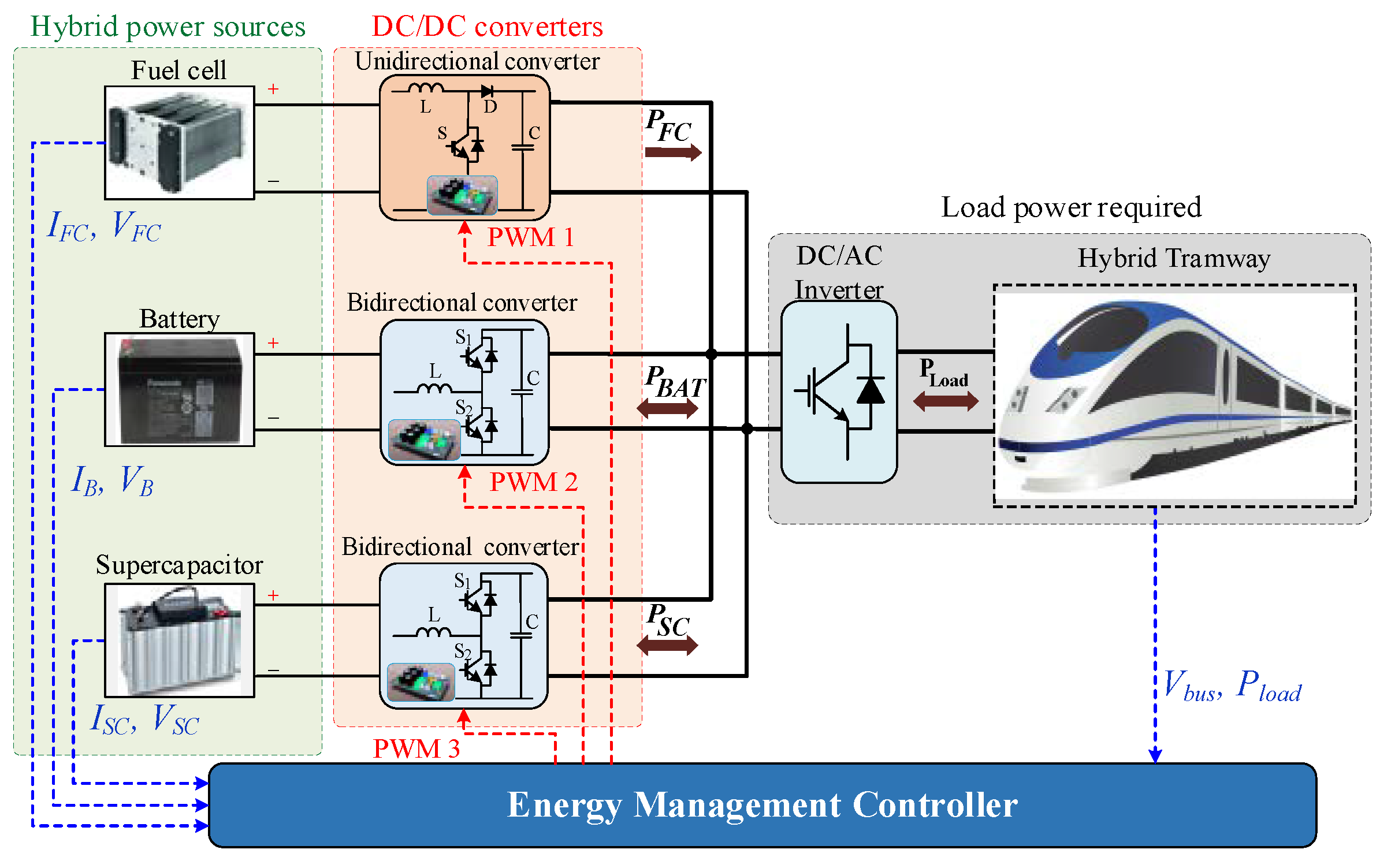
2.1. Power-Train Architecture

The comprehensive examined model is configured with the PEMFC, battery, a bank of SC (bSC), DC-DC converters, and load requirements (DC-AC inverters, traction load, and tramways dynamical model), and EMS system as described in Figure 1.
The HPS is interconnected to the DC bus through DC-DC converters to satisfy the load power demand. In this manner, the PEMFC is designated as a primary supply whereas ESDs (battery and bSC) provide power during the acceleration, going uphill; absorb the regenerative energy in the braking process or going downhill; and compensates for or consumes the peak transient power of the traction load that the PEMFC cannot accommodate in a short time. The EMS block aims to distribute power for each power source appropriately. Each component’s dynamics model in the HET system is discussed to perform the system behavior and evaluate the effectiveness of the proposed EMS. The following subsections outline the specific features of the PEMFC, battery, SC, and DC-DC converters.

2.2. PEMFC Model

In this study, the PEMFC is considered the primary source. This device is assembled with a certain number of stacks and auxiliary subsystems. The system dynamics can be systematically modeled with reactants using mathematical equations [34,35]. Based on the system modeling and system characteristics, the PEMFC hydrogen consumption, m ˙ H 2 (g), can be obtained from the polarization of [36,37]:
m ˙ H 2 = { α 1 P F C 2 + α 2 P F C + α 3 if   P F C < P F C l ( low   power ) α 4 P F C + α 5 if   P F C P F C h ( high   power ) ,
where αi, (i = 1, …, 5) are PEMFC’s state-dependent coefficients; P F C l and P F C h are, in turn, the lower and upper bounds that represent high-efficiency region (low power) and low-efficiency region (high power).
Regarding the power fed for auxiliary subsystems (cooling fan, heating system, pumps, and so on), the PEMFC efficiency can be computed by
E f f = P F C P t o t × max ( 0 , 1 P a u x P F C )   ( % ) ,
where Ptot, Paux, and PFC are the total power (kW), power required to supply for auxiliary subsystems, and output net power of the PEMFC system, respectively, that satisfy
Ptot = Paux + PFC (kW),

2.3. Battery Model

As discussed, the battery is integrated to mainly share the load power withstanding from the primary source and store regenerative energy during the deceleration and braking processes. The simplified model of the battery is inherited from [24], and the time-varying battery SOC, denoted by SOCB(t), is obtained as
S O C B ( t ) = S O C B ( t 0 ) + 1 Q B , max V B , r a t e d t 0 t P B ( τ ) d τ ,
where SOCB(t0) stands for a value at the initial time t0; QB,max is the maximum capacity of the battery; VB,rated is the rated voltage (V); and PB(τ) is the output battery power.

2.4. Supercapacitor Model

The SC is involved in absorbing the peak and transient phase of the current load owing to the advantage of fast dynamics response. The SC simplified model is obtained based on the equivalent circuit as [24]
i S C ( t ) = V S C ( t ) V S C 2 ( t ) 4 R S C P S C ( t ) 2 R S C   ( A ) ,
with the SOC of the SC, denoted by SOCB(t), being
S O C S C ( t ) = S O C S C ( t 0 ) + 1 Q S C , max V S C , r a t e d t 0 t P S C ( τ ) d τ ,
where iSC(t) (A), VSC(t) (V), PSC(t) (kW), and RSC (Ω) are the SC current, SC open-circuit voltage, SC internal resistance, and SC power at the instant time t, respectively; SOCSC(t0) is the value at the initial time t0; QSC,max denotes the maximum capacity of the SC; and VSC,rated is the rated voltage (V).

2.5. Modeling of DC-DC Converters

DC-DC converters are adopted to guarantee the capability of energy sources, regulate DC bus voltage, and output net power of each source for the load demand satisfaction. According to the HET architecture, two types of DC-DC converters are considered: a unidirectional DC-DC converter for the PEMFC and a bidirectional DC-DC converter for the ESDs to transfer the power flow in both directions for energy delivery and recovery tasks. In this study, these converters are designed based on the switching model controlled by using pulse-width modulation (PWM) signals, whose structures are performed in Figure 2 [35].
Generally, both types consist of high-frequency inductor L, two filtering capacitors C1 and C2, resistor R, power source Vin, one switch S with a diode D for the unidirectional converter, and two switches S1 and S2 for the bidirectional converter. For this type, it is noteworthy that when switch S1 is activated, switch S2 serves as a diode component and the converter operates with boost mode, thus increasing the output voltage to meet the load demand. In contrast, if switch S2 is activated, switch S1 works as a diode component; the converter acts in buck mode that steps down the voltage in the DC bus and charges the battery or SC. The output voltage of these converters in boost mode and buck mode can be calculated as follows:
V o u t _ b o o s t = V i n _ min η b o o s t 1 D b o o s t ,
V o u t _ b u c k = V i n _ max η b u c k 1 D b u c k ,
where Vout_boost and Vout_buck are the output voltage of the converter in boost mode and buck mode (V), respectively; Vin_min and Vin_max are the minimum and maximum input voltage of the converter (V), respectively; Dboost and Dbuck are the duty cycle of boost mode and buck mode (%), respectively; ηboost and ηbuck are the converter efficiencies of boost mode and buck mode, respectively, which are estimated to equal 80–90%.

3. Proposed ES-Based EMS for the Hybrid Tramway System

This section presents a comprehensive control scheme with high-level control for the EMS and low-level control for the DC-DC converter for PWM implementations. The high-level control aims to determine the appropriate power command for each source whereas the low-level control is to regulate the DC bus voltage and generate output power to meet the reference one obtained from the high-level control.

3.1. PEMFC Reference Power

The ES-based optimization method aims at seeking out and optimizing the PEMFC power, at which the maximum efficiency is attained, whereas the SOCs of both battery and SCs are regulated within the suitable range to avoid over-charging or over-discharging. For this purpose, the SOCB and SOCSC are considered as constraints in the cost function, along with the PEMFC efficiency. However, the difficulty remaining is how to derive this objective function to effectively find out the extremum value and split the power for supplements when using more than two devices.
In order to solve this, an equivalent SOC, the so-called SOCeq, is considered, which reduces these auxiliaries to one equivalent device. Hereafter, the new hybridization of three sources is now equivalently converted to the former of two hybrid power sources, as proposed in Figure 3. As seen, the input of the ES is the penalty function attained from the PEMFC efficiency and equivalent SOC. To appropriately obtain this parameter, an adaptive law is constructed that defines a suitable coefficient regarding the current SOCs.
The output of the ES is the optimal PEMFC reference power. The remaining power load is then distributed to the battery and SCs through a fuzzy logic system. This process returns the battery and SCs references’ power. Then, these references are used for low-level control to execute pulse-with-modulation (PWM) for the DC-DC converter. The detailed control scheme with multi-level control of the proposed ES-based EMS is displayed in Figure 4, where Preg is regenerative power in the case of braking, I F C * stands for optimal theoretical current obtained from the ES mechanism, and P F C * is the theoretical optimal power deduced from the calculated I F C * .
Based on the coupled dynamics between the input current, IFC, or power PFC in equivalence, and the output efficiency, ηFC, of the PEMFC through the efficiency map, the ES mechanism will regulate the current IFC to move toward the optimal point in such a way where the maximum efficiency η F C * can be exhibited, i.e., ηFC η F C * = f P F C * . Accordingly, the control input IFC will reach the optimum value I F C * , thus exhibiting the maximized steady-state output. The detailed implementation of the ES-based method is inheritably derived based on [32,33] by the following equations:
{ ζ ˙ ( t ) + Ω h ζ ( t ) = η ˙ F C ( t ) + J ˙ cos t ( t ) χ ˙ ( t ) + Ω l χ ( t ) = ζ ( t ) A 1 sin ( ω t ) Ω l θ ^ ˙ = λ χ ( t ) I F C * = A 2 sin ( ω t ) + θ ^ ,
where Ωl and Ωh are, in turn, low-pass and high-pass frequencies; λ is the updating gain, and A1sin(ωt) and A2sin(ωt) are periodic perturbations.
In view of [33], the penalty function Jcost is modified as
J cos t = σ 1 max ( S O C min S O C e q S O C min , 0 , S O C e q S O C max S O C max ) 2 σ 2 | Δ P F C , t Δ t | σ 3 ( S O C d S O C e q ) 2 ,
where σ 1 , σ 2 , and σ 3 are coefficients of the cost function; the equivalent SOCeq is saturated in the interval [SOCmin, SOCmax]; SOCd is the reference SOC; and ΔPFC,t is the power change rate of the PEMFC.
The equivalent SOCeq is initiated as
S O C e q = { S O C B S O C B + S O C S C if   S O C B > S O C S C γ S O C B + ( 1 γ ) S O C S C S O C B + S O C S C otherwise ,
where γ = S O C B / S O C S C ( 0 , 1 ) is a time-varying ratio.
Unlike [32,33], the penalty function (10) is reconstructed with the PEMFC change rate σ 2 | P F C , t P F C , t Δ t | and σ 3 ( S O C e q i n i S O C e q ) 2 added to manipulate smooth PEMFC power and to ensure the final SOCeq, at the end of the driving cycle, will be regulated to be as same as the initial one, thus stabilizing the energy storage performance. Therefore, this cost function is more generalized, in regulating and smoothing the power change rate of the PEMFC and SOCeq than existing ones as if setting σ 2 = σ 2 = 0 . The stability proof of the ES-based control can be detailed in [30]. Subsequently, the remaining step in this high-level control is defining individual reference power for each battery and SCs device.
From the control implementation and sensitivity analysis, it was observed from (10) that setting big values could help achieve faster and better performance; however, it also brings system instability due to amplifying perturbation signals as a tradeoff [33]. Besides, low-pass and high-pass frequencies, Ωl and Ωh, should be set as fast as possible, but they should be constrained such that Ωl ≤ Ωhω (perturbation frequency) for fast response satisfaction in the presence of perturbation. Besides, coefficients σ1, σ2, and σ3 in (10) play a key role in regulating the corresponding terms. Increasing σ1 helped strictly maintain the equivalent SOC to the boundary of [SOCmin, SOCmax]. Increasing σ2 helped smoothen the PEMFC power such that its change rate was slow, while increasing σ3 helped regulate the equivalent SOC at the end of the driving cycle to be equal to the initial one for long-term usage. However, these coefficients could not be arbitrarily increased as they certainly amplify perturbation and yield instability as a result.

3.2. Battery and Supercapacitor Reference Power Split

The aim is to diminish the remaining load power required from the auxiliary in the case of only considering the battery and ignoring the SC in the objective function. Two inputs of the remaining load and SOCB are assigned as inputs to determine the battery reference power gain (output). Another fuzzy mechanism is employed for this purpose.
Instead of directly using the load remained as one input, the load ratio is considered. The reason for using this ratio is to make the remaining load automatically scaled down to be constrained in a range of [−1, 1] regardless of its bounds changed due to using another size of PEMFC or a different size of HETs. The calculation for this load factor is expressed by [35]:
g r l o a d = { 1 , if     | P l o a d P F C r e f | max ( | P l o a d | ) P F C r e f P l o a d P F C r e f max ( | P l o a d | ) P F C r e f , otherwise ,
where max ( | P l o a d | ) is the maximum load (kW) that can be determined based on the workability of the traction motor.
The SOCB is required to vary in the range of [0.4, 0.8] where five membership functions (MFs) of very low (VL), low (L), medium (M), high (H), and very high (VH) are utilized to specify the SOCB. The load factor is specified by five MFs of negative high (NH), negative medium (NM), zero (Z), positive medium (PM), and positive high (PH). For the output of the fuzzy operator, seven MFs are employed as negative big (NB), negative medium (NM), negative small (NS), zero (Z), positive small (PS), positive medium (PM), and positive big (PB). The MFs of the inputs and output are depicted in Figure 4, and the fuzzy rules table is described in Table 2. From the output of the fuzzy rules, the reference power of the battery (kW) is determined as
P B r e f = g B ( P l o a d P F C r e f ) ,
As a result, the SC will take care of the left load power and also absorb the fluctuation induced by transient or peak load demand, i.e., P S C r e f = P l o a d P F C r e f P B r e f (kW).

3.3. Low-Level Control

Low-level control aims to generate the PWM for controlling the DC-DC converter to compensate for the peak power and DC bus fluctuation. This compensation is executed by the modified power reference of the SC, which is determined in high-level control. Then, sliding-mode-based control (SMC) is utilized to generate PWM for each component. The architecture of the low-level control is presented in Figure 5.
For the PEMFC, the command current signal, I F C c m d (A), is computed as
I F C c m d = rate_limit ( P F C r e f V D C r e f ) ,
For the battery, the command current, I B c m d (A), is derived as
{ I B c m d = rate_limit ( I B p r e ) I B p r e = I B r e f + f P I D ( e D C ) = P B r e f V D C r e f + f P I D ( e D C ) e D C = V D C r e f V D C ,
where e D C is the DC bus voltage tracking error (V); f P I D ( e D C ) (A) is the output current; and I B r e f = P B r e f / V D C r e f .
The SC tasks must not only satisfy the required current designated from the EMS in absorbing peak transient power but also handle the tracking current errors from the primary and battery sources. Subsequently, the command reference of the SC, I S C c m d (A), is expressed by
{ I S C c m d = P S C r e f / V D C r e f + e B I + e F C I e B I = I B r e f I B e F C I = I F C r e f I F C ( A ) ,
where IFC, IB, and ISC are, in turn, the instantaneously measured currents.

4. Simulations

Due to employing an online-updating optimization-based technique, a rule-based fuzzy EMS (FEMS) and the global optimization-based equivalent consumption minimum strategy (ECMS) are taken into comparison.

4.1. Reasons for Adopting Compared Approaches

The ECMS is well known due to its ability to cover consumptions from all supplies by computing their equivalent consumptions and putting them into the objective function. This method is a global optimization; it is an offline control, in other words. Given the control design, the ECMS requires some system parameters such as internal charged/discharged resistors and charged/discharged coefficients of the battery and SC. Hence, this method can be treated as a model-based approach and is considered a benchmark for comparison. Moreover, it should be noted that due to being the model-based method, internal parameters play an important role in achieving good performance. In this case, the internal resistors and coefficients are constant but, in practice, they are slow time-varying and will degrade over time after long-term usage due to failure and so on; thus, system identification is necessary. Otherwise, the optimization solution may not be accurate. However, in an ideal case where a nominal model is used and all parameters are supposed to be well known, this approach serves good performance. To solve the optimization problem, a quadratic programming method is utilized; unfortunately, this requires offline computations to seek out the global optimal solution. This means the load profile of the driving cycle is required for the calculation, which limits online updating.
On the contrary, the FEMS belongs to the rule-based technique where all rules are designed based on user-heuristic experience and logical decisions with no internal parameters or system dynamics required. Moreover, it is a real-time approach that can deal with unknown load profiles. So it is widely applied to electric vehicles due to its robustness and ease of implementation; nevertheless, it is a completely model-free approach, and thus it cannot exhibit optimal PEMFC reference power (in some senses, it is called a suboptimal approach). Then, it is considered as a baseline in the comparative simulation.
Compared to the ECMS, the ES, apart, functions as the model-free method where it also does not require internal parameters of energy storage devices. Only the current system state such as fuel cell power and its change rate, and energy storage device SOC, as the original concept for both ES and ECMS, are required for the optimal reference PEMFC power. Besides, the PEMFC efficiency is also necessary for the optimal power calculation, and this parameter can be online obtained. Regarding the equivalent model of the energy storage device (battery and/or SC), the SOCs can be calculated through instant power, initial SOC, maximum capacity, and rated voltage, which are available in commercialized products. To this end, the ES can be constructed based on the system states and parameters that are available and/or can be instantly online obtained.
Therefore, the aim of employing ECMS and fuzzy-based EMS is to highlight the effectiveness of the ES, where the proposed method, functioning as a model-free fuzzy approach, can achieve the nearly same performance as the model-based ECMS.

4.2. Comparative Control Strategies Implementation

4.2.1. Fuzzy-Based EMS (Method 2)

The second EMS examined in this work is fuzzy-based EMS (FEMS). The fuzzy logic system (FLS) is employed as a real-time suboptimal EMS to distribute appropriate power for each element, First, the frequency decoupling mechanism is utilized to decouple high-frequency load power to obtain the low-frequency power demand. Then, the FLS adopts this filtered load power, Pload,LPF, and SOCB as two inputs to generate the reference PEMFC power, P F C r e f . The remaining power from the subtraction is then distributed to the battery and SCs by another rule-based approach to obtain references power P B r e f and P S C r e f . Accordingly, all reference powers obtained in high-level control are used for DC bus maintenance and PWM calculation in low-level control. It is noteworthy that the SC reference power here is the sum of the reference power obtained from the fuzzy-EMS and accumulated power generated from tracking errors, which are results from voltage and current control loops. The FEMS control architecture is shown in Figure 6.
To facilitate the FEMS, the maximum absolute value of load power is predetermined (|Pload| ≤ Pmax determined). Thereby, the required load power is first scaled down such that its value varies in the interval of [−1, 1] and the SOCB is required to vary in the range of [0.5, 0.8]. Five membership functions (MFs) of very low (VL), low (L), medium (M), high (H), and very high (VH) are utilized to specify the SOCB whereas seven MFs of negative high (NH), negative medium (NM), negative low (NL), zero (Z), positive low (PL), positive medium (PM), and positive high (PH) are used to identify the load command. The output for the FEMS is the gain factor of PEMFC reference power, αFC,ref. This gain is distributed from the minimum value, corresponding to the minimum power to sufficiently supply subsystems and maintain the normal operation of the PEMFC, and the maximum value, corresponding to the PEMFC-rated power. To specify this gain, five MFs are defined as the minimum (min), optimal low (Opt.L), optimal (Opt), optimal high (Opt.H), and maximum (Max). The MFs of the inputs and output are depicted in Figure 7, and the fuzzy rules table is described in Table 3.
Then the PEMFC reference power is obtained by
P F C r e f = α F C , r e f P F C , r a t e d   ( KW ) ,
where PFC,rated is the PEMFC-rated power (kW).

4.2.2. Equivalent Consumption Minimum Strategy (Method 3)

This methodology has been broadly applied and verified on various systems. In this regard, the idea is to transform the electric consumption of ESDs (battery and/or SC) into equivalent hydrogen consumption and then minimize the total equivalent hydrogen consumption and intrinsic hydrogen consumption of the PEMFC [38]. The total consumption is expressed with
min f ( m t o t ) ,   with   m t o t =   m H 2 + γ B m B + γ S C m S C   ( g ) ,
where γB and γSC are penalty coefficients of battery and SC, respectively; and mB and mSC are the equivalent consumption of battery and SC, respectively.
As the same calculations for both battery and SC, variables (●)aux are used to mention subsequent parameters relating to battery or SC. The equivalent auxiliary (battery and SC) consumption is computed as
m a u x = β a u x P a u x m H 2 , a v g P F C , a v g   ( g ) ,
where m H 2 , a v g (g) and PFC,avg (kW) are the average hydrogen consumption and average PEMFC power, respectively; and βaux is the auxiliary factor defined based on the charged and discharged coefficients as
β a u x = { 1 η c h g , a v g η d i s c h g P a u x 0 η c h g η d i s c h g , a v g P a u x < 0 ,
with ηchg, ηchg,avg, ηdischg, and ηdischg,avg being the charged, average charged, discharged, and average discharged coefficients of an equivalent auxiliary, respectively.
The charged and discharged coefficients are specified by
η c h g / d i s c h g = { 0.5 ( 1 + 1 4 R c h g P a u x V O C 2 ) P a u x 0 2 / ( 1 + 1 4 R d i s c h g P a u x V O C 2 ) P a u x < 0 ,
where Rchg and Rdischg are, in turn, internal charged and discharged resistors (Ω), VOC is an open circuit voltage (V), and Paux is the auxiliary power (kW).
The penalty coefficients γB and γSC, represented by γaux for a general case, can be determined based on the storage device’s current status as [38]:
γ a u x = 1 2 μ S O C a u x 0.5 ( S O C a u x max + S O C a u x min ) S O C a u x max + S O C a u x min
with μ denoting a balance coefficient.
To solve the above numerical constraint optimization problem, a quadratic programming method is used; as a result, the reference optimal power of the PEMFC and auxiliaries are obtained.

4.3. Main Results

The dynamical model of the HET is established in MATLAB/Simulink Simscape to reflect the characteristics of the devices most closely. The reference load is inherited from [25]. As the obtained efficiency of the PEMFC system from (2), the power-efficiency map can be plotted as shown in Figure 8. Parameters for simulation are presented from Table 4, Table 5 and Table 6, and the sampling time is set at ts = 5 × 10⁻⁶ s. The reason for using a low-power device is to verify the proposed algorithm before implementing it on a real mini-test rig in the future.

4.3.1. Case Study 1

In this scenario, the SC is involved in the EMS, where its goals are to absorb peak and sudden changes in the power load and supply power to the hybrid system.
Figure 9 shows the load tracking satisfaction under three control strategies with the examined driving cycle inherited from [29]. The behaviors of each device are displayed in Figure 10 and Figure 11. The DC bus regulation is depicted in Figure 12, where the use of the battery could help maintain the DC bus voltage to meet the desired one at 750 V.
In brief, all strategies could fulfill the load demand, as depicted in Figure 9; however, the distinctions in the power allocation and high-performed exhibition are disclosed in Figure 10 and Figure 11, which performed the supplied power, system efficiency, SOCs of ESDs, with respect to the fuel consumption from the load request. As seen in Figure 10, the fuzzy-EMS unveiled the significantly load-dependent power released from the primary PEMFC source, which yielded lower efficiency as a result. Accordingly, the SOCs initially increased from 0.5 (battery) and 0.85 (SCs) to 0.503 (battery) and 0.88 (SCs) at the end of the driving cycle, which may lead to overcharging for all ESDs, as displayed in Figure 11.
On the contrary, the other two optimization-based control schemes remarkably performed less and load-independent power as their abilities to optimize the working operation. Besides, the integrated battery shared the load demand with the PEMFC while the SCs inclusion helped absorb all fluctuated load power to maintain the DC bus voltage. Furthermore, the battery and SCs’ SOCs at the end of the driving cycle were well regulated to be nearly equal to their initial ones, as verified in Figure 11.

4.3.2. Case Study 2

Moreover, to demonstrate the importance of considering the SC as a factor in the objective function, or the use of the SC to supply for the system along with the battery, in other words, we investigated the case where the SC was only retrofitted to absorb peak power at each time of transient phase. In this case study, the SC behavior, i.e., SOCSC, was omitted from the EMS design.
Simulated results for this case, with the same examined conditions, are displayed in Figure 13, Figure 14 and Figure 15. It is noteworthy that the word “single” here means only one ESD of battery is involved in the EMS design.
Generally, the summed power from the HPS could satisfy the load requirement with the same released power from the PEMFC as the ones in the previous case study, as revealed in Figure 13 for total power released. Due to the SC omission, the battery must endure all remaining load power that the PEMFC did not tackle while the SC only assisted in suppressing fluctuations induced from the transient phase of load and DC bus regulation as shown in Figure 14. The battery had to support more power than the previous case study. For instance, at each time of 30th, 50th, 85th, 125th, and 163rd seconds, the power respectively delivered from the battery was 300, −380, 260, −250, and 350 W under the proposed ES-EMS and ECMS and 250, −390, 190, −250, and 285 W under the fuzzy-EMS. These absolute values were much higher than those compared with the previous case of using the SC to share the power distribution for the system.
Regarding the power flows from the battery and SC, the respective SOCs were obtained, as plotted in Figure 15. As can be seen, the battery SOC tended to increase whereas the SOCSC decreased over time. Although both the battery and SC SOCs were still regulated within the determined ranges, the increased and decreased tendencies may lead to overcharged and undercharge problems, as the worst unexpected case, whereby the PEMFC is then forced to push more effort, with more fuel consumed as a result, to satisfy the load requirements.

4.4. Discussions and Perspectives

The superiority of the proposed methodology is performed through some indices as shown in Table 7. Both ECMS and proposed methodologies could regulate the PEMFC operating in the high-efficiency region; thereby, the hydrogen consumption was reduced. In detail, the FEMS consumed about 0.343 kg whilst the proposed and benchmark ECMS consumed approximately 0.236 (kg) of hydrogen, less than 31.2% compared to the former, as shown in Table 7. Subsequently, operating and maintenance costs and better economic and environmental performance could be deduced.
From the efficient computation viewpoint, the FEMS consumed a burden computation time due to the fuzzy mechanism processes of fuzzification, fuzzy rules base, fuzzy inference, and de-fuzzification. Besides, several parameters adopted such as the number of MFs, type, center, and width of each MF, and fuzzy rules significantly affected the system qualification because choosing different parameters certainly results in different final results.
In contrast, both ECMS and the proposed algorithm required fewer adjustable parameters. Besides, the adjustable parameters mainly affect the time needed to seek the optimal point, with less effect or change on the result. However, the existing ECMSs have been restricted regarding the number of power sources. When adding one or more power supplies, the cost function needed to be expanded and more adaptive functions for penalty coefficients to be determined. Moreover, the ECMS required system parameters such as PEMFC coefficients or battery and SC internal charged and discharged resistors to compute an equivalent consumption that can only be obtained from a datasheet or by using system identification techniques when using commercial products.
Meanwhile, with the introduced ES-EMS, the system parameters were relaxed. Only the adaptive co-state (11) was concerned regarding the current system’s states. Consequently, the proposed ES-EMS is believed to be a premise and expanded to hybrid systems with more auxiliaries retrofitted.

5. Conclusions

This paper presented the adaptive ES-based EMS with comprehensive multilevel control for the HET to minimize fuel consumption and maintain the system qualification. The proposed methodology was established based on the ES optimization control scheme for three power sources for the first time. To make this setup implementable, the equivalent SOC with adaptive co-states was introduced. Besides, the penalty cost function was developed with the PEMFC change rate added to the ES progress to obtain the smooth optimal power for the PEMFC. The remaining power was distributed to each ESD through the adaptive co-state and the other fuzzy rules. Accordingly, the corresponding reference currents and actual command currents were calculated regarding each device’s characteristics. These variables were inputted to the PI controllers to generate PWM signals that regulated the switching action in the DC-DC converters to guarantee the output powers matched the reference ones. The effectiveness of the proposed adaptive ES-based EMS was illustrated through numerical simulations with the FEMS and ECMS approaches under two case studies: with and without considering SC in the EMS designs. The simulated results indicated the feasibility of the proposed control strategy in achieving good out performance (the same as the benchmark ECMS in reducing hydrogen consumption, stabilizing the ESDs’ SOC while still satisfying load requirements) and expanding on any hybrid systems with more than two ESDs.
Despite the good performance achieved, some parameters of the ES-based algorithm and penalty function were heuristically tuned, which might result in time-consuming and burden calculation, thus affecting the output optimized. Governing optimized control parameters for the ES-based algorithm is still challenging, which has not yet been thoroughly considered. Besides, although the proposed methodology facilitated extending more than two auxiliary ESDs by using an equivalent variable, more supplements bring complex calculations to govern the equivalent SOC and adaptive co-state γ in (11). These obstacles motivate interesting topics of designing adaptive strategies for multisupplement ESDs, multi-PEMFC, and other objectives [39] in future works with more problems of battery degradation and components’ state-of-health, fault diagnosis, balance-of-plant, compatibility, and so on inclusions.

Author Contributions

Conceptualization and methodology, H.V.A.T.; software, H.V.A.T., H.A.T., T.C.D., M.H.N. and V.D.P.; validation, H.V.A.T.; software, H.V.A.T., H.A.T. and T.C.D.; formal analysis, H.V.A.T., M.H.N. and V.D.P.; investigation, H.V.A.T.; writing—original draft preparation, H.V.A.T.; writing—review and editing, M.H.N. and V.D.P.; visualization, M.H.N. and V.D.P.; supervision, K.K.A.; project administration and funding acquisition, K.K.A. All authors have read and agreed to the published version of the manuscript.

Funding

This research was financially supported by the “Hydrogen Electric Tram Demonstration Project” through the Ministry of Trade, Industry & Energy (MOTIE) and Korea Institute for Advancement of Technology (KIAT), and this work was supported by “Regional Innovation Strategy (RIS)” through the National Research Foundation of Korea (NRF) funded by the Ministry of Education (MOE) (2021RIS-003).

Data Availability Statement

Restrictions apply to the availability of these data. Data was obtained from University of Ulsan and are available from the Professor Ahn, K.K. with the permission of University of Ulsan and Professor Ahn, K.K.

Conflicts of Interest

The authors declare no conflicts.

References

  1. Peng, F.; Chen, W.; Liu, Z.; Li, Q.; Dai, C. System integration of China’s first proton exchange membrane fuel cell locomotive. Int. J. Hydrogen Energy 2014, 39, 13886–13893. [Google Scholar] [CrossRef]
  2. Zhang, G.; Li, Q.; Chen, W.; Meng, X. Synthetic Strategy Combining Speed Self-Adjusting Operation Control and Adaptive Power Allocation for Fuel Cell Hybrid Tramway. IEEE Trans. Ind. Electron. 2021, 68, 1454–1465. [Google Scholar] [CrossRef]
  3. Yan, Y.; Li, Q.; Chen, W.; Huang, W.; Liu, J. Online Control and Power Coordination Method for Multistack Fuel Cells System Based on Optimal Power Allocation. IEEE Trans. Ind. Electron. 2021, 68, 8158–8168. [Google Scholar] [CrossRef]
  4. Fernandez, L.M.; Garcia, P.; Garcia, C.A.; Torreglosa, J.P.; Jurado, F. Comparison of control schemes for a fuel cell hybrid tramway integrating two dc/dc converters. Int. J. Hydrogen Energy 2010, 35, 5731–5744. [Google Scholar] [CrossRef]
  5. Fernandez, L.M.; Garcia, P.; Garcia, C.A.; Jurado, F. Hybrid electric system based on fuel cell and battery and integrating a single dc/dc converter for a tramway. Energy Convers. Manag. 2011, 52, 2183–2192. [Google Scholar] [CrossRef]
  6. Garcia, P.; Fernandez, L.M.; Garcia, C.A.; Jurado, F. Energy Management System of Fuel-Cell-Battery Hybrid Tramway. IEEE Trans. Ind. Electron. 2010, 57, 4013–4023. [Google Scholar] [CrossRef]
  7. Trovão, J.P.; Pereirinha, P.G.; Jorge, H.M.; Antunes, C.H. A multi-level energy management system for multisource electric vehicles—An integrated rule-based meta-heuristic approach. Appl. Energy 2013, 105, 304–318. [Google Scholar] [CrossRef]
  8. Caux, S.; Gaoua, Y.; Lopez, P. A combinatorial optimisation approach to energy management strategy for a hybrid fuel cell vehicle. Energy 2017, 133, 219–230. [Google Scholar] [CrossRef]
  9. Wu, X.; Hu, X.; Yin, X.; Li, L.; Zheng, Z.; Pickert, V. Convex programming energy management and components sizing of a plug-in fuel cell urban logistics vehicle. J. Power Sources 2019, 423, 358–366. [Google Scholar] [CrossRef]
  10. Wu, Y.; Ravey, A.; Chrenko, D.; Miraoui, A. Demand side energy management of EV charging stations by approximate dynamic programming. Energy Convers. Manag. 2019, 196, 878–890. [Google Scholar] [CrossRef]
  11. Liu, J.; Chen, Y.; Zhan, J.; Shang, F. Heuristic Dynamic Programming Based Online Energy Management Strategy for Plug-In Hybrid Electric Vehicles. IEEE Trans. Veh. Technol. 2019, 68, 4479–4493. [Google Scholar] [CrossRef]
  12. Liu, C.; Wang, Y.; Wang, L.; Chen, Z. Load-adaptive real-time energy management strategy for battery/ultracapacitor hybrid energy storage system using dynamic programming optimization. J. Power Sources 2019, 438, 227024. [Google Scholar] [CrossRef]
  13. Yi, H.S.; Jeong, J.B.; Cha, S.W.; Zheng, C.H. Optimal component sizing of fuel cell-battery excavator based on workload. Int. J. Precis. Eng. Manuf. Green Technol. 2018, 5, 103–110. [Google Scholar] [CrossRef]
  14. Yi, H.S.; Cha, S. Optimal Energy Management of the Electric Excavator Using Super Capacitor. Int. J. Precis. Eng. Manuf. Green Technol. 2021, 8, 151–164. [Google Scholar] [CrossRef]
  15. Yan, Y.; Li, Q.; Chen, W.; Su, B.; Liu, J.; Ma, L. Optimal Energy Management and Control in Multimode Equivalent Energy Consumption of Fuel Cell/Supercapacitor of Hybrid Electric Tram. IEEE Trans. Ind. Electron. 2019, 66, 6065–6076. [Google Scholar] [CrossRef]
  16. Yan, Y.; Li, Q.; Huang, W.; Chen, W. Operation Optimization and Control Method Based on Optimal Energy and Hydrogen Consumption for the Fuel Cell/Supercapacitor Hybrid Tram. IEEE Trans. Ind. Electron. 2021, 68, 1342–1352. [Google Scholar] [CrossRef]
  17. Li, Q.; Wang, T.; Li, S.; Chen, W.; Li, H.; Breaz, E.; Gao, F. Online extremum seeking-based optimized energy management strategy for hybrid electric tram considering fuel cell degradation. Appl. Energy 2021, 285, 116505. [Google Scholar] [CrossRef]
  18. Peng, H.; Li, J.; Thul, A.; Deng, K.; Ünlübayir, C.; Löwenstein, L.; Hameyer, K. A Scalable, Causal, Adaptive Rule-Based Energy Management for Fuel Cell Hybrid Railway Vehicles Learned from Results of Dynamic Programming. eTransportation 2020, 4, 100057. [Google Scholar] [CrossRef]
  19. Deng, K.; Peng, H.; Dirkes, S.; Gottschalk, J.; Ünlübayir, C.; Thul, A.; Löwenstein, L.; Pischinger, S.; Hameyer, K. An adaptive PMP-based model predictive energy management strategy for fuel cell hybrid railway vehicles. eTransportation 2021, 7, 100094. [Google Scholar] [CrossRef]
  20. Zhang, G.; Li, H.; Xiao, C.; Jermsittiparsert, K. Optimal size selection for fuel cell and battery in a hybrid power system of the intercity locomotives. J. Clean. Prod. 2021, 317, 128498. [Google Scholar] [CrossRef]
  21. Dang, T.D.; Do, T.C.; Truong, H.V.A.; Ho, C.M.; Dao, H.V.; Xiao, Y.Y.; Jeong, E.; Ahn, K.K. Design, Modeling and Analysis of a PEM Fuel Cell Excavator with Supercapacitor-Battery Hybrid Power Source. J. Drive Control 2019, 16, 45–53. [Google Scholar] [CrossRef]
  22. Do, T.C.; Truong, H.V.A.; Dao, H.V.; Ho, C.M.; To, X.D.; Dang, T.D.; Ahn, K.K. Energy Management Strategy of a PEM Fuel Cell Excavator with a Supercapacitor/Battery Hybrid. Energies 2019, 12, 4362. [Google Scholar] [CrossRef]
  23. Truong, H.V.A.; Dao, H.V.; Do, T.C.; Ho, C.M.; To, X.D.; Dang, T.D.; Ahn, K.K. Mapping Fuzzy Energy Management Strategy for PEM Fuel Cell–Battery–Supercapacitor Hybrid Excavator. Energies 2020, 13, 3387. [Google Scholar] [CrossRef]
  24. Dao, H.V.; To, X.D.; Truong, H.V.A.; Do, T.C.; Ho, C.M.; Dang, T.D.; Ahn, K.K. Optimization-Based Fuzzy Energy Management Strategy for PEM Fuel Cell/Battery/Supercapacitor Hybrid Construction Excavator. Int. J. Precis. Eng. Manuf. Green Technol. 2021, 8, 1267–1285. [Google Scholar] [CrossRef]
  25. Li, H.; Ravey, A.; N’Diaye, A.; Djerdir, A. Online adaptive equivalent consumption minimization strategy for fuel cell hybrid electric vehicle considering power sources degradation. Energy Convers. Manag. 2019, 192, 133–149. [Google Scholar] [CrossRef]
  26. Garcia, P.; Torreglosa, J.P.; Fernández, L.M.; Jurado, F. Viability study of a FC-battery-SC tramway controlled by equivalent consumption minimization strategy. Int. J. Hydrogen Energy 2012, 37, 9368–9382. [Google Scholar] [CrossRef]
  27. Li, Q.; Chen, W.; Liu, Z.; Li, M.; Ma, L. Development of energy management system based on a power sharing strategy for a fuel cell-battery-supercapacitor hybrid tramway. J. Power Sources 2015, 279, 267–280. [Google Scholar] [CrossRef]
  28. Peng, F.; Zhao, Y.; Li, Z.; Liu, Z.; Chen, W.; Liu, Y.; Zhou, D. Development of master-slave energy management strategy based on fuzzy logic hysteresis state machine and differential power processing compensation for a PEMFC-LIB-SC hybrid tramway. Appl. Energy 2017, 206, 346–363. [Google Scholar] [CrossRef]
  29. Trinh, H.A.; Truong, H.V.A.; Ahn, K.K. Development of Fuzzy-Adaptive Control Based Energy Management Strategy for PEM Fuel Cell Hybrid Tramway System. Appl. Sci. 2022, 12, 3880. [Google Scholar] [CrossRef]
  30. Zhang, W.; Li, J.; Zu, L.; Ouyang, M. Optimization for a fuel cell/battery/capacity tram with equivalent consumption minimization strategy. Energy Convers. Manag. 2017, 134, 59–69. [Google Scholar] [CrossRef]
  31. Wang, T.; Li, Q.; Yin, L.; Chen, W.; Breaz, E.; Gao, F. Hierarchical Power Allocation Method Based on Online Extremum Seeking Algorithm for Dual-PEMFC/Battery Hybrid Locomotive. IEEE Trans. Veh. Technol. 2021, 70, 5679–5692. [Google Scholar] [CrossRef]
  32. Zhou, D.; Ravey, A.; Al-Durra, A.; Gao, F. A comparative study of extremum seeking methods applied to online energy management strategy of fuel cell hybrid electric vehicles. Energy Convers. Manag. 2017, 151, 778–790. [Google Scholar] [CrossRef]
  33. Zhou, D.; Al-Durra, A.; Matraji, I.; Ravey, A.; Gao, F. Online Energy Management Strategy of Fuel Cell Hybrid Electric Vehicles: A Fractional-Order Extremum Seeking Method. IEEE Trans. Ind. Electron. 2018, 65, 6787–6799. [Google Scholar] [CrossRef]
  34. Khan, M.J.; Iqbal, M.T. Modeling and Analysis of Electro-chemical, Thermal, and Reactant low Dynamics for a PEM Fuel Cell System. Fuel Cells 2005, 5, 463–475. [Google Scholar] [CrossRef]
  35. Truong, H.V.A.; Trinh, H.A.; Ahn, K.K. Optimization-based Energy Management Strategy for Hybrid Electric Tramways. In Proceedings of the 22nd International Conference on Control, Automation and Systems (ICCAS), Jeju, Republic of Korea, 27 November–1 December 2022; pp. 574–579. [Google Scholar] [CrossRef]
  36. Xu, L.; Li, J.; Hua, J.; Li, X.; Ouyang, M. Optimal vehicle control strategy of a fuel cell/battery hybrid city bus. Int. J. Hydrogen Energy 2009, 34, 7323–7333. [Google Scholar] [CrossRef]
  37. Torreglosa, J.P.; Jurado, F.; García, P.; Fernández, L.M. Hybrid fuel cell and battery tramway control based on an equivalent consumption minimization strategy. Control Eng. Pract. 2011, 19, 1182–1194. [Google Scholar] [CrossRef]
  38. Hong, Z.; Li, Q.; Han, Y.; Shang, W.; Zhu, Y.; Chen, W. An energy management strategy based on dynamic power factor for fuel cell/battery hybrid locomotive. Int. J. Hydrogen Energy 2018, 43, 3261–3272. [Google Scholar] [CrossRef]
  39. Iris, C.; Jasmine, S.L.L. Optimal energy management and operations planning in seaports with smart grid while harnessing renewable energy under uncertainty. Omega 2021, 103, 102245. [Google Scholar] [CrossRef]
Figure 1. Structure of the HET system powered by HPS.
Mathematics 12 01849 g001
Figure 2. Principle diagrams of DC-DC converters: (a) unidirectional DC-DC boost converter and (b) bidirectional DC-DC converter.
Mathematics 12 01849 g002
Figure 3. Multilevel control scheme of the proposed ES-based EMS.
Mathematics 12 01849 g003
Figure 4. MFs of inputs and output of the fuzzy operator for the battery and SC power split.
Mathematics 12 01849 g004
Figure 5. Structure of low-level control.
Mathematics 12 01849 g005
Figure 6. Control architecture of fuzzy-based EMS for HET.
Mathematics 12 01849 g006
Figure 7. MFs of inputs and output of the FEMS.
Mathematics 12 01849 g007
Figure 8. Efficiency map of the 200-kW PEMFC.
Mathematics 12 01849 g008
Figure 9. Case study 1: Load satisfaction under three control strategies.
Mathematics 12 01849 g009
Figure 10. Case study 1: Power released from each source under different control strategies.
Mathematics 12 01849 g010
Figure 11. Case study 1: PEMFC efficiency, SOCB, and SOCSC under different control strategies.
Mathematics 12 01849 g011
Figure 12. DC bus voltage regulation.
Mathematics 12 01849 g012
Figure 13. Case study 2: Load satisfaction in the case of SC omission from the EMS design.
Mathematics 12 01849 g013
Figure 14. Case study 2: Power released from each source in the case of SC omission from the EMS design.
Mathematics 12 01849 g014
Figure 15. Case study 2: Performance of the battery and Supercapacitors’ SOCs in the case of SC omission from the EMS design.
Mathematics 12 01849 g015
Table 1. Comparison of existing control strategies for the HETs.
Rule-Based EMSOptimization-Based EMS
GlobalReal-Time
CategoryOnline calculationOffline calculationOnline calculation
MeritsReal-time applicationsCan achieve a globally optimal solutionReal-time applications
DemeritsCannot exhibit an optimal solutionRequire information driving
cycles and system dynamics (burden calculation)
Not real-time applications
Become trapped in local optima
Limited only in two sources
Table 2. Fuzzy rules for output battery power reference gain.
gBgr-load
NBNMZPMPB
VLNBNBNMNSZ
LNBNMNSZPS
SOCBMNMNSZPSPM
HNSZPSPMPB
VHZPSPMPBPB
Table 3. Fuzzy rules for the output PEMFC power reference gain under the FEMS.
Condition 1Condition 2Output
If Pscaled ≤ 0αFC,ref is min
If Pscaled is PLSOCB is VL,
SOCB is L or M,
SOCB is H or VH,
αFC,ref is Opt.
αFC,ref is Opt.L
αFC,ref is min
If Pscaled is PMSOCB is VL,
SOCB is L or M,
SOCB is H or VH,
αFC,ref is Opt.H
αFC,ref is Opt.
αFC,ref is Opt.L
If Pscaled is PHSOCB is VL,
SOCB is L or M,
SOCB is H or VH,
αFC,ref is Max
αFC,ref is Opt.H
αFC,ref is Opt.
Table 4. 200-kW PEMFC specifications [29].
ParametersValueUnit
Cells number762
Rated power200kW
Maximum voltage550V
Maximum current300A
Nominal air flowrate3653lpm
Nominal hydrogen supply pressure2.25bar
Nominal air supply pressure2.06bar
Maximum operating temperature57°C
Table 5. Battery specifications [29].
ParametersValueUnit
Nominal voltage450V
Rated capacity68Ah
Initial SOC50%
Battery response time0.1s
Maximum discharge current180A
Internal resistance0.066Ohm
Table 6. SC specifications [29].
ParametersValueUnit
Rated voltage625V
Rated capacitance12.6F
Initial SOC50%
Equivalent DC series resistance0.003Ohm
Operating temperature25°C
Number of series capacitors5-
Number of parallel capacitors1-
Table 7. Comparative results.
ParametersFEMSECMSProposed
Average efficiency (%)45.9446.7246.7
Maximum PFC (kW)130.155851.4554.25
Maximum PFC change rate (kW)0.21550.01250.0205
SOCini-final (battery)−0.00341.3 × 10−45 × 10−5
SOCini-final (SC)−0.030.00023.5 × 10−5
Hydrogen consumption (kg)0.2670.2350.236
Disclaimer/Publisher’s Note: The statements, opinions and data contained in all publications are solely those of the individual author(s) and contributor(s) and not of MDPI and/or the editor(s). MDPI and/or the editor(s) disclaim responsibility for any injury to people or property resulting from any ideas, methods, instructions or products referred to in the content.

