Article

Static Response of Nanocomposite Electromagnetic Sandwich Plates with Honeycomb Core via a Quasi 3-D Plate Theory

by
Fatemah H. H. Al Mukahal
Department of Mathematics and Statistics, College of Science, King Faisal University, P.O. Box 400, Al-Ahsa 31982, Saudi Arabia
Mathematics 2023, 11(9), 2046; https://doi.org/10.3390/math11092046
Submission received: 30 March 2023 / Revised: 20 April 2023 / Accepted: 23 April 2023 / Published: 26 April 2023
(This article belongs to the Section Engineering Mathematics)

Abstract

:
This article investigates the static analysis of functionally graded electromagnetic nanocomposite sandwich plates reinforced with graphene platelets (GPLs) under hygrothermal loads. The upper and lower layers of nanocomposite face sheets are made of piezoelectromagnetic material with randomly oriented and uniformly disseminated or functionally graded (FG) GPLs throughout the thickness of the layers, while the core layer is made of honeycomb structures. The effective Young’s modulus of the face sheets of the sandwich plate is derived with the aid of the Halpin–Tsai model. While the rule of mixtures is incorporated to compute Poisson’s ratio and electric-magnetic characteristics of the sandwich plate’s upper and lower layers. The governing equations are obtained by a refined quasi-3-D plate theory, with regard to the shear deformation as well as the thickness stretching effect, together with the principle of virtual work. Impacts of the various parameters on the displacements and stresses such as temperature, moisture, GPLs weight fraction, external electric voltage, external magnetic potential, core thickness, geometric shape parameters of plates, and GPLs distribution patterns are all illustrated in detail. From the parameterized studies, it is significant to recognize that the existence of the honeycomb core causes the plate to be more resistant to the thermal condition and the external electric voltage because of the weak electricity and thermal conductivity of the honeycomb cells. Consequently, the central deflection decreases with increasing the thickness of the honeycomb core. Moreover, with varying the external electric and magnetic potentials, the deflection behavior of the sandwich structures can be managed; raising the electric and magnetic parameters contribute to an increment and decrement in the deflection, respectively.

1. Introduction

Honeycomb constructions are receiving considerable attention and have been used as advanced and engineering structural materials in automotive and civil engineering due to their excellent versatility, such as low-specific gravity, good sea buoyancy, reduced thermal and electrical conductivity, acoustic damping, improved recyclability and excellent vibration characteristics [1,2]. Moreover, the sandwich structure containing a core of hexagonal honeycomb cells has been used in the manufacture of aerospace vehicles [3]. Generally, cells of auxetic honeycomb materials may be organized in a hexagonal form like the form of the bee’s honeycomb [1]. In addition, they could be rhombic, square, or triangle shapes. The majority of materials have a positive Poisson’s ratio, which causes them to contract transversely when stretched in an axial direction and to expand laterally when compressed [4]. While materials with a negative Poisson’s ratio have the peculiar ability to change from being thinner when crushed to getting fatter when stretched [4]. Honeycomb core may be formed from various materials like Aluminum, stainless steel, and polymer composites, and each pattern has particular implementations. Considering the effect of skin on a hexagonal honeycomb sandwich, Chen and Davalos [1] showed a mathematical model to determine the toughness and interfacial stresses of the sandwich panel, subjected to various conditions in particular in-plane and out-of-plane external loads. Based on various plate theories, Yu and Cleghorn [5] analyzed the dynamic response of simply-supported (SS) sandwich plates with Aluminum honeycomb core. Cong et al. [6] exhibited the non-linear dynamic properties of sandwich doubly-curved shallow shells with honeycomb cores on an elastic environment subjected to blast and damping loads. Li et al. [7] used the homotopy analysis technique to show the clamped boundary conditions-induced nonlinear forced vibration of sandwich honeycomb plates. Moreover, Li et al. [8] discussed the sandwich plate’s fundamental resonance and internal resonance, which is a symmetrical rectangular honeycomb with simply-supported limits along all four corners subjected to transverse excitations. Zhang et al. [9] extensively investigated the issue of non-linear transient response and demonstrated that under distinct dynamic loads, honeycomb sandwich plates with negative Poisson ratios outperform those with positive Poisson ratios. The 2D extended differential quadrature methodology (DQM) and higher-order theories (HODTs) were examined by Tornabene et al. [10] to explicate the vibrational characterization of doubly-curved sandwich shells with a hexagonal core.
The homogeneous polymeric composite materials have been extensively devoted by academia and employed in commercial activity to manufacture structures with lightweight and high-strength features. To enhance the physical and mechanical characteristics of such materials, they have been strengthened with various reinforcements such as fibers of piezoelectromagnetic [11,12], fibers of piezoelectric [13,14], graphene platelets (GPLs) [15,16], and boron–nitride nanotubes [17]. Graphene has exceptionally effective electromechanical, optical, and thermodynamic characteristics, including semi-perfect optical clarity and outstanding thermodynamic and electrical conductivity. Therefore, to better understand the characteristics and performance of nanocomposite structures reinforced with GPLs, several theoretical analyses have been presented in the published literature. Song [18] utilized the first-order shear deformation theory (FODT) to illustrate the static bending and mechanical buckling analysis of nanocomposite GPLs/polymer SS plates in which the governing equations were solved via the Navier methodology. Utilizing the isogeometric approach, Li et al. [19] explained the bending, natural frequency, and buckling behaviors of FG GPLs-reinforced porous plates utilizing the combined FODT and third-order plate models. The essential buckling studies of FG multiple-layer GPLs-reinforced nanoshells were presented by Sahmani and Aghdam [20] incorporating an improved hyperbolic FODT and the non-local strain-gradient elastic theory. In addition, Sobhy [21] explored the dynamic responses of buckling and natural frequency of FG GPLs/Aluminum sandwich curved nano-beams with a ceramic core implanted in a flexible substrate and exposed to a longitudinal magnetic gradient and exterior stresses. Under the framework of quasi-3D FODT and the adapted theorem of the stress, the responses of vibration and buckling of FG multiple-layer GPLs-reinforced microplates have been demonstrated by Thai et al. [22]. Furthermore, Al Mukahal and Sobhy [23] developed a novel HODT to demonstrate wave propagation analysis and natural frequency of FG GPLs/Aluminum sandwich curved nano-beams containing hexagonal honeycomb cells embedded in a visco-Pasternak environment and subjected to hygro-thermal conditions. Moreover, recent studies have been conducted on the analysis of nanostructures containing GPLs reinforcements by some researchers (see, for example, [24,25,26,27,28,29,30,31]).
Piezoelectric materials (PMs) have drawn considerable attention over the last decade because of their unique characteristics of electromechanical coupling. In particular, researchers have specifically looked for new classes of materials that may meet two characteristics of FG piezomagnetic and FG piezoelectric combined by increasing the functionalities of FG piezomagnetic and piezoelectric materials in smart or intelligent constructions. These novel materials, known as FG piezoelectromagnetic materials (FGPZMs), have the potential to link mechanical, electrical, and magnetic energy. They can be used in innovative nano/micro-electro-mechanical technologies involving detectors, actuators, turbines, and vibration-based control in structures. Accordingly, many researchers have greatly contributed to focusing on the behavior of such materials as illustrated experimentally by Xu et al. [32]. In particular, they declared an improvement in piezoconductive impact in discontinued graphene with varying amounts of sheets through the use of in situ stress using a scanned instrument. Piezoelectric (PVDF) composite micro-fibers strengthened by GPLs were through experimentation produced by Abolhasani et al. [33], who also looked at the status, polymorphism, crystallization, and electrically generates of these laminates, observed that by appending a little quantity of graphene (0.1 percent weight) to PVDF significantly enhanced the voltage across the open loops. The linear and nonlinear vibrations of FGP composite micro-plate strengthened by GPLs embedded on the Winkler model were discussed by Mao et al. [34] anticipating FODT and DQM. Moreover, Sobhy and Al Mukahal [35] illustrated the vibrational characteristic of FGPZ plates reinforced with GPLs nanosheets exposed to the electromagnetic potentials, observing that the rise of GPLs weight-fraction and as well as the applied magnetic potential and electromagnetic properties of graphene can cause to enhance the plate-stiffness. Furthermore, They [36] focused on the wave distribution in a sandwich plate with GPLs-strengthened by PZ sheets with honeycomb cells utilizing HODT. They demonstrated, in particular, that the wavelengths are influenced by the spherical shape of the honeycomb cells; they decrease as the thickness-to-length of the cell rib percentage and the degree of inclination rise. When the ratio of vertical to slanted cell rib length is raised, however, the situation is the opposite. With the help of theory with sinusoidal shear function (SSDT), Khorasani et al. [37] developed a novel model to analyze the vibrational response of FGPZ foundation, GPLs-reinforced composite microplate. Alazwari et al. [38] employed the DQM to study the critical hygro-thermal buckling of piezoelectric nanoplates strengthened by uniformly distributed GPLs resting on an elastic medium as well as subjected to an external electric field. Recently, Sobhy and Al Mukahal [39] illustrated the influence of the two-dimensional magnetic field on the vibration study of intelligent FGPMs sandwich plates comprising hexagonal honeycomb cells embedded in a visco-Pasternak foundation using a new quasi-3 dimensional plate theory (QHSDT). Ref. [40] contains further details on the effect of heat conditions on structural reaction. The Rayleigh–Ritz approach was employed by Belardi et al. [41] to determine the deflection and stresses of strip plates using a variety of boundary conditions. Singh and Karathanasopoulos [42] evaluated the dynamic behavior of materials of sandwich plates integrated by polymeric nanocomposite patches.
Available literature shows that more researchers are genuinely interested in exploring the analysis of plates with various materials and geometries and have employed the classical plate theory (CPPT) [43,44], FODT [45,46], or HODTs [10,47,48,49,50,51]. Whereas the CPPT omits the influences of the transversal shear and normal strains; thus, it might be exclusively workable for the slender plates. Likewise, the FODT and the HODT assess the impact of the transversal shear deformation whilst they omit the impact of the transversal normal strains. Furthermore, because of the consideration that the shear strain is consistent throughout the whole width of plates, FODT requires a shear modification coefficient to fulfill the zero frictional forces conditions at the interfaces of the plates. An adequate theoretical substitutional to validate the accurate results of the structure responses is illustrated by the QHSDT, which depicts simultaneously transversal shear and normal deformations and fulfills the zero-traction boundary conditions at the free surfaces of the plate in the absence of any shear modification coefficients. The parametric performance of this approach was recently demonstrated in various articles (see, for example, [52,53,54,55]). In particular, the superior advantage of employing such displacement equations is that the issue is not restricted to plane-strain conditions ( ε 3 = 0 ), as normally appear in the other two-dimensional theories like FODT or HODTs, which may rise potential contradictions on the obtained results. Furthermore, in the current QHSDT, the number of unknown components involved in the displacement of the plate is equal to five, in comparison to six or more unknown variables required by the further theorems.
As viewed in the previous works, more researchers have been explored to study the different responses of the smart structures, including the static analysis of these structures. Owing to their distinguishing hypothesis and extraordinary implementation, piezoelectric/piezoelectromagnetic materials have not only remained the focus of study in the field of scientific materials; whilst their field of investigation and usage are additionally gradually extending. Despite these supportive trends, there is a lack of earlier works for the piezoelectromagnetic bending reaction of nanocomposite sandwich plates reinforced with GPLs. Therefore, the novelty of this work lies in using a quasi-3D refined plate theory to examine the static bending response of FG piezoelectromagnetic (FGPZM) nanocomposite sandwich plates reinforced with GPLs containing hexagonal honeycomb cells as a middle layer under hygrothermal loads. Furthermore, the sandwich plates are exposed to external electric and magnetic fields as well as temperature and moisture concentrations. The suggested quasi-3D shear deformation theory considers the thickness stretching effect and is used to obtain the governing equations. The sandwich plate’s top and bottom layers are comprised of FGP materials reinforced with GPLs; whilst the core layer is modeled as a honeycomb structure. Navier’s method is applied to achieve the analytical solution of the governing equations of simply supported FGPZM plates. The reliability of the current results can be verified by comparing them to solutions found in the published work. In addition, the influences of electric potential, magnetic potential, temperature, moisture, plate geometry (side-to-thickness, core-to-face thickness and plate aspect ratios), thermal and moisture exponent, GPLs weight fraction, and GPLs distribution types on the displacements and stresses of the FGPZM honeycomb sandwich plate are all investigated in detail.

2. Configure of the Plate

In this study, we consider a multi-layered rectangular sandwich plate that is made of nanocomposite FG graphene platelets strengthened piezoelectromagnetic of length B x , width B y , and total thickness H ^ as illustrated in Figure 1. In particular, the upper and lower layers of nanocomposite face sheets are made of a piezoelectromagnetic material with randomly oriented and uniformly disseminated GPLs throughout the thickness of the layers H ^ f , while the core layer is made of hexagonal honeycomb structures with thickness H ^ c . The infinitesimal deformations of the sandwich plate are assumed according to the coordinate system ( x , y , z ) , which is formed in the middle plane of the plate; the vertical coordinates of the bottom and top surface of the plate are defined by H ^ 1 = H ^ c / 2 H ^ f , H ^ 4 = H ^ c / 2 + H ^ f , while that of the internal surfaces between the core and layers are defined by H ^ 2 = H ^ c / 2 , H ^ 3 = H ^ c / 2 . Furthermore, this plate is considered to be resting above two-parameter elastic foundations, referred to as the Pasternak foundation.
The Halpin–Tsai framework is employed to compute the effective Young’s modulus E ( p ) of the upper and lower of nanocomposite layers as written [18,28]:
E ( p ) = 3 8 E 1 + 5 8 E 2 , E m = 1 + ξ m G η m V G ( p ) 1 η m V G ( p ) E p z m , η m = E G P E p z m E G P + ξ m G E p z m , p = 1 , 3 , m = 1 , 2 , ξ 1 G = 2 M G H G , ξ 2 G = 2 W G H G ,
where E G P and E p z m stand for Young’s moduli of the graphene and the piezoelectromagnetic matrix, respectively; V G ( p ) is the volume fraction of GPLs; M G , W G and H G stand for the length, width, and thickness of the graphene platelets, respectively. Moreover, the effective mechanical materials of GPLs and piezoelectromagnetic characteristics reinforced nanocomposite face sheets of the upper and lower layers, namely thermal expansion coefficient β ( p ) and moisture expansion coefficient κ ¯ ( p ) , and other piezoelectromagnetic and dielectric properties are given by using the mixture rule:
β ( p ) = V G ( p ) β G P + 1 V G ( p ) β p z m , κ ¯ ( p ) = V G ( p ) κ ¯ G P + 1 V G ( p ) κ ¯ p z m α k l ( p ) = V G ( p ) α k l G P + 1 V G ( p ) α k l , p z m χ k l ( e ) = V G ( e ) χ k l G P + 1 V G ( e ) χ k l , p z m P j j ( e ) = V G ( e ) P j j G P + 1 V G ( e ) P j j , p z m S j j ( e ) = V G ( e ) S j j G P + 1 V G ( e ) S j j , p z m R j j ( e ) = V G ( e ) R j j G P + 1 V G ( e ) R j j , p z m , k , l = 1 , 2 , , 5 , j = 1 , 2 , 3
in which β G P ( β p z m ), κ ¯ G P ( κ ¯ p z m ), α k l G P ( α k l , p z m ), χ k l G P ( χ k l , p z m ) , P j j G P ( P j j , p z m ), S j j G P ( S j j , p z m ), and R j j G P ( R j j , p z m ) stand for the thermal expansion, the moisture expansion, piezoelectric, piezomaganetic, dielectirc, magnetoelectric, and magnetic coefficients of GPLs (piezoelectromagnetic), respectively. With respect to a modified piece-wise rule, the volume fraction of GPLs will be diverted across the thickness of the plate layers, and in the present analysis, four different patterns of FGGP distribution can be introduced as follows, depending on how the graphene platelets are distributed throughout the thickness of the plate:

2.1. GPLs-Type A

In this type, the graphene platelets are evenly distributed. Then, the volume fraction can be given as [18,28]:
V G ( p ) ( z ) = Γ = ρ p z m w G ρ p z m w G + ρ G P ( 1 w G ) , H ^ 1 z H ^ 2 , H ^ 3 z H ^ 4 , p = 1 , 3
in which w G denotes the GPLs weight fraction; ρ p z m and ρ G P represent, respectively, the densities of piezoelectromagnetic and GPLs.

2.2. GPLs-Type B

In the present type, the distribution of the graphene has a maximum value at the top and bottom of the plate (i.e., at H ^ 4 and H ^ 1 ) and then gradually decreases until it reaches its smallest value at the interfaces H ^ 2 and H ^ 3 . Thus, one can write [56]
V G ( 1 ) ( z ) = Γ cos 2 z H ^ 1 H ^ 2 π 4 H ^ 1 H ^ 2 π 4 H ^ 1 z H ^ 2 , V G ( 3 ) ( z ) = Γ cos 2 z H ^ 4 H ^ 3 π 4 H ^ 4 H ^ 3 π 4 H ^ 3 z H ^ 4 .

2.3. GPLs-Type C

We have the opposite of type B, the distribution of the Graphene is as small as possible at the top and bottom surfaces of the plate, and then gradually increases until it reaches its highest value at the interfaces H ^ 2 and H ^ 3 . Therefore, the volume fractions of the upper and lower layers can be expressed as [56]:
V G ( 1 ) ( z ) = Γ cos 2 z H ^ 1 H ^ 2 π 4 H ^ 1 H ^ 2 + π 4 H ^ 1 z H ^ 2 , V G ( 3 ) ( z ) = Γ cos 2 z H ^ 4 H ^ 3 π 4 H ^ 4 H ^ 3 + π 4 H ^ 3 z H ^ 4 .

2.4. GPLs-Type D

In the last case, the distribution of Graphene has a minimum value at the interfaces and the upper and lower surfaces of the plate and has a maximum value at the middle of the sandwich face layers. For this type, V G ( p ) ( z ) are obtained as [56]:
V G ( 1 ) ( z ) = Γ cos 2 z H ^ 1 H ^ 2 π 2 H ^ 1 H ^ 2 H ^ 1 z H ^ 2 , V G ( 3 ) ( z ) = Γ cos 2 z H ^ 4 H ^ 3 π 2 H ^ 4 H ^ 3 H ^ 3 z H ^ 4 .
The internal hexagonal honeycomb auxetic are given based on the Gibson model (Gibson and Ashby [1]), in which the material properties of the auxetic core depend strongly on the geometry of the cell, and can be written as
E x ( 2 ) = E c ζ 3 cos τ ( λ + sin τ ) sin 2 τ 1 ζ 2 cot 2 τ , E y ( 2 ) = E c ζ 3 ( λ + sin τ ) cos 3 τ 1 ζ 2 λ sec 2 τ + tan 2 τ , E z ( 2 ) = E c ζ ( 2 + λ ) 2 ( λ + sin τ ) cos τ , ν x y ( 2 ) = cos 2 τ ( λ + sin τ ) sin τ 1 ζ 2 csc 2 τ , ν y x ( 2 ) = ( λ + sin τ ) sin τ cos 2 τ 1 ζ 2 1 + λ sec 2 τ , ν z x ( 2 ) = ν z y ( 2 ) = ν c , G x y ( 2 ) = E c ζ 3 ( λ + sin τ ) λ 2 ( 1 + 2 λ ) cos τ , G x z ( 2 ) = G c ζ cos τ λ + sin τ , G y z ( 2 ) = G c ζ 2 cos τ λ + sin τ ( 1 + 2 λ ) cos τ + λ + 2 sin 2 τ 2 ( λ + sin τ ) ρ ( 2 ) = ρ c ζ ( λ + 2 ) 2 cos τ ( λ + sin τ ) , β ( 2 ) = β c ζ ( λ + 2 ) 2 cos τ ( λ + sin τ ) , κ ¯ ( 2 ) = κ ¯ c ζ ( λ + 2 ) 2 cos τ ( λ + sin τ ) , ζ = t c a c , λ = b c a c ,
where E j ( 2 ) , ν k l ( 2 ) , G k l ( 2 ) , and ρ ( 2 ) can be defined by, respectively, Young’s modulus, Poisson’s ratios, elastic shear moduli and mass density for the the hexagonal core. In addition, E c , ν c , ρ c and G c represent, respectively, Young’s modulus, Poisson’s ratio, mass density and shear modulus of the honeycomb material; a c and b c denote, respectively, the longitude of inclined cell rib and vertical-cell rib; t c is thickness of the cell rib, and τ is the degree of inclination (see Figure 2).

3. Displacement Field

To explore an accurate representation of the shear deformation along the thickness of the structure, various higher-order theorems have been proposed in the open literature. In this regard, the two-variable shear deformation theory of Shimpi [57] is extended for the present model based on a new quasi-3D shear deformation theory to consider the normal deformation (thickness stretching influences). In addition, it is assumed that the sandwich layers are perfectly bonded, and hence the transverse displacement is considered to be the same at each point of the different cross-sections of the sandwich plate (see, for example, Refs. [2,5,6,7,58,59]). Therefore, the displacement field can be given as
U ¯ ( x , y , z ) = u 0 ( x , y ) z w b x ϕ ( z ) w s x , V ¯ ( x , y , z ) = v 0 ( x , y ) z w b y ϕ ( z ) w s y , W ¯ ( x , y , z ) = w b ( x , y ) + w s ( x , y ) + f ( z ) w t ( x , y ) , ϕ ( z ) = z f ( z ) ,
where u 0 and v 0 are, respectively, the displacement components through the direction of x- and y-axes, the deflection W ¯ is distributed into the three components w b , w s , and w t . According to Shimpi’s hypothesis, the initial two elements represent the bending and shear displacements. Whereas the displacement’s stretching contribution, which regulates the normal strain influence, is denoted by the function w t . The configuration of the shear strain throughout the thickness of the plate can be illustrated by the function f ( z ) , and it can be expressed as [25]:
f ( z ) = H ^ arctan z H ^ 16 H ^ 15 z H ^ 3 .
The six strain components are obtained based on the displacements (8) as
ε 1 ε 2 ε 6 = γ 1 ( 0 ) γ 2 ( 0 ) γ 6 ( 0 ) + z γ 1 ( 1 ) γ 2 ( 1 ) γ 6 ( 1 ) + ϕ ( z ) γ 1 ( 2 ) γ 2 ( 2 ) γ 6 ( 2 ) , ε 4 ε 5 = f γ 4 ( 2 ) γ 5 ( 2 ) , ε 3 = f w t f = d f d z , f = d 2 f d z 2 ,
where
γ 1 ( 0 ) γ 2 ( 0 ) γ 6 ( 0 ) = u 0 x v 0 y u 0 y + v 0 x , γ 1 ( 1 ) γ 2 ( 1 ) γ 6 ( 1 ) = 2 w b x 2 2 w b y 2 2 2 w b x y , γ 1 ( 2 ) γ 2 ( 2 ) γ 6 ( 2 ) = 2 w s x 2 2 w s y 2 2 2 w s x y , γ 4 ( 2 ) γ 5 ( 2 ) = w s y + w t y w s x + w t x .
The electric Φ ^ and magnetic Ψ ^ potentials of nanocomposite FG-GPLs reinforced piezoelectromagnetic plate can be written as a combination of linear and cosine variations as [39,60]:
Φ ^ ( p ) ( x , y , z ) = Φ ( x , y ) cos η Z ( p ) + 2 Z ( p ) Φ ¯ 0 H ^ f , Ψ ^ ( p ) ( x , y , z ) = Ψ ( x , y ) cos η Z ( p ) + 2 Z ( p ) Ψ ¯ 0 H ^ f , p = 1 , 3 ,
in which p indicates the layer number, η = π / H ^ f , Φ ( x , y ) and Ψ ( x , y ) denote, respectively, the spatial variation of the electric and magnetic potentials of the middle surface of the plate; Φ ¯ 0 and Ψ ¯ 0 indicate the external electric and magnetic potentials, respectively, and
Z ( 1 ) = z + H ^ c 2 + H ^ f 2 , Z ( 3 ) = z H ^ c 2 H ^ f 2 .
The electric F and magnetic G fields can be written as [39,60]:
F ( p ) = Φ ^ ( p ) , G ( p ) = Ψ ^ ( p ) .
Substitute Equation (12) into Equation (14) to deduce the components of the electric and magnetic fields as follows:
F 1 ( p ) F 2 ( p ) F 3 ( p ) = Φ x cos η Z ( p ) Φ y cos η Z ( p ) η Φ sin η Z ( p ) 2 Φ ¯ 0 H ^ f , G 1 ( p ) G 2 ( p ) G 3 ( p ) = Ψ x cos η Z ( p ) Ψ y cos η Z ( p ) η Ψ sin η Z ( p ) 2 Ψ ¯ 0 H ^ f .
The constitutive relations for the components of the stress σ , electric displacement D and magnetic induction B for magnetoelectroelastic of the upper and lower layers can be described as [39,60]:
σ 1 σ 2 σ 3 σ 4 σ 5 σ 6 ( p ) = Q 11 Q 12 Q 13 0 0 0 Q 12 Q 22 Q 23 0 0 0 Q 13 Q 23 Q 33 0 0 0 0 0 0 Q 44 0 0 0 0 0 0 Q 55 0 0 0 0 0 0 Q 66 ( p ) ε 1 β ( p ) T κ ¯ ( p ) C ε 2 β ( p ) T κ ¯ ( p ) C ε 3 β ( p ) T κ ¯ ( p ) C ε 4 ε 5 ε 6 0 0 α 31 0 0 α 32 0 0 α 33 0 α 24 0 α 15 0 0 0 0 0 ( p ) F 1 F 2 F 3 ( p ) 0 0 χ 31 0 0 χ 32 0 0 χ 33 0 χ 24 0 χ 15 0 0 0 0 0 ( p ) G 1 G 2 G 3 ( p ) , p = 1 , 3 ,
D 1 D 2 D 3 ( p ) = 0 0 0 0 α 15 0 0 0 0 α 24 0 0 α 31 α 32 α 33 0 0 0 ( p ) ε 1 β ( p ) T κ ¯ ( p ) C ε 2 β ( p ) T κ ¯ ( p ) C ε 3 β ( p ) T κ ¯ ( p ) C ε 4 ε 5 ε 6 + P 11 0 0 0 P 22 0 0 0 P 33 ( p ) F 1 F 2 F 3 ( p ) + S 11 0 0 0 S 22 0 0 0 S 33 ( p ) G 1 G 2 G 3 ( p ) , p = 1 , 3 ,
B 1 B 2 B 3 ( p ) = 0 0 0 0 χ 15 0 0 0 0 χ 24 0 0 χ 31 χ 32 χ 33 0 0 0 ( p ) ε 1 β ( p ) T κ ¯ ( p ) C ε 2 β ( p ) T κ ¯ ( p ) C ε 3 β ( p ) T κ ¯ ( p ) C ε 4 ε 5 ε 6 + S 11 0 0 0 S 22 0 0 0 S 33 ( p ) F 1 F 2 F 3 ( p ) + R 11 0 0 0 R 22 0 0 0 R 33 ( p ) G 1 G 2 G 3 ( p ) , p = 1 , 3 ,
in which T ( x , y , z ) and C ( x , y , z ) denote, respectively, the applied temperature and moisture which are assumed to vary along the thickness of the plate according to the following law
T ( x , y , z ) = z H ^ + 1 2 k T ^ ( x , y ) , C ( x , y , z ) = z H ^ + 1 2 k C ^ ( x , y ) , k 0 .
where k indicates the hygrothermal exponent. The composite plate’s elastic coefficients of the face sheets Q i j ( p ) are defined as [61]:
Q 11 ( p ) = Q 22 ( p ) = Q 33 ( p ) = 1 ν ( p ) E ( p ) 1 + ν ( p ) 1 2 ν ( p ) , Q 12 ( p ) = Q 13 ( p ) = Q 23 ( p ) = ν ( p ) E ( p ) 1 + ν ( p ) 1 2 ν ( p ) , Q 44 ( p ) = Q 55 ( p ) = Q 66 ( p ) = E ( p ) 2 1 + ν ( p ) , p = 1 , 3 ,
where ν ( p ) is Poisson’s ratio of the pth sheet.
Furthermore, the hygrothermal stress tensor components for the honeycomb core layer are expressed as
σ 1 σ 2 σ 3 σ 4 σ 5 σ 6 ( 2 ) = Q 11 Q 12 Q 13 0 0 0 Q 12 Q 22 Q 23 0 0 0 Q 13 Q 23 Q 33 0 0 0 0 0 0 Q 44 0 0 0 0 0 0 Q 55 0 0 0 0 0 0 Q 66 ( 2 ) ε 1 β ( 2 ) T κ ¯ ( 2 ) C ε 2 β ( 2 ) T κ ¯ ( 2 ) C ε 3 β ( 2 ) T κ ¯ ( 2 ) C ε 4 ε 5 ε 6 ,
where the elastic coefficients of the honeycomb core Q i j ( 2 ) are given as [62,63]:
Q 11 ( 2 ) = E x ( 2 ) 1 ν y z ( 2 ) ν z y ( 2 ) ϑ , Q 22 ( 2 ) = E y ( 2 ) 1 ν x z ( 2 ) ν z x ( 2 ) ϑ , Q 33 ( 2 ) = E z ( 2 ) 1 ν x y ( 2 ) ν y x ( 2 ) ϑ , Q 12 ( 2 ) = E x ( 2 ) ν y x ( 2 ) + ν y z ( 2 ) ν z x ( 2 ) ϑ , Q 13 ( 2 ) = E x ( 2 ) ν z x ( 2 ) + ν y x ( 2 ) ν z y ( 2 ) ϑ , Q 23 ( 2 ) = E y ( 2 ) ν z y ( 2 ) + ν x y ( 2 ) ν z x ( 2 ) ϑ , Q 44 ( 2 ) = G y z ( 2 ) , Q 55 ( 2 ) = G x z ( 2 ) , Q 66 ( 2 ) = G x y ( 2 ) , ϑ = 1 2 ν x y ( 2 ) ν x z ( 2 ) ν z y ( 2 ) ν x y ( 2 ) ν y x ( 2 ) ν x z ( 2 ) ν z x ( 2 ) ν y z ( 2 ) ν z y ( 2 ) .

4. Governing Equations

To obtain the equations of motion associated with the displacement field, we first present the definition of variation of the strain energy δ M S , the variation of the work done by the in-plane piezoelectromagnetic load δ M EM , and the external load δ M q . They are expressed as [24,29,35,64]:
δ M S = Ω σ k ( 1 ) δ ε k D m ( 1 ) δ F m ( 1 ) B m ( 1 ) δ G m ( 1 ) d Ω + Ω σ k ( 2 ) δ ε k d Ω + Ω σ k ( 3 ) δ ε k D m ( 3 ) δ F m ( 3 ) B m ( 3 ) δ G m ( 3 ) d Ω , δ M EM = A F x E , F x M 2 W ¯ x 2 + F y E , F y M 2 W ¯ y 2 z = 0 δ W ¯ d A , k = 1 , , 6 , m = 1 , 2 , 3 δ M q = A ( φ F q ) δ ( w b + w s ) d A ,
where φ is the applied external load to the plate, F q is the transverse reaction due to the Pasternak foundation that can be defined as [39,65]
F q = J e ( w b + w s ) J s 2 ( w b + w s ) ,
where J e is Winkler springs stiffness, J s is Pasternak shear layer stiffness, F x E , F y E , F x M , and F y M , respectively, are the in-plane electric and magnetic forces along x - and y -axes, and which will be defined later; Ω is the volume of the plate and A is the area of the middle surface of the plate. By incorporating Equations (10) and (15) into the first part of Equation (23), one can obtain the following
δ M S = A [ N 1 δ γ 1 ( 0 ) + M 1 δ γ 1 ( 1 ) + S 1 δ γ 1 ( 2 ) + N 2 δ γ 2 ( 0 ) + M 2 δ γ 2 ( 1 ) + S 2 δ γ 2 ( 2 ) + H 3 δ w t + Q 4 δ γ 4 ( 2 ) + Q 5 δ γ 5 ( 2 ) + N 6 δ γ 6 ( 0 ) + M 6 δ γ 6 ( 1 ) + S 6 δ γ 6 ( 2 ) R 1 δ Φ x R 2 δ Φ y + R 3 δ Φ T 1 δ Ψ x T 2 δ Ψ y + T 3 δ Ψ ] d A ,
where
{ N m , M m , S m } = H ^ 1 H ^ 2 σ m ( 1 ) { 1 , z , ϕ ( z ) } d z + H ^ 2 H ^ 3 σ m ( 2 ) { 1 , z , ϕ ( z ) } d z + H ^ 3 H ^ 4 σ m ( 3 ) { 1 , z , ϕ ( z ) } d z , m = 1 , 2 , 6 , H 3 = H ^ 1 H ^ 2 σ 3 ( 1 ) f d z + H ^ 2 H ^ 3 σ 3 ( 2 ) f d z + H ^ 3 H ^ 4 σ 3 ( 3 ) f d z , Q m = H ^ 1 H ^ 2 f σ m ( 1 ) + H ^ 2 H ^ 3 f σ m ( 2 ) d z + H ^ 3 H ^ 4 f σ m ( 3 ) d z , m = 4 , 5 ,
R m = H ^ 1 H ^ 2 D m ( 1 ) cos η Z ( 1 ) d z + H ^ 3 H ^ 4 D m ( 3 ) cos η Z ( 3 ) d z , R 3 = H ^ 1 H ^ 2 D 3 ( 1 ) η sin η Z ( 1 ) d z + H ^ 3 H ^ 4 D 3 ( 3 ) η sin η Z ( 3 ) d z , T m = H ^ 1 H ^ 2 B m ( 1 ) cos η Z ( 1 ) d z + H ^ 3 H ^ 4 B m ( 3 ) cos η Z ( 3 ) d z , T 3 = H ^ 1 H ^ 2 B 3 ( 1 ) η sin η Z ( 1 ) d z + H ^ 3 H ^ 4 B 3 ( 3 ) η sin η Z ( 3 ) d z , m = 1 , 2 .
By substituting σ k , D m , and B m into Equations (26) and (27), one obtains
N 1 N 2 M 1 M 2 S 1 S 2 H 3 R 3 T 3 = F 11 F 12 F 13 F 14 F 15 F 16 C 11 F 14 F 15 F 16 F 24 F 25 F 26 C 12 F 12 F 32 F 33 F 15 F 35 F 36 C 13 F 15 F 35 F 36 F 25 F 45 F 46 C 14 F 13 F 33 F 53 F 16 F 36 F 56 C 15 F 16 F 36 F 56 F 26 F 46 F 66 C 16 C 11 C 13 C 15 C 12 C 14 C 16 C 17 I 11 I 31 I 51 I 21 I 41 I 61 I 71 I 12 I 32 I 52 I 22 I 42 I 62 I 72 γ 1 ( 0 ) γ 1 ( 1 ) γ 1 ( 2 ) γ 2 ( 0 ) γ 2 ( 1 ) γ 2 ( 2 ) w t + I 11 I 21 I 31 I 41 I 51 I 61 I 71 I ¯ 11 I ¯ 12 Φ + I 12 I 22 I 32 I 42 I 52 I 62 I 72 I ¯ 12 I ¯ 22 Ψ + N 1 T + N 1 C + N 1 E + N 1 M N 2 T + N 2 C + N 2 E + N 2 M M 1 T + M 1 C + M 1 E + M 1 M M 2 T + M 2 C + M 2 E + M 2 M S 1 T + S 1 C + S 1 E + S 1 M S 2 T + S 2 C + S 2 E + S 2 M H 3 T + H 3 C + H 3 E + H 3 M R 3 T + R 3 C + R 3 E + R 3 M T 3 T + T 3 C + T 3 E + T 3 M ,
Q 4 R 2 T 2 = F ^ 21 F ^ 22 E F ^ 23 M F ^ 22 E F ^ 23 E F ^ 24 E F ^ 23 M F ^ 24 E F ^ 43 M γ 4 ( 2 ) Φ y Ψ y , Q 5 R 1 T 1 = F ^ 11 F ^ 12 E F ^ 13 M F ^ 12 E F ^ 13 E F ^ 14 E F ^ 13 M F ^ 14 E F ^ 33 M γ 5 ( 2 ) Φ x Ψ x ,
N 6 M 6 S 6 = F ¯ 31 F ¯ 32 F ¯ 33 F ¯ 32 F ¯ 42 F ¯ 43 F ¯ 33 F ¯ 43 F ¯ 53 γ 6 ( 0 ) γ 6 ( 1 ) γ 6 ( 2 ) ,
F 11 , F 14 , F 24 , F ¯ 31 F 12 , F 15 , F 25 , F ¯ 32 F 13 , F 16 , F 26 , F ¯ 33 F 32 , F 35 , F 45 , F ¯ 42 F 33 , F 36 , F 46 , F ¯ 43 F 53 , F 56 , F 66 , F ¯ 53 = H ^ 1 H ^ 2 { Q 11 ( 1 ) , Q 12 ( 1 ) , Q 22 ( 1 ) , Q 66 ( 1 ) } 1 z ϕ ( z ) z 2 z ϕ ( z ) ϕ 2 ( z ) d z + H ^ 2 H ^ 3 { Q 11 ( 2 ) , Q 12 ( 2 ) , Q 22 ( 2 ) , Q 66 ( 2 ) } 1 z ϕ ( z ) z 2 z ϕ ( z ) ϕ 2 ( z ) d z + H ^ 3 H ^ 4 { Q 11 ( 3 ) , Q 12 ( 3 ) , Q 22 ( 3 ) , Q 66 ( 3 ) } 1 z ϕ ( z ) z 2 z ϕ ( z ) ϕ 2 ( z ) d z ,
C 11 , C 12 C 13 , C 14 C 15 , C 16 = H ^ 1 H ^ 2 f { Q 13 ( 1 ) , Q 23 ( 1 ) } 1 z ϕ ( z ) d z + H ^ 2 H ^ 3 f { Q 13 ( 2 ) , Q 23 ( 2 ) } 1 z ϕ ( z ) d z + H ^ 3 H ^ 4 f { Q 13 ( 3 ) , Q 23 ( 3 ) } 1 z ϕ ( z ) d z , C 17 = H ^ 1 H ^ 2 ( f ) 2 Q 33 ( 1 ) d z + H ^ 2 H ^ 3 ( f ) 2 Q 33 ( 2 ) d z + H ^ 3 H ^ 4 ( f ) 2 Q 33 ( 3 ) d z ,
I 11 , I 12 , I 21 , I 22 I 31 , I 32 , I 41 , I 42 I 51 , I 52 , I 61 , I 62 = H ^ 1 H ^ 2 η sin η Z ( 1 ) 1 z ϕ ( z ) { α 31 ( 1 ) , χ 31 ( 1 ) , α 32 ( 1 ) , χ 32 ( 1 ) } d z + H ^ 3 H ^ 4 η sin η Z ( 3 ) 1 z ϕ ( z ) { α 31 ( 3 ) , χ 31 ( 3 ) , α 32 ( 3 ) , χ 32 ( 3 ) } d z , { I 71 , I 72 } = H ^ 1 H ^ 2 f η sin η Z ( 1 ) { α 33 ( 1 ) , χ 33 ( 1 ) } d z + H ^ 3 H ^ 4 f η sin η Z ( 3 ) { α 33 ( 3 ) , χ 33 ( 3 ) } d z , { I ¯ 11 , I ¯ 12 , I ¯ 22 } = H ^ 1 H ^ 2 η 2 sin 2 η Z ( 1 ) { P 33 ( 1 ) , S 33 ( 1 ) , R 33 ( 1 ) } d z H ^ 3 H ^ 4 η 2 sin 2 η Z ( 3 ) { P 33 ( 3 ) , S 33 ( 3 ) , R 33 ( 3 ) } d z ,
N 1 T , N 2 T M 1 T , M 2 T S 1 T , S 2 T = H ^ 1 H ^ 2 β ( 1 ) T { Q 11 ( 1 ) + Q 12 ( 1 ) + Q 13 ( 1 ) , Q 12 ( 1 ) + Q 22 ( 1 ) + Q 23 ( 1 ) } 1 z ϕ ( z ) d z H ^ 2 H ^ 3 β ( 2 ) T { Q 11 ( 2 ) + Q 12 ( 2 ) + Q 13 ( 2 ) , Q 12 ( 2 ) + Q 22 ( 2 ) + Q 23 ( 2 ) } 1 z ϕ ( z ) d z H ^ 3 H ^ 4 β ( 3 ) T { Q 11 ( 3 ) + Q 12 ( 3 ) + Q 13 ( 3 ) , Q 12 ( 3 ) + Q 22 ( 3 ) + Q 23 ( 3 ) } 1 z ϕ ( z ) d z , H 3 T = H ^ 1 H ^ 2 β ( 1 ) T f Q 13 ( 1 ) + Q 23 ( 1 ) + Q 33 ( 1 ) d z H ^ 2 H ^ 3 β ( 2 ) T f Q 13 ( 2 ) + Q 23 ( 2 ) + Q 33 ( 2 ) d z H ^ 3 H ^ 4 β ( 3 ) T f Q 13 ( 3 ) + Q 23 ( 3 ) + Q 33 ( 3 ) d z , H 3 C = H ^ 1 H ^ 2 κ ¯ ( 1 ) C f Q 13 ( 1 ) + Q 23 ( 1 ) + Q 33 ( 1 ) d z H ^ 2 H ^ 3 κ ¯ ( 2 ) C f Q 13 ( 2 ) + Q 23 ( 2 ) + Q 33 ( 2 ) d z H ^ 3 H ^ 4 κ ¯ ( 3 ) C f Q 13 ( 3 ) + Q 23 ( 3 ) + Q 33 ( 3 ) d z ,
N 1 C , N 2 C M 1 C , M 2 C S 1 C , S 2 C = H ^ 1 H ^ 2 κ ¯ ( 1 ) C { Q 11 ( 1 ) + Q 12 ( 1 ) + Q 13 ( 1 ) , Q 12 ( 1 ) + Q 22 ( 1 ) + Q 23 ( 1 ) } 1 z ϕ ( z ) d z H ^ 2 H ^ 3 κ ¯ ( 2 ) C { Q 11 ( 2 ) + Q 12 ( 2 ) + Q 13 ( 2 ) , Q 12 ( 2 ) + Q 22 ( 2 ) + Q 23 ( 2 ) } 1 z ϕ ( z ) d z H ^ 3 H ^ 4 κ ¯ ( 3 ) C { Q 11 ( 3 ) + Q 12 ( 3 ) + Q 13 ( 3 ) , Q 12 ( 3 ) + Q 22 ( 3 ) + Q 23 ( 3 ) } 1 z ϕ ( z ) d z ,
{ R 3 T , T 3 T } = H ^ 1 H ^ 2 β ( 1 ) T { α 31 ( 1 ) + α 32 ( 1 ) + α 33 ( 1 ) , χ 31 ( 1 ) + χ 32 ( 1 ) + χ 33 ( 1 ) } η sin η Z ( 1 ) d z H ^ 3 H ^ 4 β ( 3 ) T { α 31 ( 3 ) + α 32 ( 3 ) + α 33 ( 3 ) , χ 31 ( 3 ) + χ 32 ( 3 ) + χ 33 ( 3 ) } η sin η Z ( 3 ) d z , { R 3 C , T 3 C } = H ^ 1 H ^ 2 κ ¯ ( 1 ) C { α 31 ( 1 ) + α 32 ( 1 ) + α 33 ( 1 ) , χ 31 ( 1 ) + χ 32 ( 1 ) + χ 33 ( 1 ) } η sin η Z ( 1 ) d z H ^ 3 H ^ 4 κ ¯ ( 3 ) C { α 31 ( 3 ) + α 32 ( 3 ) + α 33 ( 3 ) , χ 31 ( 3 ) + χ 32 ( 3 ) + χ 33 ( 3 ) } η sin η Z ( 3 ) d z ,
N 1 E , N 2 E M 1 E , M 2 E S 1 E , S 2 E = H ^ 1 H ^ 2 2 Φ ¯ 0 H ^ f 1 z ϕ ( z ) { α 31 ( 1 ) , α 32 ( 1 ) } d z + H ^ 3 H ^ 4 2 Φ ¯ 0 H ^ f 1 z ϕ ( z ) { α 31 ( 3 ) , α 32 ( 3 ) } d z , { H 3 E , H 3 M } = H ^ 1 H ^ 2 f { α 33 ( 1 ) 2 Φ ¯ 0 H ^ f , χ 33 ( 1 ) 2 Ψ ¯ 0 H ^ f } d z + H ^ 3 H ^ 4 f { α 33 ( 3 ) 2 Φ ¯ 0 H ^ f , χ 33 ( 3 ) 2 Ψ ¯ 0 H ^ f } d z , N 1 M , N 2 M M 1 M , M 2 M S 1 M , S 2 M = H ^ 1 H ^ 2 2 Ψ ¯ 0 H ^ f 1 z ϕ ( z ) { χ 31 ( 1 ) , χ 32 ( 1 ) } d z + H ^ 3 H ^ 4 2 Ψ ¯ 0 H ^ f 1 z ϕ ( z ) { χ 31 ( 3 ) , χ 32 ( 3 ) } d z ,
{ R 3 E , T 3 E } = H ^ 1 H ^ 2 { P 33 ( 1 ) , S 33 ( 1 ) } 2 Φ ¯ 0 H ^ f η sin η Z ( 1 ) d z H ^ 3 H ^ 4 { P 33 ( 3 ) , S 33 ( 3 ) } 2 Φ ¯ 0 H ^ f η sin η Z ( 3 ) d z , { R 3 M , T 3 M } = H ^ 1 H ^ 2 { S 33 ( 1 ) , R 33 ( 1 ) } 2 Ψ ¯ 0 H ^ f η sin η Z ( 1 ) d z H ^ 3 H ^ 4 { S 33 ( 3 ) , R 33 ( 3 ) } 2 Ψ ¯ 0 H ^ f η sin η Z ( 3 ) d z ,
{ F ^ 11 , F ^ 21 } = H ^ 1 H ^ 2 { Q 55 ( 1 ) , Q 44 ( 1 ) } f 2 d z + H ^ 2 H ^ 3 { Q 55 ( 2 ) , Q 44 ( 2 ) } f 2 d z + H ^ 3 H ^ 4 { Q 55 ( 3 ) , Q 44 ( 3 ) } f 2 d z ,
F ^ 12 E F ^ 13 M F ^ 22 E F ^ 23 M = H ^ 1 H ^ 2 f cos η Z ( 1 ) α 15 ( 1 ) χ 15 ( 1 ) α 24 ( 1 ) χ 24 ( 1 ) d z + H ^ 3 H ^ 4 f cos η Z ( 3 ) α 15 ( 3 ) χ 15 ( 3 ) α 24 ( 3 ) χ 24 ( 3 ) d z , F ^ 13 E F ^ 23 E F ^ 14 E F ^ 24 E F ^ 33 M F ^ 43 M = H ^ 1 H ^ 2 cos 2 η Z ( 1 ) P 11 ( 1 ) P 22 ( 1 ) S 11 ( 1 ) S 22 ( 1 ) R 11 ( 1 ) R 22 ( 1 ) d z + H ^ 3 H ^ 4 cos 2 η Z ( 3 ) P 11 ( 3 ) P 22 ( 3 ) S 11 ( 3 ) S 22 ( 3 ) R 11 ( 3 ) R 22 ( 3 ) d z .
The stability equations can be deduced from the principle of virtual work, which can be introduced as
δ M S δ M EM δ M q = 0 ,
then this leads to the following:
N 1 x + N 6 y = 0 , N 6 x + N 2 y = 0 , 2 M 1 x 2 + 2 2 M 6 x y + 2 M 2 y 2 + φ F q + N 1 E + N 1 M 2 W ¯ x 2 + N 2 E + N 2 M 2 W ¯ y 2 = 0 , 2 S 1 x 2 + 2 2 S 6 x y + 2 S 2 y 2 + Q 4 y + Q 5 x + φ F q + N 1 E + N 1 M 2 W ¯ x 2 + N 2 E + N 2 M 2 W ¯ y 2 = 0 , Q 5 x + Q 4 y H 3 + N 1 E + N 1 M 2 W ¯ x 2 + N 2 E + N 2 M 2 W ¯ y 2 = 0 , R 1 x + R 2 y + R 3 = 0 , T 1 x + T 2 y + T 3 = 0 .

5. Solution Method

In this section, the Navier method [23,28,65] is employed here with respect to the simply supported boundary condition to solve the governing equation; they can be imposed at the side edges:
v 0 = w b = w s = w t = N 1 = M 1 = S 1 = 0 at x = 0 , B x . u 0 = w b = w s = w t = N 2 = M 2 = S 2 = 0 at y = 0 , B y .
Those boundary conditions can be fulfilled by double trigonometric series in x and y, and the displacements and loading can be represented as follows [28,64,65]:
u 0 ( x , y ) v 0 ( x , y ) w b ( x , y ) w s ( x , y ) w t ( x , y ) Ψ ( x , y ) Φ ( x , y ) φ ( x , y ) T ^ ( x , y ) C ^ ( x , y ) = m = 1 n = 1 U n m 1 cos λ m x sin μ n y U n m 2 sin λ m x cos μ n y U n m 3 sin λ m x sin μ n y U n m 4 sin λ m x sin μ n y U n m 5 sin λ m x sin μ n y Ψ n m sin λ m x sin μ n y Φ n m sin λ m x sin μ n y φ n m sin λ m x sin μ n y T ^ n m sin λ m x sin μ n y C ^ n m sin λ m x sin μ n y ,
in which U n m 1 , U n m 2 , U n m 3 , U n m 4 , U n m 5 , Ψ n m , Φ n m , φ n m , T ^ n m , and C ^ n m denote arbitrary parameters; λ m = m π / B x , μ n = n π / B y , and m and n are the mode numbers along the length and width direction. When m = n = 1 , then the sinusoidal mechanical and hygrothermal loads are considered with φ 11 = q 0 , T ^ 11 = T ^ 0 , and C ^ 11 = C ^ 0 . Incorporating Equation (44) into Equation (42) yields a system of simultaneous algebraic equations as follows:
P U n m 1 U n m 2 U n m 3 U n m 4 U n m 5 Ψ n m Φ n m = R ,
where the elements P i j and R i are defined as
P 11 = F 11 λ m 2 F ¯ 31 μ n 2 , P 12 = F 14 F ¯ 31 λ m μ n = P 21 , P 13 = F 15 + 2 F ¯ 32 λ m μ n 2 + F 12 λ m 3 = P 31 , P 14 = F 16 + 2 F ¯ 33 λ m μ n 2 + F 13 λ m 3 = P 41 , P 15 = C 11 λ m = P 51 , P 16 = I 11 λ m = P 61 , P 17 = I 12 λ m = P 71 , P 22 = F 24 μ n 2 F ¯ 31 λ m 2 , P 23 = F 15 + 2 F ¯ 32 λ m 2 μ n + F 25 μ n 3 = P 32 , P 24 = F 16 + 2 F ¯ 33 λ m 2 μ n + F 26 μ n 3 = P 42 , P 25 = C 12 μ n = P 52 , P 26 = I 21 μ n = P 62 , P 27 = I 22 μ n = P 72 , P 33 = F 45 μ n 4 2 F 35 + 4 F ¯ 42 λ m 2 + J s + N 2 E + N 2 M μ n 2 F 32 λ m 4 J s + N 1 E + N 1 M λ m 2 J e , P 34 = F 46 μ n 4 2 F 36 + 4 F ¯ 43 λ m 2 + J s + N 2 E + N 2 M μ n 2 F 33 λ m 4 J s + N 1 E + N 1 M λ m 2 J e = P 43 , P 35 = C 14 + N 2 E + N 2 M μ n 2 C 13 + N 1 E + N 1 M λ m 2 = P 53 , P 36 = I 31 λ m 2 I 41 μ n 2 = P 63 , P 37 = I 32 λ m 2 I 42 μ n 2 = P 73 , P 44 = F 66 μ n 4 2 F 56 + 4 F ¯ 53 λ m 2 + F ^ 21 + J s + N 2 E + N 2 M μ n 2 F 53 λ m 4 F ^ 11 + J s + N 1 E + N 1 M λ m 2 J e , P 45 = C 16 + F ^ 21 + N 2 E + N 2 M μ n 2 C 15 + F ^ 11 + N 1 E + N 1 M λ m 2 = P 54 , P 46 = F ^ 22 E I 61 μ n 2 + F ^ 12 E I 51 λ m 2 = P 64 , P 47 = F ^ 23 M I 62 μ n 2 + F ^ 13 M I 52 λ m 2 = P 74 , P 55 = F ^ 21 + N 2 E + N 2 M μ n 2 F ^ 11 + N 1 E + N 1 M λ m 2 C 17 , P 56 = F ^ 12 E λ m 2 + F ^ 22 E μ n 2 I 71 = P 65 , P 57 = F ^ 13 M λ m 2 + F ^ 23 M μ n 2 I 72 = P 75 , P 66 = F ^ 13 E λ m 2 + F ^ 23 E μ n 2 I ¯ 11 , P 67 = F ^ 14 E λ m 2 + F ^ 24 E μ n 2 I ¯ 12 = P 76 , P 77 = F ^ 33 M λ m 2 + F ^ 43 M μ n 2 I ¯ 22 ,
R 1 = C 0 N 1 C + T 0 N 1 T λ m , R 2 = C 0 N 2 C + T 0 N 2 T μ n , R 3 = C 0 M 2 C + M 2 T T 0 μ n 2 + C 0 M 1 C + M 1 T T 0 λ m 2 q 0 , R 4 = C 0 S 2 C + S 2 T T 0 μ n 2 + C 0 S 1 C + S 1 T T 0 λ m 2 q 0 , R 5 = R E H 3 E + R E H 3 M + C 0 H 3 C + T 0 H 3 T , R 6 = R E R 3 E + R E R 3 M + C 0 R 3 C + T 0 R 3 T , R 7 = R E T 3 E + R E T 3 M + C 0 T 3 C + T 0 T 3 T , R E = 0 B x sin ( μ x ) d x 0 B x sin 2 ( μ x ) d x .
By solving the system of algebraic Equation (45), one can easily obtain the displacements parameters U n m 1 , U n m 2 , U n m 3 , U n m 4 , U n m 5 , Ψ n m , and Φ n m and then the stresses in the current structure.

6. Numerical Analysis and Discussions

In this section, the numerical results are introduced to illustrate the influences of different parameters, such as the thermal and moisture exponent, GPLs weight fraction, parameters of temperature and humidity, applied electric and magnetic potentials, the plate aspect ratio and side-to-thickness ratio, on the stresses and deflection response of the simply-supported electromagnetic nanocomposite honeycomb sandwich plates reinforced with GPLs. As mentioned above, the nanocomposite face sheets are composed of piezoelectromagnetics strengthened by GPLs and the core is made of aluminum honeycomb cells. The material properties of the piezoelectromagnetic matrix and GPLs are given in Table 1, noting that the parameter ξ 0 denotes the piezoelectromagnetic multiple [36,60]. While the material properties of the honeycomb core have the following properties: E c = 70 B 0 Pa, ρ c = 2700 kg/m 3 , ν c = 0.3 , where B 0 = 10 9 . Moreover, the honeycomb cell dimensions are λ = 2 , ζ = 0.0138571 , τ = 45 . The analysis is carried out for the following fixed data (unless otherwise declared) B x / H ^ = 10 , B y / B x = 1 , ξ 0 = 100 , H ^ r = 0.2 , w G = 0.1 , k = 1 ,   T ^ 0 = 100 K, J e = J s = 0 , C ^ 0 = 10 % , ψ 0 = 1 , ϕ 0 = 1 , q 0 = 10 Pa, H ^ = 0.003 m, M G = 15 nm, W G = 9 nm, H G = 0.188 nm. For this purpose, the following dimensionless deflection, stresses, and other parameters are applied as follows:
W ¯ * = 10 3 W ¯ H ^ B x 2 q 0 , σ 1 * = 10 2 H ^ 2 B x E G P β G P σ 1 B x 2 , B y 2 , Z , σ 3 * = 10 2 H ^ 2 B x E G P β G P σ 3 B x 2 , B y 2 , Z , σ 5 * = 10 2 H ^ 2 B x 2 E G P β G P σ 5 0 , B y 2 , Z , σ 6 * = 10 2 H ^ 2 B x 2 E G P β G P σ 6 0 , 0 , Z , ϕ 0 = Φ ¯ 0 H ^ 2 E p z m B x 2 , ψ 0 = Ψ ¯ 0 H ^ 2 E p z m B x 2 , Z = z H ^ , H r = H c H ^ .
To check the reliability and accuracy of the present theory and formulations, three comparison studies were carried out (see Table 2, Table 3 and Table 4). The first comparison analysis is performed for the deflection ( W ¯ * = 10 W ¯ E C H ^ 3 / ( q 0 B x 4 ) ) of the FG square plates obtained using the proposed theory and those obtained by Thai and Kim [66] as shown in Table 2. The FG plate is presented for various values of the power law index k and the side-to-thickness ratio B x / H ^ , and is contained of two materials, namely aluminium (M) and alumina (C) having the following properties: E C = 380 GPa, E M = 70 GPa, ν C = ν M = 0.3 . The effective Young’s modulus E e f f is calculated via the following law:
E e f f = E M + ( E C E M ) z H ^ + 1 2 k .
It can be observed from Table 2 that an excellent agreement is obtained for all values of power law index k. Moreover, to explain the normal strain impact (stretching impact), the resulting deflection W ¯ * that was derived by Thai and Kim [66] was obtained without assuming the stretching impact ( ε 3 = 0 ); whereas the obtained deflection W ¯ * from the present theory is depicted for both ε 3 = 0 and ε 3 0 . It can be observed that the involvement of the stretching impact induces a noticeable decrease in the deflection W ¯ * .
Table 3 displays a comparison analysis between the dimensionless deflection ( W ¯ * = 10 W ¯ E C H ^ 3 / ( q 0 B x 4 ) ) and stresses σ 1 * = σ 1 H ^ / ( q 0 B x ) , σ 2 * = σ 2 H ^ / ( q 0 B x ) , and σ 6 * = σ 1 H ^ / ( q 0 B x ) for FG simply supported aluminum/alumina square plate subjected to sinusoidally distributed load via the present theory and those data presented by Thai and Choi [67], for different values of k. From this table, it is found that the present results are very close to those found in the literature. Table 4 displays the present results of the dimensionless deflection W ^ and stresses σ ^ 1 , and σ ^ 5 of an FG simply supported piezoelectric plate resting on elastic foundations and those derived by Abazid and Sobhy [65]. For all values of the elastic foundation stiffness J e and J s , a good agreement between the present results and that depicted by Abazid and Sobhy [65] is observed. Note that the material properties of the FG piezoelectric plate and the dimensionless parameters are taken as revealed in Ref. [65].
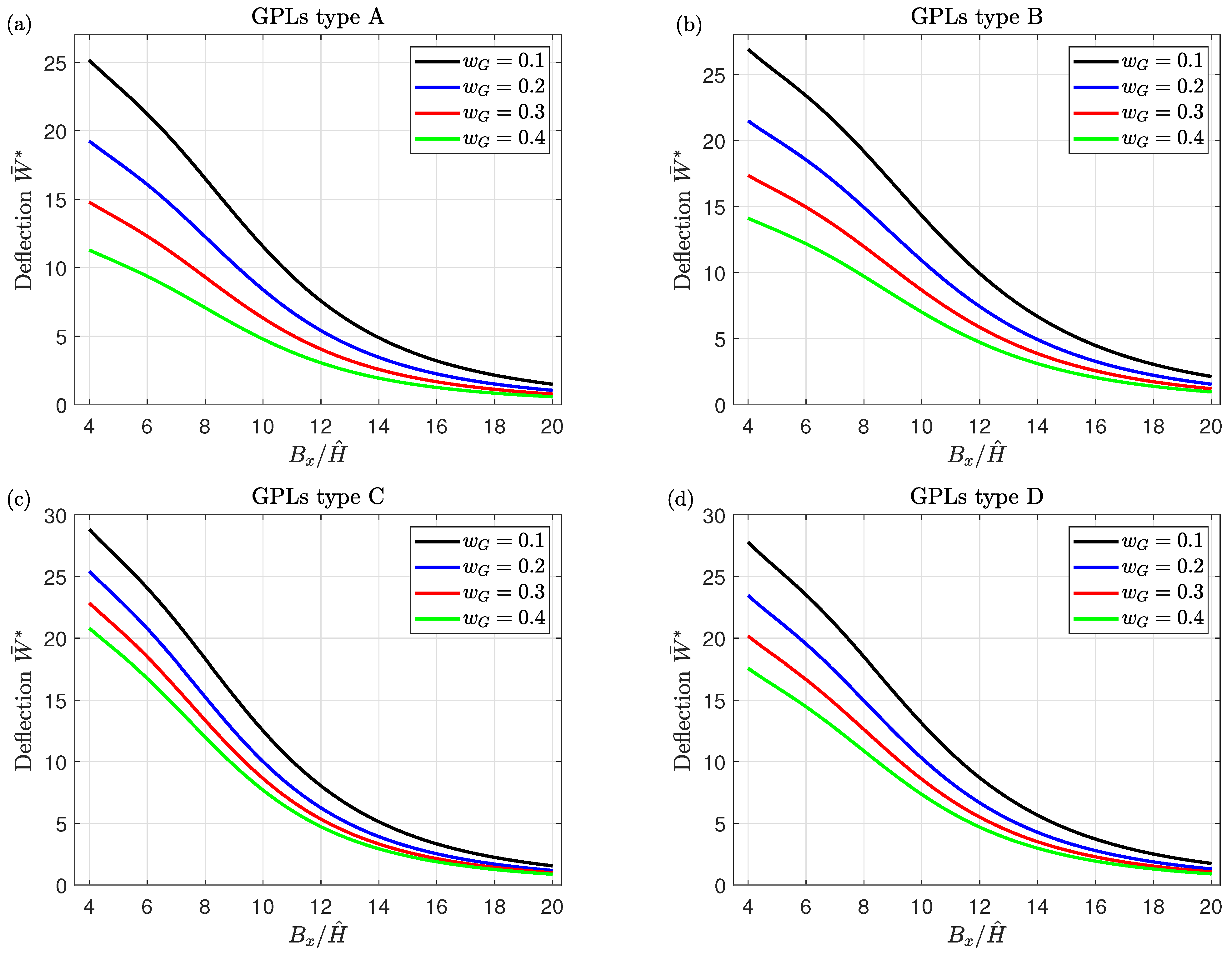
The effects of the GPLs weight fraction w G and the side-to-thickness ratio B x / H ^ on the non-dimensional central deflection W ¯ * of simply-supported FG piezoelectromagnetic nanocomposite honeycomb sandwich plates for various FGGP distribution types are illustrated in Figure 3. As it is discussed in the literature, irrespective of the the side-to-thickness ratio B x / H ^ , the increase in the percentage of graphene in the plates greatly boosts the mechanical properties of the plates and then strengthens their stiffness. For that reason, the obtained results of the central deflection W ¯ * suffer a great reduction due to the increments of the weight fraction w G .
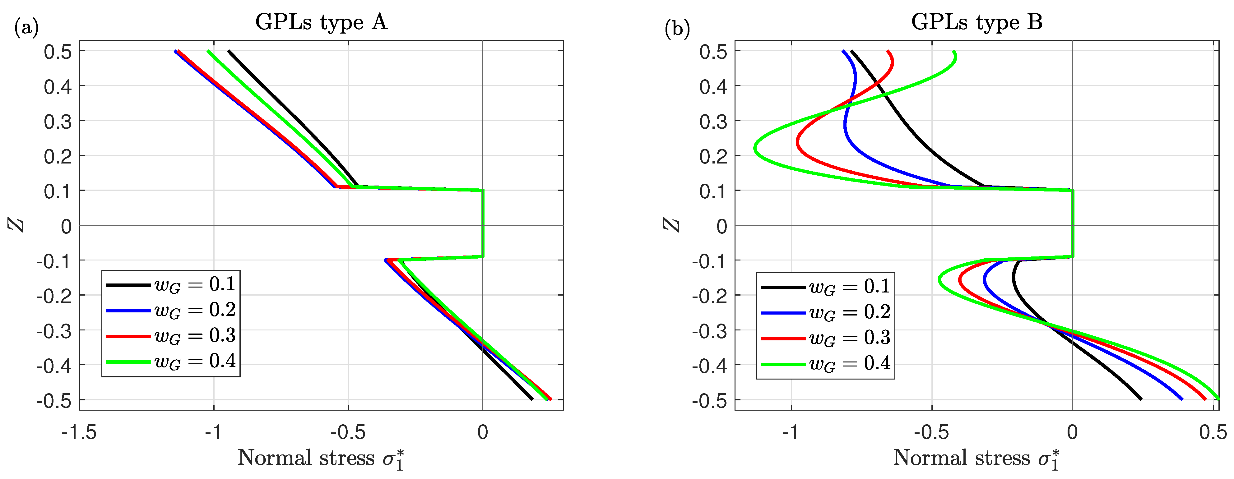
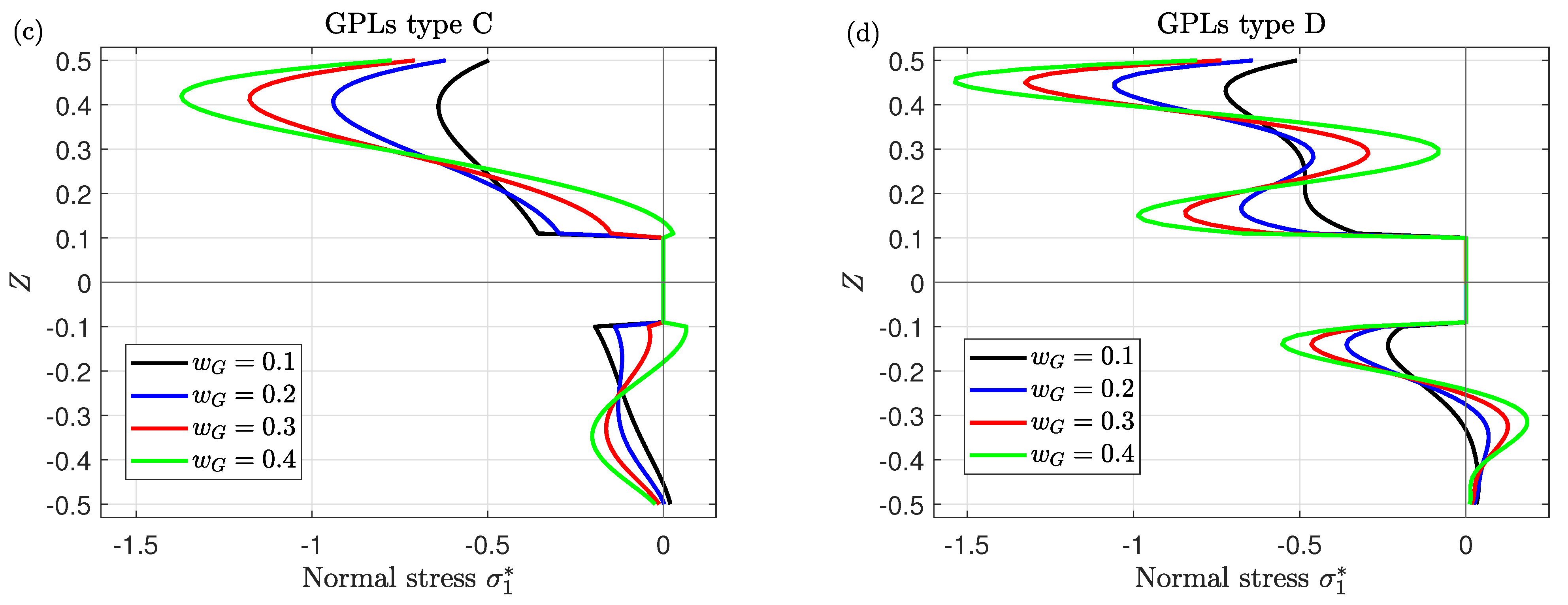
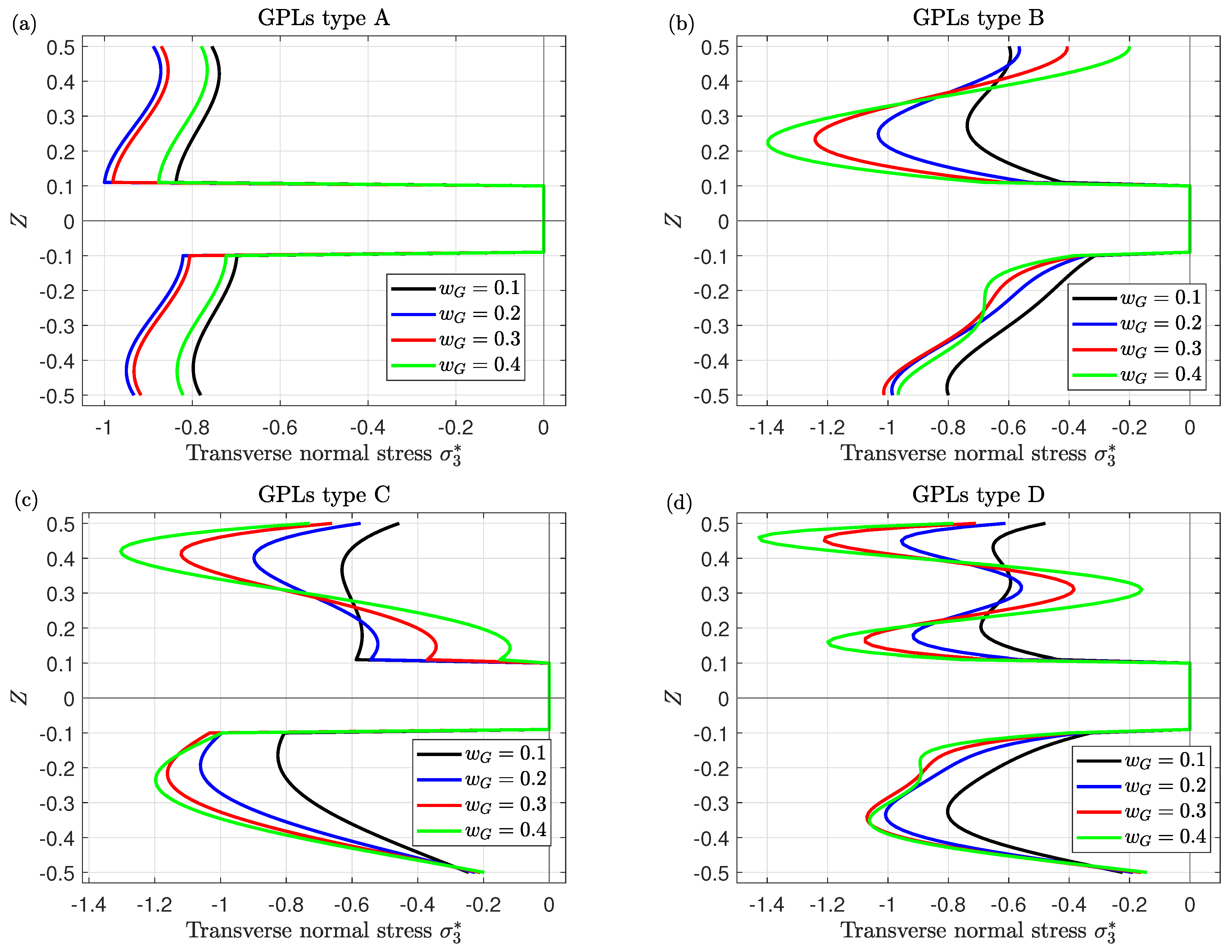
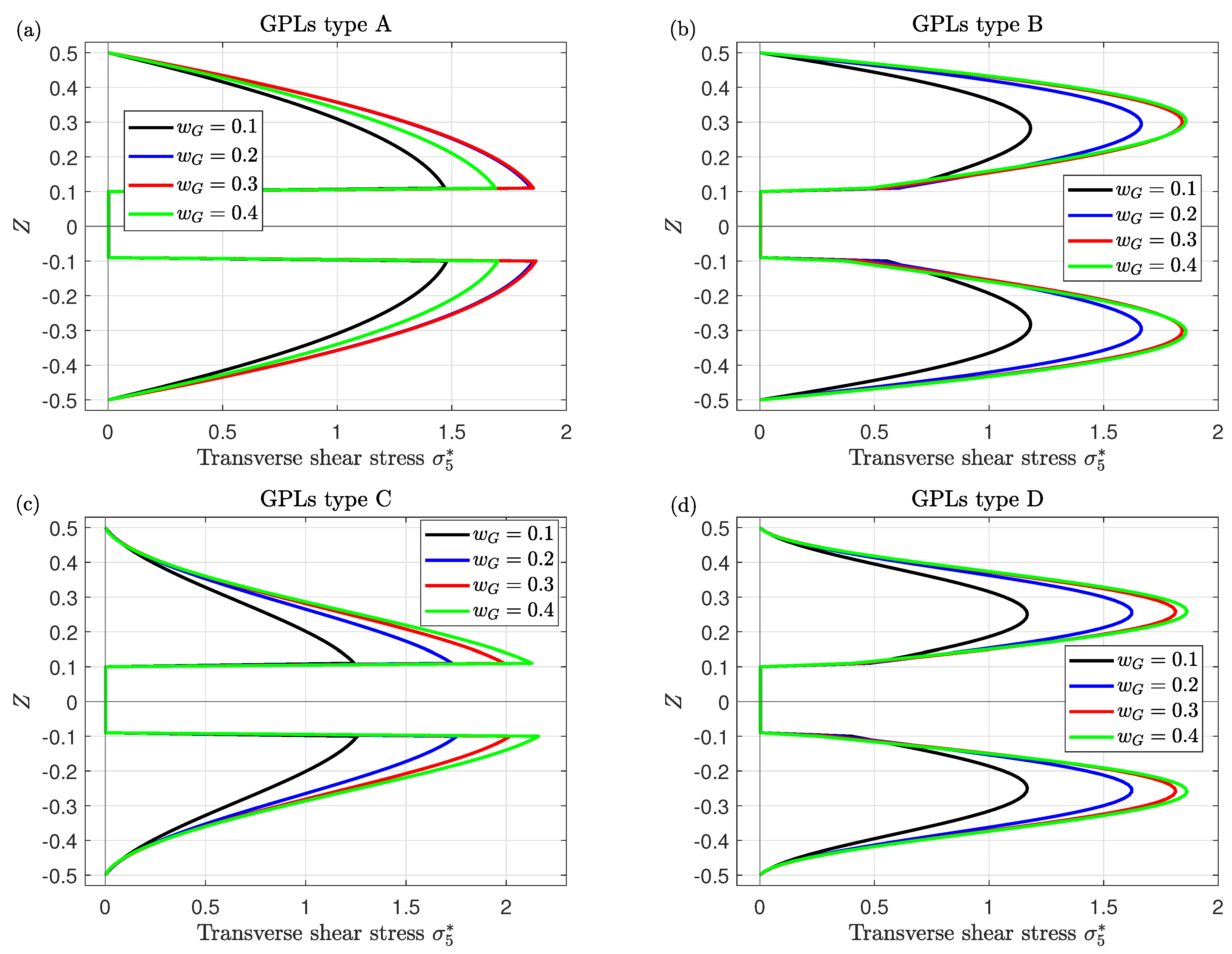
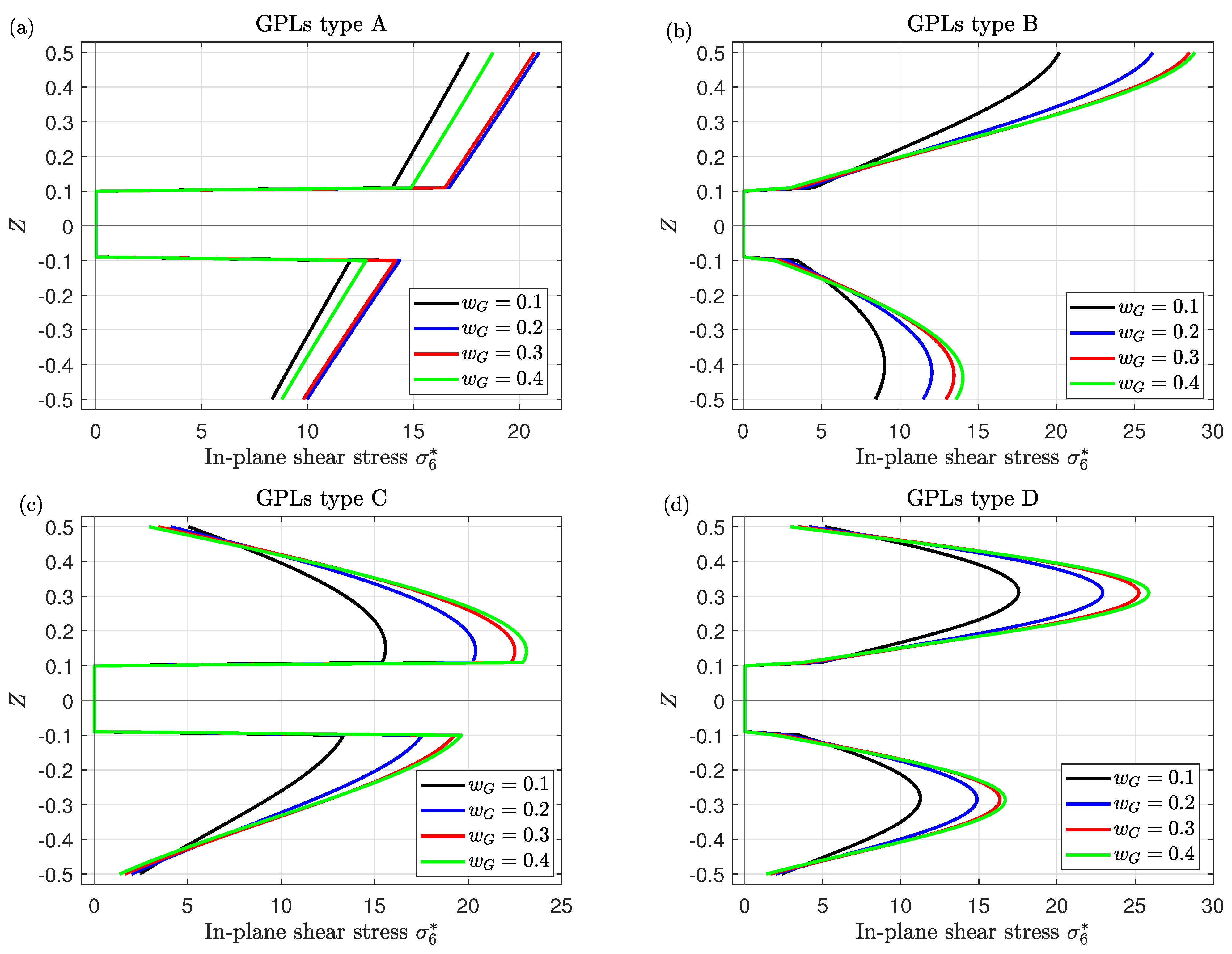
The variations of the normal stress σ 1 * , transverse normal stress σ 3 * , transverse shear stress σ 5 * and in-plane shear stress σ 6 * through the thickness of simply-supported FG piezoelectromagnetic nanocomposite honeycomb sandwich plates for various values of the GPLs weight fraction w G are investigated in Figure 4, Figure 5, Figure 6 and Figure 7, respectively, for different graphene distribution types. According to Figure 4, a gradual increment in the maximum stress σ 1 * occurs as the GPLs weight fraction w G increases. For more clarification, for GPLs type A, σ 1 * is linearly expanded throughout the thickness of the sandwich plate (see Figure 4a), illustrating the uniform dispersion of GPLs through the thickness of the plate. Furthermore, for all GPLs distribution types, the maximum stress σ 1 * occurs at the upper part of the plate, this is due to that the thermal and hygrothermal loads (temperature and moisture) have maximum values at the top faces of the plate. It is also noticed that the normal stress σ 1 * in the upper and lower layers of the plate of type B, C, and D has extremums at the large values of w G (as shown in Figure 4b–d) due to the sensitivity of graphene to temperature and moisture.
It is obvious from Figure 5 that the compressive stress σ 3 * occurs along the upper and lower layers of the plate. Moreover, the maximum transverse normal stress σ 3 * increases by increasing the GPLs weight fraction w G . It should be noted that the positive and negative signs represent tensile and compressive stresses, respectively.
Figure 6 displays the impact of the GPLs weight fraction w G on the transverse shear stress σ 5 * for all GPLs distribution types; the stress σ 5 * is parabolically changed. From Figure 6c, there is a monotoin increase in the maximum stress σ 5 * as the GPLs weight fraction w G increases. Whereas, in Figure 6a,b,d, the stress σ 5 * rises to reach its maximum value and then declines as w G increases. In addition, its maximums can be controlled by the GPLs distribution types. This demonstrates that an increment of the proportion of graphene in the structure of the plate enables the stress σ 5 * to behave oppositely, particularly considering the thermal load, due to that graphene possesses high thermal sensitivity.
Moreover, the maximum shear stress σ 6 * in the upper and lower layers of the plate has the same tendency with the variation of the GPLs weight fraction w G ; it is increased as w G increases for type B, C, and D (as shown in Figure 7). While, for type A, the in-plane shear stress σ 6 * is no longer increasing as w G increases and is linearly varied through the thickness of the plate. Since the shear stress σ 6 * significantly depends on the graphene distribution through the thickness, the maximum σ 6 * occurs at the upper and lower plate surfaces for type B, at the interfaces for type C, and at the mid-plane of the upper and lower layers for type D.
It is worthy of note that the stresses σ 1 * , σ 3 * , σ 5 * and σ 6 * are dependent considerably on the volume of the GPLs weight fraction w G .
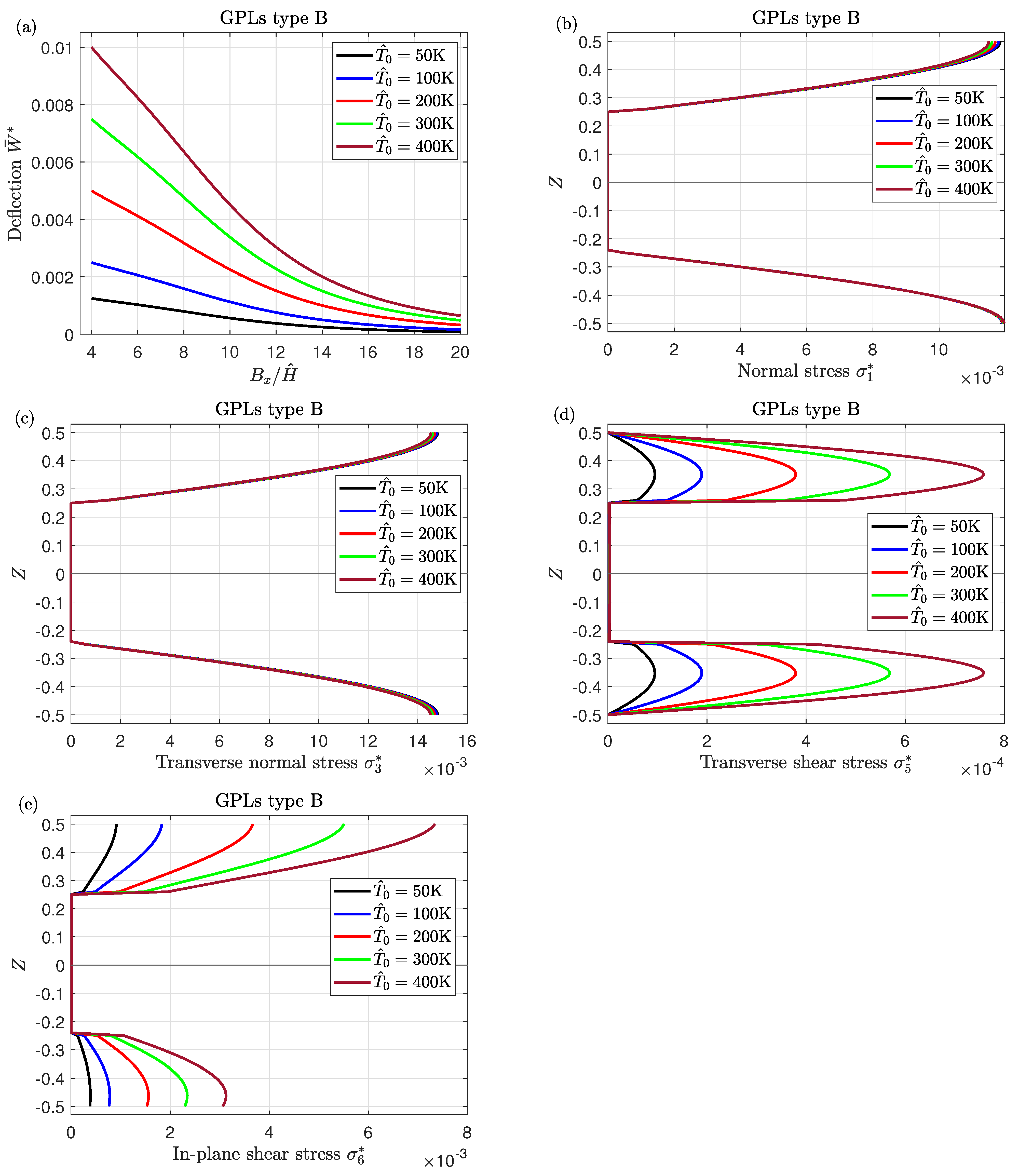
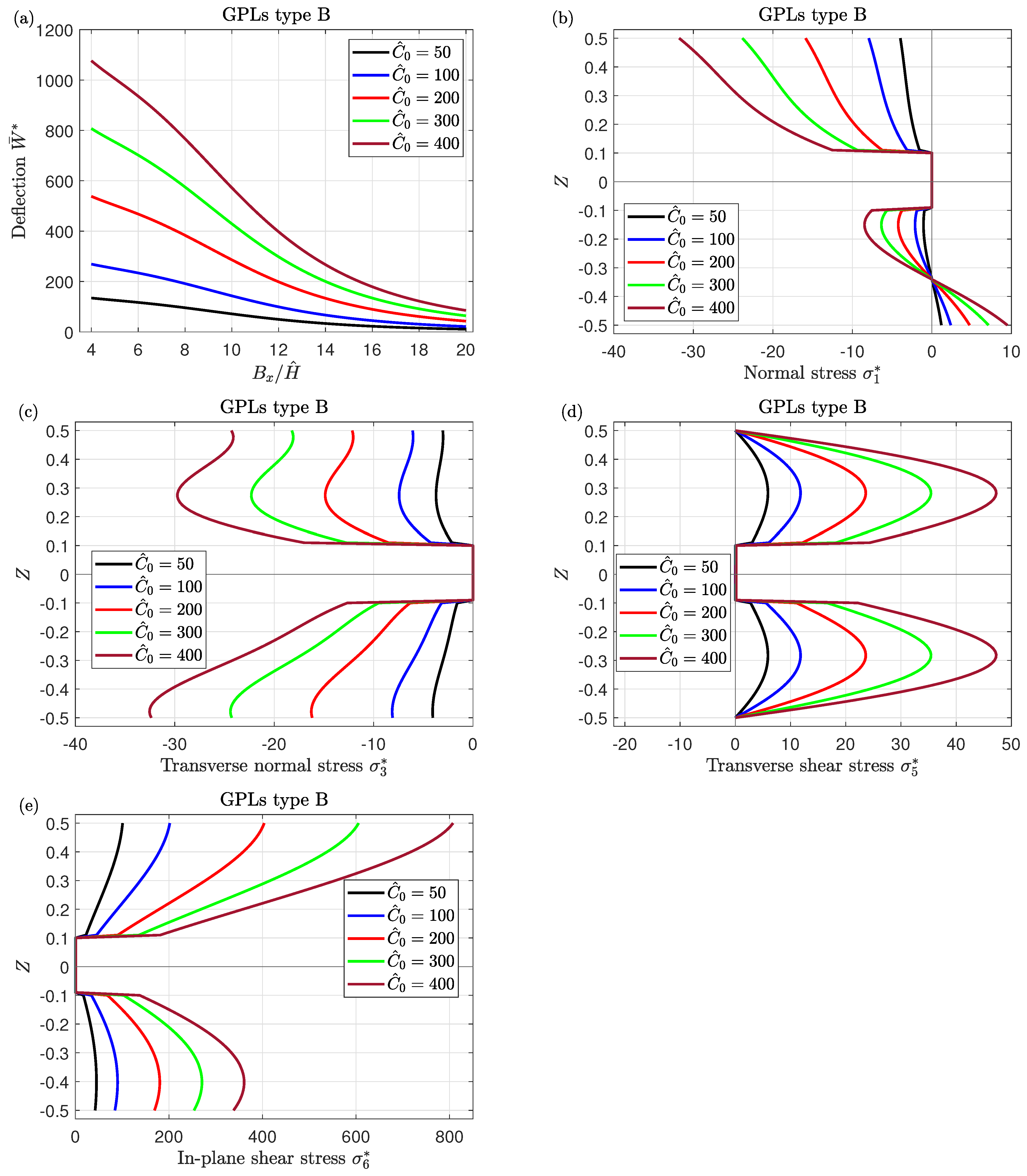
Figure 8 and Figure 9 illustrate the changes of the temperature parameter T ^ 0 and moisture parameter C ^ 0 on the central deflection W ¯ * , normal stress σ 1 * , transverse normal stress σ 3 * , transverse shear stress σ 5 * and in-plane shear stress σ 6 * of simply-supported FG piezoelectromagnetic nanocomposite honeycomb sandwich plates. As it is widely known, the rise in temperature and moisture leads to the weakening of the structure, consequently, severe increases in the deflection W ¯ * and the shear stresses σ 5 * and σ 6 * occur with increasing the temperature parameter T ^ 0 . From Figure 8b,c, σ 1 * and σ 3 * seem to be independent of changing the values of T ^ 0 . Furthermore, it is observed that the maximum stresses σ 1 * , σ 3 * , σ 5 * and σ 6 * have the same sense of the deflection with the variation of C ^ 0 ; they are increased with the rise in moisture parameter C ^ 0 (as shown in Figure 9).
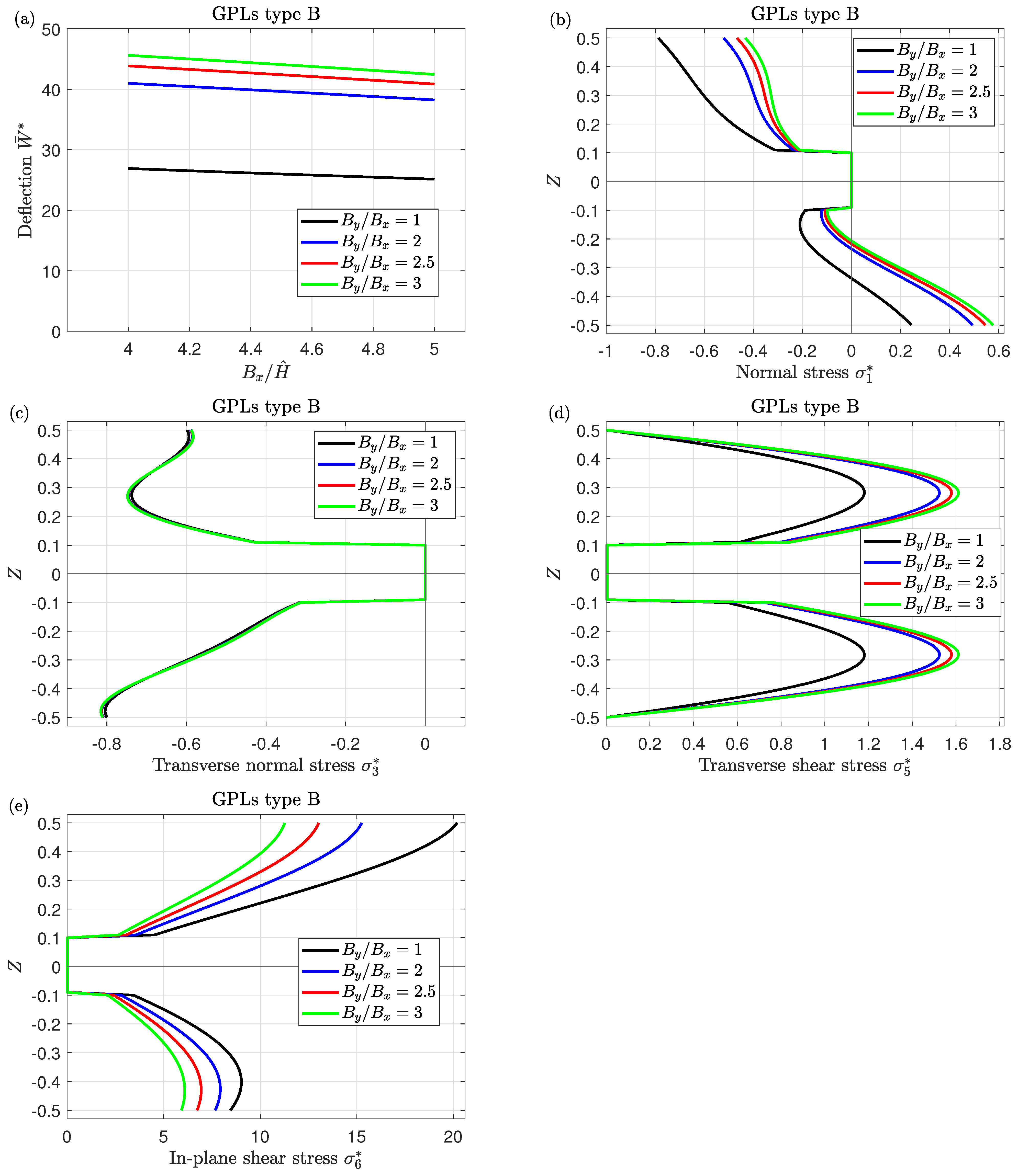
Figure 10 reveals the impact of the plate aspect ratio B y / B x on the central deflection W ¯ * , normal stress σ 1 * , transverse normal stress σ 3 * , transverse shear stress σ 5 * and in-plane shear stress σ 6 * of FG piezoelectromagnetic nanocomposite sandwich plates. It can be seen that the deflection W ¯ * is linearly varied with respect to the side-to-thickness ratio B x / H ^ for all values of B y / B x and it increases as the plate aspect ratio B y / B x increases and the side-to-thickness ratio B x / H ^ decreases. The normal stress σ 1 * in the upper surface decreases with increasing the aspect ratio B y / B x , while it has an opposite sense in the bottom surface. The transverse shear stress σ 5 * increases monotonically with increasing B y / B x , while this behaviour may be reversed for the in-plane shear stress σ 6 * . Moreover, the sensitivity of the transverse normal stress σ 3 * to variations of the plate aspect ratio B y / B x is hardly noticeable.
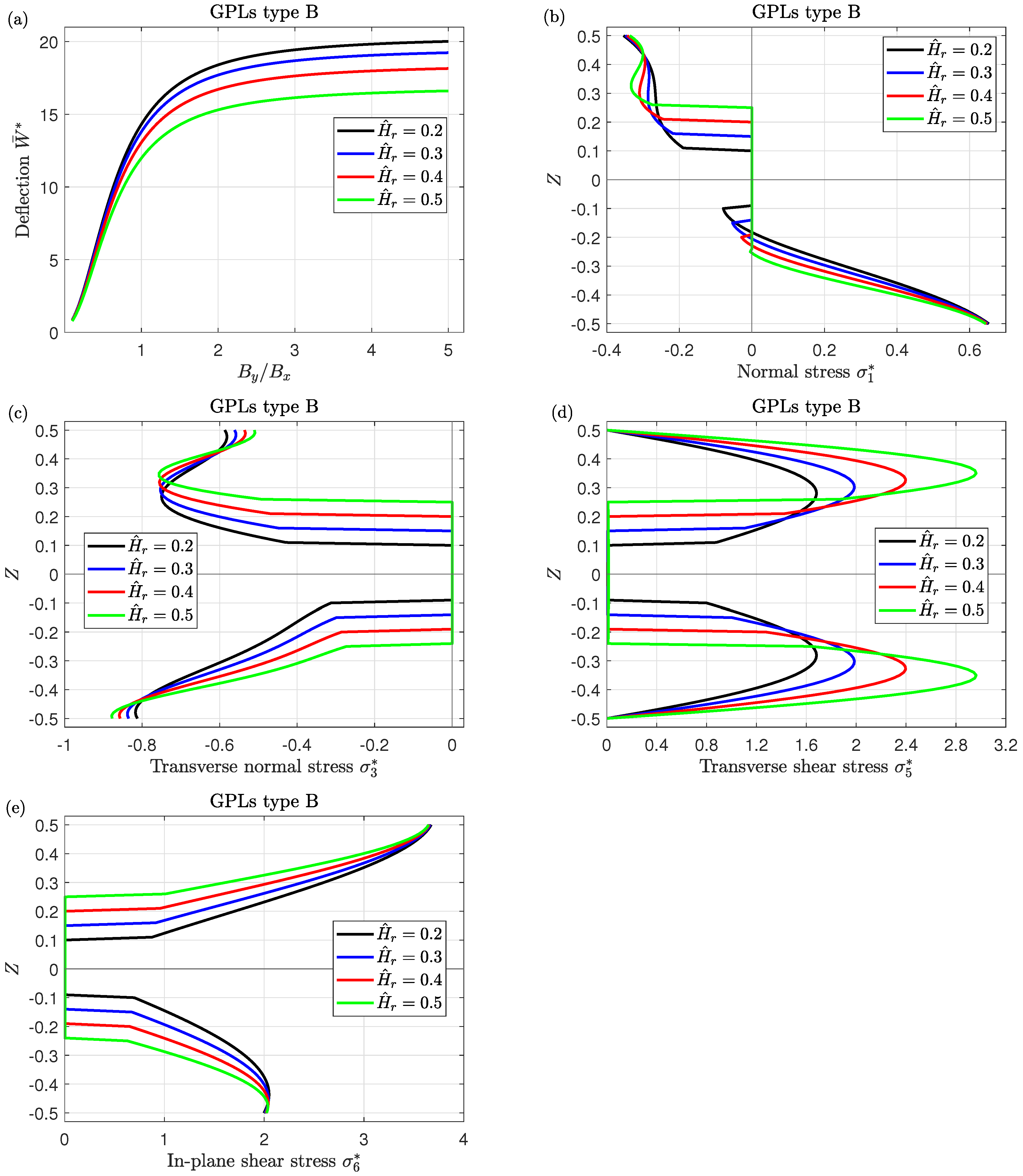
Figure 11 reveals the sensitivity of the deflection and stresses to the variation of the core-to-face thickness ratio H ^ r = H ^ c / H ^ of simply-supported FG piezoelectromagnetic nanocomposite honeycomb sandwich plates. Due to the low thermal and electrical conductivity of the honeycomb core, the rise of the core thickness leads to a decrease in the external electric impacts, therefore, it is clear that from Figure 11a the deflection W ¯ * decreases as the ratio H ^ r increases while it increases by increasing the aspect ratio B y / B x . Moreover, the tensile stress σ 1 * (occurs along the lower layer of the plate) declines by increasing H ^ r in the interval 0.5 Z 0.2 while the compressive stress σ 1 * (occurs along the upper layer of the plate) increases by increasing H ^ r in the interval 0.1 Z 0.5 . Furthermore, the compressive stress σ 3 * occurs along the upper and lower layers of the plate. The transverse normal stress σ 3 * generally rises with the increase of H ^ r in the upper layer of the plate while it decreases with the increase in H ^ r in the lower layer of the plate. It can be noted that the tensile in-plane shear stress σ 6 * decreases with the increase in H ^ r while this sense may be reversed for the transverse shear stress σ 5 * .
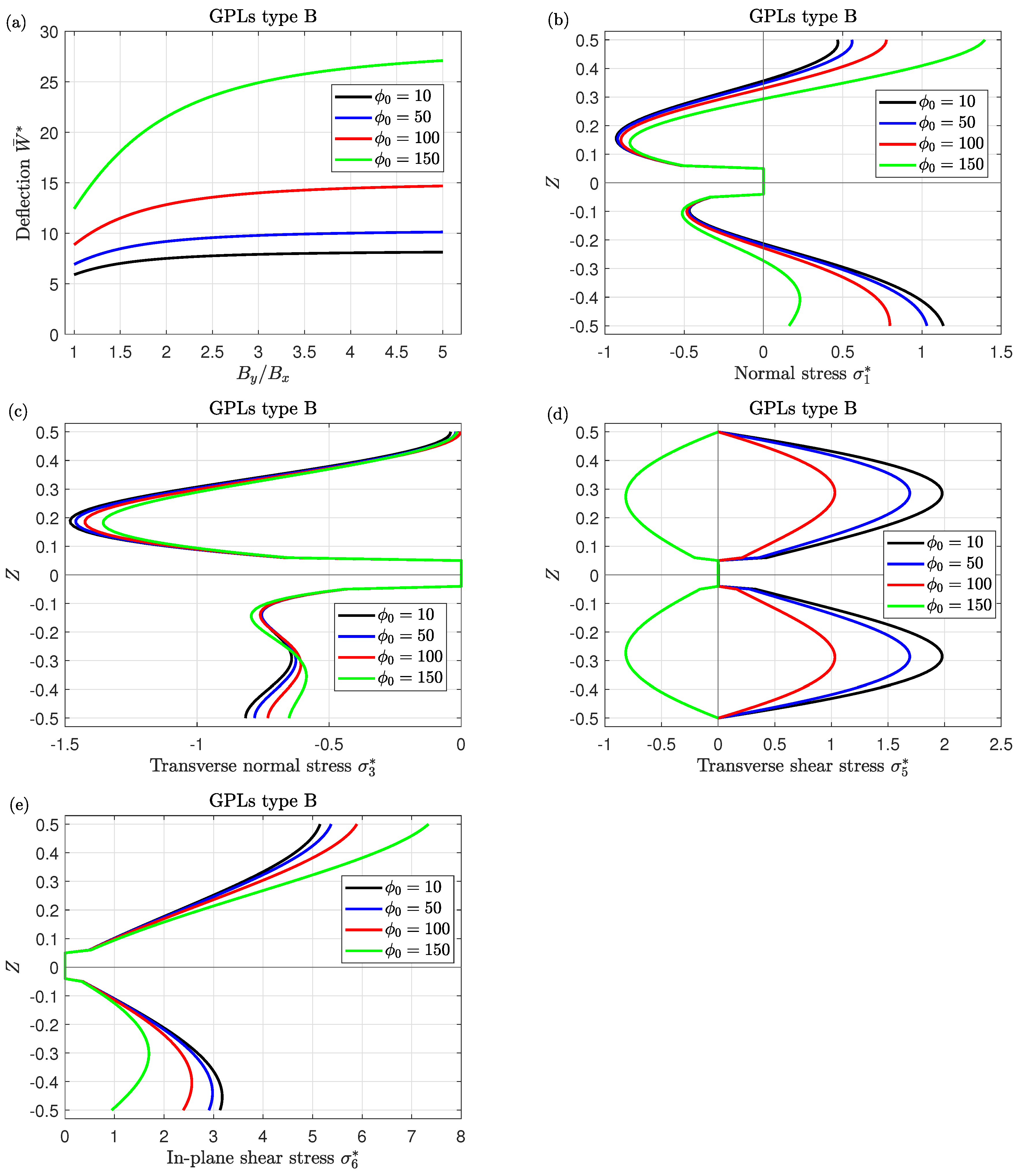
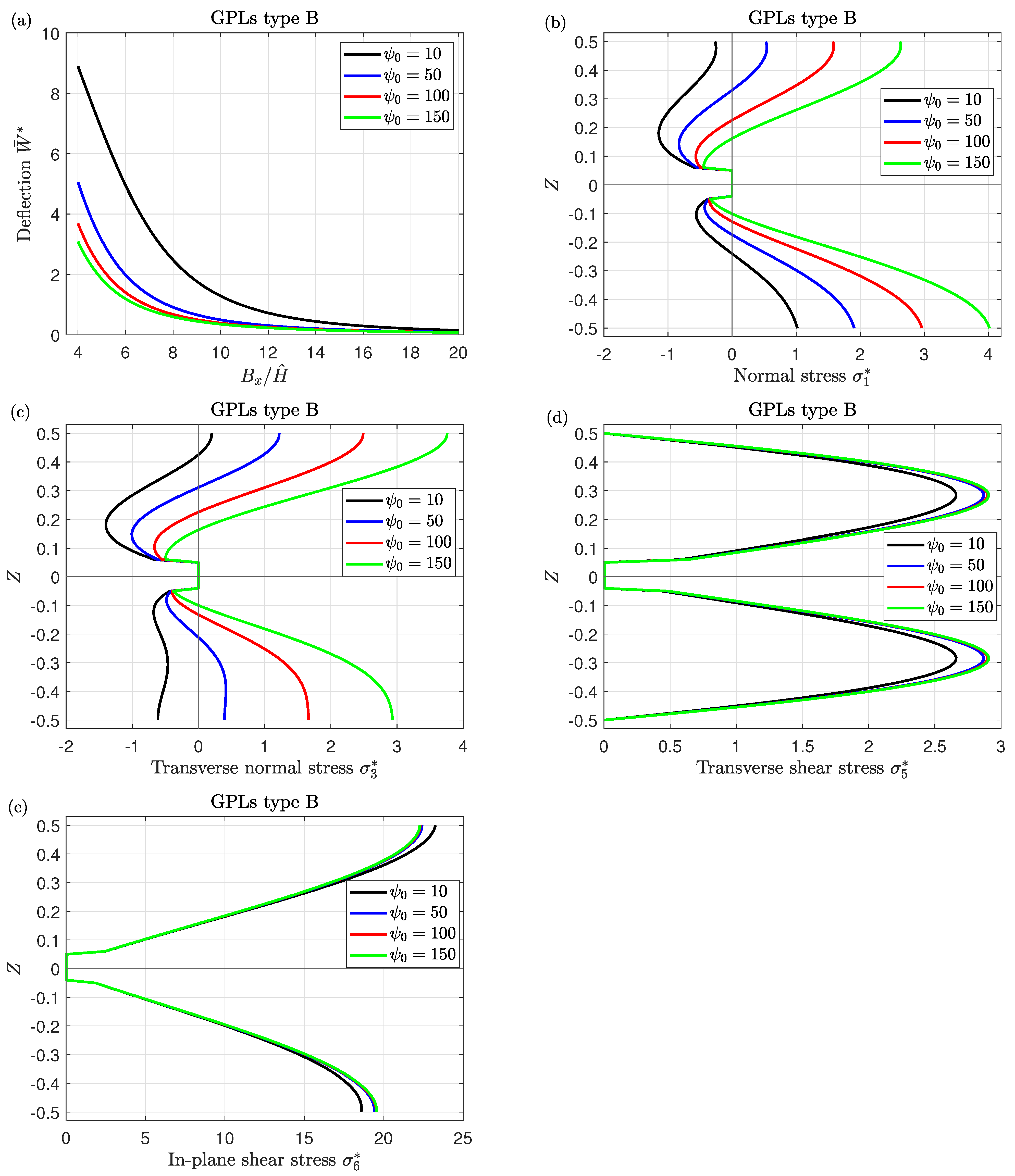
The investigation is also extended to assess the impacts of external electric and magnetic potentials on the obtained results, as shown in Figure 12 and Figure 13. It can be observed that the external electric potential ϕ 0 has a softening effect on the simply-supported FG piezoelectromagnetic nanocomposite honeycomb sandwich plates, whereas the external magnetic potential ψ 0 has a hardening effect. Accordingly, increasing the values of ϕ 0 and ψ 0 results in higher and lower deflection of the plate, as shown in Figure 12a and Figure 13a, respectively. Moreover, the transverse shear stress σ 5 * decreases with the increase in ϕ 0 (as seen in Figure 12d). Further, the normal stress σ 1 * and transverse normal stress σ 3 * increase monotonically with increasing ψ 0 , while this behavior may be less pronounced for the transverse shear stress σ 5 * and in-plane shear stress σ 6 * when changing ψ 0 .
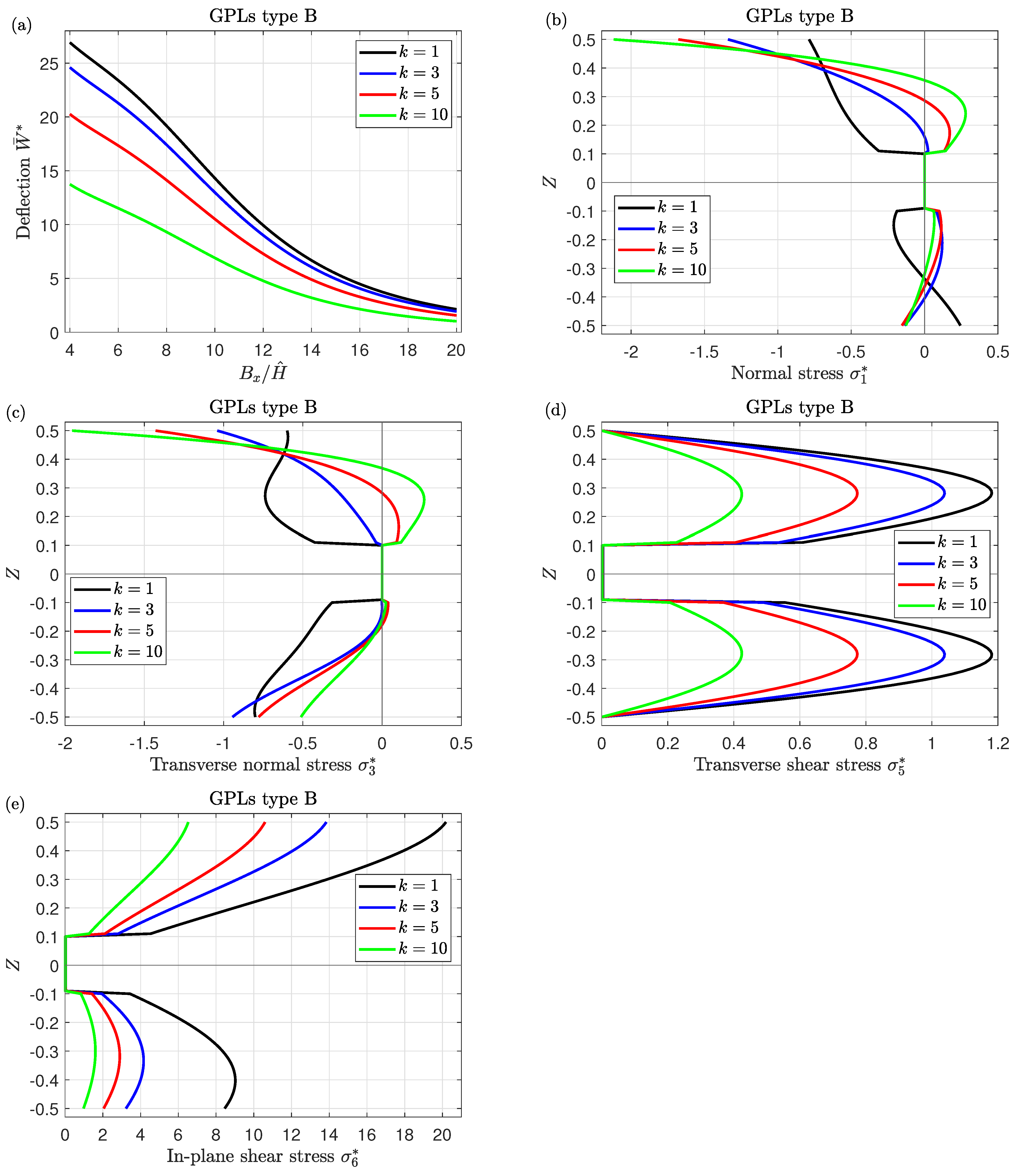
Figure 14 illustrates the influence of the thermal and moisture exponent k on the central deflection W ¯ * , normal stress σ 1 * , transverse normal stress σ 3 * , transverse shear stress σ 5 * and in-plane shear stress σ 6 * of simply-supported FG piezoelectromagnetic nanocomposite honeycomb sandwich plates. One can observe that a reduction occurs in deflection W ¯ * and shear stresses as k increase. While this sense is reversed for the maximum normal stresses σ 1 * and σ 3 * (as seen in Figure 14b,c).

7. Conclusions

For the first time, the static bending response of FG piezoelectromagnetic nanocomposite sandwich plates reinforced with GPLs containing hexagonal honeycomb cells as a middle layer under hygrothermal loads is presented. Moreover, based on a new quasi-3 dimensional higher-order shear deformation theory, the components of displacement are established. In particular, this theory comprises the effects of both normal deformations and effects of thickness stretching in FG piezoelectromagnetic nanocomposite honeycomb sandwich plates by a trigonometric variation of all displacements. In addition, the sandwich plates are exposed to external electric and magnetic fields as well as temperature and moisture concentrations. A Navier-type solution is employed to obtain the analytical solution of the governing equations of simply supported FGPZM plates. Numerical examples are presented to validate the accuracy of the present analysis. Other numerical investigations have been illustrated in tabular form and graphical one to describe the influences of the electric potential, magnetic potential, temperature, moisture, plate geometry (side-to-thickness, core-to-face thickness and plate aspect ratios), thermal and moisture exponent, GPLs weight fraction, and GPLs distribution type on the bending of the current plates. The concluding remarks can be summarized as follows:
  • The increment in graphene components enhances the strength of the sandwich nanocomposite piezoelectromagnetic plates leading to a reduction in the central deflection.
  • The variation of the stresses through the thickness of the plate significantly depends on GPLs distribution types.
  • While the moisture and temperature conditions weaken the plate stiffness, therefore, the central deflection and stresses rise as the moisture and temperature parameter increase; normal stresses appear to be independent of varying the temperature parameter.
  • The existence of the honeycomb core results in the plate being more resistant to the thermal condition and the external electric voltage due to the low thermal and electrical conductivity of the honeycomb cells. Subsequently, the central deflection decreases with increasing the thickness of the honeycomb core.
  • By varying the external electric and magnetic potentials, the deflection behavior of the sandwich structures can be managed. Increasing the electric and magnetic parameters leads to an increment and decrement in the deflection, respectively.
  • This investigation illustrates that the current study can produce very accurate results compared with other theories in literature and, therefore, deserves particular attention and additional execution by using numerical techniques.
  • The suggested model and our numerical findings could be very helpful for the design and production of many aerospace, automotive, or shipbuilding engineering applications. Honeycomb cells should be utilized in these applications due to their outstanding capacity to resist high pressures and stress despite their light structure.

Funding

This research received no external funding.

Data Availability Statement

Not applicable.

Conflicts of Interest

The author declares no conflict of interest.

References

  1. Gibson, L.J.; Ashby, M.F. Cellular Solids: Structure and Properties, 2nd ed.; Cambridge University Press: Cambridge, UK, 1997. [Google Scholar]
  2. Sobhy, M. Size-dependent hygro-thermal buckling of porous FGM sandwich microplates and microbeams using a novel four-variable shear deformation theory. Int. J. Appl. Mech. 2020, 12, 2050017. [Google Scholar] [CrossRef]
  3. Chen, A.; Davalos, J.F. A solution including skin effect for stiffness and stress field of sandwich honeycomb core. Int. J. Solids Struct. 2005, 42, 2711–2739. [Google Scholar] [CrossRef]
  4. Qing, T.D.; Zhi, C.Y. Wave propagation in sandwich panel with auxetic core. J. Solid Mech. 2010, 2, 393–402. [Google Scholar]
  5. Yu, S.D.; Cleghorn, W.L. Free flexural vibration analysis of symmetric honeycomb panels. J. Sound Vib. 2005, 284, 189–204. [Google Scholar] [CrossRef]
  6. Cong, P.H.; Khanh, N.D.; Khoa, N.D.; Duc, N.D. New approach to investigate nonlinear dynamic response of sandwich auxetic double curves shallow shells using TSDT. Compos. Struct. 2018, 185, 455–465. [Google Scholar] [CrossRef]
  7. Li, Y.Q.; Li, F.; He, Y.L. Geometrically nonlinear forced vibrations of the symmetric rectangular honeycomb sandwich panels with completed clamped supported boundaries. Compos. Struct. 2011, 93, 360–368. [Google Scholar] [CrossRef]
  8. Li, Y.; Zhou, M.; Wang, T.; Zhang, Y. Nonlinear primary resonance with internal resonances of the symmetric rectangular honeycomb sandwich panels with simply supported along all four edges. Thin-Walled Struct. 2020, 147, 106480. [Google Scholar] [CrossRef]
  9. Zhang, J.; Zhu, X.; Yang, X.; Zhang, W. Transient nonlinear responses of an auxetic honeycomb sandwich plate under impact loads. Inter. J. Impact Eng. 2019, 134, 103383. [Google Scholar] [CrossRef]
  10. Tornabene, F.; Viscoti, M.; Dimitri, R.; Aiello, M.A. Higher order formulations for doubly-curved shell structures with a honeycomb core. Thin-Walled Struct. 2021, 164, 107789. [Google Scholar] [CrossRef]
  11. Tan, P.; Tong, L. Modeling for the electro-magneto-thermo-elastic properties of piezoelectric-magnetic fiber reinforced composites. Compos. Part A Appl. Sci. Manuf. 2002, 33, 631–645. [Google Scholar] [CrossRef]
  12. Singh, S.; Singh, A.K.; Guha, S. Reflection of plane waves at the stress-free/rigid surface of a micro-mechanically modeled piezo-electro-magnetic fiber-reinforced half-space. Waves Random Complex Media 2022. [Google Scholar] [CrossRef]
  13. Sun, J.; Xu, X.; Lim, C.W.; Zhou, Z.; Xiao, S. Accurate thermo-electro-mechanical buckling of shear deformable piezoelectric fiber-reinforced composite cylindrical shells. Compos. Struct. 2016, 141, 221–231. [Google Scholar] [CrossRef]
  14. Zhu, S.; Tong, Z.; Sun, J.; Li, Q.; Zhou, Z.; Xu, X. Electro-thermo-mechanical post-buckling of piezoelectric functionally graded cylindrical shells. Appl. Math. Model. 2021, 98, 309–322. [Google Scholar] [CrossRef]
  15. Huang, X.; Zhi, C.; Lin, Y.; Bao, H.; Wu, G.; Jiang, P.; Mai, Y.W. Thermal conductivity of graphene-based polymer nanocomposites. Mater. Sci. Eng. R Rep. 2020, 142, 100577. [Google Scholar] [CrossRef]
  16. Potts, J.R.; Dreyer, D.R.; Bielawski, C.W.; Ruoff, R.S. Graphene-based polymer nanocomposites. Polymer 2011, 52, 5–25. [Google Scholar] [CrossRef]
  17. Alimirzaei, S.; Mohammadimehr, M.; Tounsi, A. Nonlinear analysis of viscoelastic micro-composite beam with geometrical imperfection using FEM: MSGT electro-magneto-elastic bending, buckling and vibration solutions. Struct. Eng. Mech. 2019, 71, 485–502. [Google Scholar]
  18. Song, M.; Yang, J.; Kitipornchai, S. Bending and buckling analyses of functionally graded polymer composite plates reinforced with graphene nanoplatelets. Compos. Part B Eng. 2018, 134, 106–113. [Google Scholar] [CrossRef]
  19. Li, K.; Wu, D.; Chen, X.; Cheng, J.; Liu, Z.; Gao, W.; Liu, M. Isogeometric analysis of functionally graded porous plates reinforced by graphene platelets. Compos. Struct. 2018, 204, 114–130. [Google Scholar] [CrossRef]
  20. Sahmani, S.; Aghdam, M.M. Nonlinear instability of axially loaded functionally graded multilayer graphene platelet-reinforced nanoshells based on nonlocal strain gradient elasticity theory. Int. J. Mech. Sci. 2017, 131, 95–106. [Google Scholar] [CrossRef]
  21. Sobhy, M. Buckling and vibration of FG graphene platelets/aluminum sandwich curved nanobeams considering the thickness stretching effect and exposed to a magnetic field. Results Phys. 2020, 16, 102865. [Google Scholar] [CrossRef]
  22. Thai, C.H.; Ferreira, A.J.M.; Tran, T.D.; Phung-Van, P. A size-dependent quasi-3D isogeometric model for functionally graded graphene platelet-reinforced composite microplates based on the modified couple stress theory. Compos. Struct. 2020, 234, 111695. [Google Scholar] [CrossRef]
  23. Al Mukahal, F.H.H.; Sobhy, M. Wave propagation and free vibration of FG graphene platelets sandwich curved beam with auxetic core resting on viscoelastic foundation via DQM. Arch. Civ. Mech. Eng. 2022, 22, 12. [Google Scholar] [CrossRef]
  24. Sobhy, M. Analytical buckling temperature prediction of FG piezoelectric sandwich plates with lightweight core. Mater. Res. Express 2021, 8, 095704. [Google Scholar] [CrossRef]
  25. Abazid, M.A.; Sobhy, M.; Zenkour, A.M. Wave propagation in FG porous GPLs-reinforced nanoplates under in-plane mechanical load and Lorentz magnetic force via a new quasi 3D plate theory. Mech. Based Des. Struct. Mach. 2022, 50, 1831–1850. [Google Scholar] [CrossRef]
  26. Abazid, M.A. 2D magnetic field effect on the thermal buckling of metal foam nanoplates reinforced with FG-GPLs lying on pasternak foundation in humid environment. Eur. Phys. J. Plus 2020, 135, 910. [Google Scholar] [CrossRef]
  27. Sobhy, M. 3-D elasticity numerical solution for magneto-hygrothermal bending of FG graphene/metal circular and annular plates on an elastic medium. Eur. J. Mech.-A/Solids 2021, 88, 104265. [Google Scholar] [CrossRef]
  28. Sobhy, M.; Abazid, M.A.; Al Mukahal, F.H.H. Electro-thermal buckling of FG graphene platelets-strengthened piezoelectric beams under humid conditions. Adv. Mech. Eng. 2022, 14, 1–12. [Google Scholar] [CrossRef]
  29. Al Mukahal, F.H.H.; Abazid, M.A.; Sobhy, M. Investigating Electromechanical Buckling Response of FG-GPL-Reinforced Piezoelectric Doubly Curved Shallow Shells Embedded in an Elastic Substrate. Materials 2023, 16, 2975. [Google Scholar] [CrossRef]
  30. Zhou, Z.; Wang, Y.; Zhang, S.; Dimitri, R.; Tornabene, F.; Asemi, K. Numerical Study on the Buckling Behavior of FG Porous Spherical Caps Reinforced by Graphene Platelets. Nanomaterials 2023, 13, 1205. [Google Scholar] [CrossRef]
  31. Quang Hung, T.; Duc, D.M.; Minh Tu, T. Static bending mesh-free analysis of smart piezoelectric porous beam reinforced with graphene platelets. Proc. Inst. Mech. Eng. Part C J. Mech. Eng. Sci. 2023, 237, 1595–1612. [Google Scholar] [CrossRef]
  32. Xu, K.; Wang, K.; Zhao, W.; Bao, W.; Liu, E.; Ren, Y.; Wang, M.; Fu, Y.; Zeng, J.; Li, Z.; et al. The positive piezoconductive effect in graphene. Nat. Commun. 2015, 6, 8119. [Google Scholar] [CrossRef] [PubMed]
  33. Abolhasani, M.M.; Shirvanimoghaddam, K.; Naebe, M. PVDF/graphene composite nanofibers with enhanced piezoelectric performance for development of robust nanogenerators. Compos. Sci. Technol. 2017, 138, 49–56. [Google Scholar] [CrossRef]
  34. Mao, J.J.; Lu, H.M.; Zhang, W.; Lai, S.K. Vibrations of graphene nanoplatelet reinforced functionally gradient piezoelectric composite microplate based on nonlocal theory. Compos. Struct. 2020, 236, 111813. [Google Scholar] [CrossRef]
  35. Sobhy, M.; Al Mukahal, F.H.H. Analysis of Electromagnetic Effects on Vibration of Functionally Graded GPLs Reinforced Piezoelectromagnetic Plates on an Elastic Substrate. Crystals 2022, 12, 487. [Google Scholar] [CrossRef]
  36. Sobhy, M.; Al Mukahal, F.H. Wave Dispersion Analysis of Functionally Graded GPLs-Reinforced Sandwich Piezoelectromagnetic Plates with a Honeycomb Core. Mathematics 2022, 10, 3207. [Google Scholar] [CrossRef]
  37. Khorasani, M.; Soleimani-Javid, Z.; Arshid, E.; Amir, S.; Civalek, Ö. Vibration analysis of graphene nanoplatelets’ reinforced composite plates integrated by piezo-electromagnetic patches on the piezo-electromagnetic media. Waves Random Complex Media 2021. [Google Scholar] [CrossRef]
  38. Alazwari, M.A.; Zenkour, A.M.; Sobhy, M. Hygrothermal Buckling of Smart Graphene/Piezoelectric Nanocomposite Circular Plates on an Elastic Substrate via DQM. Mathematics 2022, 10, 2638. [Google Scholar] [CrossRef]
  39. Sobhy, M.; Al Mukahal, F.H.H. Magnetic control of vibrational behavior of smart FG sandwich plates with honeycomb core via a quasi-3D plate theory. Adv. Eng. Mater. 2023. [Google Scholar] [CrossRef]
  40. Mahesh, V. Nonlinear damping of auxetic sandwich plates with functionally graded magneto-electro-elastic facings under multiphysics loads and electromagnetic circuits. Compos. Struct. 2022, 290, 115523. [Google Scholar] [CrossRef]
  41. Belardi, V.G.; Fanelli, P.; Vivio, F. Application of the Ritz method for the bending and stress analysis of thin rectilinear orthotropic composite sector plates. Thin-Walled Struct. 2023, 183, 110374. [Google Scholar] [CrossRef]
  42. Singh, A.; Karathanasopoulos, N. Three-dimensional analytical elasticity solution for the mechanical analysis of arbitrarily-supported, cross and angle-ply composite plates under patch loads. Compos. Struct. 2023, 310, 116752. [Google Scholar] [CrossRef]
  43. Attar, F.; Khordad, R.; Zarifi, A.; Modabberasl, A. Application of nonlocal modified couple stress to study of functionally graded piezoelectric plates. Phys. B Condens. Matter 2021, 600, 412623. [Google Scholar] [CrossRef]
  44. Li, J.; Xue, Y.; Li, F.; Narita, Y. Active vibration control of functionally graded piezoelectric material plate. Compos. Struct. 2019, 207, 509–518. [Google Scholar] [CrossRef]
  45. Sheng, G.G.; Wang, X. Thermoelastic vibration and buckling analysis of functionally graded piezoelectric cylindrical shells. Appl. Math. Model. 2010, 34, 2630–2643. [Google Scholar] [CrossRef]
  46. Sobhy, M.; Radwan, A.F. An axial magnetic field effect on frequency analysis of rotating sandwich cylindrical shells with FG graphene/AL face sheets and honeycomb core. Int. J. Appl. Mech. 2022, 14, 2250074. [Google Scholar] [CrossRef]
  47. Abdollahi, M.; Saidi, A.R.; Mohammadi, M. Buckling analysis of thick functionally graded piezoelectric plates based on the higher-order shear and normal deformable theory. Acta Mech. 2015, 226, 2497–2510. [Google Scholar] [CrossRef]
  48. Sobhy, M.; Abazid, M.A. Mechanical and thermal buckling of FG-GPLs sandwich plates with negative Poisson’s ratio honeycomb core on an elastic substrate. Eur. Phys. J. Plus 2022, 137, 93. [Google Scholar] [CrossRef]
  49. Zaitoun, M.W.; Chikh, A.; Tounsi, A.; Al-Osta, M.A.; Sharif, A.; Al-Dulaijan, S.U.; Al-Zahrani, M.M. Influence of the visco-Pasternak foundation parameters on the buckling behavior of a sandwich functional graded ceramic–metal plate in a hygrothermal environment. Thin-Walled Struct. 2022, 170, 108549. [Google Scholar] [CrossRef]
  50. Hebali, H.; Chikh, A.; Bousahla, A.A.; Bourada, F.; Tounsi, A.; Benrahou, K.H.; Hussain, M.; Tounsi, A. Effect of the variable visco-Pasternak foundations on the bending and dynamic behaviors of FG plates using integral HSDT model. Arch. Appl. Mech. 2022, 83, 177–191. [Google Scholar]
  51. Bakoura, A.; Bourada, F.; Bousahla, A.A.; Tounsi, A.; Benrahou, K.H.; Tounsi, A.; Al-Zahrani, M.M.; Mahmoud, S.R. Buckling analysis of functionally graded plates using HSDT in conjunction with the stress function method. Comput. Concr. Int. J. 2021, 27, 73–83. [Google Scholar]
  52. Tahir, S.I.; Tounsi, A.; Chikh, A.; Al-Osta, M.A.; Al-Dulaijan, S.U.; Al-Zahrani, M.M. The effect of three-variable viscoelastic foundation on the wave propagation in functionally graded sandwich plates via a simple quasi-3D HSDT. Steel Compos. Struct. 2022, 42, 501. [Google Scholar]
  53. Bouafia, K.; Selim, M.M.; Bourada, F.; Bousahla, A.A.; Bourada, M.; Tounsi, A.; Adda Bedia, E.A.; Tounsi, A. Bending and free vibration characteristics of various compositions of FG plates on elastic foundation via quasi 3D HSDT model. Steel Compos. Struct. 2021, 41, 487–503. [Google Scholar]
  54. Kouider, D.; Kaci, A.; Selim, M.M.; Bousahla, A.A.; Bourada, F.; Tounsi, A.; Tounsi, A.; Tounsi, A.; Hussain, M. An original four-variable quasi-3D shear deformation theory for the static and free vibration analysis of new type of sandwich plates with both FG face sheets and FGM hard core. Steel Compos. Struct. 2021, 41, 167–191. [Google Scholar]
  55. Hachemi, H.; Bousahla, A.A.; Kaci, A.; Bourada, F.; Tounsi, A.; Benrahou, K.H.; Tounsi, A.; Al-Zahrani, M.M.; Mahmoud, S.R. Bending analysis of functionally graded plates using a new refined quasi-3D shear deformation theory and the concept of the neutral surface position. Steel Compos. Struct. Int. J. 2021, 39, 51–64. [Google Scholar]
  56. Sobhy, M.; Alsaleh, F. Nonlinear bending of FG metal/graphene sandwich microplates with metal foam core resting on nonlinear elastic foundations via a new plate theory. Mech. Based Des. Struct. Mach. 2023; in press. [Google Scholar]
  57. Shimpi, R.P. Refined plate theory and its variants. AIAA J. 2002, 40, 137–146. [Google Scholar] [CrossRef]
  58. Zamani, M.H.; Heidari-Rarani, M.; Torabi, K. A novel graded auxetic honeycomb core model for sandwich structures with increasing natural frequencies. J. Sandw. Struct. Mater. 2022, 24, 1313–1339. [Google Scholar] [CrossRef]
  59. Cong, P.H.; Duc, N.D. Nonlinear dynamic analysis of porous eccentrically stiffened double curved shallow auxetic shells in thermal environments. Thin-Walled Struct. 2021, 163, 107748. [Google Scholar] [CrossRef]
  60. Ke, L.L.; Wang, Y.S.; Yang, J.; Kitipornchai, S. Free vibration of size-dependent magneto-electro-elastic nanoplates based on the nonlocal theory. Acta Mech. Sin. 2014, 30, 516–525. [Google Scholar] [CrossRef]
  61. Arefi, M.; Zenkour, A.M. Free vibration analysis of a three-layered microbeam based on strain gradient theory and three-unknown shear and normal deformation theory. Steel Compos. Struct. Int. J. 2018, 26, 421–437. [Google Scholar]
  62. Arshid, H.; Khorasani, M.; Soleimani-Javid, Z.; Dimitri, R.; Tornabene, F. Quasi-3D hyperbolic shear deformation theory for the free vibration study of honeycomb microplates with graphene nanoplatelets-reinforced epoxy skins. Molecules 2020, 25, 5085. [Google Scholar] [CrossRef] [PubMed]
  63. Hebali, H.; Tounsi, A.; Houari, M.S.A.; Bessaim, A.; Bedia, E.A.A. New quasi-3D hyperbolic shear deformation theory for the static and free vibration analysis of functionally graded plates. J. Eng. Mech. 2014, 140, 374–383. [Google Scholar] [CrossRef]
  64. Alsebai, F.; Al Mukahal, F.H.; Sobhy, M. Semi-analytical solution for thermo-piezoelectric bending of FG porous plates reinforced with graphene platelets. Mathematics 2022, 10, 4104. [Google Scholar] [CrossRef]
  65. Abazid, M.A.; Sobhy, M. Thermo-electro-mechanical bending of FG piezoelectric microplates on Pasternak foundation based on a four-variable plate model and the modified couple stress theory. Microsyst. Technol. 2018, 24, 1227–1245. [Google Scholar] [CrossRef]
  66. Thai, H.T.; Kim, S.E. A size-dependent functionally graded Reddy plate model based on a modified couple stress theory. Compos. Part B Eng. 2013, 45, 1636–1645. [Google Scholar] [CrossRef]
  67. Thai, H.T.; Choi, D.H. A refined plate theory for functionally graded plates resting on elastic foundation. Compos. Sci. Technol. 2011, 71, 1850–1858. [Google Scholar] [CrossRef]
Figure 1. Configuration model of an FGPZMs sandwich plate with a honeycomb core, subjected to applied temperature and moisture.
Mathematics 11 02046 g001
Figure 2. The geometric model of the cell of honeycomb core.
Mathematics 11 02046 g002
Figure 3. Non-dimensional central deflection W ¯ * of simply-supported FG piezoelectromagnetic nanocomposite honeycomb sandwich plates versus the side-to-thickness ratio B x / H ^ for various values of the GPLs weight fraction w G for different graphene distribution types (a) type A, (b) type B, (c) type C, and (d) type D.
Mathematics 11 02046 g003
Figure 4. Non-dimensional normal stress σ 1 * through the thickness of simply-supported FG piezoelectromagnetic nanocomposite honeycomb sandwich plates for various values of the GPLs weight fraction w G and for different graphene distribution types (a) type A, (b) type B, (c) type C, and (d) type D.
Mathematics 11 02046 g004aMathematics 11 02046 g004b
Figure 5. Non-dimensional transverse normal stress σ 3 * through the thickness of simply-supported FG piezoelectromagnetic nanocomposite honeycomb sandwich plates for various values of the GPLs weight fraction w G and for different graphene distribution types (a) type A, (b) type B, (c) type C, and (d) type D.
Mathematics 11 02046 g005
Figure 6. Non-dimensional transverse shear stress σ 5 * through the thickness of simply-supported FG piezoelectromagnetic nanocomposite honeycomb sandwich plates for various values of the GPLs weight fraction w G and for different graphene distribution types (a) type A, (b) type B, (c) type C, and (d) type D.
Mathematics 11 02046 g006
Figure 7. Non-dimensional in-plane shear stress σ 6 * through the thickness of simply-supported FG piezoelectromagnetic nanocomposite honeycomb sandwich plates for various values of the GPLs weight fraction w G and for different graphene distribution types (a) type A, (b) type B, (c) type C, and (d) type D.
Mathematics 11 02046 g007
Figure 8. Effect of the temperature parameter T ^ 0 on the (a) central deflection W ¯ * , (b) normal stress σ 1 * , (c) transverse normal stress σ 3 * , (d) transverse shear stress σ 5 * , and (e) in-plane shear stress σ 6 * of simply-supported FG piezoelectromagnetic nanocomposite honeycomb sandwich plates.
Mathematics 11 02046 g008
Figure 9. Effect of the moisture parameter C ^ 0 on the (a) central deflection W ¯ * , (b) normal stress σ 1 * , (c) transverse normal stress σ 3 * , (d) transverse shear stress σ 5 * , and (e) in-plane shear stress σ 6 * of simply-supported FG piezoelectromagnetic nanocomposite honeycomb sandwich plates.
Mathematics 11 02046 g009
Figure 10. Effect of the plate aspect ratio B y / B x on the (a) central deflection W ¯ * , (b) normal stress σ 1 * , (c) transverse normal stress σ 3 * , (d) transverse shear stress σ 5 * , and (e) in-plane shear stress σ 6 * of simply-supported FG piezoelectromagnetic nanocomposite honeycomb sandwich plates.
Mathematics 11 02046 g010
Figure 11. Effect of the core-to-face thickness ratio H ^ r on the (a) central deflection W ¯ * , (b) normal stress σ 1 * , (c) transverse normal stress σ 3 * , (d) transverse shear stress σ 5 * , and (e) in-plane shear stress σ 6 * of simply-supported FG piezoelectromagnetic nanocomposite honeycomb sandwich plates.
Mathematics 11 02046 g011
Figure 12. Effect of the external applied electric potential ϕ 0 on the (a) central deflection W ¯ * , (b) normal stress σ 1 * , (c) transverse normal stress σ 3 * , (d) transverse shear stress σ 5 * , and (e) in-plane shear stress σ 6 * of simply-supported FG piezoelectromagnetic nanocomposite honeycomb sandwich plates.
Mathematics 11 02046 g012
Figure 13. Effect of the external applied magnetic potential ψ 0 on the (a) central deflection W ¯ * , (b) normal stress σ 1 * , (c) transverse normal stress σ 3 * , (d) transverse shear stress σ 5 * , and (e) in-plane shear stress σ 6 * of simply-supported FG piezoelectromagnetic nanocomposite honeycomb sandwich plates.
Mathematics 11 02046 g013
Figure 14. Effect of the thermal and moisture exponent k on the (a) central deflection W ¯ * , (b) normal stress σ 1 * , (c) transverse normal stress σ 3 * , (d) transverse shear stress σ 5 * , and (e) in-plane shear stress σ 6 * of simply-supported FG piezoelectromagnetic nanocomposite honeycomb sandwich plates.
Mathematics 11 02046 g014
Table 1. Material properties of the piezoelectromagnetic matrix and GPLs [60].
MaterialsPiezoelectromagneticGPLs
E(GPa)1.41010
ν 0.290.186
ρ (g/cm 3 )1.921.06
β ( 10 6 K 1 )3.065
κ ¯ (wt.% H 2 O ) 1 0.440.00026
α 31 = α 32 ( 10 3 C / m 2 )−2.2−2.2 ξ 0
α 33 ( 10 3 C / m 2 )9.39.3 ξ 0
α 15 = α 24 ( 10 3 C / m 2 )5.85.8 ξ 0
χ 31 = χ 32   ( NA 1 m 1 ) 290.1290.1 ξ 0
χ 33   ( NA 1 m 1 ) 349.9349.9 ξ 0
χ 15 = χ 24   ( NA 1 m 1 ) 275275 ξ 0
P 11 = P 22   ( 10 9 CV 1 m 1 ) 5.645.64 ξ 0
P 33 ( 10 9   ( CV 1 m 1 ) 6.356.35 ξ 0
S 11 = S 22   ( 10 12 Ns V 1 C 1 ) 5.3675.367 ξ 0
S 33   ( 10 12 Ns V 1 C 1 ) 2737.52737.5 ξ 0
R 11 = R 22   ( 10 16 Ns 2 C 2 ) −297−297 ξ 0
R 33   ( 10 16 Ns 2 C 2 ) 83.583.5 ξ 0
Table 2. Comparison of the central deflection ( W ¯ * = 10 W ¯ E C H ^ 3 / ( q 0 B x 4 ) ) of an FG simply supported aluminum/alumina square plate.
B x / H ^ ε 3 Source κ = 0 κ = 1 κ = 2 κ = 5 κ = 10
5 Ref. [66]0.34330.66880.86711.08851.2276
=0Present0.34330.66880.86711.08891.2277
≠0Present0.32350.61890.79561.00371.1420
10 Ref. [66]0.29610.58900.75730.91141.0087
=0Present0.29610.58900.75730.91151.0088
≠0Present0.29060.56350.71470.86400.9693
20Ref. [66]0.28420.56890.72980.86690.9538
=0Present0.28420.56890.72980.86690.9538
≠0Present0.28280.55020.69530.83010.9274
100Ref. [66]0.28040.56250.72090.85270.9362
=0Present0.28040.56250.72090.85270.9362
≠0Present0.28030.54610.68910.81930.9141
Table 3. Comparison of the central deflection ( W ¯ * = 10 W ¯ E C H ^ 3 / ( q 0 B x 4 ) ) and stresses σ 1 * = σ 1 H ^ / ( q 0 B x ) , σ 2 * = σ 2 H ^ / ( q 0 B x ) and σ 6 * = σ 1 H ^ / ( q 0 B x ) of an FG simply supported aluminum/alumina square plate ( B x / H ^ = 5 ).
k ε 3 Source W ¯ * σ 1 * σ 2 * σ 6 *
0 Ref. [67]0.29611.99431.31240.7067
=0Present0.29611.99451.31230.7066
≠0Present0.29142.02691.31260.7009
1 Ref. [67]0.58903.08501.48980.6111
=0Present0.58903.08541.48970.6111
≠0Present0.56473.11211.44810.5659
2 Ref. [67]0.75733.60671.39600.5442
=0Present0.75733.60721.39590.5442
≠0Present0.71663.63991.34190.4943
3 Ref. [67]0.83753.87091.27560.5526
=0Present0.83753.87151.27550.5526
≠0Present0.79173.90151.21770.5005
4 Ref. [67]0.88154.06551.17940.5669
=0Present0.88164.06621.17920.5669
≠0Present0.83584.09151.12200.5146
5 Ref. [67]0.91144.24471.10410.5757
=0Present0.91154.24551.10390.5756
≠0Present0.86734.26651.04950.5246
6 Ref. [67]0.93514.42011.04280.5806
=0Present0.93524.42091.04260.5805
≠0Present0.89314.43870.99190.5313
7 Ref. [67]0.95584.59280.99150.5836
=0Present0.95594.59370.99130.5836
≠0Present0.91584.60930.94420.5363
8 Ref. [67]0.97464.76190.94770.5858
=0Present0.97474.7270.94750.5858
≠0Present0.93644.77710.90410.5405
9 Ref. [67]0.99214.92610.91030.5878
=0Present0.99224.92690.91010.5877
≠0Present0.95564.94070.87000.5443
Table 4. Comparison of the central deflection W ^ and stresses σ ^ 1 , and σ ^ 5 of an FG simply supported piezoelectric plate resting on elastic foundations.
J e J s Ref. [65]Present
W ^ σ ^ 1 σ ^ 5 W ^ σ ^ 1 σ ^ 5
0053.61227−0.699810.0243153.68555−0.698260.08231
1030.113240.430180.2812230.119300.430950.31548
2020.592100.843830.4231320.587180.843380.44638
3015.512501.042980.5225415.505851.042570.53920
50044.74203−0.229530.0907544.78091−0.227970.14095
1026.850120.599600.3067526.849630.600070.33799
2018.916410.929090.4368218.909520.928870.45845
3014.497211.093700.5311814.489831.093160.54681
100038.199670.114830.1404438.217630.116180.18480
1024.155750.738330.3281724.150610.738530.35688
2017.459931.002560.4489217.451551.002160.46912
3013.588371.138710.5390413.580431.138050.55374
150033.179360.376940.1791833.183900.377980.21897
1021.894750.853710.3464521.886270.853650.37300
2016.182871.066390.4597116.173371.065820.47864
3012.770391.178860.5462312.762031.178080.56009
Disclaimer/Publisher’s Note: The statements, opinions and data contained in all publications are solely those of the individual author(s) and contributor(s) and not of MDPI and/or the editor(s). MDPI and/or the editor(s) disclaim responsibility for any injury to people or property resulting from any ideas, methods, instructions or products referred to in the content.