Article

Analytical Modelling of an Active Vibration Absorber for a Beam

Engineering Department, Pontificia Universidad Catolica del Peru, San Miguel 15088, Peru
*
Author to whom correspondence should be addressed.
Mathematics 2023, 11(9), 2009; https://doi.org/10.3390/math11092009
Submission received: 25 February 2023 / Revised: 28 March 2023 / Accepted: 28 March 2023 / Published: 24 April 2023
(This article belongs to the Special Issue Applied Mathematics to Mechanisms and Machines II)

Abstract

:
Attenuation of mechanical vibrations is an ongoing field of research in engineering aiming at reducing damage and improving performance in the presence of dynamical forces. Different alternatives have been proposed over time; the active vibration absorber can be highlighted as an alternative which can absorb the vibration from system in real time. In this study, an active vibration absorber was modelled as an electromechanical device. It was applied to a cantilever beam, mathematically modelled as a continuous beam. A set of differential equations representing the dynamical behaviour of the cantilever beam and active vibration absorber was obtained and it was simulated in Matlab Simulink®. Results indicated that the active vibration absorber is able to significantly reduce the vibration amplitudes of a system, especially in resonance conditions. The analytical model and procedure developed here can easily spread to any more complex system.

1. Introduction

Mechanical vibrations are manifested in almost any human activity. In the engineering field, they appear in structures, machinery, piping systems and other areas as a consequence of dynamic forces over time. High vibration amplitudes affect negatively the performance of a system and damage its structure, components and other systems which are connected in some way. Vibrations are usually monitored in specific locations which provide useful information in order to prevent catastrophic failures and correct them in an initial stage [1,2]. In this sense, attenuation of vibration amplitudes has been a continuous field of research for engineering. The dynamic vibration absorber invented by Frahm in 1909 [3] can be highlighted as a mechanical device capable of changing the dynamical characteristics of an existing system. It consists of a secondary system tuned to a specific excitation frequency in order to produce an opposite equal force to the perturbation in a primary system over time [4].
The main disadvantage of the passive vibration absorber is it is not effective if the perturbation changes its frequency since the vibration absorber parameters are not able to change. On the other hand, the active vibration absorber compensates for this characteristic since it is able to tune its parameters for different requirements. In active absorption, an actuator component is added to the vibration absorber in order to tune it to any excitation frequency in real time. Control strategies of this active component have been developed, especially in active control for structural engineering [5,6]. One of the first active vibration absorbers was designed in order to reduce the vibration amplitudes of a tall building, modelled as discrete masses [7,8]. Chang and Yang proposed an active mass damper for a structure modelled as discrete masses, but actuator dynamics was not considered [9]. Kwak, Yang and Shin proposed a semi active absorber, where the active component was controlled by a correlation with the current magnitude through a solenoid [10]. Yu, Thenozhi and Li studied the active vibration absorber implemented in a discrete structure model with PD/PID control of the active force using position over time as feedback [11]. Yang, Shin, Lee, Kim and Kwak used an acceleration feedback, since it was the simplest variable which can be measured directly by accelerometers [12]. Chang developed an LQR control of an AMD with an acceleration feedback for a scaled bridge modelled as a rigid body [13]. Ramesh and Narayanan presented a better accurate structure model of a beam based on the finite element method (FEM) [14]. Cao and Li proposed a new control algorithm, with a better response than LQR under same conditions, based on the calculation of the optimal gains in order to obtain the minimum variance of the displacement response over time [15]. Zhou and Li applied an active tuned mass damper (AMTD) with an LQR control algorithm to a tall building represented as an FEM model calibrated by its dynamical response measurement [16]. In these studies, primary systems were modelled as discrete systems. However, real systems are more complex than a discrete model as well as their dynamical behaviours. Different control strategies and feedback variables have been implemented, where PD/PID control algorithms can be highlighted as the standard industrial controllers due to its simplicity and the theory being well known [11]. Other current strategies consist of adding devices for damping. Some authors proposed structural damping for controlling the vibration amplitude [17]. Active damping was also proposed based on magnetorheological damper [18]. Linear motion is not the only consequence of vibration, torsional vibration is also a field of research. An electromagnetic torsion active vibration absorber has been proposed [19]. Applications of an active vibration absorber are not limited to structural and mechanical engineering, The concept has been extended to the medical field in order to reduce the vibration amplitude of tremor in human arms [20]. Passive vibration absorber has been effective for this application [21,22,23]. The main advantage for patients is that it is a non-invasive device. However, it is not able to tune its parameters for different requirements as an active absorber.
In this paper, an active vibration absorber (AVA) is modelled as an electromechanical device. A cantilever beam is chosen as a primary system since it can be used to represent different structures. This was represented as a continuous model which is the most accurate model of a real body since it is based on a strong formulation of the differential equations. The main advantage of a continuous model is that it allows to quantify the influence of the AVA when it is placed in different positions along the structure. The PD control algorithm is used for controlling the active force. The developed procedure is not limited to structures, it can be applied to different systems by coupling the AVA equations.

2. Materials and Methods

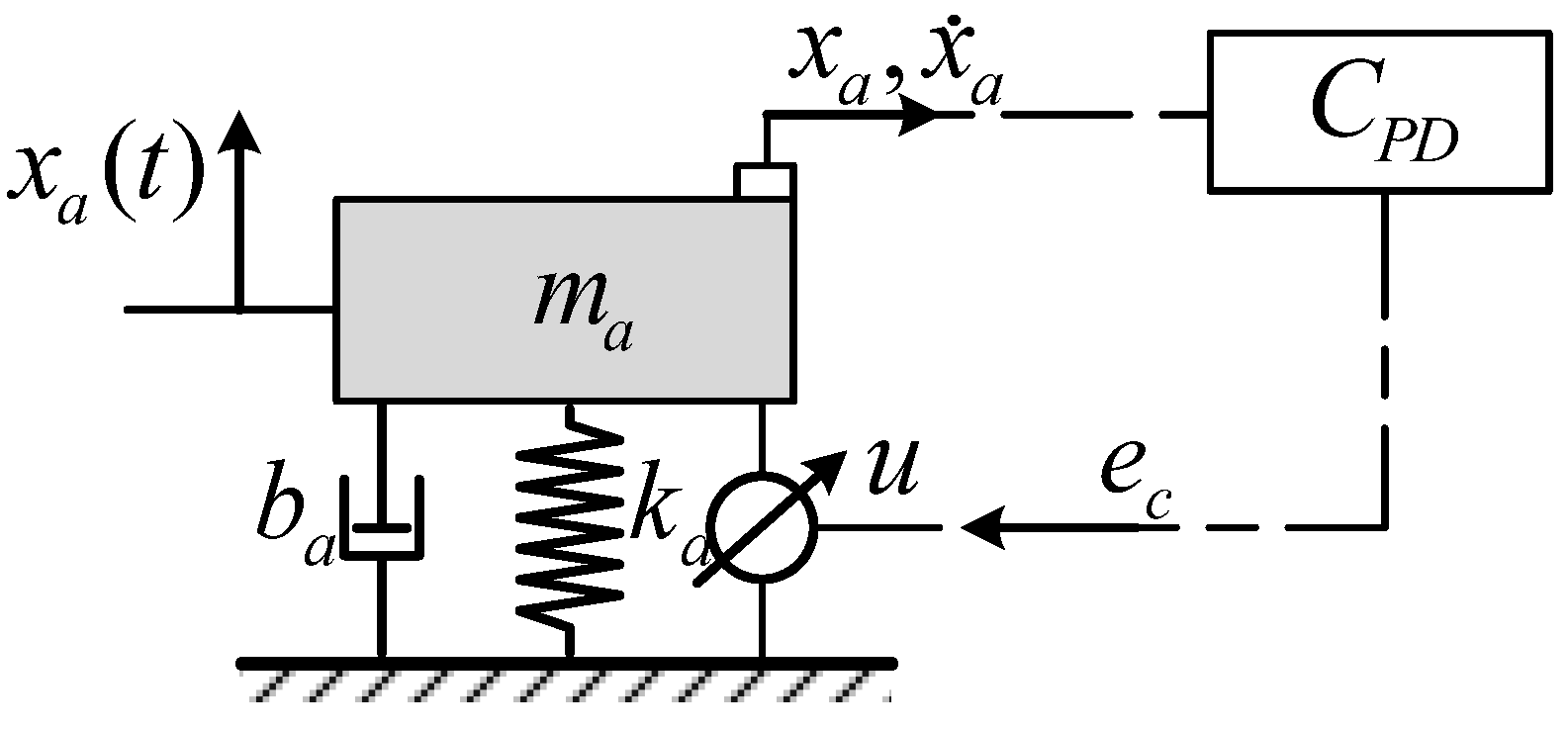
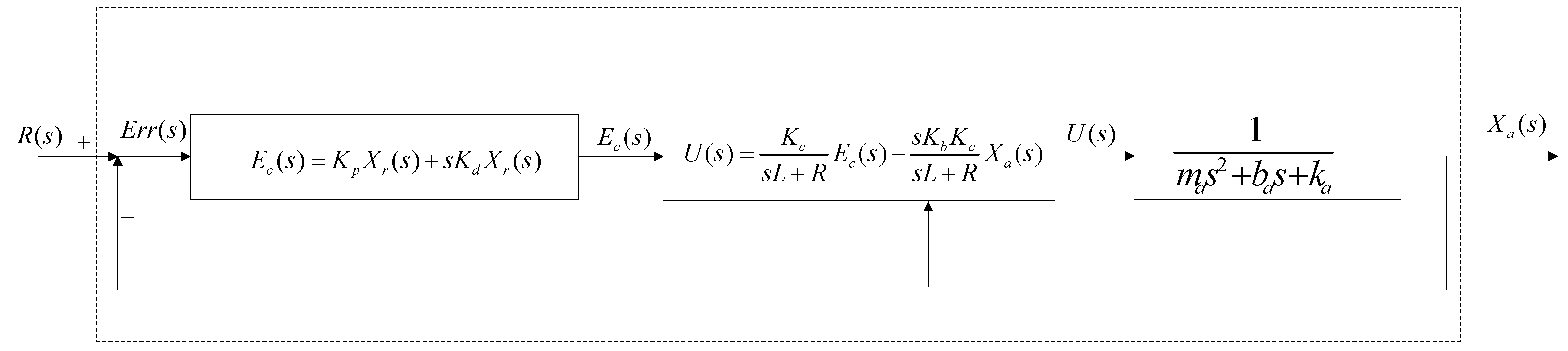
2.1. Active Vibration Absorber Model

The active vibration absorber can be modelled as a 1-DOF system, Figure 1. It consists of a mass m a , a damper that is represented by a damping coefficient b a , stiffness k a and an external active force produced by an actuator u. The magnitude and direction of the active force is calculated in order to tune this system to any excitation frequency.
By using Newton’s 2nd Law, the equation of motion for this vibration absorber is given by (1).
m a x ¨ a + b a x ˙ a + k a x a = u
The actuator is modelled as an electromagnetic actuator. Thus, the dynamic behaviour is obtained from its geometric and electromagnetic characteristics according to the modelling presented in [24,25]. It can be simplified as an equivalent electrical LR circuit given by (2), where L is inductance, R is resistance, I is current and e c is excitation voltage. K b x ˙ a is a voltage induced by the relative movement in the presence of current through a solenoid [26], where K b is the actuator constant.
L i ˙ + R i + K b x ˙ a = e c
The interaction between an electromagnetic field and the current through a circuit of the electromagnetic actuator produces the active force over time according to Lorentz’s Law, (3), where u is the active force and K c is an actuator constant.
u = K c i
According to the vibration absorption theory, the natural frequency of the decoupled system must be equal to the excitation frequency of the primary system. The same working concept is used to tune the active vibration absorber. In this sense, a PD control is able to modify the real part as well as the imaginary part of the poles of its characteristic equation in order to locate these poles in the imaginary axis with a frequency equal to the excitation frequency. The PD control of the electromagnetic actuator voltage was proposed in [26] and it has the following form (4), where K p and K d are the PD gains for the position and velocity feedback.
e c = K p x a + K d x ˙ a
Using Laplace transform in Equations (1)–(3) and ordering, Equations (5) and (6) in the Laplace domain are obtained.
X a ( s ) = K c m a s 2 + b a s + k a s L + R + K b K c s E ( s )
E c ( s ) = K p X a ( s ) + s K d X a ( s )
Solving the characteristic equation of the system, the PD gains which tune the natural frequency of the active vibration absorber to the excitation frequency ω c are given by (7) and (8) according to [26].
K p = Re L s + R m a s 2 + c a s + k a K b K c s K c s = ω c i
K d = 1 ω c Im L s + R m a s 2 + c a s + k a K b K c s K c s = ω c i
The equations above in the Laplace domain of the active vibration absorber response are represented as a control diagram with the position and velocity of the absorber feedback, Figure 2.

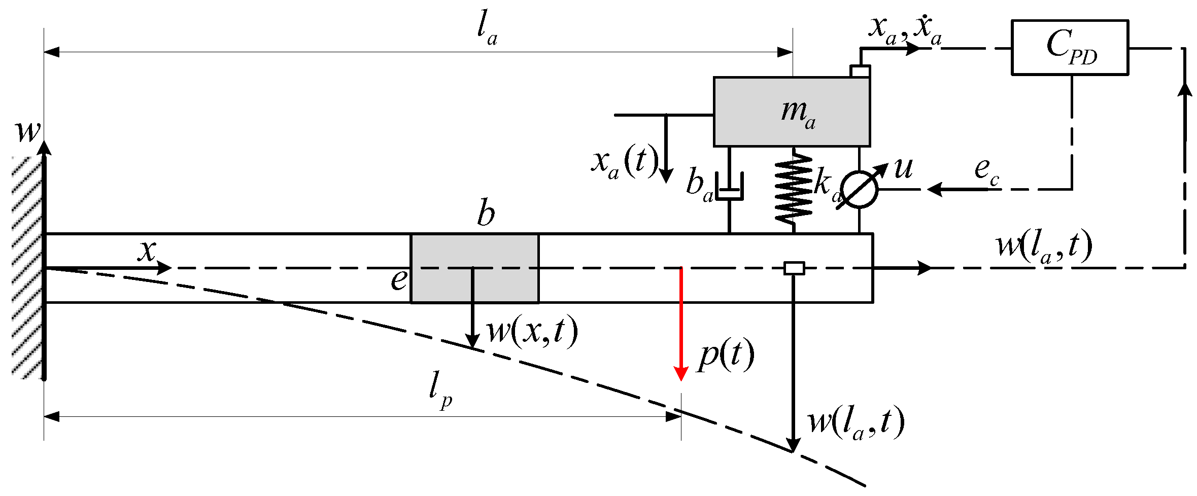
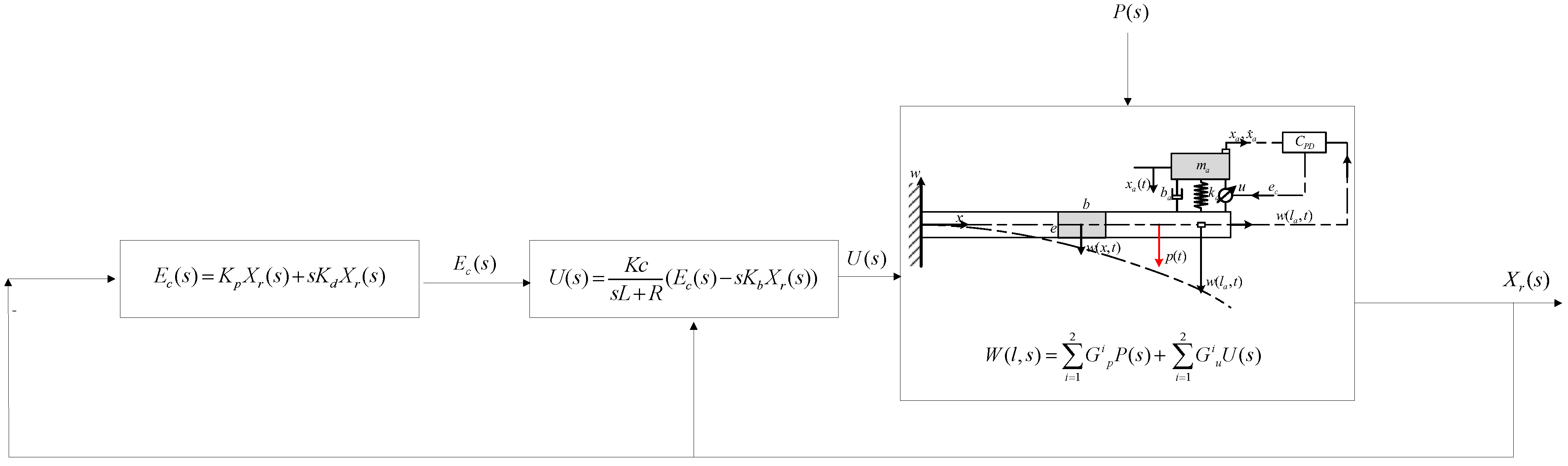
2.2. Active Control for a Cantilever Beam

The active vibration absorber is implemented to a cantilever beam, Figure 3. The force produced by the absorber to the beam is considered as a punctual force. A continuous model of a cantilever beam is used for the analysis. Kinetic and potential energy expressions of the cantilever beam have the following form (9) and (10), where ρ ( x ) is the density, A ( x ) is the section transversal area, w ( x , t ) is the deflection over time, E ( x ) is the Young modulus and I ( x ) is the inertia of the transversal area along the x axis. The perturbance is considered an external force over time p ( t ) placed at a position l p .
T = 1 2 0 l ρ ( x ) A ( x ) w t 2 d x
V = 1 2 0 l E ( x ) I ( x ) 2 w 2 x 2 d x
The deflection of any position along the beam can be represented as the superposition of the modal coordinates [27], which is given by (11), where q i ( t ) is the generalized coordinate related to i-mode of vibration and φ i ( x ) is the normal mode function defined by (12)
w ( x , t ) = i = 1 n q i ( t ) φ i ( x )
φ i ( x ) = C i s e n β i x s e n h β i x α i ( cos β i x cosh β i x ) , i = 1 2 3 n
α i = s e n β i l s e n h β i l cos β i l cosh β i l
According to the procedure developed in [28], using the Lagrange equations for (9) and (10), the dynamics of the cantilever beam are represented by the differential equations system in (14), where m i j is the generalized mass, k i j is the generalized stiffness, h 1 j is the generalized force of disturbance and h 2 j is the generalized force of the force produced by the active vibration absorber at its position along the beam.
i = 1 n m i j q ¨ i ( t ) + i = 1 n k i j q i ( t ) = h 1 j + h 2 j , j = 1 2 . . . n
m i j = 0 l ρ ( x ) A ( x ) φ i ( x ) φ j ( x ) d x = 0 k i j = 0 l E ( x ) I ( x ) d 2 φ i d x 2 d 2 φ j d x 2 d x = 0 S i i j
h 1 j = p ( t ) φ ( l ) j h 2 j = f ( t ) φ ( l ) j j = 1 2
Solving the differential equations system in (14) in the Laplace domain and substituting it in (11), the deflection, in the Laplace domain, along the beam as a function of the disturbance P ( s ) and active force U ( s ) is obtained:
W ( l , s ) = i = 1 2 G i p P ( s ) + i = 1 2 G i u U ( s )
where
G i p ( s ) = G i 1 φ i 2 ( l ) G i u ( s ) = G i 1 m a s 2 m a s 2 + b a s + k a φ 2 i ( l )
G i = m i i s 2 + k i i + m a s 2 ( k a + b a s ) m a s 2 + b a s + k a φ i ( l ) 2
Hence the active control is obtained coupling the equations of the PD control, the electromagnetic actuator and the cantilever beam. Figure 4 shows a scheme of the developed active control of the cantilever beam using the relative position and velocity feedback.

2.3. Simulation

The developed model was simulated using Matlab Simulink® R2022a. Parameters used for the simulation are listed in Table 1. Parameters of the electromagnetic actuator presented in [26] were used. PD control gains must change the dynamic characteristics of the active vibration absorber. Thus, its natural frequency has to be equal to the excitation frequency of the primary system since the inertial force must be equal and opposite to the excitation force. By using Equations (7) and (8), the PD gains were calculated for the second resonant frequency; K p is 606.87 V/m and K d is −3.22 V-s/m.

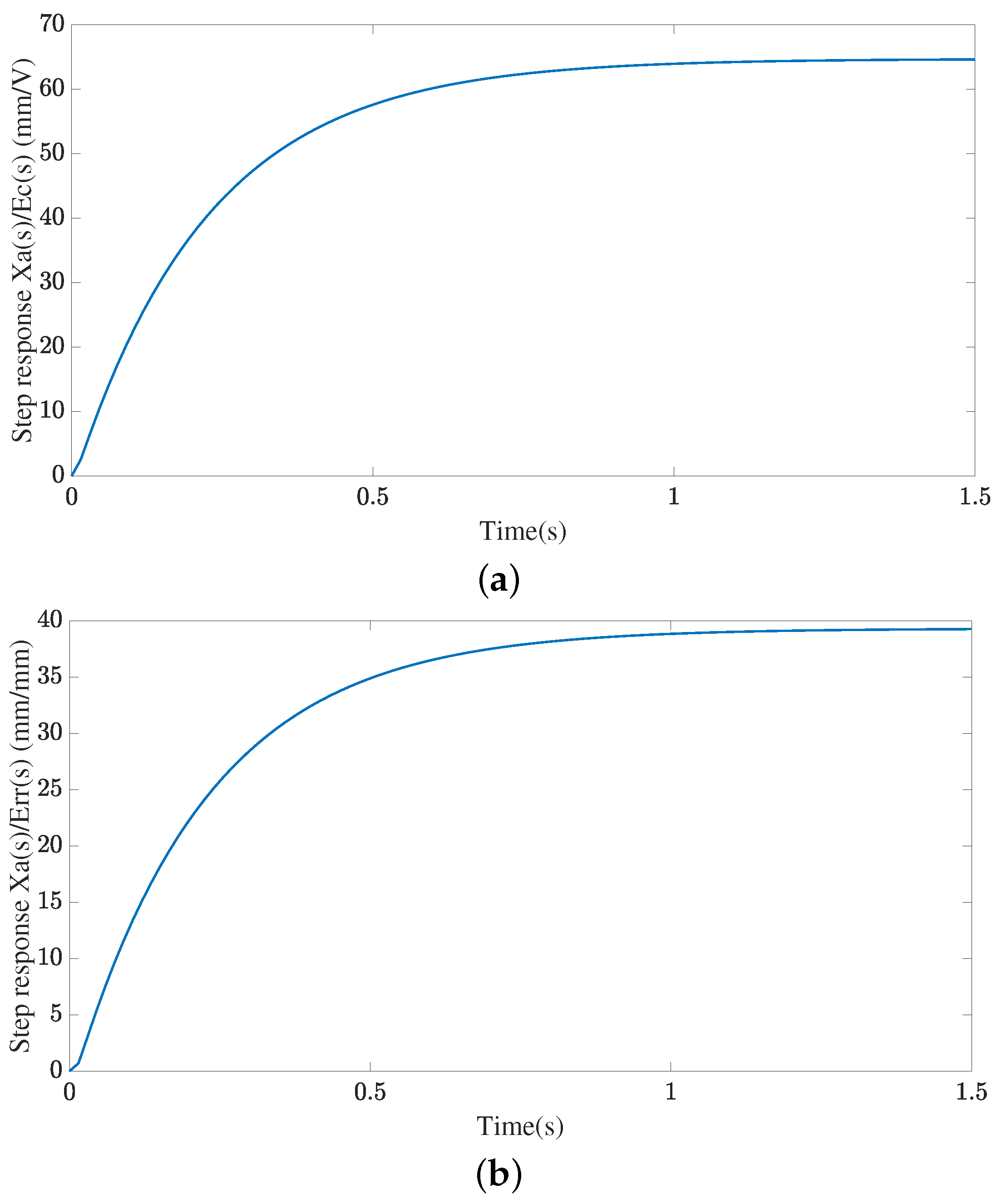
2.3.1. Dynamic Characteristics of the AVA

The dynamic behaviour of only the AVA was evaluated with the parameters established. The step response was calculated with and without control represented as Xa(s)/Ec(s) and Xa(s)/Err(s). The first condition simulates the dynamic behaviour considering just dynamic characteristics of the actuator and the mechanical absorber as an open loop. In this case, the step signal was a voltage unit for the actuator. The second condition simulates the PD control, the actuator and the absorber as an open loop. In this case, the step signal was the error signal calculated as the difference between reference and absorber position.

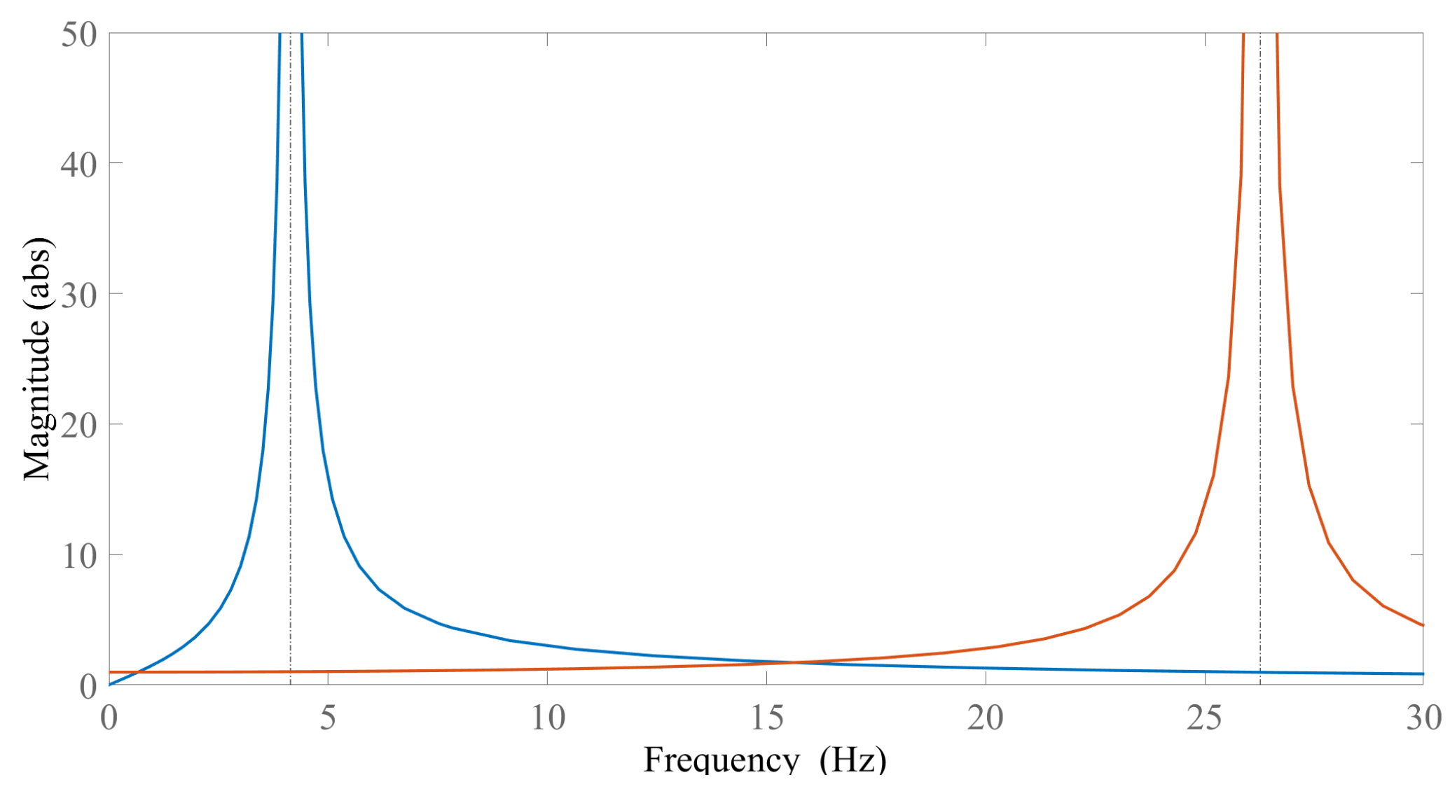
2.3.2. Natural Frequencies of the Cantilever Beam

The addition of a mass and spring after absorber implementation to the cantilever beam changes the original natural frequencies without them. When AVA is off, its dynamical behaviour depends on mass and stiffness mainly while the actuator acts as damping. In this case, natural frequencies of the cantilever beam were calculated numerically with Equation (14) by solving an eigenvalue problem with and without absorber mass and stiffness, simulating a passive absorber case. Three modes of vibration were considered in order to model the dynamical behaviour in Equation (11), since excitation frequency for evaluation was within the first and second modes of vibration.
When AVA is activated, free vibration was simulated by the dynamical response in the time domain after a unitary impulse application in Matlab Simulink.

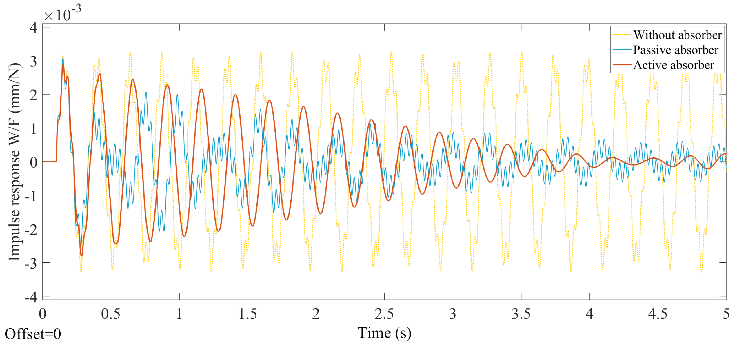
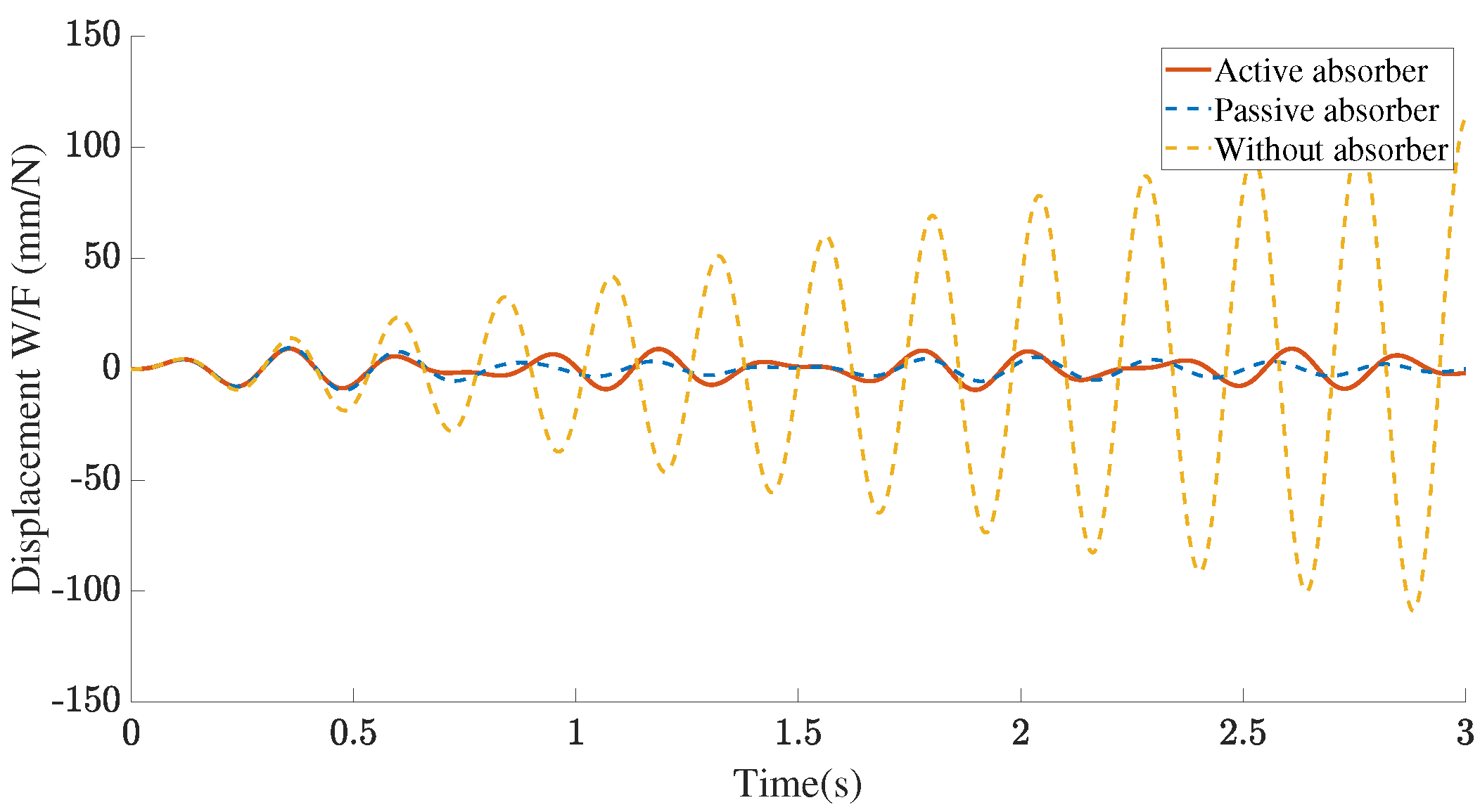
2.3.3. Dynamic Response of the Cantilever Beam

Attenuation of vibration amplitude was evaluated under different conditions with an excitation force located at the free end of the cantilever beam model since it is the most critical location for an external force. The cantilever beam model was excited in its first and second resonant frequency with and without an absorber. Likewise, the dynamic influence of the absorber position at the cantilever beam was evaluated since the maximum vibration attenuation is one of the objectives for designing a solution. The absorber was placed in three different positions at 1/3, 2/3 of its length relative to the fixed end. For each absorber position, the displacement of the free end was obtained over time when the primary system was excited in the second resonant frequency,

3. Results

3.1. AVA Dynamic Characteristics

Natural frequencies of the cantilever beam with and without mass and stiffness of the absorber are shown in Table 2. The response of only the active vibration absorber to a step signal is shown in Figure 5a without a control algorithm. Figure 5b shows the response with PD control in an open loop tuned to the second resonant frequency. In Figure 5a, the input signal was a unit voltage step, there are no overshoots over time and the settling time was 0.87 s. In Figure 5b, the input signal was a unit error step which is the difference between reference and absorber position; the settling time was 0.875 s.
Figure 6 shows the dynamic response in the frequency domain when it is tuned to first and second resonant frequencies. Peaks show the natural frequencies of only the AVA. It can be noticed that they match the desired absorption frequency of the primary system.

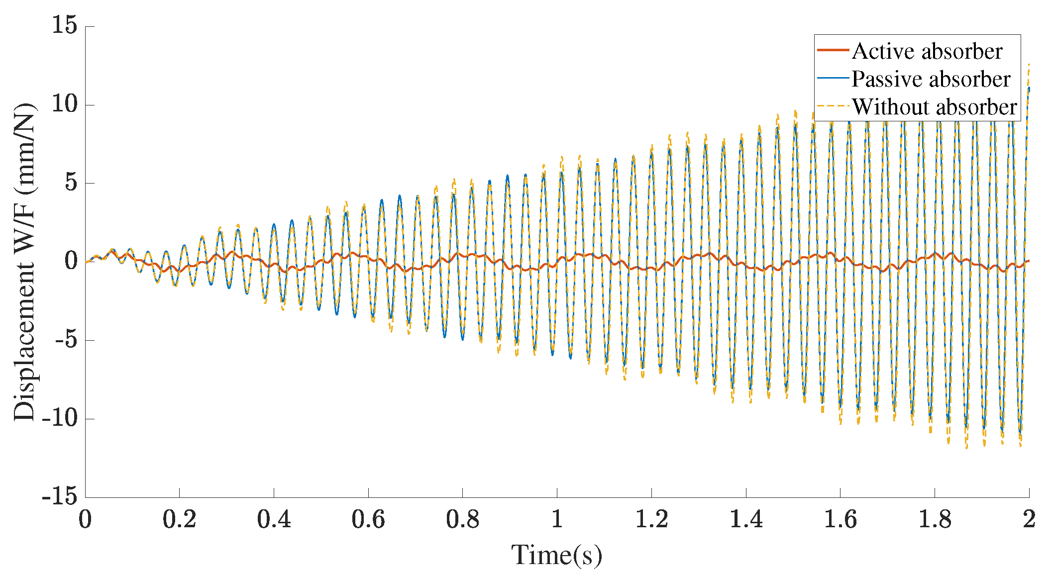
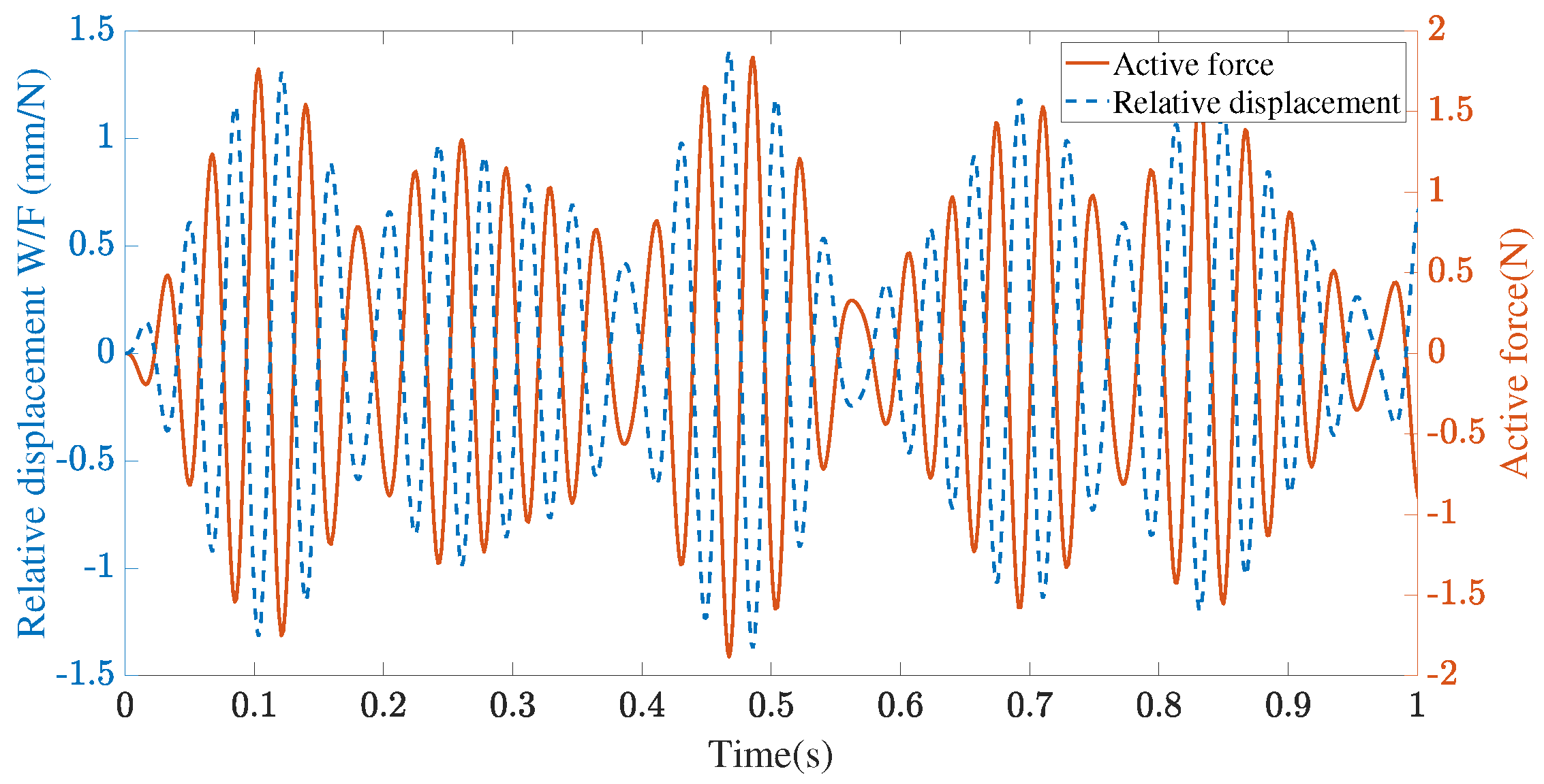
3.2. Dynamic Response

Figure 7 shows the impulse response of the cantilever beam over time with a passive, an active and without an absorber when a unitary impulse was applied at the free end. The AVA was tuned to the second natural frequency of the cantilever beam. It can be seen that response periods of the cantilever beam were different in each case. Likewise, each signal was composed of different frequencies corresponding to the multiples modes of vibration. When a passive absorber was added, the contribution of other modes of vibration increased. The best controlled response was obtained with the AVA. Furthermore, the response period increased with AVA with respect to the cantilever beam without absorber.
Figure 8 shows the dynamic response of the cantilever beam over time with a passive, an active and without an absorber when it is excited in its first resonant frequency. Without an absorber, the vibration amplitude increased over time due to the resonance condition. However, with a passive or an active absorber, the amplitude value was controlled within a range. Figure 9 shows the dynamic response when it is excited in its second resonant frequency. Without an absorber, the vibration amplitude greatly increased over time. A passive absorber was not more effective in this case. The active vibration absorber was effective and controlled a low vibration amplitude over time. Figure 10 shows the active force and relative displacement over time when the cantilever beam was excited in its second resonant frequency. It can be seen that the active force was always opposite and proportional to the relative displacement as an artificial stiffness tuned to that frequency.

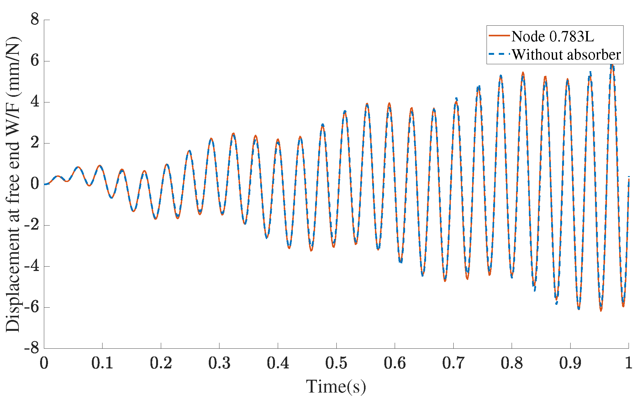
3.3. Position Influence

Figure 11 shows the displacement of the cantilever beam free end when the AVA was placed in three different positions. For all positions, it was effective and reduced the vibration amplitude. Nevertheless, the maximum absorption was obtained when the AVA was placed at the free end, where the external dynamical force acts. Figure 12 shows the dynamic response when the AVA was placed in a node of the primary system and the response was without AVA. The second mode of vibration contains a node at 0.783 of its length where the amplitude is zero. In this case, the AVA was not effective and the vibration amplitude increased over time. It is shown that there was not a significant difference between the case with AVA and without it when it is placed in a node.

4. Discussion

The dynamic behaviour of the cantilever beam is a superposition of modes of vibration with a pounded contribution since a continuous model was used. The addition of an AVA produced a modification of the original dynamic characteristics of the structure. With a passive absorber, mass and stiffness determined how intense the change was in the natural frequencies. With an AVA, the change also depended on control and actuator dynamic characteristics. Impulse responses in time domain have shown that the contribution of different modes of vibration increased with a passive absorber. Nevertheless, with an AVA, the response was more uniform and better controlled with a period higher than the cantilever beam without absorber.
Natural frequencies 3.5 and 4.93 Hz after a passive absorber addition were introduced around the tuning frequency 4.14 Hz. The difference was 15% and 19% when the absorber mass was 2.54 % of the cantilever mass. Since the absorber mass is a few percentage of cantilever mass, the second mode of vibration was not altered and the natural frequency kept its value. Step response of the AVA has shown how intense the PD control gains were in an open loop when this receives the error signal. Since PD gains were calculated in order to tune the AVA to the excitation frequency exactly, the values are unique. However, tuning frequency can be slightly different and continue being effective as passive absorbers within a narrow range around the desired tuning frequency. The frequency range where AVA is effective depends on the components’ capacity. Absorption frequency must be equal to the natural frequency of only the AVA. This relation required an artificial stiffness proportional to the squared absorption frequency. In this sense, a higher absorption frequency increased the active force. Thus actuator capacity must be able to provide a sufficient force with a dynamic behaviour fast enough to keep the AVA tuned.
The vibration amplitude of the cantilever beam increased over time without an absorber in a resonance condition. There were no differences between passive and active absorbers when both were tuned to the same frequency. This is due to the working concept of the AVA. Actuator force is designed to produce a proportional opposite force to the relative displacement between the absorber and the cantilever beam as an artificial stiffness. In this sense, since mass and stiffness of the absorber are tuned to the first resonant frequency, the AVA is already tuned without the active force. The position of the absorber was a significant parameter for the dynamic response. Although the AVA was effective in all positions, the exceptions were nodes of vibration where the amplitudes are zeros. The AVA needed to be placed in positions able to transmit movement in order to produce an inertial force opposite to the excitation external force over time.

5. Conclusions

A model of an active vibration absorber implemented to a continuous cantilever beam was developed, this continuous model represents the most accurate dynamic response of the real structure. Results indicate that the active vibration absorber is able to be tuned to a desired frequency within an excitation frequency range from a primary system and reduce the vibration amplitude, especially in critical conditions corresponding to the resonant frequencies.
The vibration amplitude is absorbed in the whole continuous cantilever beam model, not only at the position of the active vibration absorber. The position of the active absorber at the cantilever beam has a significant influence at the reduction of vibration, especially if it is placed near a vibration node from the primary system, where the active absorber is not effective. It was found that the optimum position for the active vibration absorber corresponds to the position of the maximum vibration amplitude at the primary system. In this sense, a proper formulation of the primary system model and experimental validation are required, especially for complex systems in order to establish the absorption frequency range, optimum position and active absorber physical characteristics.
The analysis of the developed active vibration absorber model is not limited to structures, but is also effective in application to any system.

Author Contributions

Conceptualization, C.R. and J.A.; methodology, C.R. and J.A.; software, C.R.; validation, C.R., J.A. and R.R.; formal analysis, C.R.; investigation, C.R.; data curation, C.R.; writing—original draft preparation, C.R.; writing—review and editing, C.R.; visualization, C.R.; supervision, J.A.; project administration, C.R. All authors have read and agreed to the published version of the manuscript.

Funding

This research received no external funding.

Data Availability Statement

The data presented in this study are available on request from the corresponding author. The data are not publicly available due to the modelling is a part of a research in progress.

Conflicts of Interest

The authors declare no conflict of interest.

References

  1. Orhan, S.; Aktürk, N.; Çelik, V. Vibration monitoring for defect diagnosis of rolling element bearings as a predictive maintenance tool: Comprehensive case studies. NDT E Int. 2006, 39, 293–298. [Google Scholar] [CrossRef]
  2. Sofronas, A. Case Histories in Vibration Analysis and Metal Fatigue for the Practicing Engineer; John Wiley & Sons: Hoboken, NJ, USA, 2012; pp. 245–268. [Google Scholar]
  3. Frahm, H. A Device for Damping Vibrations of Bodies. US Patent 989958A, 18 April 1911. [Google Scholar]
  4. Hartog, J.D. Mechanical Vibrations, 4th ed.; McGraw-Hill: New York, NY, USA, 1956; Volume 1. [Google Scholar]
  5. Soong, T.T. Active structural control in civil engineering. Eng. Struct. 1988, 10, 74–84. [Google Scholar] [CrossRef]
  6. Housner, G.W.; Bergman, L.A.; Caughey, T.K.; Chassiakos, A.G.; Claus, R.O.; Masri, S.F.; Skelton, R.E.; Soong, T.T.; Spencer, B.F.; Yao, J.T. Structural control: Past, present and future. J. Eng. Mech. 1997, 123, 897–971. [Google Scholar] [CrossRef]
  7. Kobori, T.; Koshika, N.; Yamada, K.; Ikeda, Y. Seismic-response-controlled structure with active mass driver system. Part 1: Design. Earthq. Eng. Struct. Dyn. 1991, 20, 133–149. [Google Scholar] [CrossRef]
  8. Kobori, T.; Koshika, N.; Yamada, K.; Ikeda, Y. Seismic-response-controlled structure with active mass driver system. Part 2: Verification. Earthq. Eng. Struct. Dyn. 1991, 20, 151–166. [Google Scholar] [CrossRef]
  9. Chang, C.; Yang, H.T. Control of Buildings Using Active Tuned Mass Dampers. J. Eng. Mech. 1995, 121, 355–366. [Google Scholar] [CrossRef]
  10. Kwak, M.K.; Yang, D.H.; Shin, J.H. Active vibration control of structures using a semi-active dynamic absorber. Noise Control Eng. J. 2015, 63, 287–299. [Google Scholar] [CrossRef]
  11. Yu, W.; Thenozhi, S.; Li, X. Stable active vibration control system for building structures using PD/PID control. IFAC Proc. Vol. 2014, 47, 4760–4765. [Google Scholar] [CrossRef]
  12. Yang, D.H.; Shin, J.H.; Lee, H.W.; Kim, S.K.; Kwak, M.K. Active vibration control of structure by Active Mass Damper and Multi-Modal Negative Acceleration Feedback control algorithm. J. Sound Vib. 2017, 392, 18–30. [Google Scholar] [CrossRef]
  13. Chang, S. Active mass damper for reducing wind and earthquake vibrations of a long-period bridge. Actuators 2020, 9, 66. [Google Scholar] [CrossRef]
  14. Kumar, K.R.; Narayanan, S. Active vibration control of beams with optimal placement of piezoelectric sensor/actuator pairs. Smart Mater. Struct. 2008, 17, 055008. [Google Scholar] [CrossRef]
  15. Cao, H.; Li, Q.S. New control strategies for active tuned mass damper systems. Comput. Struct. 2004, 82, 2341–2350. [Google Scholar] [CrossRef]
  16. Zhou, K.; Li, Q.S.; Li, X. Dynamic Behavior of Supertall Building with Active Control System during Super Typhoon Mangkhut. J. Struct. Eng. 2020, 146, 04020077. [Google Scholar] [CrossRef]
  17. Babaei, M.; Asemi, K.; Safarpour, P. Natural Frequency and Dynamic Analyses of Functionally Graded Saturated Porous Beam Resting on Viscoelastic Foundation Based on Higher Order Beam Theory. J. Solid Mech. 2019, 11, 615–634. [Google Scholar] [CrossRef]
  18. Wang, J.; Liu, Y.; Qin, Z.; Ma, L.; Chu, F. Dynamic performance of a novel integral magnetorheological damper-rotor system. Mech. Syst. Signal Process. 2022, 172, 109004. [Google Scholar] [CrossRef]
  19. Xu, J.; Zhou, W.; Jing, J. An electromagnetic torsion active vibration absorber based on the FxLMS algorithm. J. Sound Vib. 2022, 524, 116734. [Google Scholar] [CrossRef]
  20. Mo, J.; Priefer, R. Medical Devices for Tremor Suppression: Current Status and Future Directions. Biosensors 2021, 11, 99. [Google Scholar] [CrossRef]
  21. Fromme, N.P.; Camenzind, M.; Riener, R.; Rossi, R.M. Design of a lightweight passive orthosis for tremor suppression. J. Neuroeng. Rehabil. 2020, 17, 47. [Google Scholar] [CrossRef]
  22. Tremelo for Essential Tremor | Effective Hand Tremor Device. Available online: https://fivemicrons.com/tremelo/(accessed on 25 February 2023).
  23. Rudraraju, S. Wearable tremor reduction device (trd) for human hands and arms. In Frontiers in Biomedical Devices; American Society of Mechanical Engineers: New York, NY, USA, 2018. [Google Scholar]
  24. Palomera-Arias, R.; Connor, J.J.; Ochsendorf, J.A. Feasibility Study of Passive Electromagnetic Damping Systems. J. Struct. Eng. 2008, 134, 109–158. [Google Scholar] [CrossRef]
  25. Diez-Jimenez, E.; Rizzo, R.; Gómez-García, M.J.; Corral-Abad, E. Review of Passive Electromagnetic Devices for Vibration Damping and Isolation. Shock Vib. 2019, 2019, 1250707. [Google Scholar] [CrossRef]
  26. Elmali, H.; Renzulli, M.; Olgac, N. Experimental comparison of delayed resonator and PD controlled vibration absorbers using electromagnetic actuators. J. Dyn. Syst. Meas. Control. Trans. ASME 2000, 122, 514–520. [Google Scholar] [CrossRef]
  27. Rao, S.S. Mechanical Vibrations, 5th ed.; Pearson: London, UK, 2010; Volume 169, p. 641. [Google Scholar] [CrossRef]
  28. Łatas, W. Application of the continuous dynamic absorbers in local and global vibration reduction problems in beams. Vib. Phys. Syst. 2016, 27, 245–254. [Google Scholar]
Figure 1. Active vibration absorber.
Mathematics 11 02009 g001
Figure 2. Scheme of active vibration absorber control diagram.
Mathematics 11 02009 g002
Figure 3. Cantilever beam implemented with an active vibration absorber at its free end.
Mathematics 11 02009 g003
Figure 4. Active control diagram of a cantilever beam implemented with the active vibration absorber.
Mathematics 11 02009 g004
Figure 5. Step response of the active vibration absorber: (a) without PD control in open loop; (b) with PD control from an error signal in open loop.
Mathematics 11 02009 g005
Figure 6. Frequency response of the active vibration absorber.
Mathematics 11 02009 g006
Figure 7. Impulse response of the cantilever beam at free end.
Mathematics 11 02009 g007
Figure 8. Dynamic response under the first resonant frequency.
Mathematics 11 02009 g008
Figure 9. Dynamic response under the second resonant frequency.
Mathematics 11 02009 g009
Figure 10. Active force and relative displacement under the second resonant frequency.
Mathematics 11 02009 g010
Figure 11. Displacement at free end under the second resonant frequency for the active vibration absorber placed in 1/3, 2/3 of the length and at free end.
Mathematics 11 02009 g011
Figure 12. Displacement at free end under the second resonant frequency for the active vibration absorber placed in a node of the second vibration mode at 0.783 of its length.
Mathematics 11 02009 g012
Table 1. Parameters of the cantilever beam and active absorber.
DescriptionParameterValue
Cantilever beamb50 mm
e5 mm
ρ 7850 kg/m3
A250 mm2
E210 GPa
I5000 mm4
l1 m
Active vibration absorber m a 0.05 kg
k a 141.8 N/m
b a 0.1 N.s/m
R1.6 Ohm
L0.75 mH
K c 3.5 N/A
K b 3.5 V.s/m
Table 2. Natural frequencies of the cantilever beam.
Natural FrequencyWithout AbsorberWith Absorber
First4.14 Hz3.50 Hz
Second26.26 Hz4.93 Hz
Third73.53 Hz26.26 Hz
Disclaimer/Publisher’s Note: The statements, opinions and data contained in all publications are solely those of the individual author(s) and contributor(s) and not of MDPI and/or the editor(s). MDPI and/or the editor(s) disclaim responsibility for any injury to people or property resulting from any ideas, methods, instructions or products referred to in the content.

