Abstract
Analysis of the electromechanical-size-dependent bending of piezoelectric composite structural components with flexoelectricity has been considered by many researchers because of the developments of nanotechnology and the applicability of piezoelectric composite nanobeam structures in Micro/Nano-Electro-Mechanical Systems (MEMS/NEMS). Therefore, the work investigates the size-dependent electromechanical bending of piezoelectrically layered perforated nanobeams resting on elastic foundations including the flexoelectric effect. Within the framework of the modified nonlocal strain gradient elasticity theory, both the microstructure and nonlocality effects are captured. The governing equilibrium equations including piezoelectric and flexoelectric effects are derived using Hamilton’s principle. Closed forms for the non-classical electromechanical bending profiles are derived. The accuracy of the proposed methodology is verified by comparing the obtained results with the available corresponding results in the literature within a 0.3% maximum deviation. Parametric studies are conducted to explore effects of perforation parameters, elastic foundation parameters, geometric dimensions, nonclassical parameters, flexoelectric parameters, as well as the piezoelectric parameters on the bending behavior of piezoelectrically layered perforated nanobeams. The obtained results demonstrate that incorporation of the nondimensional elastic foundation parameters, Kp = 2 and Kw = 20, results in a reduction in the relative percentage reduction in the maximum nondimensional mechanical transverse deflection due to increasing the perforation filling ratio from 0.2 to 1 from 199.86% to 91.83% for a point load and 89.39% for a uniformly distributed load. On the other hand, with Kp = 5 and Kw = 50, the relative percentage difference of the electromechanical bending deflection due to increasing the piezoelectric coefficient, e311, reaches about 8.7% for a point load and 8.5% for a uniformly distributed load at a beam aspect ratio of 50. Thus, the electromechanical as well as mechanical behaviors could be improved by controlling these parameters. The proposed methodology and the obtained results are supportive in many industrial and engineering applications, i.e., MEMS/NEMS.
Keywords:
piezoelectrically layered nanobeam; regular squared perforation; elastic media; electromechanical bending behavior; closed forms; nonlocal strain gradient theory; flexoelectricity MSC:
74F15
1. Introduction
Nowadays, from both the fundamental and application sides, a new mechanical-electrocoupling effect (i.e., direct flexoelectric effect) between the strain gradient and electric polarization, or vice versa, has attracted a fair amount of attention [1,2]. The flexoelectric effect of materials usually intensifies at the microscale even under small deformation owing to the intrinsic scaling of the strain gradient. Due to such a feature, flexoelectricity has attracted much attention in the past decades in a variety of materials such as crystalline ceramics and ferroelectric thin films to develop their electromechanical model [3].
Baroudi et al. [4] developed an analytical model to study static and dynamic responses of piezoelectric flexoelectric strain gradient nanobeams with bidirectional polarization and a self-field effect. Sedighi [5] represented the influence of the nonlinear amplitude of vibration on the dynamic pull-in instability and fundamental frequency of actuated microbeams. Kheibari and Beni [6] studied the free vibration of piezoelectric nanotubes by using Love’s cylindrical thin-shell model. Kaghazian et al. [7] studied the free vibration of a piezoelectric nonlocal Euler–Bernoulli nanobeam. Moory-Shirbani et al. [8] investigated experimentally and numerically a piezoelectrically actuated multilayered imperfect microbeam subjected to an applied electric potential. Chen et al. [9] exploited modified strain gradient theory in analyzing the dynamic responses of a flexoelectricity functionally graded (FG) porous piezoelectric sandwich Euler–Bernoulli nanobeam. Gupta et al. [10] presented the surface and flexoelectric effects on the response of the piezoelectric and dielectric properties of a Boron-Nitride-reinforced nanocomposite. Van Minh and Van Ke [11] developed comprehensive studies on mechanical responses of piezoelectric nanoplate foundations with the flexoelectric effect. Qian and Wang [12] examined the electromechanical coupling bandgap of a locally resonant piezoelectric/elastic phononic crystal double-layer nonlocal nanobeam. Zhao et al. [13] exploited the differential quadrature method to present the effect of porosity and flexoelectricity on the static bending and free vibration of axially FG piezoelectric nanobeams. Malikan and Eremeyev [14] studied the impact of flexoelectricity on a piezoelectric nanobeam involving internal viscoelasticity. Malikan and Eremeyev [15] evaluated the nonlinear bending of a piezo-flexomagnetic strain gradient nanobeam based on an analytical-numerical solution. Monaco et al. [16] developed a trigonometric solution for the bending response of magneto-electro-elastic nanoplates in a hygrothermal environment. Naderi et al. [17] investigated the size-dependent piezoelectric load on the vibration, buckling, and energy harvesting response of local and nonlocal piezoelectric nanobeams. Hao-nan et al. [18] examined the vibration response of rotating FG piezoelectric nonlocal nanobeams by using the differential quadrature method. Ren et al. [19] developed an integral nonlocal gradient piezoelectric model to investigate the bending of an FG piezoelectric nanobeam. Li and Jin [20] explored the electromechanical vibration and induced stresses of a piezoelectric nanobeam with a symmetrical FGM core under low-velocity impact. Ansari et al. [21] developed a numerical study for free vibration analysis of piezoelectric Bernoulli–Euler nonlocal nanobeams considering flexoelectric effects. Alam and Mishra [22] exploited a boundary layer solution to study the post-critical thermo-electromechanical stability of nonlocal strain gradient FG piezoelectric cylindrical shells. Boyina and Piska [23] studied the wave propagation in viscoelastic Timoshenko nanobeams under surface and magnetic field effects.
In the frame of nonlocal strain gradient theory, Lu et al. [24] obtained analytical solutions for natural frequencies of a size-dependent sinusoidal shear deformation nanobeam. She et at. [25] predicted the wave propagation of FG porous nanobeams based on Reddy’s higher-order shear deformation theory. Hashemian et al. [26] studied bending and buckling responses of Timoshenko and higher-order nanobeams. Karami et al. [27] investigated the vibration response of a 2D tapered porous FG Timoshenko beam including temperature and porosity influences on the material properties. Ducottet and El Baroudi [28] derived a mathematical model and frequency equation to study the radial vibration of nanospheres with nonlocal strain gradient theory. Hai et al. [29] studied the vibrational behavior of a sandwich honeycomb piezoelectric actuators microplate resting on the Pasternak elastic foundation. Vahidi-Moghaddam et al. [30] used the Galerkin approach and perturbation technique to examine the nonlinear forced vibrations of nonlocal strain gradient microbeams. Moradi-Dastjerdi and Behdinan [31] evaluated the stress waves in a lightweight substrate plate actuated with piezoelectric layers under sinusoidal pressures. Eghbali et al. [32] investigated vibrations of a cracked nonlocal strain gradient piezoelectric Euler–Bernoulli nanobeam to the effects of Euler–Bernoulli beam theory. Yang et al. [33] investigated the vibration response of unified nanobeams based on two-phase local/nonlocal strain and stress gradient theory, as well as surface elasticity theory. Gui and Wu [34] examined the buckling stability of thermo-magneto-electro-elastic cylindrical nanoshells surrounded by an elastic medium. Zhang et al. [35] exploited Mathieu–Hill equations with the aid of the Navier solution to study the dynamic stability of magneto-electro-thermo-elastic cylindrical nanoshells resting on the Winkler–Pasternak elastic foundations.
Based on the listed review and the authors’ knowledge, investigation of the electromechanical size-dependent bending of piezoelectrically layered perforated nanobeams embedded in a two-parameter elastic foundation with flexoelectricity based on the nonlocal strain gradient theory has not been handled elsewhere. The present work fills this gap. The rest of the paper has been organized as follows: Section 2 presents the mathematical model including equivalent geometrical parameters, displacement relations, basic constitutive equations, electromechanical relations, and modified nonlocal strain gradient theory with flexoelectricity, the energy formulation, and the governing electromechanical equilibrium equations. The analytical solution methodology and verification are proved in Section 3. Verification of the developed procedure and main effects of perforation parameters, elastic foundation parameters, geometric dimensions, nonclassical parameters, flexoelectric parameters, and piezoelectric parameters on the bending behavior of piezoelectrically layered perforated nanobeams is shown and discussed in Section 4. Conclusions and main points are highlighted in Section 5. Future work recommendations are offered in Section 6.
2. Mathematical Model
A piezoelectric layered nanobeam with a perforated core resting on an elastic foundation is presented in Figure 1. The beam is composed of two similar piezoelectric face sheets with the same height hp and material characteristics with elasticity modulus Ep. On the other hand, the perforated core is made of a homogenous linear elastic material with Young’s modulus Ec and height hc. All layers have the same beam length L and width Wb. The overall beam thickness is h, and h = hc + 2hp. The polarization direction of both piezoelectric face sheets is assumed upward. The two face sheets are exposed to two opposite-direction electric fields. The x-axis is directed through the nanobeam length direction, while the z-axis is through the thickness direction.
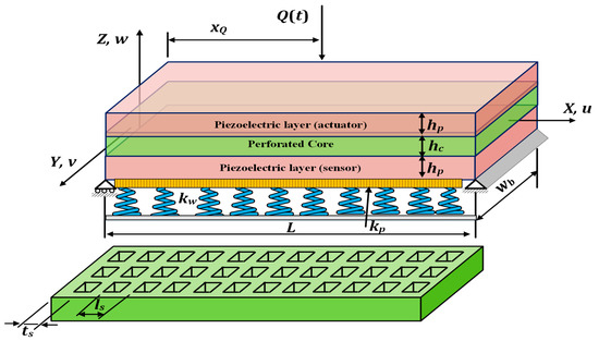
Figure 1.
Geometry of piezoelectrically layered perforated nanobeam embedded in an elastic foundation.
2.1. Equivalent Geometrical Parameters
As shown in Figure 1, the number of holes throughout the beam cross-section is referred to as N. Thus, the filling ratio of the beam can be expressed as [36,37,38,39]
where ts and ls are the length between two holes and the distance between centers of two holes, respectively. The equivalent bending and shear stiffness ratio are given by [40,41,42]
where (EI)eq and (EI)s are, respectively, the equivalent bending stiffness of perforated and solid beams, and (GA)eq and (GA)s are the equivalent shear stiffness of perforated and solid beams, respectively.
2.2. Displacement and Basic Mechanical Relations
Considering the geometry of the composite beam shown in Figure 1, the displacement field according to Euler Bernoulli beam theory (EBBT) is given by [43]
where ux(x, y, z), uy(x, y, z), and uz(x, y, z) are the displacement functions in x, y, and z directions, respectively. refers to the transverse displacement.
The only nonzero strain component based on EBBT is expressed as [44,45]
Considering an isotropic linear elastic material constitutive behavior for the perforated core, the constitutive relation based on the EBBT can be expressed as [46]
with is the equivalent modulus of elasticity, ; E is Young’s modulus; v is Poisson’s ratio; σxx (x, y, z), σyy (x, y, z), and σzz (x, y, z) are the components of the Cauchy normal stress tensor. λ and μ are Lame’s constants in classical elasticity, which are related to the elasticity modulus (E) and Poisson’s ratio (v) as
2.3. Electric Field and the Electromechanical Relations
Incorporating the piezoelectric effect, the electric field is given by [47,48]
where refers to the electric potential field. The electric enthalpy energy density function is expressed as [49,50]
where are, respectively, the second-order permittivity tensor, the fourth-order elasticity tensor, the piezoelectric coefficient tensor, and the electric field strain gradient coupling coefficient, which denotes the higher-order electromechanical coupling induced by strain gradients. In terms of the electric enthalpy energy density, the electric displacement is expressed as [48,51]
Based on the Gaussian theorem, the following condition is verified:
Substituting Equation (7) into Equation (10) yields
The partial derivative of the electric field is expressed as
The electric field can be obtained by integrating Equation (11) with respect to z as
Equation (12) can be rewritten as
in which denotes the initial electric field in the z-direction.
2.4. The Modified Nonlocal Strain Gradient Theory with Flexoelectricity Effect
To incorporate the nonclassical nonlocal as well as the strain gradient effects, the modified nonlocal strain gradient theory is adopted. The “nonlocal strain gradient theory” is a consistent model to describe the small-scale mechanical response of nanostructures. Based on the nonlocal strain gradient theory (NSGT), the stress field accounts for not only the nonlocal elastic stress field but also the strain gradient stress field [52]. Introducing the flexoelectricity effect, the following nonclassical constitutive relations for the components of the stress, the higher gradient strains, and the nonlocal electric potential based on the EBBT are given as:
However, while studying higher-order metaphysic effects such as flexoelectric or flexomagnetic properties, there is a problem. The right-side term in NSGT is the strain gradient, obviously. On the other hand, the term “σ111 εxx,x” is also a strain gradient located in the energy relation. The problem is that these two terms act the same and both are the strain gradient. This occurs for flexoelectric and flexomagnetic effects when using NSGT. This manner is called the “double effect” for the strain gradient [53].
2.5. Energy Formulation and the Governing Equation
Based on the EBBT, the strain energy () is expressed as [52]
with
Then, the strain energy can be evaluated by
Recalling the modified nonlocal strain gradient theory, the following constitutive relation can be written.
where
The work done by the external load and the elastic foundation forces is expressed as
where Ds(.) is the Dirac delta function; x is the abscissa, measured from the left end of the beam; q(x,t) is the applied external shear force; kw and kp are, respectively, Winkler and shear parameters of the elastic foundation.
Applying Hamilton’s principle, the electromechanical equilibrium equation can be expressed as [54]
where refers to the volume of the composite beam, and is the variation in the strain energy, which is evaluated as
The variation in the external work done, , is given by
Substituting Equations (22) and (23) into Equation (21) and evaluating the integrals, the governing electromechanical nonclassical equilibrium equation is derived as
For convenience, the governing electromechanical equilibrium equation is expressed in terms of normalized variables. To do this, the following nondimensional quantities are proposed:
Substituting Equations (16) and (25) into Equation (24), the following electromechanical equilibrium equation is obtained:
3. Analytical Solution Methodology
Within this section, an analytical solutions procedure for the nonclassical electrochemical equilibrium equation is developed. To study and analyze the nonclassical bending behavior of piezoelectrically layered perforated nanobeams embedded in an elastic foundation incorporating the flexoelectric effect based on the nonlocal strain gradient theory, the solution of the equilibrium equation, Equation (26), should be provided. Based on Fourier expansion, closed forms for bending profiles for simply supported piezoelectrically layered perforated nanobeams are derived for different external loading patterns. The boundary conditions associated with simply supported beams are expressed as follows:
The normalized transverse bending deflection and its derivatives with respect to X can be expressed by the Fourier series as
On the other hand, the applied external shear force is expanded using the Fourier series as
where Qn refers to the Fourier expansion coefficients, which depends on the applied loading pattern. For a uniformly distributed shear force [30,40]:
Substituting Equations (27)–(30) into Equation (26) yields
Simplifying Equation (31), the normalized nonclassical electromechanical bending deflection profile,, is derived as
Neglecting the piezoelectric and flexoelectricity effects, the mechanical-size-dependent transverse bending deflection profile, , can be expressed as
Neglecting the nonlocal effect, e0a = 0, as well as the piezoelectric and flexoelectricity effects, the nonclassical mechanical-size-dependent bending based on the microstructure effect can be expressed as
Neglecting the nonclassical effects, the classical electromechanical transverse bending profile can be expressed as
Neglecting the nonclassical as well as the piezoelectric and flexoelectricity effects, the classical mechanical transverse bending profile, , with an elastic foundation can be expressed as
Neglecting the nonclassical as well as the piezoelectric and flexoelectricity and elastic foundation effects, the classical mechanical transverse bending profile, , without an elastic foundation can be expressed as
4. Numerical Results and Discussion
Within this section, the accuracy of the developed procedure is checked and verified. Furthermore, the applicability of the analytical procedure is demonstrated. Numerical experiments are performed to explore the design variables effects on the electromechanical as well as mechanical bending behaviors of piezoelectrically layered perforated nanobeams under different loading profiles.
4.1. Verification of the Developed Methodology
To check the accuracy of the proposed methodology to accurately detect the bending response of nanobeams under different loading conditions, consider a simply supported nanobeam with the following material and geometrical characteristics [55]: the beam is assumed to be made of an elastic material with a modulus of elasticity E = 210 GPa and Poisson’s ratio ν = 0.24. The geometrical variable of the beam is as follows: beam length L = 50 nm; beam cross-sectional area b × H = 5 × 5 nm. To consider a solid beam, the perforation filling ratio is taken as α = 1. The beam is subjected to a central concentrated load of intensity, P = 50 nN, while the distributed load intensity is taken as Q = P/L N/m. The classical and nonclassical bending behaviors of this problem previously discussed by the same problem have been analyzed by Şimşek [55] and Hashemian et al. [26] for solid EBNBT. The developed approach is applied to detect the bending profile for EBNBT with a perforation filling ratio of α = 1. Comparison of the nondimensional deflection, W/H, for EBNB under a central point load and uniformly distributed load are shown in Figure 2 and Figure 3, respectively. An excellent agreement is noticed with the corresponding results reported in Şimşek [55] and Hashemian et al. [26].
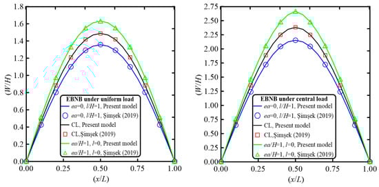
Figure 2.
Comparison of the nondimensional bending profiles with the normalized axial coordinate for EBNB under uniformly distributed and central loading conditions for both classical and nonclassical analyses (α = 1, P0 = 50 nN, Q = 1 N/m, kw = kp = 0).
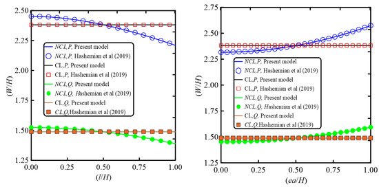
Figure 3.
Comparison of the nondimensional maximum bending with the normalized nonlocal and strain gradient parameters for EBNB under uniformly distributed and central loading conditions for both classical and nonclassical analyses (α = 1, P0 = 50 nN, Q = 1 N/m, kw = kp = 0, ea/H = 0.5 for variable lc and lc/H = 0.5 for variable ea/H, H beam thickness).
We seek a deeper verification of the proposed analytical procedure to check the accuracy of the analytical procedure to efficiently investigate the static behavior of the beam structure embedded in an elastic foundation. For this comparison, the following nondimensional maximum central deflection parameter is defined: , where Eeq is the equivalent elasticity modulus, which can be expressed as , where λ is Lame’s constant, , and G is the rigidity modulus, . q is the intensity of the distributed load and L is the beam length. The nondimensional elastic foundation parameters are defined as Comparisons of the nondimensional maximum central deflection parameter, , for a simply supported beam (SS) under a uniformly distributed load for different values of the nondimensional elastic foundation parameters, Kw and Kp, for beam aspect ratio, L/H = 120, are depicted in Table 1. Excellent agreement with the results reported by [56,57] is observed.

Table 1.
Comparison of the estimated maximum classical nondimensional central transverse deflection for simply supported (SS) beam embedded in two-parameter elastic foundation under uniformly distributed load of intensity q at beam aspect ratio L/H = 120 at different values of the elastic foundation parameters and Poisson’s ratio ν = 0.3.
4.2. Numerical Experiments and Discussion
To demonstrate the effectiveness of the developed procedure to efficiently explore the classical and nonclassical electromechanical as well as the mechanical bending behavior of a piezoelectrically layered perforated nanobeam embedded in an elastic medium under uniformly or concentrated loads, consider a simply supported beam with geometrical and material characteristics shown in Table 2. Both the uniformly distributed load q with intensity 1 N/m and central point load P = q × L are considered and discussed. Numerical experiments are performed by applying the developed procedure to explore the influences of the perforation configuration parameters, the elastic foundation parameters, the strain gradient parameter, the nonlocal parameter, the piezoelectric coefficient, and the electric-field–strain-gradient coupling coefficient on the classical and size-dependent electromechanical as well as the mechanical bending behaviors.
Table 2.
Geometrical and material characteristics of the piezoelectric composite nanobeam.
To investigate the electromechanical as well as the mechanical bending behaviors, the following nondimensional variables are defined: for the electromechanical behavior, , and for the mechanical bending behavior, hp = 0,
The dependency of the nonclassical and classical electromechanical and mechanical bending deflection, Δmax, on the nondimensional elastic foundation parameter Kw at different values of perforation filling ratio is illustrated in Figure 4. It is observed that the maximum nondimensional transverse deflection nonlinearly decreases with the increase in the nondimensional foundation parameter Kw due to decreasing the overall system flexibility for classical and nonclassical electromechanical and mechanical behaviors. Incorporating the piezoelectric effect results in a greater stiffening effect, leading to a greater decrease in the maximum nondimensional transverse deflection compared with the corresponding mechanical behavior. Considering the applied loading pattern, larger values of the maximum nondimensional bending deflection are detected under the action of the applied point load compared with the corresponding uniformly distributed load. On the other hand, regarding the effect of filling ratio, it may be seen that the mechanical behavior is significantly influenced by the filling ratio while it has no significant effect on the electromechanical bending behavior. Increasing the perforation filling ratio results in smaller values of the maximum nondimensional transverse deflection. Additionally, it may be noticed that incorporating the nonlocality effect leads to a softening effect and, thus, larger values of the nondimensional bending deflection compared with the corresponding classical behavior. On the other hand, introduction of the nonclassical strain gradient effect results in a stiffening effect, so smaller values of the nonclassical bending deflection are detected compared with the corresponding classical behavior.
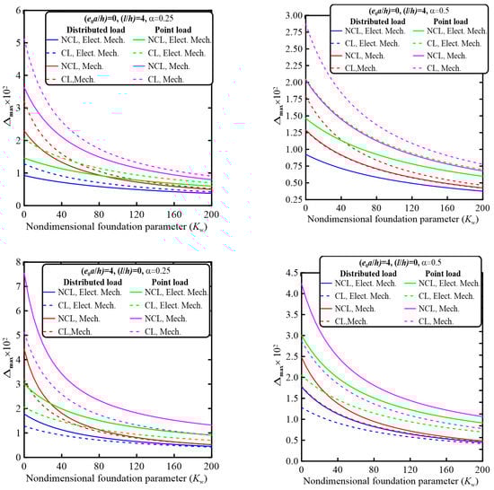
Figure 4.
Variation in the maximum transverse deflection Δmax with the nondimensional elastic foundation parameter Kw for nonclassical and classical electromechanical and mechanical behaviors under uniformly distributed and point loads at different values of perforation filling ratio, α = 0.25 and 0.5, at N = 4 and beam aspect ratio L/h = 20, e311 = −4.1 C/m2, μ3111 = 5 × 10⁻⁸ C/m, a33 = 7.124 × 10⁻⁹ C/m2 K, and Kp = 0.
Variations in the maximum nondimensional transverse deflection Δmax with the nondimensional elastic foundation parameter Kp for nonclassical and classical electromechanical and mechanical behavior under uniformly distributed and point loads at different values of perforation filling ratio are depicted in Figure 5. It may be observed that almost the same qualitative response is observed; the maximum nondimensional transverse deflection nonlinearly decreases with the increase in the nondimensional elastic foundation parameter, Kp.
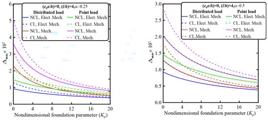
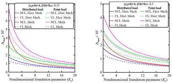
Figure 5.
Variation in the maximum transverse deflection Δmax with the nondimensional elastic foundation parameter Kp for nonclassical and classical electromechanical and mechanical behavior under uniformly distributed and point loads at different values of perforation filling ratio α at N = 4 and beam aspect ratio L/h = 20, α = 0.25 and 0.5, e0a/h = 0, l/h = 2, e311 = −4.1 C/m2, μ3111 = 5 × 10⁻⁸ C/m, a33 = 7.124 × 10⁻⁹ C/m2 K, and Kw = 0.
For deep investigation of the influence of the elastic foundation parameter Kw on the maximum nondimensional transverse deflection, the relative percentage difference of the maximum transverse deflection due to increasing the nondimensional elastic foundation parameter Kw is given by The relative percentage difference for the electromechanical and mechanical nonclassical and classical behaviors at different values of α and nonclassical parameters for point and uniformly distributed loading is depicted in Table 3. It is observed that increasing the filling ratio significantly affects this relative percentage difference for the mechanical behavior, while it has an insignificant effect on the electromechanical behavior. Additionally, the uniformly distributed loading produces larger values of the relative percentage difference compared with the corresponding cases of the concentrated point loads for both electromechanical and mechanical behaviors.
Table 3.
The relative percentage difference in the transverse deflection, , due to increasing the nondimensional elastic foundation parameter, Kw, for electromechanical and mechanical nonclassical and classical behaviors for different values of filling ratio and nonclassical parameters under point and uniformly distributed loads at perforation filling ratio, α = 0.25 and 0.5, at N = 4 and beam aspect ratio L/h = 20, e311 = −4.1 C/m2, μ3111 = 5 × 10⁻⁸ C/m, a33 = 7.124 × 10⁻⁹ C/m2 K, Kw = 0 to 200 and Kp = 0.
The relative percentage difference of the maximum nondimensional transverse deflection due to increasing the nondimensional elastic foundation parameter Kp is given by Table 4 illustrates the relative percentage difference for the electromechanical and mechanical nonclassical and classical behaviors at different values of α and nonclassical parameters for point and uniformly distributed loading conditions. It may be noticed that the relative percentage difference is more sensitive to the nondimensional foundation parameter Kp compared to Kw. Larger values of this relative percentage difference are obtained compared to those obtained due to Kw.
Table 4.
The relative percentage difference in the transverse deflection, x, due to increasing the nondimensional elastic foundation parameter Kp for electromechanical and mechanical nonclassical and classical behaviors for different values of filling ratio and nonclassical parameters under point and uniformly distributed loads at perforation filling ratio, α = 0.25 and 0.5, at N = 4 and beam aspect ratio L/h = 20, e311 = −4.1 C/m2, μ3111 = 5 × 10⁻⁸ C/m, a33 = 7.124 × 10⁻⁹ C/m2 K, Kp = 0 to 20 and Kw = 0.
The dependency of the nondimensional bending deflection on the perforation filling ratio for electromechanical and mechanical nonclassical and classical behaviors under uniformly distributed and point loads is shown in Figure 6. It may be noticed that, due to decreasing the overall beam flexibility, the maximum nondimensional mechanical bending deflection decreases with the increase in the perforation filling ratio, while there is no significant effect of the filling ratio on the electromechanical bending behavior.
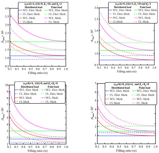
Figure 6.
Variation in the maximum transverse deflection Δmax with the perforation filling ratio α for nonclassical and classical electromechanical and mechanical behavior under uniformly distributed and point loads at different values of the nonclassical and elastic foundation parameters at N = 4 and beam aspect ratio L/h = 20, α = 0.2 to 1, e311 = −4.1 C/m2, μ3111 = 5 × 10⁻⁸ C/m, a33 = 7.124 × 10⁻⁹ C/m2 K, and Kp = 0, 2 and Kw = 0, 20.
For quantitative investigation of the significant effect of the perforation filling ratio α on the maximum nondimensional transverse deflection, the relative percentage difference of the maximum nondimensional transverse deflection due to increasing α at a constant value of the number of hole rows N is given by Table 5 shows the relative percentage difference for the electromechanical and mechanical nonclassical and classical behaviors at different values of the elastic foundation and nonclassical parameters for point and uniformly distributed loading conditions. It is seen that the filling ratio significantly affects the mechanical transverse deflection, while it has an insignificant influence on the electromechanical behavior. This influence decreases with the incorporation of the elastic foundation parameters.
Table 5.
The relative percentage difference in the transverse deflection due to increasing the perforation filling ratio α for electromechanical and mechanical nonclassical and classical behaviors for different values of the nondimensional elastic foundation and nonclassical parameters under point and uniformly distributed loads at perforation filling ratio, α = 0.2 and 0.5, at N = 4 and beam aspect ratio L/h = 20, e311 = −4.1 C/m2, μ3111 = 5 × 10⁻⁸ C/m, a33 = 7.124 × 10⁻⁹ C/m2 K, and α = 0.2 to 1.
The variation in the maximum nondimensional transverse bending deflection with the number of holes throughout the beam cross-section N for electromechanical and mechanical bending behaviors is depicted in Figure 7.
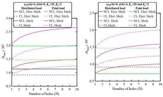
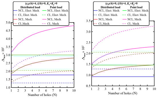
Figure 7.
Variation in the maximum normalized transverse deflection Δmax with the number of holes throughout the cross-section N for nonclassical and classical electromechanical and mechanical behavior under uniformly distributed and point loads at different values of the nonclassical and elastic foundation parameters at α = 0.5 and beam aspect ratio L/h = 20, N = 1 to 10, e311 = −4.1 C/m2, μ3111 = 5 × 10⁻⁸ C/m, a33 = 7.124 × 10⁻⁹ C/m2 K, and Kp = 0, 2 and Kw = 0, 20.
Keeping the value of perforation filling ratio constant, investigating the quantitative effect of the number of hole rows N on the maximum nondimensional transverse deflection, the relative percentage difference of the maximum nondimensional transverse deflection due to increasing N is defined as The relative percentage difference for electromechanical and mechanical nonclassical and classical behaviors at different values of the nondimensional elastic foundation and nonclassical parameters for point and uniformly distributed loading conditions is presented in Table 6. It may be noted that significant values of the relative percentage difference are investigated for the mechanical behaviors for both types of loading conditions while insignificant values are detected for the electromechanical bending behavior.
Table 6.
The relative percentage difference in the transverse deflection due to increasing the number of hole rows N for electromechanical and mechanical nonclassical and classical behaviors for different values of the nondimensional elastic foundation and nonclassical parameters under point and uniformly distributed loads at perforation filling ratio, α = 0.5, and beam aspect ratio L/h = 20, e311 = −4.1 C/m2, μ3111 = 5 × 10⁻⁸ C/m, a33 = 7.124 × 10⁻⁹ C/m2 K, and N = 1 to 10.
It may be seen that the electromechanical bending behavior is independent of the number of holes while the mechanical bending behavior is significantly affected; larger values of the maximum nondimensional bending deflection are obtained with the increase in the number of holes due to increasing the system flexibility.
The dependency of the nonclassical electromechanical and mechanical bending behavior on the nondimensional strain gradient parameter is illustrated in Figure 8. It is seen that the maximum nondimensional transverse deflection is nonlinearly dependent on the nondimensional strain gradient parameter. Increasing the nondimensional strain gradient parameter results in decreasing the maximum nondimensional bending deflection due to increasing the overall system stiffness. Additionally, decreasing the beam thickness leads to a greater decrease in the strain gradient effect; a greater decrease in the nonclassical electromechanical and mechanical bending behavior is observed at small values of beam thickness. It is also observed that the classical bending behavior is detected at (e0a/h) = (l/h).
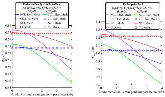
Figure 8.
Variation in the maximum normalized transverse deflection Δmax with the nondimensional strain gradient parameter (l/h) for nonclassical and classical electromechanical and mechanical behaviors under uniformly distributed and point loads at different values of the nonclassical and elastic foundation parameters at α = 0.5 and beam aspect ratio L/h = 10, 20, L = 100 nm, N = 4, e311 = −4.1 C/m2, μ3111 = 5 × 10⁻⁸ C/m, a33 = 7.124 × 10⁻⁹ C/m2 K, and Kp = 5 and Kw = 50.
Variations in the maximum nondimensional bending deflection with the nondimensional nonlocal parameter for electromechanical and mechanical behavior are shown in Figure 9. It may be noticed that the nonclassical electromechanical and mechanical bending behavior is also nonlinearly dependent on the nondimensional nonlocal parameter. Increasing the nondimensional nonlocal parameter produces larger values of the maximum nondimensional bending deflection due to the associated softening effect. In addition, a more significant effect is noticed at smaller beam thickness.
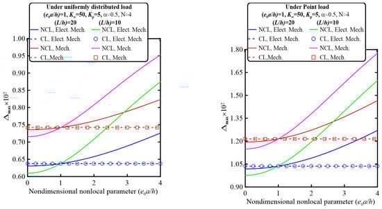
Figure 9.
Variation in the maximum normalized transverse deflection Δmax with the nondimensional nonlocal parameter (e0a/h) for nonclassical and classical electromechanical and mechanical behaviors under uniformly distributed and point loads at different values of the nonclassical and elastic foundation parameters at α = 0.5 and beam aspect ratio L/h = 10, 20, L = 100 nm, N = 4, e311 = −4.1 C/m2, μ3111 = 5 × 10⁻⁸ C/m, a33 = 7.124 × 10⁻⁹ C/m2 K, and Kp = 5 and Kw = 50.
To investigate the influence of the strain gradient and the nonlocal parameters on the nonclassical electromechanical as well as the mechanical bending behaviors, the relative percentage difference of the maximum nondimensional transverse deflection due to increasing the nondimensional strain gradient parameter (l/h) is defined as , while it is defined due to increasing the nondimensional nonlocal parameter (ea/h) as . The relative percentage difference, and , for nonclassical electromechanical and mechanical behaviors at different values of the beam aspect ratio for point and uniformly distributed loading conditions is presented in Table 7. It may be noted that larger values of the nonclassical electromechanical and mechanical behaviors are detected at smaller values of the beam aspect ratio.
Table 7.
The relative percentage difference in the transverse deflection due to increasing the nondimensional strain gradient parameter (l/h), , and the nondimensional nonlocal parameter (ea/h), , for electromechanical and mechanical nonclassical behaviors under point and uniformly distributed loads at beam aspect ratio L/h = 10, 20, e311 = −4.1 C/m2, μ3111 = 5 × 10⁻⁸ C/m, a33 = 7.124 × 10⁻⁹ C/m2 K, Kw = 50, Kp = 5, α = 0.5, and N = 4.
Variations in the maximum normalized transverse deflection Δmax with the piezoelectric coefficient e311 for nonclassical and classical electromechanical and mechanical behaviors under uniformly distributed and point loads at different values of the nonclassical and elastic foundation parameters are depicted in Figure 10. It may be noticed that increasing the absolute value of the piezoelectric coefficient results in the stiffening effect. This leads to decreasing the maximum nondimensional electromechanical bending deflection. In addition, it is noticed that larger values of the nondimensional bending deflection are detected at smaller beam aspect ratios. Additionally, a more significant difference between the nonclassical and classical bending behavior is observed due to the point load compared with the corresponding cases of the uniformly distributed load.
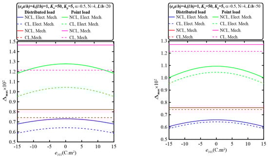
Figure 10.
Variation in the maximum normalized transverse deflection Δmax with the piezoelectric coefficient e311 for nonclassical and classical electromechanical and mechanical behaviors under uniformly distributed and point loads at different values of the nonclassical and elastic foundation parameters at α = 0.5 and beam aspect ratio L/h = 20, 50, hp = 1 nm, hc = 3 nm, h = 15 nm, N = 4, μ3111 = 5 × 10⁻⁸ C/m, a33 = 7.124 × 10⁻⁹ C/m2 K, and Kp = 5 and Kw = 50.
The dependency of the maximum normalized transverse deflection Δmax on the electric-field–strain-gradient coupling coefficient μ3111 for nonclassical and classical electromechanical and mechanical behaviors under uniformly distributed and point loads at different values of the nonclassical and elastic foundation parameters is illustrated in Figure 11. It may be noticed that the electromechanical bending deflection is insignificantly affected by the electric-field–strain-gradient coupling coefficient; almost constant electromechanical bending behavior is detected.
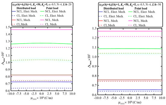
Figure 11.
Variation in the maximum normalized transverse deflection Δmax with the electric-field–strain-gradient coupling coefficient μ3111 for nonclassical and classical electromechanical and mechanical behaviors under uniformly distributed and point loads at different values of the nonclassical and elastic foundation parameters at α = 0.5 and beam aspect ratio L/h = 20, 50, hp = 1 nm, hc = 3 nm, h = 15 nm, N = 4, e311 = −4.1 C/m2, a33 = 7.124 × 10⁻⁹ C/m2 K, and Kp = 5 and Kw = 50.
The quantitative influences of the piezoelectric coefficient e311 as well as the electric-field–strain-gradient coupling coefficient μ3111 on the electromechanical bending behavior could be investigated by defining the relative percentage difference of the maximum nondimensional transverse deflection due to increasing the piezoelectric coefficient e311 as , while it is defined due to increasing the electric-field–strain-gradient coupling coefficient μ3111 as . The relative percentage difference, and , for nonclassical and classical electromechanical bending behaviors at different values of the beam aspect ratio for point and uniformly distributed loading conditions is shown in Table 8. It is seen that larger values of the relative percentage differences are detected due to increasing the piezoelectric coefficient, e311, especially at larger values of beam aspect ratio, while insignificant values are observed due to increasing the electric-field–strain-gradient coupling coefficient, μ3111.
Table 8.
The relative percentage difference in the transverse deflection due to increasing the piezoelectric coefficient e311 and the electric-field–strain-gradient coupling coefficient (μ3111) for electromechanical and mechanical nonclassical and classical behaviors for different values of filling ratio under point and uniformly distributed loads at beam aspect ratio L/h = 20, 50, abs(e311) = −(0 to 15) C/m2, abs (μ3111) = (0 to 10) × 10−8 C/m, a33 = 7.124 × 10⁻⁹ C/m2 K, Kw = 50, Kp = 5, α = 0.5, N = 4, .
5. Conclusions
A nonclassical size-dependent model is developed to explore the electromechanical bending response of a perforated nanobeam layered with two piezoelectric face sheets embedded in an elastic foundation including the flexoelectric effect. A squared perforation pattern with regular order is considered for the perforated core. The equivalent geometrical variables of the perforated core are expressed in explicit forms. In the context of 3D continuum mechanics, all kinematics and kinetics relations are expressed based on the Euler Bernoulli beam theory (EBBT). The Hamilton Principle is adopted to derive the electromechanical equilibrium equation, which is analytically solved for the bending behavior of a simply supported beam structure under uniform and concentrated loads. Numerical experiments are performed to investigate influences of the perforation parameters, elastic foundation parameters, nonclassical parameters, and the piezoelectric and flexoelectric parameters on the bending performance of piezoelectrically layered perforated nanobeams. The following remarks are derived:
- ✓
- The electromechanical bending is affected by the piezoelectric coefficient, e311. It decreases with the increase in the absolute value of the piezoelectric coefficient. Due to increasing the absolute value of the piezoelectric coefficient from 0 to 15, the relative percentage difference of the nondimensional maximum transverse deflection reaches about 8.7% for a point load and about 8.5% for a uniformly distributed load at a beam slenderness ratio of 50.
- ✓
- On the contrary, the electromechanical bending behavior is slightly affected by the electric-field–strain-gradient coupling coefficient, μ3111; almost constant electromechanical bending behavior is obtained with increasing μ3111. With the increase in the absolute value of the electric-field–strain-gradient coupling coefficient, μ3111, from 0 to 10, the relative percentage difference of the nondimensional maximum transverse deflection reaches about 0.9274% for a point load and about 0.3654% for a uniformly distributed load.
- ✓
- The elastic foundation parameters have a significant effect on the electromechanical and mechanical bending behavior. The bending deflection is nonlinearly dependent on the elastic foundation parameters, Kw and Kp. The elastic foundation introduces a stiffening effect and, thus, smaller values of the bending deflection are produced with increasing these parameters. Increasing the nondimensional foundation parameter, Kw, from 0 to 200 produces a relative percentage difference in the maximum transverse deflection of 74.54% for the electromechanical behavior and 88.29% for the mechanical behavior at a perforation filling ratio of 0.25. Furthermore, increasing the nondimensional foundation parameter Kp from 0 to 20 results in a relative percentage difference of the maximum transverse deflection of 73.8254% for the electromechanical behavior and 87.584% for the mechanical behavior.
- ✓
- The perforation configuration parameters greatly affect the mechanical bending behavior. Increasing the perforation filling ratio at a constant number of holes results in a decrease in the mechanical bending deflection. The relative percentage difference in the maximum mechanical transverse deflection reaches about 199.86% due to increasing the filling ratio from 0.2 to 1 without the elastic foundation, while this percentage difference is decreased to 106.94% for the nonclassical mechanical behavior and 91.83% for the classical mechanical behavior under the point load with elastic foundation parameters Kw = 20 and Kp = 2. Furthermore, increasing the number of holes increases the mechanical bending deflection. The relative percentage difference of the maximum transverse deflection reaches 34.1643% without the elastic foundation, while this difference is decreased to 24.28% with elastic foundation constants Kw = 20 and Kp = 2.
- ✓
- Utilizing the modified nonlocal strain gradient provides system flexibility to control stiffening and softening effects. Incorporating the nonlocal effect produces a softening effect, thus increasing the system flexibility. On the other hand, introduction of the strain gradient effect results in a stiffening effect, which leads to smaller values of the bending deflection. Due to increasing the nondimensional strain gradient parameter (l/h) from 1 to 4, the relative percentage difference of the maximum transverse deflection reaches 41.132% for the electromechanical behavior and 37.6% for the mechanical behavior at a beam aspect ratio of 10. Further increasing the nondimensional nonlocality parameter (ea/h) from 1 to 4 produces a relative percentage difference of 53.97% for the electromechanical behavior and 46.17% for the mechanical behavior.
- ✓
- The applied loading pattern significantly affects the bending performance; larger values of the transverse bending deflection are detected with the point load compared with that obtained by the corresponding uniformly distributed loading patterns.
6. Future Work Recommendations
- ✓
- The proposed methodology could be extended to include more nonclassical phenomena such as surface stress effects.
- ✓
- To increase the flexibility of the developed procedure and improve the mechanical performance, a viscoelastic effect could be included in the bulk material as well as the elastic foundation.
Author Contributions
Conceptualization, G.S.A. and M.A.E.; Methodology, A.A.A. and H.A.S.; Formal analysis, A.A.A., H.A.S. and M.A.E.; Investigation, G.S.A.; Resources, A.A.A. and M.A.E.; Data curation, H.A.S.; Writing—original draft, A.A.A.; Writing—review & editing, M.A.E.; Project administration, G.S.A.; Funding acquisition, H.A.S. All authors have read and agreed to the published version of the manuscript.
Funding
Institutional Fund Projects under grant no. IFPIP (449-135-1443).
Informed Consent Statement
Not applicable.
Data Availability Statement
Not applicable.
Acknowledgments
This research was funded by the Institutional Fund Projects under grant no. IFPIP (449-135-1443). The authors gratefully acknowledge technical and financial support provided by the Ministry of Education and King Abdulaziz University, DSR in Jeddah, Saudi Arabia.
Conflicts of Interest
The authors declare no conflict of interest.
References
- Wang, W.; Li, M.; Jin, F.; He, T.; Ma, Y. Nonlinear magnetic-mechanical-thermo-electric coupling characteristic analysis on the coupled extensional and flexural vibration of flexoelectric energy nanoharvester with surface effect. Compos. Struct. 2023, 308, 116687. [Google Scholar] [CrossRef]
- Shi, Y.; Li, N.; Wang, Y.; Ye, J. An analytical model for nonlinear magnetoelectric effect in laminated composites. Compos. Struct. 2021, 263, 113652. [Google Scholar] [CrossRef]
- Deng, F.; Yu, W.; Liang, X.; Shen, S. A Mixed Finite Element Method for Large Deformation of Flexoelectric Materials. Appl. Math. Model. 2023, 118, 303–321. [Google Scholar] [CrossRef]
- Baroudi, S.; Najar, F.; Jemai, A. Static and dynamic analytical coupled field analysis of piezoelectric flexoelectric nanobeams: A strain gradient theory approach. Int. J. Solids Struct. 2018, 135, 110–124. [Google Scholar] [CrossRef]
- Sedighi, H.M. Size-dependent dynamic pull-in instability of vibrating electrically actuated microbeams based on the strain gradient elasticity theory. Acta Astronaut. 2014, 95, 111–123. [Google Scholar] [CrossRef]
- Kheibari, F.; Beni, Y.T. Size dependent electro-mechanical vibration of single-walled piezoelectric nanotubes using thin shell model. Mater. Des. 2017, 114, 572–583. [Google Scholar] [CrossRef]
- Kaghazian, A.; Hajnayeb, A.; Foruzande, H. Free vibration analysis of a piezoelectric nanobeam using nonlocal elasticity theory. Struct. Eng. Mech. 2017, 61, 617–624. [Google Scholar] [CrossRef]
- Moory-Shirbani, M.; Sedighi, H.M.; Ouakad, H.M.; Najar, F. Experimental and mathematical analysis of a piezoelectrically actuated multilayered imperfect microbeam subjected to applied electric potential. Compos. Struct. 2018, 184, 950–960. [Google Scholar] [CrossRef]
- Chen, Q.; Zheng, S.; Li, Z.; Zeng, C. Size-dependent free vibration analysis of functionally graded porous piezoelectric sandwich nanobeam reinforced with graphene platelets with consideration of flexoelectric effect. Smart Mater. Struct. 2021, 30, 035008. [Google Scholar] [CrossRef]
- Gupta, M.; Meguid, S.A.; Kundalwal, S.I. Synergistic effect of surface-flexoelectricity on electromechanical response of BN-based nanobeam. Int. J. Mech. Mater. Des. 2022, 18, 3–19. [Google Scholar] [CrossRef]
- Van Minh, P.; Van Ke, T. A Comprehensive Study on Mechanical Responses of Non-uniform Thickness Piezoelectric Nanoplates Taking into Account the Flexoelectric Effect. Arab. J. Sci. Eng. 2022, 1–26. [Google Scholar] [CrossRef]
- Qian, D.; Wang, J. Studies of a new-style resonator to control electro-mechanical coupling bandgap of a locally resonant piezoelectric/elastic phononic crystal double-layer nonlocal nanobeam. Appl. Math. Model. 2022, 102, 786–796. [Google Scholar] [CrossRef]
- Zhao, X.; Zheng, S.; Li, Z. Effects of porosity and flexoelectricity on static bending and free vibration of AFG piezoelectric nanobeams. Thin-Walled Struct. 2020, 151, 106754. [Google Scholar] [CrossRef]
- Malikan, M.; Eremeyev, V.A. On nonlinear bending study of a piezo-flexomagnetic nanobeam based on an analytical-numerical solution. Nanomaterials 2020, 10, 1762. [Google Scholar] [CrossRef] [PubMed]
- Malikan, M.; Eremeyev, V.A. On the dynamics of a visco–piezo–flexoelectric nanobeam. Symmetry 2020, 12, 643. [Google Scholar] [CrossRef]
- Tocci Monaco, G.; Fantuzzi, N.; Fabbrocino, F.; Luciano, R. Trigonometric solution for the bending analysis of magneto-electro-elastic strain gradient nonlocal nanoplates in hygro-thermal environment. Mathematics 2021, 9, 567. [Google Scholar] [CrossRef]
- Naderi, A.; Fakher, M.; Hosseini-Hashemi, S. On the local/nonlocal piezoelectric nanobeams: Vibration, buckling, and energy harvesting. Mech. Syst. Signal Process. 2021, 151, 107432. [Google Scholar] [CrossRef]
- Li, H.; Li, C.; Shen, J.; Yao, L. Vibration analysis of rotating functionally graded piezoelectric nanobeams based on the nonlocal elasticity theory. J. Vib. Eng. Technol. 2021, 9, 1155–1173. [Google Scholar] [CrossRef]
- Ren, Y.M.; Schiavone, P.; Qing, H. On well-posed integral nonlocal gradient piezoelectric models for static bending of functionally graded piezoelectric nanobeam. Eur. J. Mech.-A/Solids 2022, 96, 104735. [Google Scholar] [CrossRef]
- Li, L.; Ren, Y.; Jin, Q. Electro-mechanical vibration and stress field of piezoelectric nanobeam with symmetrical FGM core under the low-velocity impact. Eur. Phys. J. Plus 2022, 137, 751. [Google Scholar] [CrossRef]
- Ansari, R.; Faraji Oskouie, M.; Nesarhosseini, S.; Rouhi, H. Vibrations of piezoelectric nanobeams considering flexoelectricity influence: A numerical approach based on strain-driven nonlocal differential/integral models. J. Braz. Soc. Mech. Sci. Eng. 2022, 44, 57. [Google Scholar] [CrossRef]
- Alam, M.; Mishra, S.K. A boundary layer solution for the post-critical thermo-electro-mechanical stability of nonlocal-strain gradient Functionally Graded Piezoelectric cylindrical shells. Eur. J. Mech. A/Solids 2023, 97, 104836. [Google Scholar] [CrossRef]
- Boyina, K.; Piska, R. Wave propagation analysis in viscoelastic Timoshenko nanobeams under surface and magnetic field effects based on nonlocal strain gradient theory. Appl. Math. Comput. 2023, 439, 127580. [Google Scholar] [CrossRef]
- Lu, L.; Guo, X.; Zhao, J. Size-dependent vibration analysis of nanobeams based on the nonlocal strain gradient theory. Int. J. Eng. Sci. 2017, 116, 12–24. [Google Scholar] [CrossRef]
- She, G.L.; Yan, K.M.; Zhang, Y.L.; Liu, H.B.; Ren, Y.R. Wave propagation of functionally graded porous nanobeams based on non-local strain gradient theory. Eur. Phys. J. Plus 2018, 133, 368. [Google Scholar] [CrossRef]
- Hashemian, M.; Foroutan, S.; Toghraie, D. Comprehensive beam models for buckling and bending behavior of simple nanobeam based on nonlocal strain gradient theory and surface effects. Mech. Mater. 2019, 139, 103209. [Google Scholar] [CrossRef]
- Karami, B.; Janghorban, M.; Rabczuk, T. Dynamics of two-dimensional functionally graded tapered Timoshenko nanobeam in thermal environment using nonlocal strain gradient theory. Compos. Part B Eng. 2020, 182, 107622. [Google Scholar] [CrossRef]
- Ducottet, S.; El Baroudi, A. Small-scale effects on the radial vibration of an elastic nanosphere based on nonlocal strain gradient theory. Nanotechnology 2023, 34, 115704. [Google Scholar] [CrossRef]
- Hai, T.; Al-Masoudy, M.M.; Alsulamy, S.; El Ouni, M.H.; Ayvazyan, A.; Kumar, A. Size-dependent free vibration analysis of honeycomb sandwich microplates integrated with piezoelectric actuators based on the modified strain gradient theory. Compos. Struct. 2023, 305, 116555. [Google Scholar] [CrossRef]
- Vahidi-Moghaddam, A.; Rajaei, A.; Azadi Yazdi, E.; Eghtesad, M.; Necsulescu, D.S. Nonlinear forced vibrations of nonlocal strain gradient microbeams. Mech. Based Des. Struct. Mach. 2023, 51, 1035–1053. [Google Scholar] [CrossRef]
- Moradi-Dastjerdi, R.; Behdinan, K. Stress waves in a lightweight substrate plate actuated with piezoelectric layers under sinusoidal time-dependent pressures. Aerosp. Sci. Technol. 2023, 132, 108057. [Google Scholar] [CrossRef]
- Eghbali, M.; Hosseini, S.A.; Pourseifi, M. Free transverse vibrations analysis of size-dependent cracked piezoelectric nano-beam based on the strain gradient theory under mechanic-electro forces. Eng. Anal. Bound. Elem. 2022, 143, 606–612. [Google Scholar] [CrossRef]
- Yang, W.; Wang, S.; Kang, W.; Yu, T.; Li, Y. A unified high-order model for size-dependent vibration of nanobeam based on nonlocal strain/stress gradient elasticity with surface effect. Int. J. Eng. Sci. 2023, 182, 103785. [Google Scholar] [CrossRef]
- Gui, Y.; Wu, R. Buckling analysis of embedded thermo-magneto-electro-elastic nano cylindrical shell subjected to axial load with nonlocal strain gradient theory. Mech. Res. Commun. 2023, 128, 104043. [Google Scholar] [CrossRef]
- Zhang, F.; Bai, C.; Wang, J. Study on dynamic stability of magneto-electro-thermo-elastic cylindrical nanoshells resting on Winkler–Pasternak elastic foundations using nonlocal strain gradient theory. J. Braz. Soc. Mech. Sci. Eng. 2023, 45, 23. [Google Scholar] [CrossRef]
- Luschi, L.; Pieri, F. An analytical model for the determination of resonance frequencies of perforated beams. J. Micromechanics Microengineering 2014, 24, 055004. [Google Scholar] [CrossRef]
- Eltaher, M.A.; Abdraboh, A.M.; Almitani, K.H. Resonance frequencies of size dependent perforated nonlocal nanobeam. Microsyst. Technol. 2018, 24, 3925–3937. [Google Scholar] [CrossRef]
- Eltaher, M.A.; Kabeel, A.M.; Almitani, K.H.; Abdraboh, A.M. Static bending and buckling of perforated nonlocal size-dependent nanobeams. Microsyst. Technol. 2018, 24, 4881–4893. [Google Scholar] [CrossRef]
- Abdelrahman, A.A.; Eltaher, M.A. On bending and buckling responses of perforated nanobeams including surface energy for different beams theories. Eng. Comput. 2022, 38, 2385–2411. [Google Scholar] [CrossRef]
- Abdelrahman, A.A.; Eltaher, M.A.; Kabeel, A.M.; Abdraboh, A.M.; Hendi, A.A. Free and forced analysis of perforated beams. Steel Compos. Struct. 2019, 31, 489–502. [Google Scholar] [CrossRef]
- Alazwari, M.A.; Abdelrahman, A.A.; Wagih, A.; Eltaher, M.A.; Abd-El-Mottaleb, H.E. Static analysis of cutout microstructures incorporating the microstructure and surface effects. Steel Compos. Struct. 2021, 38, 583–597. [Google Scholar] [CrossRef]
- Eltaher, M.A.; Shanab, R.A.; Mohamed, N.A. Analytical solution of free vibration of viscoelastic perforated nanobeam. Arch. Appl. Mech. 2023, 93, 221–243. [Google Scholar] [CrossRef]
- Nabawy, A.E.; Abdelhaleem AM, M.; Alieldin, S.S.; Abdelrahman, A.A. Study of the dynamic behavior of porous functionally graded suspension structural systems using finite elements methods. Steel Compos. Struct. 2022, 45, 697–713. [Google Scholar] [CrossRef]
- Abdelrahman, A.A.; Esen, I.; Daikh, A.A.; Eltaher, M.A. Dynamic analysis of FG nanobeam reinforced by carbon nanotubes and resting on elastic foundation under moving load. Mech. Based Des. Struct. Mach. 2021, 1–24. [Google Scholar] [CrossRef]
- Amendola, A.; Zampoli, V.; Luciano, R. Damped waves under nonlocal Euler–Bernoulli and extended Green–Naghdi II theories in radiating thermoelastic nanobeams. Acta Mech. 2023, 1–9. [Google Scholar] [CrossRef]
- Abdelrahman, A.A.; Mohamed, N.A.; Eltaher, M.A. Static bending of perforated nanobeams including surface energy and microstructure effects. Eng. Comput. 2022, 38, 415–435. [Google Scholar] [CrossRef]
- Zeng, S.; Wang, K.; Wang, B.; Wu, J. Vibration analysis of piezoelectric sandwich nanobeam with flexoelectricity based on nonlocal strain gradient theory. Appl. Math. Mech. 2020, 41, 859–880. [Google Scholar] [CrossRef]
- Krommer, M. On the correction of the Bernoulli-Euler beam theory for smart piezoelectric beams. Smart Mater. Struct. 2001, 10, 668. [Google Scholar] [CrossRef]
- Eftekhari, S.A.; Toghraie, D. Vibration and dynamic analysis of a cantilever sandwich microbeam integrated with piezoelectric layers based on strain gradient theory and surface effects. Appl. Math. Comput. 2022, 419, 126867. [Google Scholar] [CrossRef]
- Liang, X.; Hu, S.L.; Shen, S.P. Effects of surface and flexoelectricity on a piezoelectric nanobeam. Smart Mater. Struct. 2014, 23, 035020. [Google Scholar] [CrossRef]
- Ansari, R.; Nesarhosseini, S.; Faraji Oskouie, M.; Rouhi, H. Size-dependent buckling analysis of piezoelectric nanobeams resting on elastic foundation considering flexoelectricity effect using the stress-driven nonlocal model. Eur. Phys. J. Plus 2021, 136, 876. [Google Scholar] [CrossRef]
- Mehralian, F.; Beni, Y.T. Vibration analysis of size-dependent bimorph functionally graded piezoelectric cylindrical shell based on nonlocal strain gradient theory. J. Braz. Soc. Mech. Sci. Eng. 2018, 40, 27. [Google Scholar] [CrossRef]
- Wang, Y.; Ma, Z.; Lei, W.; Zou, Y.; Lu, C. Double effect of electrochemical reaction and substrateon hardness in electrodes of lithium-ion batteries. Acta Mech. 2016, 227, 2505–2510. [Google Scholar] [CrossRef]
- Assie, A.; Akbas, S.D.; Kabeel, A.M.; Abdelrahman, A.A.; Eltaher, M.A. Dynamic analysis of porous functionally graded layered deep beams with viscoelastic core. Steel Compos. Struct. 2022, 43, 79–90. [Google Scholar] [CrossRef]
- Şimşek, M. Some closed-form solutions for static, buckling, free and forced vibration of functionally graded (FG) nanobeams using nonlocal strain gradient theory. Compos. Struct. 2019, 224, 111041. [Google Scholar] [CrossRef]
- Chen, W.Q.; Lü, C.F.; Bian, Z.G. A mixed method for bending and free vibration of beams resting on a Pasternak elastic foundation. Appl. Math. Model. 2004, 28, 877–890. [Google Scholar] [CrossRef]
- De Rosa, M.A.; Maurizi, M.J. The influence of concentrated masses and Pasternak soil on the free vibrations of Euler beams—Exact solution. J. Sound Vib. 1998, 212, 573–581. [Google Scholar] [CrossRef]
Disclaimer/Publisher’s Note: The statements, opinions and data contained in all publications are solely those of the individual author(s) and contributor(s) and not of MDPI and/or the editor(s). MDPI and/or the editor(s) disclaim responsibility for any injury to people or property resulting from any ideas, methods, instructions or products referred to in the content. |
© 2023 by the authors. Licensee MDPI, Basel, Switzerland. This article is an open access article distributed under the terms and conditions of the Creative Commons Attribution (CC BY) license (https://creativecommons.org/licenses/by/4.0/).