Abstract
The deformation characteristic of the arch dam can directly reflect its service performance, which can be analyzed on the basis of the dam deformation field. However, restricted by the limited number of dam monitoring points and the inhomogeneity of materials, an accurate measurement of arch dam deformation field is difficult to estimate by using the existing common methods, such as the spatial interpolation methods and the finite element method (FEM). With the aim of ensuring arch dam structure safety, the ordinary kriging interpolation method, combined with FEM, is proposed for arch dam deformation field estimation, in this study. Given the inversion of the computation parameters of the arch dam, FEM is used to calculate the basic arch dam deformation. Subsequently, the ordinary kriging interpolation method is introduced to estimate the spatial variance deformation at each point of the arch dam. One superhigh arch dam in China is selected as a case study; two additional methods are introduced as comparisons that are based on a numerical experiment and the actual monitoring data. The experimental results show that the proposed method considerably improves the accuracy and computational efficiency of the arch dam deformation field estimation and that it is of great practical importance for characterizing the deformation behavior of arch dams.
Keywords:
ordinary kriging; finite element method; Monte Carlo stochastic FEM; arch dam; deformation field estimation; dam safety monitoring MSC:
82-10
1. Introduction
An arch dam serves as the main component of a hydropower project, which substantially contributes to national, social, and economic development. Meanwhile, the service performances of arch dams have a significant impact on people’s lives and property [1,2,3]. Deformation can intuitively reflect the arch dam performance, and continuous deformation monitoring data in space can help to analyze and forecast the operational status of arch dam structure safety in real time [4,5]. Nevertheless, the number of dam monitoring points is limited, which is caused by some financial, logistical, and geological factors [6]. Therefore, it is impossible to directly acquire the spatially continuous deformation information of the arch dam only on the basis of limited monitoring data. For the purpose of accurately characterizing the arch dam deformation behavior, studying a proper deformation field estimation method is of great significance in such a case to estimate the deformation of unmonitored locations of the arch dam according to the available monitoring deformation values at surrounding locations, which has become a hot issue worthy of further study.
Recently, scholars have demonstrated that the methods for estimating the deformation field of dams include mainly methods based on monitoring data and methods based on physical mechanisms [7]. The methods based on monitoring data include some professional monitoring techniques and data interpolation methods. To characterize the overall dam spatial deformation, some engineering monitoring techniques have been applied in dam deformation field estimation [8,9,10,11]. However, the deformation field monitoring results of the above techniques always have the disadvantage of low precision. Data interpolation methods, such as spatial interpolation methods and temporal interpolation methods [12,13,14], are generally used to construct the dam deformation field. Spatial interpolation methods utilize the relationship between the deformation at the unmonitored locations and monitored locations to estimate the dam deformation field, such as the deterministic method (e.g., inverse distance weighting method (IDW)) [15] and the kriging interpolation method and its improved methods [16,17,18]. The kriging interpolation methods outperform the deterministic methods in that they account for the spatial correlation between the deformation of neighboring monitored locations and unmonitored locations [19,20]. However, the above interpolation methods all neglect the physical mechanism of dam deformation [21], so the accuracy of the deformation field estimation results encounter difficulties in trying to meet the requirements of dam safety monitoring.
Because the calculation results of the finite element method (FEM) are based on the physical mechanism, FEM has been broadly used to simulate dam deformation. In order to precisely evaluate the operation performance of arch dams, the arch dam deformation field can be simulated by an FEM that is based on the parameter inversion methods [22,23,24]. The objective spatial heterogeneity of dam material parameters [25,26,27] makes it difficult for the FEM to accurately characterize the actual deformation field of the dam.
In addition, some scholars have applied the Bayesian method to spatially varying parameter inverse analyses [28,29]. On the basis of the estimation results of parameter fields, the deformation field can be simulated. However, the results of the above studies indicate that the accuracy of estimation results of the Bayesian method depends mostly on the monitoring frequency and number of the monitoring data. In practical projects, the monitoring points and monitoring frequency of the arch dam are limited. Consequently, the Bayesian method is not well suited for arch dam deformation field estimation.
To compensate for the shortcomings of the above methods, it seems that the most reasonable method for estimating the dam deformation field should be a combination of spatial interpolation and FEM. Given that dam deformation has a certain spatial correlation at different positions [30], the ordinary kriging interpolation method, combined with FEM, is introduced in the method proposed, to simultaneously assess the reliability of the monitoring data and the distribution of the deformation in the spatial region of arch dams. FEM is used to calculate the basic dam deformation at each point of the arch dam in the ideal case, where the distribution of dam material is homogeneous. The ordinary kriging interpolation method is introduced to estimate the spatial random deformation at each point of the arch dam, which is caused by the discontinuity of the materials, pouring and damage to the dam, etc. Specifically, the estimation precision of the ordinary kriging interpolation method highly depends on the rationality of the spatial variogram model of the regionalization variable. To ensure that the estimation of the ordinary kriging interpolation method is as precise as possible, the calculation results of Monte Carlo stochastic FEM are applied to construct amounts of random deformation fields by accounting for the uncertainty of the numerical simulation, so that the appropriate variogram models can be determined. On the basis of the basic deformation and spatial variance deformation at each point of the arch dam, the reasonable and reliable arch dam deformation field can be effectively estimated with high accuracy.
The implementation process of the method proposed is introduced in Section 2. The Jinping superhigh arch dam is the engineering application case in Section 3, and the validity of the method is evaluated by comparing the arch dam deformation field estimation results of our method with the estimation results of two other methods. Finally, some conclusions are drawn in Section 4.
2. Method
2.1. FEM Simulation for Basic Deformation of Arch Dams
2.1.1. Hydrostatic-Seasonal-Time (HST) Statistical Model
The HST (hydrostatic-seasonal-time) model has been widely used to describe the three components of the arch dam deformation: the hydraulic component , the temperature component , the time effect component , and the expressions of the models are as follows:
where demonstrate regression coefficients; H represents the upstream reservoir water depth; t denotes the number of cumulative days from the initial monitoring day, and .
2.1.2. Parameter Inversion of Arch Dams
The computation parameters of arch dams are commonly affected by complicated and diverse service conditions, and thereby, the parameters usually change at time. To improve the accuracy of the FEM simulation, it is necessary to inverse the computation parameters of arch dams under the actual situation by using the monitoring data.
For an arch dam, the stiffness matrix of the overall structure consists of the stiffness matrixes of each unit . An equation is established between the column vector of the nodal displacement and the column vector of the nodal load :
The expression of the stiffness matrix of the overall structure can be represented as
where , , and represent the computational domains of the arch dam body, the dam foundation, and the reservoir basin, respectively; is the stiffness transformation matrix of the element ; and is the stiffness matrix of the unit ej. The latter can be expressed as
where [D] represents the elastic matrix, which depends on the elasticity modulus E and Poisson ratio , and [B] represents the unit of the geometric characteristics.
Consequently, given the influence of water load P at different times, the relationship between the hydraulic component and the comprehensive elastic modulus of the arch dam can be described as follows:
where Er is the comprehensive elastic modulus of the arch dam body; Ec is the comprehensive elastic modulus of the rock dam foundation; and represent the Poison ratio of the arch dam body and the foundation, respectively; and L is the size of the arch dam. For a known structure, L can be determined. Because the Poisson ratio slightly impacts on [K] and , the formula can be simplified:
The arch dam deformation caused by the temperature load is as follows:
where is the linear expansion coefficient. If temperature load is known, Equation (10) can be simplified as follows:
The creep deformation at each point i of the arch dam can be described as
where P is the undetermined parameter; is the changing rate of P; t is the time; and P and t reflect the spatial distribution characteristics of the materials and the temporal characteristics of the materials, respectively. In addition, , l is the number of undetermined parameters.
To describe the creep properties of the materials of arch dams, the generalized Kelvin modal is introduced. The general Kelvin model is illustrated in Figure 1.
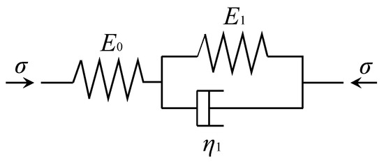
Figure 1.
The generalized Kelvin model for arch dam concrete.
In this work, in particular, the comprehensive elastic modulus inversion of arch dams can be summarized as the following fitting optimization problems:
where is the objective function of the inversion analysis of parameter and ; m is the total number of monitoring points; n is the number of monitoring times; is the weight of every monitoring value, which is often set to 1; and and are the j-th calculation value and the monitoring value of the hydraulic component separated from the monitoring deformation of the monitoring point, respectively.
The linear expansion coefficient inversion of arch dams can be summarized as the following fitting optimization problems:
where is the objective function of inversion analysis of parameter ; and are the j-th calculation value and the monitoring value of the temporal component separated from the monitoring deformation of the monitoring point, respectively.
The creep parameter inversion of arch dams can be summarized as the following fitting optimization problems:
where is the objective function of inversion analysis of parameter ; and are the j-th calculation value and the monitoring value of the time effect component separated from the monitoring deformation of the monitoring point, respectively; and is the feasible computational domain.
The above optimization problems can be solved by applying the optimization algorithm, and the parameters calculated corresponding to the smallest value of the above optimization objective functions are the inversion results.
2.1.3. Basic Deformation of Arch Dam Calculation
According to the inversion results, the basic deformation of arch dams can be calculated by using an FEM simulation. According to [K] and Equation (5), the hydraulic component of the deformation of arch dam elemental nodes can be simulated. On account of the temperature load, the temperature deformation of each node is equal to the deformation caused by the body force and the surface force. The equilibrium equation used in temperature deformation calculation is
where is the column vector of the temperature deformation and is the column vector of the temperature load of each node.
The column vector of the temperature load of each node can be demonstrated as
where is the elastic modulus of the arch dam; is the linear expansion factor; is the Poisson ratio; and is the element shape function. Consequently, the temperature deformation of each node can be simulated on the basis of the temperature variation field obtained by the FEM simulation. Because the temperature load generates only positive strain, the matrix in Equation (17) is used to guarantee only the generation of normal stress.
The FEM simulation of time effect component of dam deformation should be considered from the construction period, and because of the complex loads, it is necessary to introduce the initial strain increment method to calculate the time effect deformation.
When grading the multiple external loads and loading each level of loads, the upper level of the viscous strain of the dam and the rock foundation can be regarded as the initial strain. The nonlinear incremental constitutive relation can be expressed as
where is the stress increment, ; is strain increment, ; is viscous strain increment; and is the elastic matrix.
The basic equilibrium equation of the incremental initial strain method can be described as
where is the column vector of the increment of load of one grade; is the column vector of the deformation of one element node; and is the column vector of the equivalent node load of the initial strain.
Given the little variation of the Poisson ratio of the dam body and its foundation concrete materials over time, the Poisson ratio of viscous deformation could be replaced by the Poisson ratio of elastic deformation. For , it is assumed that stress remained virtually unchanged in . Therefore, the increment of viscous strain of generalized Kelvin modal is
where and are the elastic shear modulus and the viscosity coefficient of materials of the generalized Kelvin modal, respectively, and [C] is the matrix of the Poisson ratio .
According to the inversion results of the main parameters, the basic arch dam deformation m(x) of each point at each time can be calculated by using the FEM simulation. Obviously, the arch dam deformation field can be constructed as a calculation result.
2.2. Ordinary Kriging Interpolation Method for Spatial Variance Deformation of Arch Dams
In order to take the relationship between the points in adjacent area into account, the spatial interpolation method, which factors in the spatial correlations, can be introduced to estimate the spatial variance deformation of arch dams.
However, the deformation magnitude is different in various regions of arch dams, which is caused by the inhomogeneity of the dam materials and the boundary. The spatial variance deformation of arch dams fails to meet the second-order stationarity assumption. Therefore, the ordinary kriging interpolation method cannot be directly used, and the spatial variation characteristic of dam deformation needs to be analyzed further [31].
2.2.1. Spatial Variation Characteristic of Arch Dam Deformation Analysis
The dam material inhomogeneity is discussed below as an example to study the perturbation of deformation caused by material differences. To simplify the problem, the arch dam is approximated as consisting of a series of cantilever beams with variable sections, as shown in Figure 2.
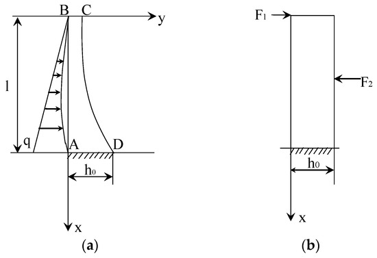
Figure 2.
The schematic diagram of cantilever beam of arch dams: (a) cantilever beam with variable sections; (b) cantilever beam with uniform sections.
As shown in Figure 2a, the load on the vertical cantilever beam of the arch dam can be expressed as a power series polynomial in head H. According to the differential relationship, the variable-section cantilever beam subjected to the load can be simplified to a uniform-section cantilever beam subjected to two concentrated forces, which is shown in Figure 2b. The deflection curve equation can be demonstrated as
where is the left concentrated force of the dam body; is the right concentrated force of the dam body; E denotes the elastic modulus of the dam body; I demonstrates the moment of the inertia of the dam section for the neutral axis; l is the height of the dam body; and x is the vertical coordinate.
In the case of estimating the continuous materials of arch dams, the elastic modulus can be described as Er, the average value of variable is 0, and the deformation of point and point can be described as
In the case of estimating the discontinuous materials of arch dams, the elastic modulus can be described as , the average value of variable is 0, and the deformation of point and point can be demonstrated as
If , then
If , according to the above analysis results, then it can be recognized that the variable meets the requirement of the second-order stationarity assumption, which means that the distribution laws of two random variables with k-dimensional vectors and are the same.
In addition, the increment of the variable meets the following two conditions:
- (1)
- In the whole study domain, the mathematical expectation of increment of random function is 0:
- (2)
- The variance function of increment of all the vectors exists and is stable:where is variation function of .
The estimation value of is , which can be expressed as
where represents the number of the experimental data pair, which is separated by vector h.
Therefore, meets the requirement of the intrinsic hypothesis. The ordinary kriging interpolation method can be introduced to estimate the of each known point of arch dams. After estimating the of the unmonitored points according to the of the known points and calculating the basic deformation m(x), the random spatial deformation of the unmonitored points can be described as follows:
Consequently, it is necessary to estimate by using the ordinary kriging interpolation method.
2.2.2. Estimation of Variable
In order to estimate the of each point of arch dams, the Monte Carlo stochastic FEM is used to obtain several groups of samples of ,which can be applied in calculating the theoretical variogram model of .
- (1)
- The calculation of the samples of variable is based on the Monte Carlo stochastic FEM [32].
The reasons behind the results of the spatial variance deformation of arch dams mainly include the discontinuous materials of the dam body and the dam foundation, the initial strain caused by pouring, the arch closure, the temperature control, the random microcracks of arch dam and uneven uplift pressure, and so on. The above reasons can be regarded as variables that follow definite distribution law and can be used to generate an arch deformation field under different situations on the basis of using the Monte Carlo stochastic FEM. First, the interval can be divided into N nonoverlapping subintervals by using the Latin hypercube sampling method. On this basis, in interval [0, 1], N random numbers can be generated after separately completing equal probability sampling in every subinterval. The random number in the n-th subinterval is
where U is a uniform random number in interval [0, 1].
After the above computational analysis, the random numbers in each subinterval are transformed into sample values by using the transformation method. In the sampling simulation, N values of each input sample xk are associated with a random sequence of integers representing the integers 1, 2, …, N, and each input sample is then substituted into an FEM simulation to obtain a number of the output samples of the arch dam deformation field corresponding to each input sample.
On the basis of one of the sets of deformation field calculation results, the deformation of each point is sampled, and the corresponding basic deformation of the point is calculated. Next, a group sample of can be calculated as follows:
Repeating the above steps will eventually result in several sets of samples of .
- (2)
- The variation function calculation of variable when the spatial point varies on the x-axis, half of the variance of the difference between the value of the variable at x and x + h is defined as the variance function of in the direction of the x-axis. This is denoted as , and the expression is as follow:
Under the hypothesis of the second-order stationarity, the following equation stands:
When the variance function is independent of x but only related to the distance h between two sample points, the following equation stands:
On the basis of the solved distance of samples and semivariance, the variation function of the variation curve can be fitted, which reflects the relationship between the value of the variation function and the certain lag distance h. In Figure 3, is the ‘nugget’ of , which means the monitoring errors and the short distance are unknown or constitute random spatial variation. is the block gold effect, which indicates the fluctuation of the variables between two points when h is very small. a is the variation range. When , the correlation of the variable values between any two points decreases as h becomes larger. In addition, when , the correlation no longer appears. a reflects the range of influence. is the total abutment value, which reflects the intensity of the variation of a regionalized variable in the study area. When , the value of can be calculated as follows:
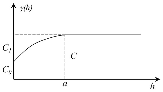
Figure 3.
The curve of variation function.
Commonly used theoretical models include the spherical model, which can be expressed as follows [33]:
In practice, is more complex and has a certain probability of being anisotropic or containing multiple levels of variability at different scales in the same direction. This anisotropy of regionalized variables can be characterized by using a nested structure, which is a combination of variability that appears to simultaneously act at different distances h and in different directions .
The nested structure can be expressed as the sum of multiple variance functions, each of which represents a variability at a particular scale, and the expression of the nested structure is
Consequently, the best linear and unbiased estimate of at a set of unmonitored points can be performed by using a known set of data that is based on the ordinary kriging interpolation algorithm.
Assume that the estimation of any block V is . This estimation is a linear combination of n information values in the estimated neighborhood, which is demonstrated as follows:
In order to obtain an unbiased estimation under the second-order stationarity assumption, it is required that .
The equation group of the ordinary kriging interpolation method is obtained as follows:
where is the semivariogram of and ; is the Lagrangian multiplier with the minimum variance; is the semivariogram of and ; and is the location of the point that needs to be estimated.
The matrix form of the above equation group is written as
where
According to Equations (42) and (43), the weight coefficients can be calculated, then the estimation value of any block segment V can be calculated by using Equation (40), and the spatial variance deformation at any point can be estimated by using Equation (31). After calculating the value of the basic deformation mk at the corresponding point, the estimation value of the dam deformation at each point can finally be obtained.
2.3. Process of the Arch Dam Deformation Field Estimation
Figure 4 demonstrates the process of the arch dam deformation field estimation on the basis of using the proposed method. The arch dam deformation field estimation steps of applying the ordinary kriging interpolation method, combined with FEM, can be implemented as follows:
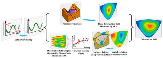
Figure 4.
Process of the arch dam deformation field estimation.
- (1)
- Preprocessing the original deformation monitoring data of arch dam and obtaining valid deformation monitoring data by using outlier detection and missing data processing.
- (2)
- Inverse analyzing the arch dam materials and mechanic parameters by using valid data.
- (3)
- Calculating arch dam basic deformation field on the basis of using the FEM.
- (4)
- Simulating deformation field samples by factoring in the discontinuity of materials, pouring, and damage to the dam on the basis of using the Monte Carlo stochastic FEM.
- (5)
- Constructing the variation model of variable and estimating the value of at each point of arch dam by using the ordinary kriging interpolation method.
- (6)
- Estimating spatial variance deformation at each point of the arch dam.
- (7)
- Adding the basic deformation and spatial variance deformation at each point of arch dam, then finishing the arch dam deformation field estimation.
3. Case Study
3.1. Brief Introduction to a Superhigh Arch Dam and Settlement of Its Deformation Monitoring Points
In recent decades, China has built a number of arch dams in the southwest of the country. Among them, the height of the Jinping superhigh arch dam is 305 m. It is currently the highest double-curvature arch dam in the world. The location of the Jinping arch dam is shown in the topographic map in Figure 5b.
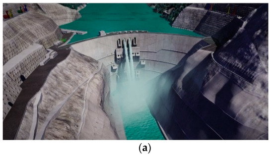
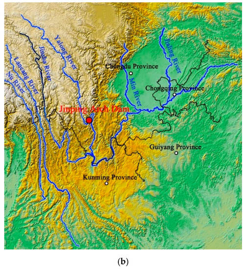
Figure 5.
Aerial view and layout of the arch dam: (a) aerial view of the Jinping arch dam; (b) the location of the Jinping arch dam.
The automatic dam structural health monitoring (SHM) system of the Jinping arch dam was completed at the end of 2015. Dam deformation is an essential and intuitive monitoring item to reflect dam structural service characteristics, especially for super-high arch dams. A plumb line (PL) system is the most popular dam deformation monitoring technique for arch dams. The automatic structural monitoring system of the Jinping super-high arch dam was completed and began to operate at the end of 2015. Dam deformation is a key monitoring item that reflects the dam structural operating characteristics, especially for super-high arch dams.
At the elevations of 1601 m, 1664 m, 1730 m, 1778 m, and 1829 m, 34 deformation monitoring points of PL systems were arranged, which are used to monitor the deformation of the dam body. Figure 6 shows the layout of the PL systems of the Jinping arch dams.
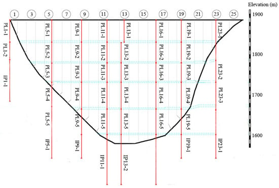
Figure 6.
The layout of the PL systems of the Jinping arch dams.
3.2. Numerical Case Study
3.2.1. The Design of Numerical Case
Because of the limited quality of the monitoring points of the arch dam, the spatially continuous deformation field of the arch dam cannot be directly monitored. To verify the estimation accuracy of the method proposed, it is necessary to generate several spatially continuous artificial deformation fields as sample fields. In this case, the sample deformation field is constructed by using the Monte Carlo stochastic FEM and the deterministic FEM by including the spatial inhomogeneity of the materials. Consequently, a numerical case is introduced in this study, and the sample deformation field generation process can be described as follows:
- (1)
- Simulating several deformation field samples of the arch dam by using the Monte Carlo stochastic FEM according to the statistical characteristics of the material parameter of the arch dam.
- (2)
- Calculating the variance distribution characteristic of the deformation field samples.
- (3)
- Generating more sample deformation fields of arch dams on the basis of the variance distribution characteristic.
- (4)
- Simulating the arch dam deformation field under the normal loads by using the deterministic FEM.
- (5)
- Superposing the deformation field generated in (3) and the deformation field simulated in (4) and then generating sample deformation fields.
The 3D finite element model of the Jinping arch dam is selected as the generalized model in this case, which is shown in Figure 7. The dam body and the surrounded mountain are divided into 38,537 elements. The average size of the element is 9 m, and the cell types consist of the linear hexahedral cell and trigonal cells. The model can be divided into three main parts: the dam body, the dam foundation, and the nearby mountains. The model was calculated to include 800 m from the axis of the arch dam on the left and right banks, 800 m upstream and downstream of the origin of the dam crest, 600 m below the footprint, and from the rocky slope above the crest to the height of the natural boundary. The hills to the left and right of the dam crest extend 2.5 times the upstream and downstream quadrants, respectively. The rock conditions and mound shapes on both sides of the dam were simulated after excavation.
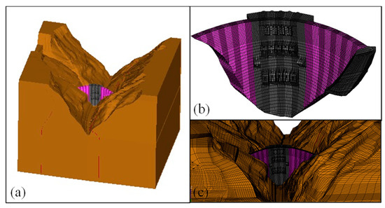
Figure 7.
The finite element model of the arch dam: (a) the dam engineering project; (b) the dam body and foundation; (c) the dam and the mountain.
The fixed constraints were imposed at the bottom of the model, and normal constraints were imposed around the perimeter. The water load was applied to the upstream dam face and the upstream reservoir area considered in the model, and the dam body and foundation adopted the linear elasticity principal structure. The actual parameters for the concrete material and the inversion parameters used in the case study are listed in Table 1.

Table 1.
Real parameters of arch dam materials and the inversion parameters.
The locations of the monitoring points in PL systems were selected as the locations of the sampling points. According to the results of the finite element numerical simulation, the basic deformation field of the arch dam can be calculated so that the basic deformation values of the monitoring points can be obtained: . On this basis, can be calculated by using the Monte Carlo stochastic FEM. Consequently, according to Equation (33), can be calculated. For one of the generated sample deformation fields, the distribution of the sample distance and semivariance of 100 samples of are shown in Figure 8.
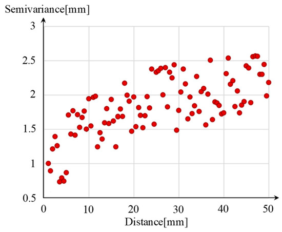
Figure 8.
Sample distance and semivariance calculation results.
After fitting the variance function five times, the function model can be obtained as
where the anisotropy ratio is and the geometric anisotropy angle is .
Once the variation function model has been established, the weight coefficients can be calculated according to the kriging equation in Equation (41), and at the unmonitored points are estimated from the known values of at the monitoring points. After obtaining the basic deformation values at the unmonitored points from the FEM simulation results, the estimated values of at the unmonitored points can be solved according to Equation (31). The estimated values of the deformation at the unmonitored points can be estimated on the basis of the estimated values of and at the unmonitored points and according to the deformation of other known points.
3.2.2. Analysis of the Estimation Results of Arch Dam Sample Deformation Fields
The simulation of the FEM selects the mean value of the parameter samples as parameters, and the simulation results of arch dam deformation fields are demonstrated in Figure 9. The deformation fields of the arch dam are estimated on the basis of 10 groups of the arch dam radial and tangential sample deformation fields and by using the ordinary kriging method, the universal kriging interpolation, and the proposed method. The radial deformation fields and tangential deformation fields of one group are illustrated in Figure 10 and Figure 11, respectively. It can be seen that simulation results of arch dam deformation fields based on FEM apparently vary from the radial and tangential sample deformation fields illustrated in Figure 10a and Figure 11a. The rest of the groups have similar results.

Figure 9.
Deformation field simulation results, based on deterministic FEM: (a) radial deformation; (b) tangential deformation.
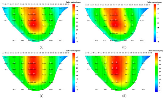
Figure 10.
One radial sample deformation field and its estimation results: (a) sample deformation field; (b) deformation field estimated on the basis of the proposed method; (c) deformation field estimated on the basis of the ordinary kriging interpolation method; (d) deformation field estimated on the basis of the universal kriging interpolation method.
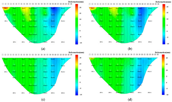
Figure 11.
One tangential sample deformation field and its estimation results: (a) sample deformation field; (b) deformation field estimated on the basis of the proposed method; (c) deformation field estimated on the basis of the ordinary kriging interpolation method; (d) deformation field estimated on the basis of the universal kriging interpolation method.
It can be observed that the variation of the deformation field simulated by using the deterministic FEM is pretty uniform, but the variation of the sample deformation field is fluctuant because of the spatial inhomogeneity of the materials. However, the deformation fields calculated by using the deterministic FEM and the sample deformation field have fairly similar basic spatial distribution characteristics. Therefore, given the spatial inhomogeneity of the arch dam materials, the deformation field of the deterministic FEM cannot completely coincide with the sample deformation fields.
3.2.3. Comparison Analysis of Numerical Deformation Field Estimation Results
As can be observed from Figure 10 and Figure 11, the deformation fields estimated by the proposed method are extremely similar to those of the sample deformation field, and the variation of the deformation fields estimated according to the proposed method is essentially the same as that of the sample deformation fields. Although the ordinary kriging interpolation method has relatively stable estimation accuracy at points near the sampling points, it does not work well when it is used to estimate the deformation at points far from the sampling points. Owing to the limited number of sampling points, the trend surface of the universal kriging interpolation does not describe the actual trend surface of the sample deformation field. As a result, the deformation field estimates from the ordinary kriging interpolation method significantly differ from the sample deformation fields and cannot describe the actual deformation characteristics of the arch dam.
In order to quantify the estimation precisions of the above methods, the mean absolute error (MAE) is introduced to analyze the errors at all points of the sample deformation fields . The MAE of one group of the deformation estimation results can be expressed as
where represents the deformation at of sample deformation field j; indicates the estimation result of the arch dam deformation at node of sample deformation field j; and represents the number of points, in this case. Therefore, a comprehensive index that factors in the 10 groups of deformation field estimation results can be defined as
where AMAE means the average value of MAE(Aj)(j = 1,2,…,10).
The MAE(Aj) and AMAE of the above methods are illustrated in Figure 12. The comparison results show that the proposed method achieves a higher estimation precision, and the AMAE values of the 10 groups of radial deformation fields and those of the tangential deformation fields are 1.977 mm and 1.654 mm, respectively. Meanwhile, the MAE(Aj) of the estimation results of radial and tangential deformation fields are much lower than the estimation results of the ordinary kriging method and the universal kriging interpolation method.
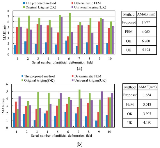
Figure 12.
Error analysis of different methods: (a) radial deformation field; (b) tangential deformation field.
3.3. Accuracy Verification Based on the Actual Monitoring Data
The monitoring deformation values of all the monitoring points of 3 typical days in 2018 were selected to verify the estimation accuracy and robustness of the proposed method. Here, 3 typical days consist of a day with a low water level and a high temperature (12 June 2018, 1801.19 m, 15.60 °C), a day with a high water level and a high temperature (4 August 2018, 1879.70 m, 17.60 °C), and a day with a high water level and a low temperature (16 December 2018, 1878.83 m, 5.4 °C). Given that the actual monitoring data of the monitoring points are discrete in space, this provides an idea to introduce the cross-validation method to compare the estimation accuracy of the proposed method, the ordinary kriging method, and the universal kriging algorithm. The basic ideas are as follows:
- (1)
- Individually remove the monitoring values of all the monitoring points in order.
- (2)
- Estimate the value of at each removed monitoring point on the basis of the remaining monitoring values by using the above three methods (n is the number of monitoring points).
- (3)
- Repeat the above operations for each monitoring point by using different methods.
- (4)
- Calculate the estimation error between the original data and the estimated value of each monitoring point.
The RMSE can be calculated according to Equation (50) to verify the precision of the interpolation. At the same time, the correlation degree can be assessed by using the coefficient R2. The calculation function is shown in Equation (51). The stronger the correlation between the two values is, the more accurate the value of R2 is.
In Equation (51), and represent the sum of the squared residuals and the total sum of squares, respectively. The calculation equations are as follows:
where is the average value of the monitoring deformation values of the sample points.
The cross-validation results of the three methods are shown in Table 2 and Table 3. The following conclusions can be drawn:

Table 2.
Cross-validation results of arch dam radial deformation fields.

Table 3.
Cross-validation results of arch dam tangential deformation fields.
- (1)
- The values of RMSE of the proposed method at different times are less than the value of other methods, and the R2 of the proposed method is higher than the R2 of other methods.
- (2)
- Regardless of the time, the deformation field estimation results of the proposed method are more accurate than the estimation results of other methods. It is more useful for the analysis of the whole deformation trend of the arch dam.
- (3)
- According to the results of the methods, R2 is basically consistent at different times, which illustrates that the proposed method has high stability and that the estimation results are accurate.
It can be seen that the RMSE of the proposed method at any time is smaller than the other two methods, and the R2 is larger than that of the other two methods. The MAE values of the radial deformation and that of the tangential deformation of the proposed method are 1.582 mm and 0.963 mm, respectively. They are both much lower than those of the ordinary kriging method (6.161 mm and 3.635 mm) and those of the universal kriging (5.162 mm and 2.401 mm) interpolation method. For monitoring points with other sampling points in the neighborhood (e.g., PL11-2 and PL19-2), the precision of the proposed method and that of the universal kriging interpolation method are higher than that of the ordinary kriging interpolation method. This is mostly because the trend surface of the universal kriging interpolation method is to a certain extent able to reflect the basic deformation characteristic of the arch dam. On the contrary, for the monitoring points where there are no monitoring points near them (e.g., PL1-1, PL23-1), the proposed method performs better than the other two methods, which primarily results from the inclusion of the physical significance of the dam deformation in the proposed method.
Figure 13 and Figure 14 show the estimation results of radial and tangential arch dam deformation fields on 12 June 2018 based on the above methods, respectively. It can be found that the deformation fields estimated on the basis of the ordinary kriging method and the universal kriging interpolation method do not agree with those simulated by using the FEM in some regions of the arch dam. In summary, the practical application shows that the proposed method accurately estimates the arch dam deformation fields.


Figure 13.
The estimation results of radial arch dam deformation fields, based on (a) the FEM; (b) the proposed method; (c) the ordinary kriging interpolation method; (d) the universal kriging interpolation method.
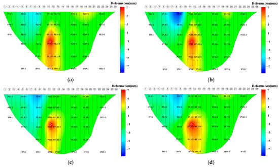
Figure 14.
The estimation results of tangential arch dam deformation fields, based on (a) the FEM; (b) the proposed method; (c) the ordinary kriging interpolation method; (d) the universal kriging interpolation method.
However, the estimation errors of the ordinary kriging method and universal kriging interpolation method are small at the location close to the monitoring points, and the errors are large at the location away from the monitoring points. The error range of the radial deformation of the universal kriging method and the ordinary kriging interpolation method are both pretty large. Because the proposed method factors in the advantages of the FEM with the ordinary kriging interpolation method, the error range of the radial deformation estimation results is from 0.755 mm to 3.458 mm. The error range of the tangential deformation estimation results is from 0.560 mm to 1.531 mm.
4. Conclusions
Current data-based deformation field estimation methods and the FEM encounter difficulty in trying to accurately estimate arch dam deformation field. This study proposes combining the ordinary kriging interpolation method with the FEM to create the arch dam deformation field estimation method, which is supposed to be successfully applied to the determination of arch dam spatial deformation characteristics. The performance of the proposed method is tested through a numerical case study and the engineering application of the Jinping superhigh arch dam. Some conclusions can be drawn, as follows:
- (1)
- The estimation result of the proposed method in this paper is based on the FEM simulation result, which is rich with data and has low precision. After merging the ordinary kriging interpolation results, the precision of the arch dam deformation estimation has been effectively improved. Compared with the kriging-based method, this method is more stable and has higher estimation accuracy.
- (2)
- Sufficient and valid monitoring data help to ensure the validity of the arch deformation field estimation results of the proposed method.
- (3)
- The effect of inhomogeneous material properties on arch dam deformation is reflected by 10 sample deformation fields; the uneven dam deformation caused by material inhomogeneity leads to errors in the arch dam deformation field simulation results of the FEM. The errors of the ordinary kriging method and the universal kriging interpolation method come from their failing to sufficiently account for and inaccurately calculating the physical insignificance of the arch dam deformation field.
The method proposed in this paper is able to also estimate the temperature or stress field of the arch dam on the basis of using valid monitoring data. The estimation effects of the above fields based on the proposed method also need to be further verified.
Author Contributions
C.S.: methodology, software, investigation, writing—original draft, validation. Y.X.: data curation, writing—original draft. H.C.: supervision, writing—review and editing. S.Z.: supervision, validation, writing-review and editing. X.Q.: writing—review and editing. All authors have read and agreed to the published version of the manuscript.
Funding
This paper received funding from the Fundamental Research Funds for the Central Universities (B220201042), National Natural Science Foundation of China (52209159,U2243223), Water Conservancy Science and Technology Project of Jiangsu (2022024), Jiangsu Young Science and Technological Talents Support Project (TJ-2022-076).
Data Availability Statement
The data presented in this study are available on request from the corresponding author.
Acknowledgments
The support of Hohai University, China, is gratefully acknowledged.
Conflicts of Interest
The authors declare no conflict of interest.
References
- Shao, C.; Zheng, S.; Gu, C.; Hu, Y.; Qin, X. A novel outlier detection method for monitoring data in dam engineering. Expert Syst. Appl. 2022, 193, 116476. [Google Scholar] [CrossRef]
- Xu, D.; Dong, L.; Borana, L.; Liu, H. Early-warning system with quasi-distributed fiber optic sensor networks and cloud computing for soil slopes. IEEE Access 2017, 5, 25437–25444. [Google Scholar] [CrossRef]
- Su, H.; Yan, X.; Liu, H.; Wen, Z. Integrated multi-level control value and variation trend early-warning approach for deformation safety of arch dam. Water Resour. Manag. 2017, 31, 2025–2045. [Google Scholar] [CrossRef]
- Liu, W.; Pan, J.; Ren, Y.; Wu, Z.; Wang, J. Coupling prediction model for long-term displacements of arch dams based on long short-term memory network. Struct. Control Health Monit. 2020, 27, e2548. [Google Scholar] [CrossRef]
- Zheng, S.; Shao, C.; Gu, C.; Xu, Y. An automatic data process line identification method for dam safety monitoring data outlier detection. Struct. Control Health Monit. 2022, 29, e2948. [Google Scholar] [CrossRef]
- Xiao, H.; Zhang, Z.; Chen, L.; He, Q. An improved spatio-temporal kriging interpolation algorithm and its application in slope. IEEE Access 2022, 8, 90718–90729. [Google Scholar] [CrossRef]
- Salazar, F.; Morán, R.; Toledo, M.Á.; Oñate, E. Data-based models for the prediction of dam behaviour: A review and some methodological considerations. Arch. Comput. Methods Eng. 2017, 24, 1–21. [Google Scholar] [CrossRef]
- Xu, H.; Li, H.; Yang, X.; Qi, S.; Zhou, J. Integration of terrestrial laser scanning and nurbs modeling for the deformation monitoring of an earth-rock dam. Sensors 2018, 19, 22. [Google Scholar] [CrossRef]
- Xiang, X.; Chen, J.; Wang, H.; Pei, L.; Wu, Z. PS selection method for and application to GB-SAR monitoring of dam deformation. Adv. Civ. Eng. 2019, 2019, 8320351. [Google Scholar] [CrossRef]
- Scaioni, M.; Marsella, M.; Crosetto, M.; Tornatore, V.; Wang, J. Geodetic and remote-sensing sensors for dam deformation monitoring. Sensors 2018, 18, 3682. [Google Scholar] [CrossRef]
- Anchuela, Ó.P.; Frongia, P.; Di Gregorio, F.; Sainz, A.C.; Juan, A.P. Internal characterization of embankment dams using ground penetrating radar (GPR) and thermographic analysis: A case study of the Medau Zirimilis Dam (Sardinia, Italy). Eng. Geol. 2018, 237, 129–139. [Google Scholar] [CrossRef]
- Yang, H.; Li, T.; Zhang, Z. Application of metabolic model in slope displacement monitoring by Lagrange interpolation method. Saf. Environ. Eng. 2017, 24, 33–38. [Google Scholar]
- Wen, H.; Yang, P. Application of GM (1, 1) model based on Hermite interpolation method in prediction of soft foundation surface subsidence. Port Wat. Eng. 2015, 3, 47–51. [Google Scholar]
- Liu, Y.; Duan, Y.; Guan, L. Cubic spline interpolation method and its application in deformation data preprocessing. Site Investig. Sci. Technol. 2017, 6, 47–50. [Google Scholar]
- Nicklow, J.; Reed, P.; Savic, D.; Dessalegne, T.; Harrell, L.; Chan-Hilton, A.; Karamouz, M.; Minsker, B.; Ostfeld, A.; Singh, A.; et al. State of the art for genetic algorithms and beyond in water resources planning and management. J. Water Resour. Plann. Manag. 2010, 136, 412–432. [Google Scholar] [CrossRef]
- Moral, F.J. Comparison of different geostatistical approaches to map climate variables: Application to precipitation. Int. J. Climatol. 2010, 30, 620–631. [Google Scholar] [CrossRef]
- Delbari, M.; Afrasiab, P.; Jahani, S. Spatial interpolation of monthly and annual rainfall in northeast of Iran. Meteorol. Atmos. Phys. 2013, 122, 103–113. [Google Scholar] [CrossRef]
- Abo-Monasar, A.; Al-Zahrani, M.A. Estimation of rainfall distribution for the southwestern region of Saudi Arabia. Hydrol. Sci. J. 2014, 59, 420–431. [Google Scholar] [CrossRef]
- Goovaerts, P. Geostatistical approaches for incorporating elevation into the spatial interpolation of rainfall. J. Hydrol. 2000, 228, 113–129. [Google Scholar] [CrossRef]
- Feki, H.; Slimani, M.; Cudennec, C. Incorporating elevation in rainfall interpolation in Tunisia using geostatistical methods. Hydrol. Sci. J. 2012, 57, 1294–1314. [Google Scholar] [CrossRef]
- Chen, C.; Lu, X.; Li, J.; Chen, J.; Zhou, Z.; Pei, L. A novel settlement forecasting model for rockfill dams based on physical causes. Bull. Eng. Geol. Environ. 2021, 80, 7973–7988. [Google Scholar] [CrossRef]
- Guo, Q.; Pei, L.; Zhou, Z.; Chen, J.; Yao, F. Response surface and genetic method of deformation back analysis for high core rockfill dams. Comput. Geotech. 2016, 74, 132–140. [Google Scholar] [CrossRef]
- Jia, Y.; Xu, B.; Chi, S.; Xiang, B.; Xiao, D.; Zhou, Y. Joint back analysis of the creep deformation and wetting deformation parameters of soil used in the Guanyinyan composite dam. Comput. Geotech. 2018, 96, 167–177. [Google Scholar] [CrossRef]
- Wen, L.; Chai, J.; Xu, Z.; Qin, Y.; Li, Y. A statistical review of the behaviour of concrete-face rockfill dams based on case histories. Géotechnique 2018, 68, 749–771. [Google Scholar] [CrossRef]
- Tan, X.; Wang, X.; Khoshnevisan, S.; Hou, X.; Zha, F. Seepage analysis of earth dams considering spatial variability of hydraulic parameters. Eng. Geol. 2017, 228, 260–269. [Google Scholar] [CrossRef]
- Mouyeaux, A.; Carvajal, C.; Bressolette, P.; Peyras, L.; Breul, P.; Bacconnet, C. Probabilistic analysis of pore water pressures of an earth dam using a random finite element approach based on field data. Eng. Geol. 2019, 259, 105190. [Google Scholar] [CrossRef]
- Chen, H.; Liu, D. Stochastic finite element analysis of rockfill dam considering spatial variability of dam material porosity. Eng. Comput. 2019, 36, 2929–2959. [Google Scholar] [CrossRef]
- Yang, H.; Zhang, L.; Pan, Q.; Phoon, K.K.; Shen, Z. Bayesian estimation of spatially varying soil parameters with spatiotemporal monitoring data. Acta Geotech. 2021, 16, 263–278. [Google Scholar] [CrossRef]
- Jiang, S.; Wang, L.; Ouyang, S.; Huang, J.; Liu, Y. A comparative study of Bayesian inverse analyses of spatially varying soil parameters for slope reliability updating. Georisk Assess. Manag. Risk Eng. Syst. Geohazards 2022, 16, 746–765. [Google Scholar] [CrossRef]
- Bogaert, P. Comparison of kriging techniques in a space-time context. Math. Geol. 1996, 28, 73–86. [Google Scholar] [CrossRef]
- Matheron, G. Traité de Géostatistique Appliquée. 1; Editions Technip: Paris, France, 1962. [Google Scholar]
- Zhang, Y.; Tu, B.; Wang, H. Application of stochastic finite element method in the numerical analysis of historical masonry buildings. Sichuan Build. Sci. 2016, 42, 6–10, (In Chinese with English Abstract). [Google Scholar]
- Tziachris, P.; Metaxa, E.; Papadopoulos, F.; Papadopoulou, M. Spatial Modelling and Prediction Assessment of Soil Iron Using Kriging Interpolation with pH as Auxiliary Information. ISPRS Int. J. Geo-Inf. 2017, 6, 283. [Google Scholar] [CrossRef]
Disclaimer/Publisher’s Note: The statements, opinions and data contained in all publications are solely those of the individual author(s) and contributor(s) and not of MDPI and/or the editor(s). MDPI and/or the editor(s) disclaim responsibility for any injury to people or property resulting from any ideas, methods, instructions or products referred to in the content. |
© 2023 by the authors. Licensee MDPI, Basel, Switzerland. This article is an open access article distributed under the terms and conditions of the Creative Commons Attribution (CC BY) license (https://creativecommons.org/licenses/by/4.0/).