Abstract
Full-duplex (FD) communication has been shown to provide an increased achievable rate,
while millimeter wave (mmWave) communications benefit from a large available bandwidth that
further improves the achievable rate. On the other hand, the concept of multi-set space-time shift
keying (MS-STSK) has been proposed to provide a flexible design trade-off between throughput
and performance. Hence, in this work, we consider the design of an FD-aided MS-STSK transceiver
for millimeter wave communications. However, a major challenge is that channel reciprocity is not
valid in mmWave communications due to shorter channel coherence time. Thus, the uplink (UL)
pilots cannot be utilized to estimate the downlink (DL) channel. To overcome this challenge, we
propose a beamforming technique based on channel statistics without assuming channel reciprocity.
For this purpose, a closed-form expression for the outage probability of the system is derived by
employing the characterization of the ratio of the Indefinite Quadratic Form (IQF). The derived
analytical expression is then utilized to design optimum beamforming weights using the Sequential
Quadratic Programming (SQP)-based heuristic method. Moreover, an Iterative Statistical Method
(ISM) of joint transmit and receive beamforming algorithm is also developed by utilizing Principle
Eigenvector (PE) and Generalized Rayleigh Quotient (G-RQ) optimization techniques. Finally, we
verify our simulation results with the theoretical analysis.
Keywords:
full-duplex; multi-set space–time shift keying; millimeter wave; outage probability; statistical beamforming MSC:
94A05
1. Introduction
Due to the increasing demand for larger data rates and lower latency, the next generation of wireless communication is looking for enhanced spectral efficiency with better latency performance [1]. Millimeter wave-based communications inherit a large available bandwidth ranging from 28 to 300 GHz and hence are capable of delivering higher data rates with larger coverage [2]. However, the performance of mmWave-based frequency systems is highly sensitive to atmospheric and weather conditions that result in higher propagation losses [2]. Hence, directional transmission is employed to mitigate the propagation losses, where large antenna arrays can be used for achieving beamforming gains [3,4].
Multiple-In-Multiple-Output (MIMO) systems have been shown to provide beneficial throughput and performance gains [5]. The concept of spatial modulation (SM) was proposed as a low-complexity MIMO design option for providing an improved performance versus complexity trade-off by potentially relying on a single RF chain [6,7]. Recently, the idea of space–time shift keying (STSK) was introduced to provide a more flexible transmission scheme versus conventional multiplexing gain design adjustments [8]. In STSK, the transmitting signal is spread over multiple time slots and transmit antennas using certain dispersion matrices. It was shown in [9] that the STSK scheme can improve the Bit Error Rate (BER) and throughput of the system. Additionally, the idea of STSK was further enhanced in [10] by incorporating both SM and STSK to come up with the method of multi-set STSK (MS-STSK). This scheme is capable of transmitting information by utilizing the indices of the complex-valued signal, the dispersion matrices, and the index of the antenna combination.
Despite the above advantages of the mmWave and the MS-STSK systems, the performance of these systems is highly affected by self-interference (SI). Therefore, in addition to the traditional SI suppression strategies, the SI cancellation relying on beamforming techniques is critical at mmWave frequency. On the other hand, the use of pilots increases the overhead, resulting in a lower spectral efficiency. This work aims to tackle these issues.
This paper is structured as follows. The literature review is presented in Section 2 after the introduction in Section 1. Next, the system model for the MS-STSK-based FD mmWave communication system is presented in Section 3. The derivation of outage probability is provided in Section 4. Our suggested statistical techniques for concurrently developing the transmit and receive beamformer weights are developed in Section 5. Simulation results are presented in Section 6. Finally, Section 7 provides concluding observations.
2. Literature Review
Due to the substantial self-interference that comes from the transmitter’s own transmission interfering with the received signal, the idea of simultaneous transmission and receiving in the same frequency band was deemed impracticable. However, it was shown in [11,12] that this is possible and it is termed full-duplex (FD) wireless communication. Hence, it can achieve twice the spectral efficiency in contrast to the conventional half-duplex communication, which was a great breakthrough [13,14,15].
Designing an FD mmWave communication system is a promising research direction for further improving the achievable rate as well as supporting a large number of users [16]. It was shown in [16] that careful beamforming design for FD mmWave systems can provide clear performance gains. Then, several works in the literature have been devoted to the design of transmit and receive beamforming techniques in FD and mmWave communication [17,18,19,20,21,22,23,24,25,26,27,28,29,30,31,32]. A summary of these works with their approaches and shortcomings is provided in Table 1.

Table 1.
Summary of Literature Review.
2.1. Shortcomings in the Existing Works
The advantages of both the FD and the MSTSK techniques motivated us to deploy these at mmWaves in order to further enhance spectral efficiency. However, efficient beamforming in such a system has not been investigated in the existing works. Additionally, it is observed that most of the existing beamforming techniques are based on either perfect or imperfect Channel State Information (CSI) estimation requiring pilot transmission. This is usually completed with the assumption that channel reciprocity holds as long as the UL and the DL transmission occur within a channel’s coherence time. Thus, the base station (BS) can utilize that same CSI, which was obtained in UL transmission. However, the assumption of channel reciprocity is not valid in mmWave communications as the channel coherence time is very short [33], and thus, the UL CSI can not be utilized for the DL transmission. On the other hand, CSI estimation by the separate DL pilot transmission results in a larger overhead [34]. To overcome these challenges, we propose beamforming design relying only on channel statistics rather than requiring channel estimation using pilot transmissions and assuming channel reciprocity. Our major contributions are listed next.
2.2. Our Contributions and Paper Organization
The following are our work’s main contributions:
- With the aid of the IQF representation, we express the Signal-to-Interference Ratio (SINR) of the users’ signal at the BS of the MS-STSK-based FD mmWave communication system as the ratio of IQFs.
- We derive the outage probability expression for individual users in the MS-STSK-based FD mmWave communication system by utilizing the characterization of IQF ratio with the aid of conditional probability evaluation.
- We formulate a constrained optimization problem to design both transmit and receive beamforming weights in the MS-STSK-based FD mmWave communication system by minimizing the scalarized sum outage probability of the system while constraining the beamformer weights power to unity.
- We created two techniques to address the proposed constrained optimization problem: the first utilizes the SQP-based heuristic optimization technique and the second employs an iterative procedure of jointly designing the transmit and the receive beamforming algorithm with the aid of the PE and the G-RQ optimization techniques.
3. System Model
In this work, an FD MS-STSK-assisted BS communicating with multiple Half-Duplex (HD) users via a point-to-point link is considered as shown in Figure 1; that is, the BS is receiving signals from a single user only at a time. The BS is equipped with and antenna arrays (AAs) for the transmit mode and the receive mode, respectively. Each User Equipment (UE) is equipped with AAs (the number of transmitter AAs can be different for UEs, which can also be different from the number of receiver AAs at the BS. However, we kept the same AAs for simplicity of presentation, while all the proposed design is valid for variable AAs also), and each AA at the BS and the UE is equipped with K antenna elements (AEs). Moreover, there are M RF chains at the BS which are linked with M active AAs out of the total of available transmit AAs at any given time, as shown in Figure 1.
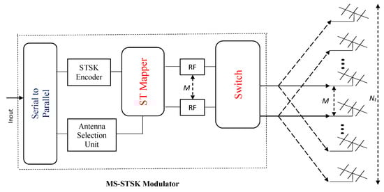
Figure 1.
Block diagram of the MS-STSK modulator.
The BS is equipped with MS-STSK encoder/decoder which is utilized to map the input bit stream in order to form an MS-STSK codeword as illustrated in Figure 1. The complex-valued amplitude-phase modulation signal, the dispersion matrix, and the indexes of the activated transmit AAs are used to transmit the information in the input data (see [10] for further details). The codeword transmitted for the APM symbol (denoted as ) by the MS-STSK encoder can be expressed as:
where is the dispersion matrix used for the transmit antenna combinations (AC).
After describing the MS-STSK system model employed at the BS, we consider the uplink signal, where a single HD UE communicates in a point-to-point link with the BS receiver using multiplexing-based MIMO transmission. Additionally, the BS is broadcasting and receiving simultaneously, since it is functioning in the FD mode, as indicated in Figure 2, which causes self-interference (SI). Thus, the received signal at the BS due to user i (denoted by ) of dimension after combining with receive combiner matrix is given by
where and are the the transmitted signal matrices of BS and user i, respectively, and are the transmit precoder matrices of BS and user i, respectively, is the noise matrix at the BS receiver whose elements are independent and identically distributed (i.i.d.) with zero mean and variance , and is the channel matrix from user i to the BS and is given by
where is the cluster sub-channel matrix of size , which is given by
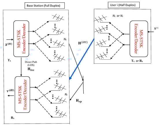
Figure 2.
Point-to-point communication between Full Duplex BS with MS-STSK modulator/ demodulator and Half-Duplex user.
Meanwhile, is the channel matrix of size in the cluster linking between the AA and the AA at the receiver and the transmitter, respectively.
The statistical model used for the channel matrix is composed of clusters with rays, which is given by
where and are the response vectors for receive and transmit AAs, respectively. In this work, we consider uniform linear AAs, for which the response vectors and are given by [35]
where and represent, respectively, the angles of arrival and departure.
The second term in (2) is the interference due to the BS’s own transmission as the BS is operating in the FD mode, where it can transmit and receive at the same time. The self-interference channel matrix at the FD BS is denoted as , which is a near-field channel and can be represented as [16,20,36]
where is the Rician factor, is the near-field channel’s line-of-sight (LOS) component, and is the reflected path of the SI channel for the BS, and it is modeled as in (4) [16]. Additionally, the entry of the LOS channel matrix denoted as is given by [16,20,36]
where constant is utilized to achieve the power normalization, that is, . Here, the distance between the transmitting AE and the receiving AE is denoted as , which can be calculated as [16,20]:
Here, D is the distance by which the AAs are separated and is the angle of AAs. In the next section, we present the outage probability analysis, which is then used for the precoder and combiner design.
4. Outage Probability Analysis
Consider the system model defined in (2) employing the SI channel in (7); then, the received signal can be stated as
Thus, the instantaneous SINR at the BS reception from the user i can be stated as
where shows the Frobenius norm of the matrix and is the expectation operator.
At this stage, we denote as the column vector in , as the column vector in , and as the column vector in . Additionally, let us denote to represent the element in , is the element in , and is the column vector in which is zero mean additive white noise having variance . Next, by using the vectorized version of the channel matrices, i.e., , , and with the aid of linear algebra property, we can express the terms , , and as follows:
where the notation ⊗ denotes the Kronecker product and is the -dimensional Identity matrix. Finally, using the whitening transformation for random channel vectors, i.e., and where and are the correlation matrices for and , respectively. Thus, the SINR given in (13) can be formulated as a ratio of IQF as follows:
where the notation denotes the weighted norm of vector and is defined as . The scalar term and the matrices and appearing in (15) are defined as
To obtain the expression (15), we have used the fact that the input signals are unit power, that is and . In addition, we have used the fact that .
Next, using the definition that the outage probability is the likelihood that the SINR is below a specific power threshold, say , we can evaluate its outage probability as follows:
Given the fact that the random vectors and are independent, we can evaluate the probability in two steps: first, evaluate the conditional outage probability of SINR conditioned on or equivalently conditioned on and then average the conditional probability over the PDF of z to evaluate the outage probability. In the first step, the conditional outage probability given z can be evaluated using the approach for characterizing the Indefinite Quadratic Forms provided in [37,38] and is given by
where is the eigenvalue of the matrix . Next, using the approach of [37], the PDF of z can be shown to be
where is the eigenvalue of the matrix . Finally, by averaging the conditional probability over using the approach of [39], the required outage probability can be expressed as
where
and
5. Design of Optimum Beamformer Weights
Here, we provide our suggested method for determining the transmit and receive beamformer weights for all users, i.e., and . Here, the objective is to develop an optimization problem that can provide the optimum beamforming solution for both the transmitter and the receiver by minimizing the outage probability for all system users. We propose to minimize the scalarized sum outage probability (denoted as ) for total users using the approach of [40]. Thus, can be stated as
In our work, the proposed objective is to minimize the sum outage probability with respect to the transmit and the receive beamforming weights of all users while constraining the powers of these beamforming weights to unity, that is,
Next, two methods to deal with the optimization problem in (23) are provided.
5.1. Heuristic Approach for Joint Optimization of Precoder and Beamformer
It can be observed that the objective function proposed in (23) is highly non-linear and non-convex in nature. Thus, a unique closed-form solution cannot be obtained using classical optimization tools. Therefore, we propose to use the sequential quadratic programming (SQP)-based solution which is a well-established technique in optimization theory [41].
5.2. Closed Form Iterative Solution
The heuristic approach presented in Section 5.1 to solve the optimization problem in (23) requires exhaustive search and hence has high computational complexity. Thus, a sub-optimal solution can be used to jointly optimize the transmit and receive beamforming weights, which has significantly reduced computational complexity. For this purpose, we develop an iterative solution that utilizes the “Principle Eigenvector” method [42] to obtain transmit beamformer weights (i.e., ) using initialized receive beamformer weights (i.e., ) and then calculate the receive beamformer weights using the “Generalized Rayleigh Quotient (G-RQ)” method [40]. This process in iterations will be continued until the sum SINR is maximized. The design details are presented in the following sections.
5.2.1. Transmit Beamforming using Principle Eigenvector Method
In order to design the transmit beamformer weights , we utilize the approach of principle eigenvector [42] to find the solution that maximizes the capacity by maximizing the SINR. To achieve this, the desired signal component is maximized while the beam powers are limited to unity. For illustration, we use the case of our presented system model in (2), where the transmit beamforming weights will be calculated using the following optimization strategy
which can be equivalently expressed as
Next, using the fact that , where is the vectorized version of , we can set up the above optimization task as
where is the correlation matrix of . The solution of the above task is well established and is given by the eigenvector that corresponds to the largest eigenvalue of matrix [42], that is,
This method of evaluating given in (26) will be repeated for all j (i.e., for all columns in ) and all i (i.e., for all users ).
5.2.2. Receive Beamforming Using G-RQ Method
In order to use the G-RQ solution for our task, let us consider the dimensional received signal vector at the BS from user i via receive AA (denoted as ), and it can be stated as
Then, the statistical SINR for the user signal at the BS via the receive AA can be expressed as
where
The G-RQ method for obtaining can be formulated using the following constrained optimization task [40]:
The solution for this constrained optimization is well known [40] and is given by
where and .
A pseudo-code for the proposed iterative statistical method (denoted as ISM) to obtain beamforming in the MS-STSK-based FD mmWave system is specified as Algorithm 1.
| Algorithm 1 Pseudo-code for the ISM algorithm. |
| Require: Set the precision level () and criteria for the algorithm’s termination.
Require: Set the time index . Compute transmit beamfomer weights using (26) to obtain . Repeat the above step for all users, that is, evaluate . Compute the receive beamformer weights using (30) to obtain . Compute the objective function, i.e, using (28). . Evaluate using (28) if then update beamforming weights. else Termination condition = true. end if |
6. Simulation Results
Here, we provide the simulation results to confirm our theoretical analysis for the MS-STSK-based FD mmWave system. For this purpose, we use MATLAB software to implement the system model defined in (2). The channel matrices and are generated using (3)–(6). Here, the angles of arrival and departure ( and ) are obtained randomly using uniform random variables in the range . The cluster size () and the number of rays () are set to unity for all m and n. The results of the simulation are calculated by averaging 400 different Monte Carlo simulations. In our experiments, we consider a total two number of users, i.e., .
First, we contrast user 1’s analytically calculated outage probability at the BS with the simulated one via Monte Carlo runs. For this purpose, the analytical outage probability is calculated using the derived expression in (20). In this particular experiment, the SNR value is kept at 20 dB. The antenna array size, the number of clusters, and the number of received antennas used are , , and , respectively. The transmit and the receive beamformer weights (i.e., and for all users (i = 1, 2) are generated randomly with complex entries. This comparison is reported in Figure 3 for three different values of the number of RF chains, that is, M = 2, M = 16, and M = 32. It can be easily depicted from the displayed results that the theoretical results match well with the simulations for all three values of M, which validates our derived analytical expressions for the outage probability.
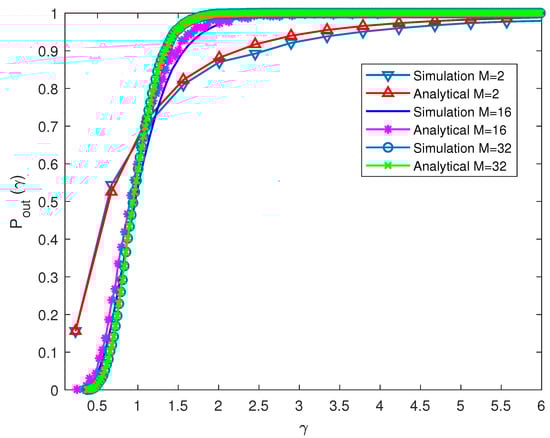
Figure 3.
Validation of analytical results for the BS outage probability due to user 1 via Monte Carlo simulations.
Next, in Figure 4, the performance of the SQP-based proposed heuristic method is compared for various values of antenna arrays K (i.e., K = 3, 5, 7). The transmit and the receive beamfomer weights are initialized with random complex values. The SQP-based proposed heuristic method is then employed to solve the constrained optimization task of (23). It is evident that the suggested SQP-based solution has reduced the likelihood of an outage. Secondly, it can be observed that the optimization gain in terms of reduction in outage probability is almost identical for all values of K. In addition, it can be observed that the outage probability reduction is significant using the designed beamforming. For example, at the threshold value of = 2.5, the outage probability for K = 3 is reduced from 0.88 to 0.78, which is significant.
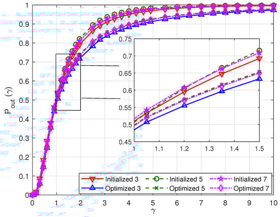
Figure 4.
Performance of the proposed SQP-based method for with and .
Finally, in Figure 5, we contrasted the proposed ISM algorithm’s performance with that of the SQP-based proposed heuristic method. For this experiment, we set the system parameters as used in Figure 3 except K = 3 and M = 16. It can be depicted from the result that both the proposed methods have minimized the outage probability as compared to the initial result. Additionally, it can be noticed that the proposed iterative ISM strategy has outperformed the proposed SQP-based heuristic approach. This may be due to the reason that the expression of outage probability is highly non-linear and non-convex, which makes it possible for the heuristic method to become trapped in a local minimum. Thus, it can be concluded that the proposed methods of beamforming design are capable of improving the system’s performance.
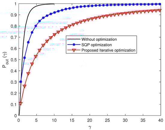
Figure 5.
Performance comparison of the sum outage probabilities for the proposed methods.
7. Conclusions
In this work, we used the characterization of the IQF ratio to obtain a closed-form formula for the outage probability in the MS-STSK-based FD mmWave communication system. Additionally, by minimizing the obtained outage probability expression, we created two statistical techniques for generating transmit and receive beamforming weights. Our theoretical analysis has been validated using simulation findings. The fact that the suggested approaches solely rely on channel data and do not require pilot broadcast for channel estimation makes them bandwidth-efficient, which is a significant advantage.
Author Contributions
Conceptualization, A.J.A., M.E.-H. and M.M.; methodology, A.J.A. and M.M.; software, A.J.A., S.X.N. and M.M.; validation, U.M.A.-S., A.J.A. and M.M.; formal analysis, A.J.A., M.E.-H. and U.M.A.-S.; investigation, S.X.N. and M.M.; resources, A.J.A. and U.M.A.-S. All authors have read and agreed to the published version of the manuscript.
Funding
This research work was funded by Institutional Fund Projects under grant No.: (IFPH: 117-135-2020). Therefore, the authors gratefully acknowledge technical and financial support from the Ministry of Education and King Abdulaziz University, DSR, Jeddah, Saudi Arabia.
Data Availability Statement
The data presented in this study are available on request from the corresponding author.
Conflicts of Interest
The authors declare no conflict of interest.
References
- Alsabah, M.; Naser, M.A.; Mahmmod, B.M.; Abdulhussain, S.H.; Eissa, M.R.; Al-Baidhani, A.; Noordin, N.K.; Sait, S.M.; Al-Utaibi, K.A.; Hashim, F. 6g wireless communications networks: A comprehensive survey. IEEE Access 2021, 9, 148191–148243. [Google Scholar] [CrossRef]
- Hemadeh, I.; Satyanarayana, K.; El-Hajjar, M.; Hanzo, L. Millimeter-wave communications: Physical channel models, design considerations, antenna constructions and link-budget. IEEE Commun. Surv. Tutor. 2018, 20, 870–913. [Google Scholar]
- MacCartney, G.R.; Samimi, M.K.; Rappaport, T.S. Exploiting directionality for millimeter-wave wireless system improvement. In Proceedings of the 2015 IEEE International Conference on Communications (ICC), London, UK, 8–12 June 2015; pp. 2416–2422. [Google Scholar]
- Satyanarayana, K.; El-Hajjar, M.; Kuo, P.H.; Mourad, A.; Hanzo, L. Dual-function hybrid beamforming and transmit diversity aided millimeter wave architecture. IEEE Trans. Veh. Technol. 2018, 67, 2798–2803. [Google Scholar] [CrossRef]
- Hanzo, L.; El-Hajjar, M.; Alamri, O. Near-capacity wireless transceivers and cooperative communications in the mimo era: Evolution of standards, waveform design, and future perspectives. Proc. IEEE 2011, 99, 1343–1385. [Google Scholar] [CrossRef]
- Ishikawa, N.; Sugiura, S.; Hanzo, L. 50 years of permutation, spatial and index modulation: From classic rf to visible light communications and data storage. IEEE Commun. Surv. Tutor. 2018, 20, 1905–1938. [Google Scholar] [CrossRef]
- Mao, T.; Wang, Q.; Wang, Z.; Chen, S. Novel index modulation techniques: A survey. IEEE Commun. Surv. Tutor. 2019, 21, 315–348. [Google Scholar] [CrossRef]
- Sugiura, S.; Chen, S.; Hanzo, L. Space-time shift keying: A unified mimo architecture. In Proceedings of the Globecom, Miami, FL, USA, 6–10 December 2010; pp. 1–5. [Google Scholar]
- Sugiura, S.; Chen, S.; Hanzo, L. Generalized space-time shift keying designed for flexible diversity-, multiplexing- and complexity-tradeoffs. IEEE Trans. Wirel. Commun. 2011, 10, 1144–1153. [Google Scholar] [CrossRef]
- Hemadeh, I.A.; El-Hajjar, M.; Won, S.; Hanzo, L. Layered multi-group steered space-time shift-keying for millimeter-wave communications. IEEE Access 2016, 4, 3708–3718. [Google Scholar] [CrossRef]
- Bharadia, D.; McMilin, E.; Katti, S. Full duplex radios. ACM SIGCOMM 2013, 43, 375–386. [Google Scholar] [CrossRef]
- Everett, E.; Duarte, M.; Dick, C.; Sabharwal, A. Empowering full-duplex wireless communication by exploiting directional diversity. In Proceedings of the 2011 Conference Record of the Forty Fifth Asilomar Conference on Signals, Systems and Computers (ASILOMAR), Pacific Grove, CA, USA, 6–9 November 2011; pp. 2002–2006. [Google Scholar]
- Duarte, M.; Sabharwal, A. Full-duplex wireless communications using off-the-shelf radios: Feasibility and first results. In Proceedings of the Asilomar Conference on Signals, Systems and Computers (ASILOMAR), Pacific Grove, CA, USA, 7–10 November 2010; pp. 1558–1562. [Google Scholar]
- Sabharwal, A.; Schniter, P.; Guo, D.; Bliss, D.W.; Rangarajan, S.; Wichman, R. In-band full-duplex wireless: Challenges and opportunities. IEEE JSAC 2014, 32, 1637–1652. [Google Scholar] [CrossRef]
- Zhang, Z.; Long, K.; Vasilakos, A.V.; Hanzo, L. Full-duplex wireless communications: Challenges, solutions, and future research directions. Proc. IEEE 2016, 104, 1369–1409. [Google Scholar] [CrossRef]
- Satyanarayana, K.; El-Hajjar, M.; Kuo, P.; Mourad, A.; Hanzo, L. Hybrid beamforming design for full-duplex millimeter wave communication. IEEE Veh. Trans. Technol. 2019, 68, 1394–1404. [Google Scholar] [CrossRef]
- Alkhateeb, A.; Heath, R.W. Frequency selective hybrid precoding for limited feedback millimeter wave systems. IEEE Trans. Commun. 2016, 64, 1801–1818. [Google Scholar] [CrossRef]
- Lin, C.T.; Tseng, F.S.; Wu, W.R. MMSE transceiver design for full-duplex MIMO relay systems. IEEE Veh. Trans. Technol. 2017, 66, 6849–6861. [Google Scholar] [CrossRef]
- Sohrabi, F.; Yu, W. Hybrid analog and digital beamforming for mmwave OFDM large-scale antenna arrays. IEEE J. Sel. Areas Commun. 2017, 35, 1432–1443. [Google Scholar] [CrossRef]
- Liu, X.; Xiao, Z.; Bai, L.; Choi, J.; Xia, P.; Xia, X. Beamforming based full-duplex for millimeter-wave communication. Sensors 2016, 16, 1130. [Google Scholar] [CrossRef] [PubMed]
- Roberts, I.P.; Andrews, J.G.; Vishwanath, S. Hybrid Beamforming for Millimeter Wave Full-Duplex Under Limited Receive Dynamic Range. IEEE Trans. Wirel. Commun. 2021, 20, 7758–7772. [Google Scholar] [CrossRef]
- Luo, Z.; Zhang, X.; Gou, L.; Liu, H. Full-Duplex mmWave Communications With Robust Hybrid Beamforming. In Proceedings of the 2021 IEEE Global Communications Conference (GLOBECOM), Madrid, Spain, 7–11 December 2021. [Google Scholar]
- Roberts, I.P.; Chopra, A.; Novlan, T.; Vishwanath, S.; Andrews, J.G. Steer: Beam Selection for Full-Duplex Millimeter Wave Communication Systems. IEEE Trans. Commun. 2022, 70, 6902–6917. [Google Scholar] [CrossRef]
- Nasir, A.A.; Tuan, H.D.; Dutkiewicz, E.; Hanzo, L. Finite-Resolution Digital Beamforming for Multi-User Millimeter-Wave Networks. IEEE Trans. Veh. Technol. 2022, 71, 9647–9662. [Google Scholar] [CrossRef]
- Eltayeb, M.E.; Alkhateeb, A.; Heath, R.W.; Al-Naffouri, T.Y. Opportunistic beam training with analog/digital codebooks for mmwave systems. In Proceedings of the GlobalSIP, Orlando, FL, USA, 14–16 December 2015. [Google Scholar]
- Han, S.; Xu, C.-l.I.Z.; Rowell, C. Large-scale antenna systems with hybrid analog and digital beamformingfor millimeter wave 5G. IEEE Commun. Mag. 2015, 53, 186–194. [Google Scholar] [CrossRef]
- Dutta, S.; Barati, C.N.; Ramirez, D.; Dhananjay, A.; Buckwalter, J.F.; Rangan, S. A Case for Digital Beamforming at mmWave. Trans. Wirel. Commun. 2020, 19, 756–770. [Google Scholar] [CrossRef]
- Zhao, L.; Li, M.; Liu, C.; Hanly, S.V.; Collings, I.B.; Whiting, P.A. Energy Efficient Hybrid Beamforming for Multi-User Millimeter Wave Communication With Low-Resolution A/D at Transceivers. IEEE J. Sel. Areas Commun. 2020, 38, 2142–2155. [Google Scholar] [CrossRef]
- Kaushik, A.; Vlachos, E.; Tsinos, C.; Thompson, J.; Chatzinotas, S. Joint Bit Allocation and Hybrid Beamforming Optimization for Energy Efficient Millimeter Wave MIMO Systems. IEEE Trans. Green Commun. Netw. 2021, 5, 119–132. [Google Scholar] [CrossRef]
- Feng, C.; Shen, W.; Gao, X.; An, J.; Hanzo, L. Dynamic Hybrid Precoding Relying on Twin- Resolution Phase Shifters in Millimeter-Wave Communication Systems. IEEE Trans. Wirel. Commun. 2021, 20, 812–826. [Google Scholar] [CrossRef]
- Qi, C.; Ci, W.; Zhang, J.; You, X. Hybrid Beamforming for Millimeter Wave MIMO Integrated Sensing and Communications. IEEE Commun. Lett. 2022, 26, 1136–1140. [Google Scholar] [CrossRef]
- Borse, I.; Patil, H.D. A Novel Adaptive Beamforming Model for 5G Millimeter Wave Uplink Communication System. In Proceedings of the 2022 2nd International Conference on Artificial Intelligence and Smart Energy (ICAIS), Qinghai, China, 22–26 July 2022. [Google Scholar]
- Bogale, T.E.; Wang, X.; Le, L.B. Chapter 9-mmWave Communication Enabling Techniques for 5G Wireless Systems: A Link Level Perspective, mmWave Massive MIMO; Academic Press: London, UK, 2017; pp. 195–225. [Google Scholar]
- Ji, W.; Zhang, F.; Qiu, L. Multipath Extraction Based UL/DL Channel Estimation for FDD Massive MIMO-OFDM Systems. IEEE Access 2021, 9, 75349–75361. [Google Scholar] [CrossRef]
- Liu, H.; Lu, S.; El-Hajjar, M.; Yang, L. Machine learning assisted adaptive index modulation for mmwave communications. IEEE Open J. Commun. Soc. 2020, 1, 1425–1441. [Google Scholar] [CrossRef]
- Jiang, J.S.; Ingram, M.A. Spherical-wave model for short-range MIMO. IEEE Trans. Commun. 2005, 53, 1534–1541. [Google Scholar] [CrossRef]
- Al-Naffouri, T.Y.; Moinuddin, M.; Ajeeb, N.; Hassibi, B.; Moustakas, A.L. On the distribution of indefinite quadratic forms in gaussian random variables. IEEE Trans. Commun. 2016, 64, 153–165. [Google Scholar] [CrossRef]
- Hassan, A.K.; Moinuddin, M.; Al-Saggaf, U.M.; Al-Naffouri, T.Y. Performance analysis of beamforming in mu-mimo systems for rayleigh fading channels. IEEE Access 2017, 5, 3709–3720. [Google Scholar] [CrossRef]
- Ahmed, R.; Al-Saggaf, U.; Moinuddin, M.; Hassan, A.K. Mitigation of self-interference and multi-user interference in downlink multi-user MIMO system. IET Commun. 2017, 11, 2605–2612. [Google Scholar] [CrossRef]
- Hassan, A.K.; Moinuddin, M.; Al-Saggaf, U.M.; Aldayel, O.; Davidson, T.N.; Al-Naffouri, T.Y. Performance Analysis and Joint Statistical Beamformer Design for Multi-User MIMO Systems. IEEE Commun. Lett. 2020, 24, 2152–2156. [Google Scholar] [CrossRef]
- Lucidi, S. Recursive quadratic programming algorithm that uses an exact augmented lagrangian function. J. Optim. Theory Appl. 1990, 67, 227–245. [Google Scholar] [CrossRef]
- Goldsmith, A.; Jafar, S.A.; Jindal, N.; Vishwanath, S. Capacity limits of MIMO channels. IEEE J. Sel. Areas Commun. 2003, 21, 684–702. [Google Scholar] [CrossRef]


Disclaimer/Publisher’s Note: The statements, opinions and data contained in all publications are solely those of the individual author(s) and contributor(s) and not of MDPI and/or the editor(s). MDPI and/or the editor(s) disclaim responsibility for any injury to people or property resulting from any ideas, methods, instructions or products referred to in the content. |
© 2023 by the authors. Licensee MDPI, Basel, Switzerland. This article is an open access article distributed under the terms and conditions of the Creative Commons Attribution (CC BY) license (https://creativecommons.org/licenses/by/4.0/).