Article

Bifurcation Analysis Software and Chaotic Dynamics for Some Problems in Fluid Dynamics Laminar–Turbulent Transition

by
Nikolay M. Evstigneev
* and
Nikolai A. Magnitskii
*
Federal Research Center ”Computer Science and Control” of the Russian Academy of Sciences, 119333 Moscow, Russia
*
Authors to whom correspondence should be addressed.
Mathematics 2023, 11(18), 3875; https://doi.org/10.3390/math11183875
Submission received: 3 August 2023 / Revised: 31 August 2023 / Accepted: 6 September 2023 / Published: 11 September 2023
(This article belongs to the Special Issue Advances in Nonlinear Dynamics and Chaos: Theory and Application)

Abstract

:
The analysis of bifurcations and chaotic dynamics for nonlinear systems of a large size is a difficult problem. Analytical and numerical approaches must be used to deal with this problem. Numerical methods include solving some of the hardest problems in computational mathematics, which include system spectral and algebraic problems, specific nonlinear numerical methods, and computational implementation on parallel architectures. The software structure that is required to perform numerical bifurcation analysis for large-scale systems was considered in the paper. The software structure, specific features that are used for successful bifurcation analysis, globalization strategies, stabilization, and high-precision implementations are discussed. We considered the bifurcation analysis in the initial boundary value problem for a system of partial differential equations that describes the dynamics of incompressible ABC flow (3D Navier–Stokes equations). The initial stationary solution is characterized by the stability and connectivity to the main solutions branches. Periodic solutions were considered in view of instability transition problems. Finally, some questions of higher dimensional attractors and chaotic regimes are discussed.

1. Introduction

Let us consider the bifurcation analysis for a fluid dynamics problem. The problem can be described by a system of equations in the general form:
F ( u , R ) = 0 ,
where B is a Banach space, u B , R R k is a vector of k-parameters, and F : B B is a nonlinear operator (which can include temporal and spatial operators). For each specific nonlinear system under consideration, one formulates more-specific properties of space B and a nonlinear operator F . Notice that a majority of different models, described by the system of nonlinear equations, can be recast into (1)’s format, so this setting is rather general.
Some standard methods of analytical and semi-analytical analysis exist that allow one to obtain first or even secondary bifurcations [1]. These methods include Lyapunov–Schmidt reduction [2,3], central manifold reduction [4,5], equivariant unfolding theory [6], etc. Some examples from the area of fluid dynamics are presented below. Lyapunov–Schmidt reduction was applied to 1D spatial Euler equations in [7] to obtain periodic solutions; the classical results of Youdovich with these approaches were obtained in [8,9,10], as well as other results in the field of fluid dynamics and Navier–Stokes equations [11,12,13]. Equivariant unfolding theory together with the Lyapunov–Schmidt reduction was applied to the Taylor–Couette flow in [6] by reducing O ( 2 ) × SO ( 2 ) group symmetries in the system. Unfortunately, even such sophisticated methods cannot always predict bifurcations for substantial variation of parameters and are not related to chaotic regimes. These methods can be used in particular cases, as described in the cited papers. For a general analysis, one needs to apply numerical methods that take into account the properties of the underlying system (1), as well as being efficient and obtaining solutions with satisfactory numerical precision. Under these conditions, one needs efficient software capable of running on modern hardware that can be executed on any computational system, from a desktop to a high-performance cluster.
The finite-dimensional system of equations is derived from (1) by applying some consistent method (for example, the Galerkin method). It is assumed that the obtained system represents the original system (1) with enough Degrees Of Freedom (DOFs) to approximate all solutions in the range of parameter variations. The new finite-dimensional discrete system can be presented as:
M u t = F ( u , R ) .
Here, u ( t ) R N is a discrete solution of (2) that approximates the solution of the original system, t is a temporal variable, N is the number of DOFs (typically from 1 · 10 6 to 1 · 10 9 ), M is a linear operator, which can be an identity ( E ), and F is a discrete, generally nonlinear, operator. Boundary conditions are included in the M and F operators. These systems (1) and (2) are the basic setup on which one can consider many different problems (in this paper, for example, System (2) is represented by the Bubnov–Galerkin representation of the incompressible Navier–Stokes equations on a periodic domain). In order to solve (2) with high precision on all necessary DOFs, one must utilize large computational clusters and use High-Performance Computations (HPCs). This difficulty is superimposed on advanced methods required for bifurcation analysis that include the stabilization method for stationary, periodic, or quasi-periodic solutions, continuation methods, and leading eigenvalue solvers. Assume that, for some R 0 , the solution u 0 of (2) is stable. The process of bifurcation analysis can be described as follows:
  • Find a solution of (2) that can be traced from u 0 for some variation of δ R to obtain u * using the continuation process, and apply stabilization methods if the solution is linear unstable.
  • Obtain the linearization of the system (2) at u * and find the leading eigenvalues of the linearized system (these can be eigenvalues with the largest real parts for stationary solutions or the largest magnitude eigenvalues for periodic solutions).
  • Find R * where the leading eigenvalues cross an imaginary axis or cross the unit circle for exponential mapping.
  • Identify the bifurcation type.
  • Check if there are other solutions that exist for the system at R 0 , then set such solutions as u 0 , and go to Step 1.
These processes can be automated for stationary and periodic solutions. For quasi-periodic solutions, such processes can only be partially automated; hence, the manual execution of the above-listed steps is required.
The following set of numerical methods is required to perform the above-listed steps:
  • Deflation of the solutions.
  • Continuation of the solutions through bifurcation points.
  • Stabilization of the stationary points of the original system (stationary solutions).
  • Stabilization of periodic orbits (for example, by the stabilization of the fixed points in the Poincare mapping).
  • Obtaining the leading eigenvalues of either the original system or of the return Poincare mapping.
Let us consider the methods that have already been developed and applied to the bifurcation analysis of (2), where F is the discrete representation of the Navier–Stokes operator, i.e., conservation laws for incompressible flow. One the most-famous approaches to partially automated bifurcation analysis for incompressible fluid dynamics problems was suggested by L.S. Tuckerman and co-authors. The idea is the utilization of already-available time stepper codes (Direct Numerical Simulation (DNS) methods); see [14,15,16,17]. The design of the eigensolvers for (2) in the case of incompressible flow is based on the exponential preconditioner [18] or shift and inverse preconditioner [15] together with available time steppers. An example of the application of these approaches was presented in [19,20], where the bifurcations of steady-state solutions in cylindrical Rayleigh–Benard instability were investigated. An excellent review on the question of bifurcation analysis using this approach for fluid dynamics is presented in [21]. Another successful approach was developed by Sanchez and co-authors; see [22,23,24]. Many other papers exist that deal with the instability analysis of the Navier–Stokes equations in the linear and nonlinear cases. However, these papers are focused on the detection of the first instability (first bifurcation) and cannot be qualified as bifurcation-analysis-oriented.
Some attempts to apply machine learning with a reduced models approach [25] to (2) were made; for example, see [26]. However, all these problems are limited to 2D spatial flows only.
Another important property of bifurcation analysis is the identification of distinct, disconnected solutions. Such a procedure is called the deflation of solutions. This was suggested in the work of Farrell et al. [27] and earlier works of Kalantonis et al. [28], which were both based on the work of Davidenko [29]. For large-scale systems on the HPC architecture, the approach was suggested in [30], and the algorithm for the deflation of periodic solutions of large-scale systems was suggested in [31]. Such approaches allow one to find disconnected solutions, as well as construct bifurcation diagrams. For example, the results for the disconnected solutions in fluid dynamics were presented in [32,33] for 2D flows and in [34] for 3D flows.
On the other hand, it is impossible to trace the complexity of solutions further than 2D quasi-periodic using automatic bifurcation software. In this case, direct simulation is in order since it is possible to use DNS and Poincare section analysis to study higher-dimensional attractors, including N-dimensional tori. The stabilization of periodic solutions embedded in these higher-order attractors is also essential; it allows one to study the dimension of the unstable manifold and its eigenvectors, which decode the dynamics around the stabilized periodic orbits. This approach was used in many studies by the authors, including 2D and 3D Kolmogorov flows [35,36,37], Rayleigh–Benard convection [38], and Rayleigh–Taylor and Kelvin–Helmholtz instabilities [39]. In these papers, the authors were able to unravel some universal patterns, including bifurcations in limited periodic orbits and 2D and 3D invariant tori. This was possible only due to the use of high-precision operations in the base floating-point standards.
Our goal was to develop a rather universal software that allows one to perform not only bifurcation analysis, but the analysis of chaotic regimes in large-scale nonlinear problems, defined by (2). This paper gives more details on some parts of our software (deflation that takes discrete symmetry into account and the compensated variant of the time-stepping method for the floating-point arithmetic), as well as demonstrates bifurcation and chaotic analysis. We present a survey of the automatic bifurcation analysis software used for the problems of computational fluid dynamics, as well as the results obtained with such methods. In the next section, a review of the method and some specific features are considered. Next, some new results of the automated bifurcation analysis are presented for the ABC flow problem as a demonstration of the developed software. The paper is finalized by a discussion.

2. Numerical Methods and Software

There are several libraries available that allow one to automate bifurcation analysis. However, most of these software packages are aimed at small or medium-sized maps or systems of equations that allow one to compute direct matrix factorization (LU or QR) and store dense Jacobi and Hessian matrices. Examples of such methods are AUTO [40], MATCONT [41], DSTOOL [42], MANLAB [43,44,45], etc. For the continuation of time periodic problems for Partial Differential Equations (PDEs), a PDECONT [46] is available that performs time-stepper-based continuation, but only for middle-sized problems. Among others, one can outline a bifurcation package [47] implemented in Julia that allows one to find bifurcations even for large-scale problems. It requires recasting the system in the Julia universe and can be used if the system can be efficiently implemented in the “Julia way”. Unfortunately, this is not always possible; hence, a standard massively parallel C++ implementation, though much more time-consuming, is still, in the final accord, more efficient.
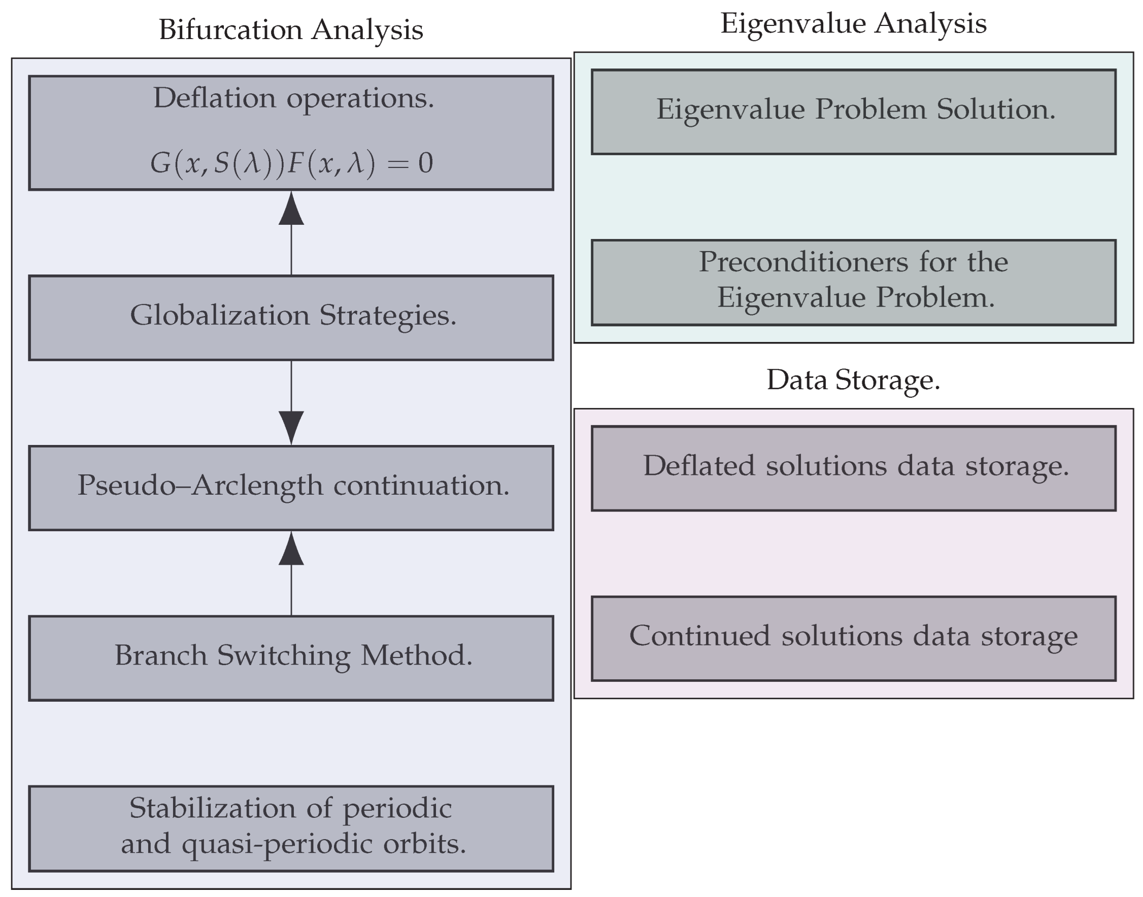
The structure of the current bifurcation analysis and simulation software is outlined in Figure 1 and Figure 2.
The implementation of the software was performed using template metaprogramming in C++ and CUDA C++. Parallelization was implemented using the Message-Passing Interface (MPI) for distributed memory, Open Multi-Processing (OpenMP), and the NVIDIA Compute Unified Device Architecture (CUDA) for central and Graphics Processing Units (GPUs). Each block of a different color depicts a different namespace. The software, developed by the authors, is based on a set of publications: some were published, and some are to be published and are referenced in the namespaces’ descriptions. The namespaces are distributed between a user-provided problem description (discrete models of fluid dynamics problems) [39,48,49], methods that perform automatic bifurcation analysis [30,31], methods that solve nonlinear problems, methods that solve eigenvalue problems [50,51], methods that remove continuous and discrete symmetries, methods that solve large-scale linear problems and perform basic operations on linear spaces [52,53,54,55], and the solutions’ storage database.
Next, we shall consider different parts of the designed software that were not discussed before and show some specific features that we used to perform bifurcation analysis.

2.1. Time Marching Integration

The time-marching algorithm is one of the main parts of the simulation process, and it is also used to perform the Poincare shooting method in the deflation and continuation of periodic orbits. The simulation of solutions that correspond to the invariant s-dimensional tori also requires time marching with millions of time steps. In this subsection, we shall analyze the behavior of the time-stepping algorithms on inertial manifolds and discuss possible increases in precision for the standard time-marching methods.
The first important property of our implementation is the usage of Diagonally Implicit (DIRK) or Semi-Implicit (IMEX) Runge–Kutta (RK) methods, which are L- and B-stable in their implicit part; see [56,57,58]. Let g ( z ) be a stability function of an RK method. The method is stable for such z C , so that | g ( z ) | < 1 . The last inequality generates a region S C for which the method is linearly stable, i.e.,
S ( z ) : = z C : g ( z ) = exp ( i θ ) , θ [ 0 , 2 π ] .
An important property of these methods (and any methods that we applied in our simulations) is that a segment of the imaginary axis (or the whole axis) is enclosed inside S . In this case, the following estimate is known. Assume that the Jacobi matrix of (2) J ( u ) has the following property: for some set U that represents a set of solutions, the symmetric part A ( u ) : = ( J ( u ) + J ( u ) * ) / 2 of the matrix is such that ( A ( u ) ξ , ξ ) 0 , ξ , u U . The system (2) can be written in the following form for any RK method on the n-th step:
u n + 1 = F ^ k ( τ , u n , u n + 1 , F ) , u 0 = u 0
u n + 1 = τ F ^ k ( u n , u n + 1 , F ) + ε , u 0 = u 0 + ε ,
where F ^ k is the RK operator or order k, which is built around the current and previous steps, time step τ , F , and the Butcher tableau; u is a perturbed solution with the small perturbation ε . The error is given as e n = u n u n . If the above-listed property of the Jacobi matrix is true, then:
e n exp ( C 1 ) e 0 + O ( τ k 1 ) exp ( C 2 ) ,
where constants C 1 and C 2 are independent of n and τ . Hence, for a periodic orbit, one usually obtains satisfactory simulation results. Such an estimate cannot hold for other types of attracting sets, such as quasi-periodic orbits or chaotic attractors. However, if one assumes the existence of an Inertial Manifold (IM), then the estimate can be extended. Define an IM [5]. Let B : = H be a Hilbert space of the original system (1) with the distance function dist ( · , · ) ; this system can be rewritten in terms of the semi-group translation form u ( t ) : = φ ( F ) t u ( 0 ) , with the t state a continuous or discrete time and u ( 0 ) an allowed initial condition.
Definition 1.
Let the manifold M enjoy the following properties:
  • dim ( M ) = m < ;
  • t > 0 : φ ( F ) M M ;
  • t > 0 and u ( 0 ) H , there exist constants c 1 > 0 and c 2 > 0 s.t. dist ( φ ( F ) t u ( 0 ) , M ) c 1 exp ( c 2 t ) .
Such a manifold M is called an inertial manifold.
Notice that the existence of the IM for a particular problem (1) needs to be proven and requires some strong conditions on the operator spectrum (spectral gap condition; see [59,60]). Since we are interested in the finite-dimensional representation (2) of the original system (1), we need to assume that the number of Degrees Of Freedom (DOFs) is sufficient to represent the dynamics of the system on the inertial manifold, say using the Galerkin method. Approaches to define these DOFs for different dissipative dynamical systems can be considered in [5,60,61] and, in particular, in [62] for the application in our research related to the problems in fluid dynamics.
Remark 1.
The number (n) of DOFs in the approximation (2) is not directly related to the dimension of the IM (m) given in Definition 1. Sufficient conditions should be provided for the value of n that can represent the dynamics on the IM, for example for space periodic boundary conditions; see [61], Inequality (1.13).
If such conditions are met and withthe system (2), then one can see from the properties in the Definition 1 that the RK methods applied to such systems can simulate dynamics on the approximate inertial manifold if the selected RK methods satisfy the stability conditions. If the condition on the existence of the IM is not met, one can assume the existence of the absorbing manifold that attracts trajectories algebraically quickly.
Nevertheless, for the IM and general absorbing and attracting manifolds, it is desirable to increase the precision of the RK methods and reduce the influence of rounding-off errors because of the usage of floating-point arithmetic. A general pessimistic estimate for the floating-point representation of Runge–Kutta methods is well known; for example, see [63]. Let us designate the floating-point representation of u n on step n as u n ˜ . Then, the floating-point error e ˜ n = u n u n ˜ can be estimated as:
e ˜ n < C γ n / τ ,
where C is a constant (encompassing a maximum from a solution value at different steps that do not depend on the time step values), τ is the time step floating-point representation, and γ n is the quantity of the rounding error estimates, given as:
γ n = n ε 1 n ε ,
when n ε < 1 and ε is the unit round-off (or macheps) of the selected floating-point arithmetic, usually represented as ε = 2 p , where p is the number of significant bits (for example, ε = 2 53 for double-precision in the IEEE 754 standard). One can observe that, for many time steps and a small value of τ n , the round-off floating-point error becomes significant. Notice that a refined estimate is provided in [64].
The improvement of the estimate (5) can be made by either using extended precision floating-point arithmetic or by using the compensated summation algorithm. The first approach can be achieved by using standard libraries for CPUs or custom implementations for GPUs, for example [65]. However, it is known that, for GPUs, such an approach greatly reduces performance. In our research, we used the second approach, which is discussed in detail in [54]. We shall indicate any operation that is executed using floating-point arithmetic as fl ( · ) , which includes all operations inside the brackets. The floating-point-compensated operations that are to be used are based on error-free operations, presented in Algorithms 1 and 2; for more information, see [54].
Algorithm 1 Error-free addition s.t. s + c = a + b , s = fl ( a + b ) , and c ε ( a + b ) .
1:
function add(a, b)
2:
     s = fl ( a + b ) ;
3:
     z = fl ( s a ) ;
4:
     c = fl ( ( a ( s z ) ) + ( b z ) ) ;
5:
    return (s, c);
Algorithm 2 Error-free multiplication s.t.: s + c = a b , s = fl ( a b ) , and c ε | a b |
1:
function MUL(a, b)
2:
     s = fl ( a b ) ;
3:
     c = FMA ( a , b , s ) ;
4:
    return (s, c);
In light of the RK methods, one can implement such an approach as follows. For simplicity, we shall consider the autonomous variant of the method. Let some s-stage RK-method be given in the Butcher’s table in the form of a matrix A and a vector b . As already mentioned, the methods are either SSP-stable (for explicit methods) or B-stable for diagonally implicit methods. For explicit RK methods with the provided general nonlinear function rhs, the system of equations between steps n and n + 1 with summation and product compensations can be written in Algorithm 3. Implicit diagonal RK methods can be constructed in the same fashion, with the additional stage of using Newton’s method to obtain the diagonal values of k . One can formulate the following:
Algorithm 3 Compensated explicit autonomous Runge–Kutta method single-step from n to n + 1 . All variables are presented in the base floating-point precision.
  1:
function erk_internal( τ , ( u , r ) , w, k )
  2:
     ( d , p 1 ) MUL ( τ , w ) ;
  3:
     ( d , p 2 ) MUL ( d , k ) ;
  4:
     ( u , p 3 ) ADD ( u , d ) ;
  5:
     r r + p 1 + p 2 + p 3 ;
  6:
    return ( u , r )
  7:
function erk( ( u , r ) n + 1 , ( u , r ) n , τ n , rhs, A , b )
  8:
     k j = 1 , . . , s 0 ; s LEN ( b ) ;
  9:
    for  j = 1 , , s  do
10:
         u u n + r n ; q 0 ;
11:
        for  l = 1 , , s  do
12:
            ( u , q ) ERK _ INTERNAL ( τ n , ( u , q ) , A j , l , k l ) ;
13:
         k j RHS ( u + q ) ;
14:
     ( u , r ) n + 1 ( u , r ) n ;
15:
    for  j = 1 , , s  do
17:
         ( u , r ) n + 1 ERK _ INTERNAL ( τ n , ( u , r ) n + 1 , b j , k j ) ;
17:
    return  ( u , r ) n + 1 ;
Theorem 1.
Let the ODE system (2) be given with an identity matrix for M and Lipschitz continuous nonlinear function F . Let the provided initial conditions be consistent with respect to the function F . Let the basic floating-point arithmetic (according to the IEEE 754 standard) be used, and the compensated explicit Runge–Kutta method in the Algorithm 3 is applied to the system (2) with such a sequence of time steps { τ n } , such that n : | g ( τ n , A , b , u n , F ) | < 1 , and now, the underflow of floating-point representation occurs; g is an RK method stability function. Then, the following estimate for the round-off error is true:
e ˜ n < C γ n 2 τ ,
where τ is the minimum accepted time step value and C is a constant that does not depend on the time step.
Proof. 
First, let us obtain an estimate (5). A single step of an S-stage explicit RK method with Butcher’s table coefficients A , b is given as:
K j = F ( u n + τ n l = 1 j 1 a j , l K l ) , j = 1 , , S u n + 1 = u n + τ n j = 1 S b j K j ,
Let us consider a single-step in floating-point operations.
fl K j = F ( u n + τ n l = 1 j 1 a j , l K l ) , j = { 1 , , S } fl u n + 1 = u n + τ n j = 1 S b j K j ,
We used the estimates from [54], Appendix A (Proofs of lemmas and propositions), the Lipschitz continuity of F with Lipschitz constant L, and the stability condition for g, under which we assume that τ n L 1 . Then,
K j fl ( K j ) < ( L ε + 4 j ε ) u n , j = { 1 , , S } .
Then, for the first step, we have:
fl ( u 1 ) u 1 < ( 2 ε + 4 τ 1 ( 3 S 2 + S ) / 2 ε ) u 0 .
By using induction and maximizing the time steps ( τ = max k [ 1 n ] τ n ), we arrive at:
fl ( u n + 1 ) u n + 1 < ( 2 n ε + 2 τ n ( 3 S 2 + S ) ε ) max k [ 1 n ] u k .
The latter can be bounded to obtain Inequality (5):
e ˜ n = u ˜ n u n < τ n ( 2 / τ + 6 S 2 + 2 S ) ε C 1 C γ n / τ .
Now, we considered Algorithm 3. The same manipulations can be performed, taking into account the compensated algorithms and using prefix induction; see Lemma 1 from [54]. Then:
K j fl ( K j ) < ( L ε 2 + 6 j ε 2 ) u n , j = { 1 , , S } ,
fl ( u n + 1 ) u n + 1 < ( 2 n ε 2 + 3 τ n ( 9 S 2 + 3 S ) / 2 ε 2 ) max k [ 1 n ] u k .
The latter can be bounded to obtain the results of the theorem as:
e ˜ n = u ˜ n u n < τ n ( 2 / τ + 12 S 2 + 6 S ) ε 2 C 1 C γ n 2 / τ .
Remark 2.
In actual computations, however, the estimate (6) is very pessimistic. Many floating-point errors are compensated and are not essential during long-time calculations.
Let us demonstrate that this approach not only allows one to decrease the time step close to ε , but also to simulate linearly unstable solutions for a substantial simulation time with no loss of accuracy. We considered the Dahlquist equation u t = u subject to the initial conditions u ( 0 ) = 1 with an exact unstable solution u ( t ) = e x p ( t ) . One can observe the error e ˜ n between the exact solution and approximate floating-point solutions in Figure 3.
The results demonstrate that the suggested approach works even better than the application of quadruple-precision floating-points by a factor of 5. Since the base macheps ε = 2 53 1.11 × 10 16 , one can safely decrease the time step to the order of several magnitudes of ε , say about 1.0 × 10 12 , with no worries about losing precision due to the round-off errors. This allows one to select small time steps in the adaptive time step control strategy for general nonlinear F for chaotic attractors near stiff regimes. This approach allowed the authorsto obtain very sensitive attractors of nonlinear systems, such as 3D invariant tori, for example [37].

2.2. Deflation with Discrete Symmetry

In order to reduce the complexity of the problem, it is beneficial to reduce the symmetries of the system if those are known. The symmetries are saved in the system (2) in the case that a correct spatial discretization method is used. One of the most-important reductions is the reduction of continuous symmetries related to the S O ( n ) group. If such a reduction cannot be performed on a discrete level, then it becomes a difficult problem and will be discussed elsewhere. The reduction of discrete symmetries, however, can be performed more easily if the deflated Newton method is used. The discussion here is based on the definitions from [27,30]. First, we consider stationary solutions:
F ( u ) = 0 ,
for a fixed value of the parameter R, which is omitted. Recap the following definition from [27]:
Definition 2.
Let B, C, and D be Banach spaces and U be an open subset of B. Let F : U B C be a Frechet differentiable operator with derivative F . For each r U , u U { r } , let M ( u ; r ) : C D be an invertible linear operator. We say that M is a deflation operator if, for any F s.t. F ( r ) = 0 and F ( r ) nonsingular, we have:
lim j inf M ( u ; r ) F ( u j ) D > 0 ,
for any sequence { u j } converging to r , where u j U { r } .
Let the system (1) be recast into the deflated system by using this definition with the multiple deflation operator G:
G ( u , S ) F ( u ) = 0 ,
where S : = { r j | j = 1 , , K : F ( r j ) = 0 } is the set that contains all K known or previously found solutions. We shall use a particular form of the deflation operator from [30]:
G u , S = 1 K diag j = 1 K u u j 2 p + α j ,
where α k is the shift value, which can be chosen in order to improve the convergence of iterative methods.
Let σ k be a non-trivial element of some discrete finite group σ acting on the solution of the system (7). The nonlinear operator F is invariant under the action of the elements of this group, i.e., if u is a solution of (7), then F ( σ k u ) = σ k F ( u ) = F ( u ) = 0 . However, the deflated system (9) will not be able to take this group element into account (since σ k u u > 0 ), and Newton’s method will converge to the solution. One way to deal with this problem is to wait until all such solutions are found. However, such an approach may require too much memory to store all those solutions. The other approach that we adopted here is to use a modified deflated operator s.t. taking known discrete symmetry elements into account. Such a deflation operator we shall define as a discrete symmetry-invariant deflation operator.
Definition 3.
Let B, C, and D be Banach spaces and U be an open subset of B. Let σ k be an element of a discrete finite group σ. Let F : U B C be invariant under the action of elements from the σ Frechet differentiable operator with derivative F . For each σ k r U , u U k { σ k r } , let M ( u ; r ) : C D be an invertible linear operator. We say that M is a discrete symmetry invariant deflation operator or D-deflation operator if, for any F and σ k σ , such that F ( σ k r ) = 0 and F ( σ k r ) nonsingular, we have:
lim j inf M ( u ; r ) F ( u j ) D > 0 ,
for any sequence { u j } converging to σ k r , where u j U k { σ k r } .
The actual implementation of such a D-deflation operator can be performed in different ways. In the software implementation, we propose the following modification of (10):
G u , S , Q = 1 K + | Q | diag j = 1 K k = 1 | Q | σ k u u j 2 p + α j ,
where the set Q contains the description of all elements of known discrete groups in terms of the action of this group on u . σ k Q . The whole nonlinear operator now becomes:
G ( u , S , Q ) F ( u ) = 0 ,
This form of the proposed operator (13) retains the rather simple form of the original Jacobian operator that was derived in [30].

3. Bifurcation Analysis and Chaotic Dynamics in ABC Flow

In this section, we provide an example of the bifurcation and chaotic analysis of a fluid dynamics problem: a well-known problem of the dynamics in the ABC flow [66] is considered. Although it has been studied intensively, the transition to chaos in this problem is still not fully understood. This example is mainly a demonstration of the approach used by our methodology and software applied to large-scale problems in fluid dynamics. However, some new results were obtained.
The governing equations are given by the incompressible Navier–Stokes equations:
u t + ( u , ) u + p 1 R u 1 R f = 0 , · u = 0 ,
on the periodic domain T 3 : = [ π ; π ] × [ π ; π ] × [ π ; π ] , and the forcing term is given as:
f : = ( A sin ( x 3 ) + C cos ( x 2 ) ; B sin ( x 1 ) + A cos ( x 3 ) ; C sin ( x 2 ) + B cos ( x 1 ) ) T ,
where A , B , C are positive whole numbers and R is the positive real number (Reynolds number) that is used as the bifurcation parameter. Note that f is divergence-free. Equations (14) and (15) formulate the problem (1). The problem has a trivial base solution:
u = f .
A finite-dimensional problem is formulated by expanding the solution using a finite set of trigonometric polynomials and applying Bubnov–Galerkin and divergence-free projections; we arrive at the following ODE system:
u ^ t + P B ( u ^ , u ^ ) R 1 C u ^ R 1 f ^ = 0 ,
where u ^ is the vector of expansion coefficients (DOFs), E is the identity matrix, G is the matrix that represents the gradient operator, G T is the matrix that represents the divergence operator, C is the diagonal matrix that represents the Laplace operator, and P = E G C 1 G T is the Leray–Helmholtz orthogonal projector. The convolution term (nonlinearity) is designated as B , and f ^ is the ABC forcing term (15) projected to the approximating space of polynomials. The system (17) is basically the problem (2) with a unit mass matrix. In order to accelerate the convergence of Newton’s method, we applied the preconditioned gradient descent method before each Newton method iteration.
A detailed analysis of this problem was performed in [67,68,69] by O.Podvigina and co-authors. In this section, we are interested in diving into more details on the initial stage of transition to chaos and constructing bifurcation diagrams to unravel the interaction between stationary, periodic solutions and chaotic regimes. Here, we only considered the case A = B = C = 1 and 1 R 20 . The system (17) is invariant under the action of 24 elements isomorphic to O (octahedral symmetry) and S 4 (permutations of four elements) group elements; see [70] for more details. All elements of these groups were added to the set Q in (12). For the visualization of the bifurcation diagrams, we used the following set of functions, depicted on the figure axes:
L 2 ph : = u L 2 : = ( 8 π 3 ) 1 T 3 | u ( x ) | 2 d x , L 2 : = u ^ l 2 : = N 1 j = 0 N u ^ j u ^ j * , a : = u x 4 π 3 , 2 π 3 , 2 π 3 , b : = u x 4 π 5 , 4 π 3 , 2 π 3 , c : = u x π , 2 π 5 , 2 π 5 , c : = u y π , 2 π 5 , 2 π 5 , d : = u x 2 π , π , π .
We applied the discretization of 128 3 for this problem; hence, the number of DOFs is N = 6 × 128 × 128 × ( 128 / 2 + 1 ) 1 128 / 2 128 / 2 2 ( 128 × 128 ) / 2 6.37 × 10 6 due to the reality condition on the functions. We used two Nvidia GTX TITAN BLACK GPUs to perform the calculations, the base double-precision with error compensation on the blas1 operations, and the compensated ERK fifth-order method (Algorithm 3) for the time-dependent solutions.

3.1. Bifurcation Analysis

First, we performed the deflation and continuation of all stationary solutions. This was performed by first tracing the solution (16), adding solutions at knot points to the deflation operator (for more information; see [30]), and then, using the deflation algorithm on the set of random vectors; each random vector was initialized by divergence-free perturbations. After a new solution was found, it was traced by the pseudo-arc length continuation algorithm. The cycle was repeated until no more solutions were found on the deflation step. For this procedure, we called bifurcation_analysis::deflation_operations and bifurcation_analysis::pseudo_arclength_continuation classes, presented in Figure 2. These methods use the concepts and classes that are provided in Figure 1.
A bifurcation diagram for stationary solutions is presented in Figure 4. Solutions of the problem in physical space are represented at some points by using the iso-surfaces of velocity vector magnitude. Bellow, we shall demonstrate that these stationary solutions are essential for understanding the process of the transition to chaos.
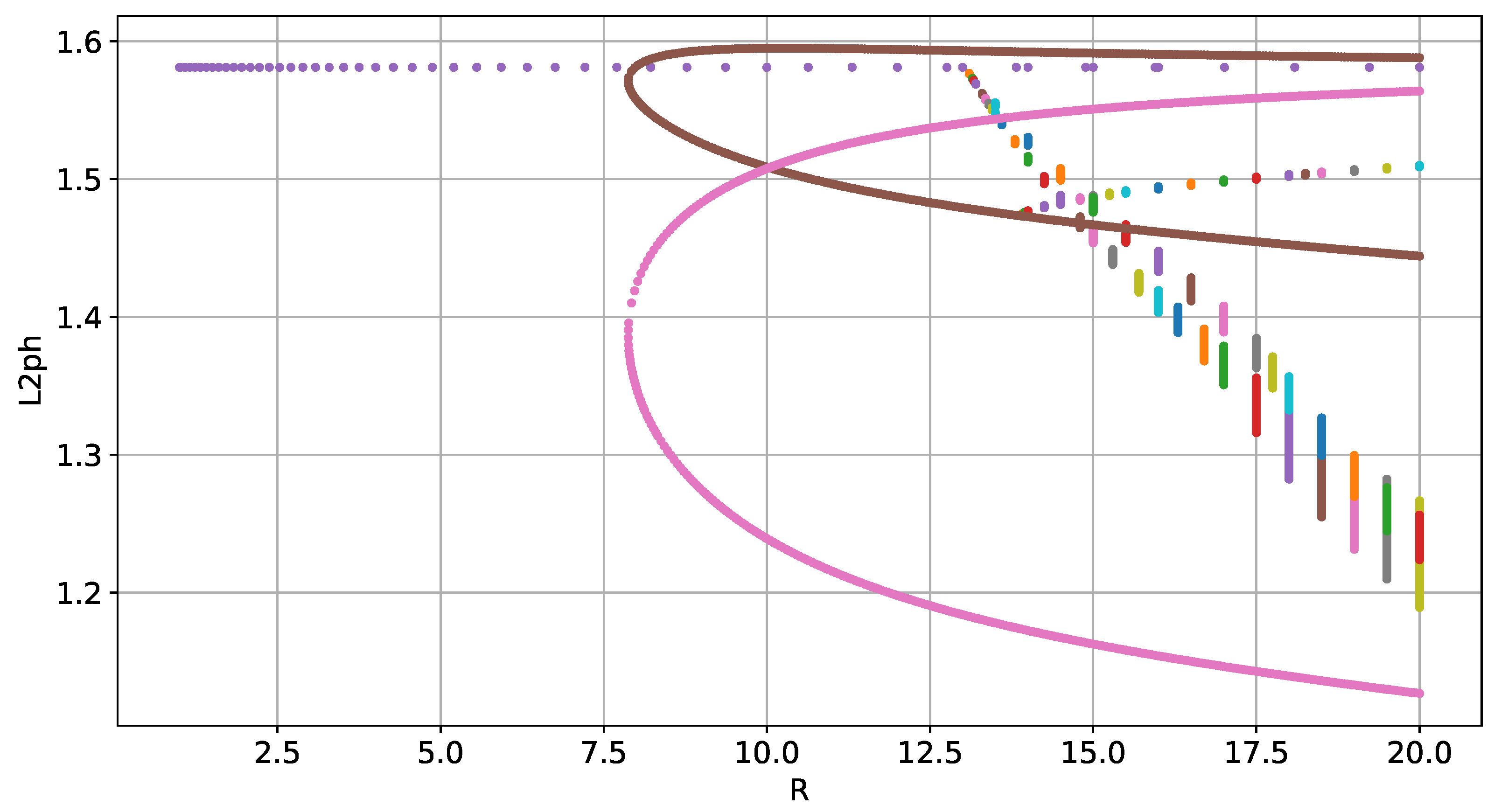
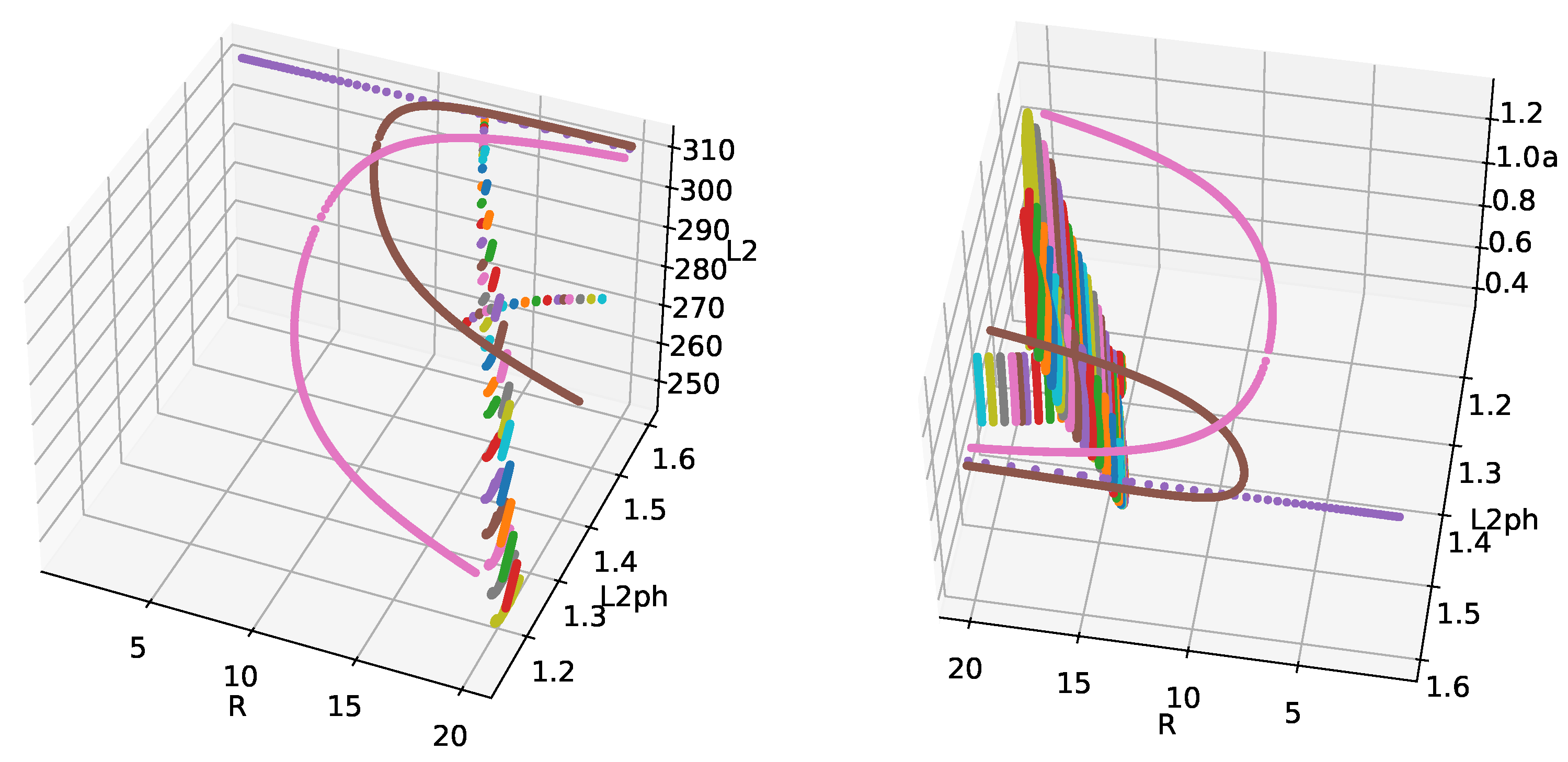
Next, the stability analysis is executed, and bifurcation points are located in the stationary solutions. These bifurcation points are represented in Figure 5 by blue crosses. For the trivial solution branch, all bifurcation points are shown, while only the first loss of stability is shown on secondary branches. The dimension of the unstable manifold is 35 by the last presented bifurcation at R = 15.006 on the main branch, so we can expect the fast growth of instabilities. The existence of multistable stationary solutions can be seen for 7.8753 R 13.0059 between the main trivial branch and two disconnected branches. Additionally, one can see the disconnected nature of these branches in the 3D Figure 6. There are three independent Hopf bifurcations on each branch that form periodic orbits: at R = 13.0059 for the trivial branch and at R = 13.8922 at secondary branches.
The presented branches of periodic orbits were obtained using the reduction of the symmetry of the problem; otherwise, multiple branches would cover the bifurcation diagram entirely for non- L 2 -norms after the first Hopf bifurcation at R = 13.09 and would coincide for L 2 -norms. The periodic orbits that emanated from the secondary branches have a smaller period, with a ratio of about 1 / 3 to the periodic orbits on the main branch.
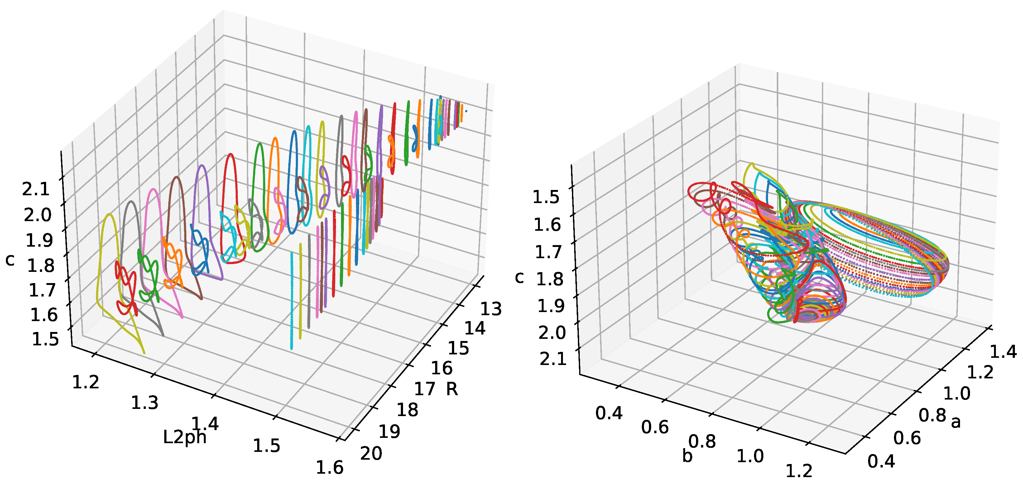
Next, we considered the stabilization of the periodic orbits that bifurcate from the Hopf bifurcation points. The bifurcation diagram is presented in Figure 7 and more projections in different coordinates in Figure 8 and Figure 9.
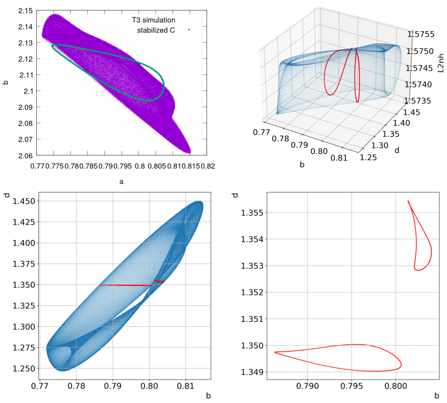
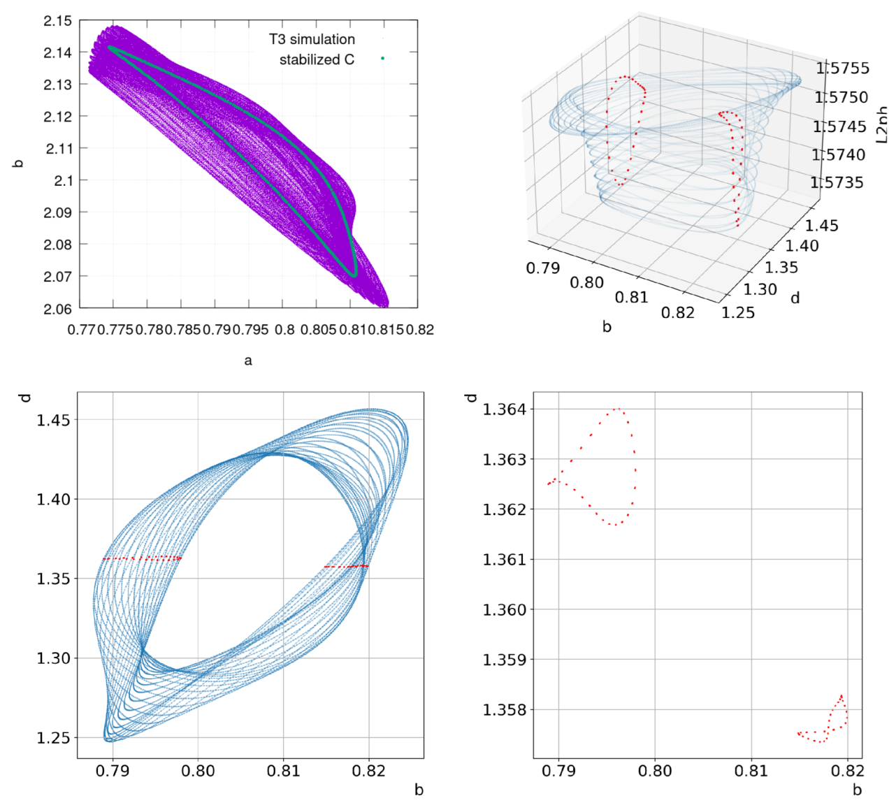
The periodic orbits that emanated from the main branch lose stability almost immediately by the second Hopf bifurcation at R = 13.09 and, then, the third Hopf bifurcation at R = 13.122 ; stable invariant 2D and 3D tori are presented in Figure 10 and Figure 11, respectively, along with stabilized periodic orbits. At R = 13.128 , the 3D torus is transformed into the 2D torus given in Figure 12 by phase locking. This transition is equivalent to the bifurcation scenario outlined in [69].

3.2. Analysis of Chaotic Regimes

Five leading Lyapunov exponents were calculated for the considered chaotic regimes to indirectly indicate chaotic behavior (in general, we believe that such an indication is prone to rounding errors and inaccuracy; see [71] for more details). The procedure of calculating Lyapunov exponents is Jacobian-based with numerically stable reorthogonalization (which is executed as soon as the iteration time is reached or the norm of perturbations increases by 100-times). Each iteration consists of 1 × 10 5 time steps; for more information on calculating Lyapunov exponents for large-scale problems see [72].
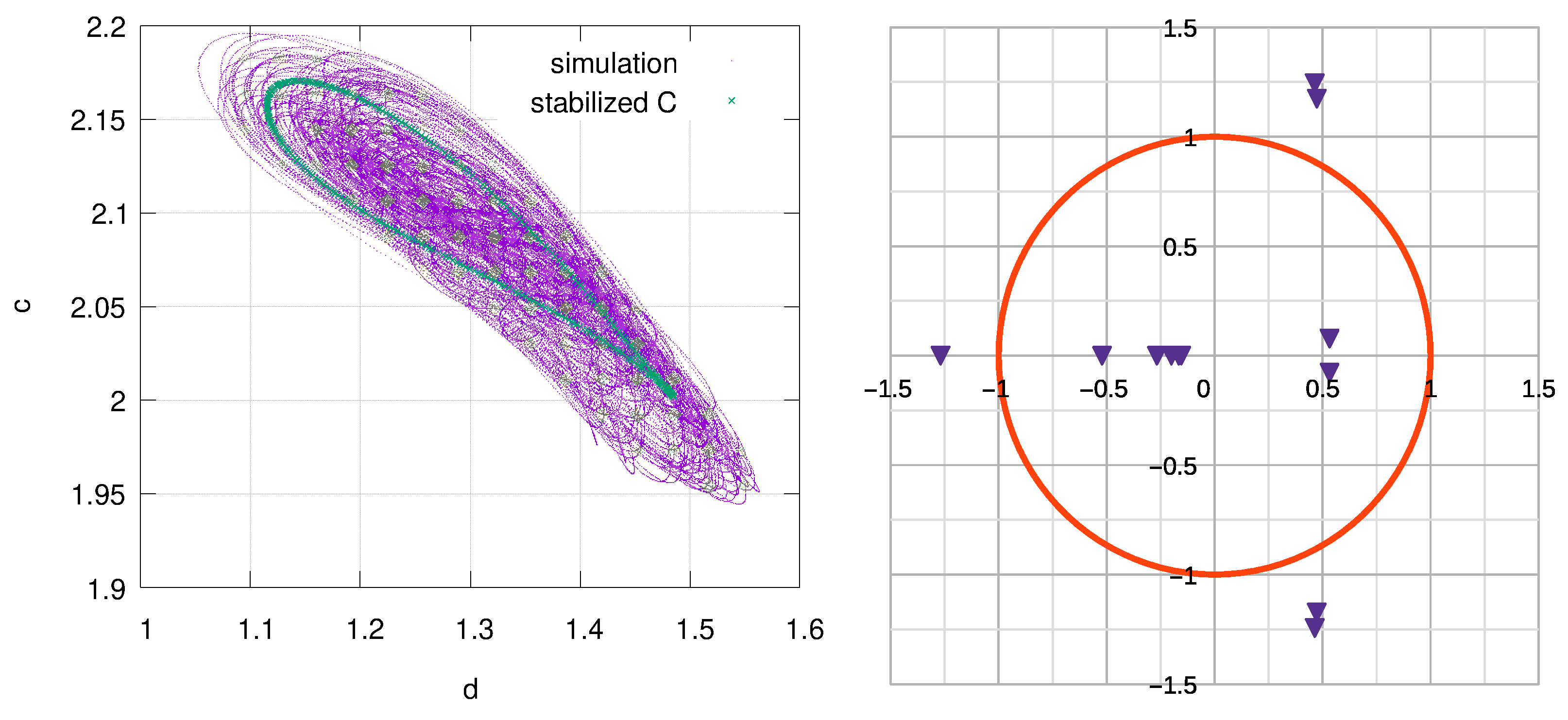
For R > 13.14 , we observe a chaotic behavior; an example of such behavior is shown in Figure 13. The chaotic attractor is located around an unstable periodic orbit, thus producing low-dimensional chaos. The eigenvalues of the monodromy matrix, minus the value at ( 1 , 0 ) , for the given periodic orbit indicate at most a three-dimensional unstable manifold, partially confirmed by the Lyapunov exponents in Figure 14, left. This approach is characterized by low-dimensional chaotic behavior. In this problem, we observed the transition to chaos through 2D and 3D stable invariant tori, followed by phase locking.
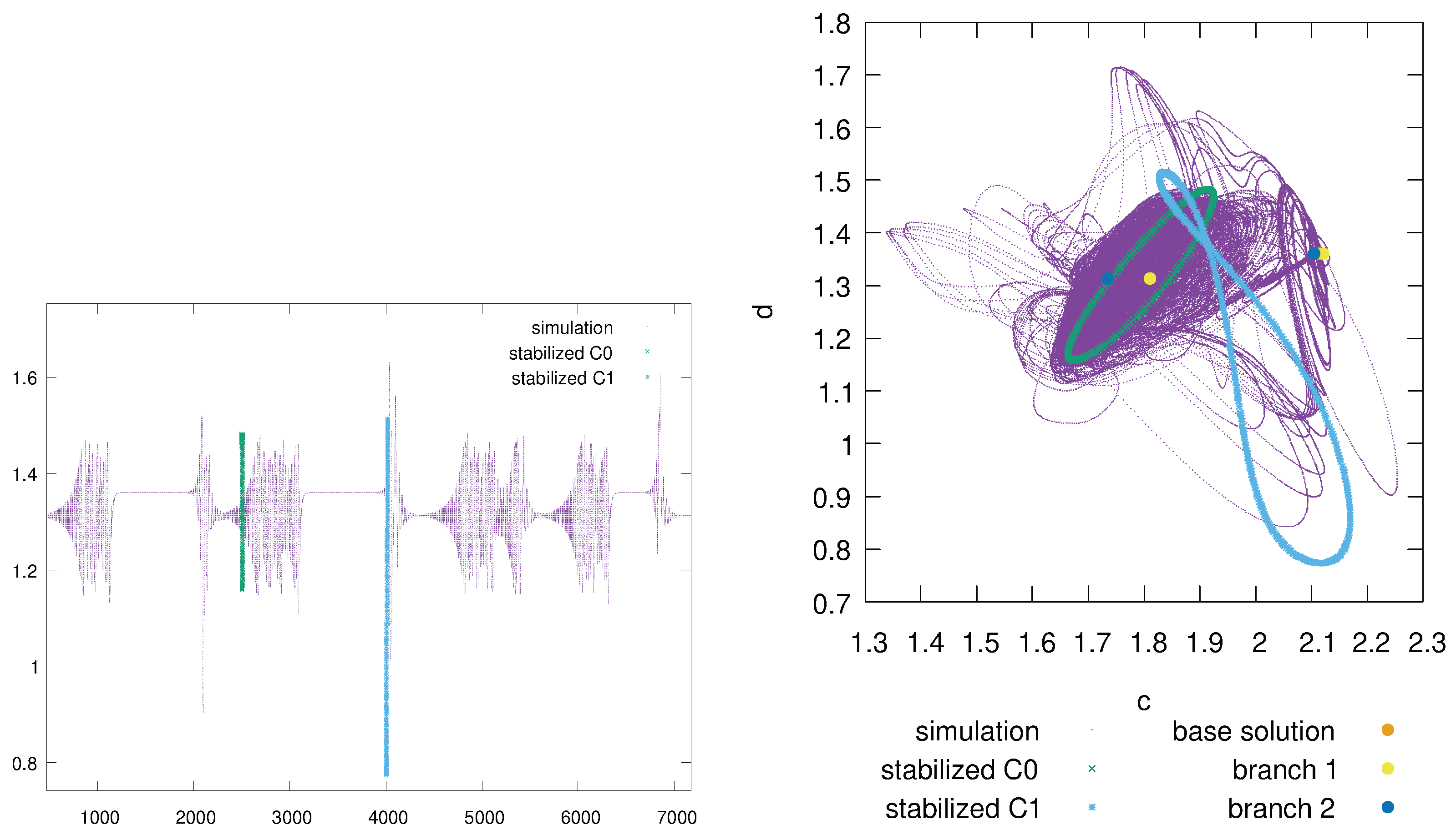
Now, we turn our attention to the chaotic regimes of the considered problem beyond low-dimensional chaos. Starting from R > 13.9 , an intermittent pattern is formulated, which cannot be explained by the stabilized periodic orbits; see Figure 15, where an intermittent pattern with stabilized periodic orbits on this pattern is provided.
The dimension of the unstable manifold with respect to the stabilized periodic orbits is much larger, and 20 leading eigenvalues of the monodromy matrix for both periodic orbits are complex-conjugate pairs located outside the unit circle; see Figure 16. At this stage, we already obtained a set of bifurcations on the unstable stationary solution; see Figure 5. Such a situation usually indicates the increase of the dimension of the unstable manifold. This is partially confirmed by the Lyapunov exponents in Figure 14, right, where all five leading exponents are larger than zero.
The chaotic dynamics is revealed when stationary solutions are considered. A zoomed area is presented in Figure 17.
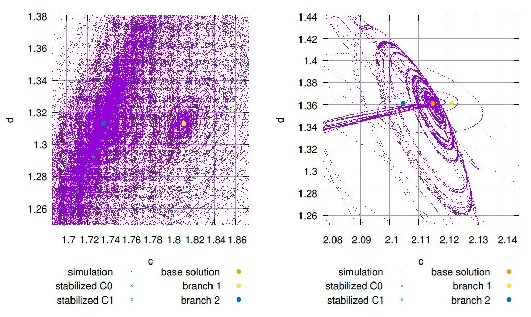
The trajectory is governed by the stable and unstable manifolds around stationary solutions, represented by points in the plots (cut of bifurcation diagram in Figure 4 at R = 15 ). The solutions are controlled by the inherited symmetry of the problem. The stationary unstable solutions are likely to form heteroclinic connections around which the chaotic intermittency is developed. A more-probable clustering of trajectories is presented around new branches of unstable solutions presented in Figure 17 (left), and a less-probable clustering of trajectories is presented around a base flow branch shown in Figure 17 (right). This chaotic intermittent behavior continues at least until the maximum R = 20 , while more symmetries are evolved and R = 20 , almost fully developed chaos is formed; see Figure 18 and Figure 19. An additional unstable stationary branch is obtained by the action of the S 4 symmetry element on the second branch; this symmetric branch solution’s L 2 - and L 2 p h -norms coincide.

4. Discussion

In this paper, we presented a methodology and software for bifurcation and chaotic analysis of abstract dynamic systems given by the formal Equations (1). The software assumes that the user side provides the correct and an efficient implementation of the solution methods for the abstract system, which is listed in Figure 1. The provided approach for the compensated evolution of Runge–Kutta integration for floating-point arithmetic allowed us to trace attractors of higher dimensions (such as a 3D invariant torus). It is interesting to note that the structure of the bifurcation analysis software allows one to add new methods and computational technologies without modifying the underlying algorithms. Still, such an approach may not be optimal, as it is based on the heavy use of C++ template metaprogramming with parallel heterogeneous architectures. Hence, the user experience must be quite high, and it is possible that modern programming languages such as Python and Julia can be more user-friendly for medium-sized problems.
In this research, we presented the analysis of the ABC flow problem, mostly for demonstration purposes; we used only the reviewed software for the analysis. Most of the work, such as the deflation and stability analysis of stationary solutions and the deflation and tracing of periodic solutions, was performed in an automated manner. However, one must point out that the numerical analysis of the quasi-periodic solutions is still a challenging task requiring manual labor. Some papers are known to deal with this problem, for example [73], but additional research is required to determine whether such methods can be used for large-scale problems and can be incorporated into the automated bifurcation analysis software.
The ABC flow that was analyzed in the previous section is of separate interest on its own. The initial stage of the transition to chaos is almost identical to the results from [69]. In addition to the cited paper, we presented detailed bifurcation diagrams of stationary and periodic solutions. This allowed us to reveal more information about the chaotic regime, where chaos is being developed around unstable stationary solutions rather than unstable periodic orbits. This gives us more information on the structure of chaos; it also forces one to study not only unstable periodic orbits of the Navier–Stokes flow (for example, see [74]), but also unstable stationary branches. Our future work will focus on perfecting the software and performing a detailed bifurcation analysis of different fluid dynamics problems that are currently beyond the capabilities of other software.

Author Contributions

Conceptualization: N.A.M. and N.M.E.; methodology: N.M.E.; software: N.M.E.; validation: N.M.E.; formal analysis: N.M.E.; investigation: N.M.E.; resources: N.M.E.; data curation: N.M.E.; writing—original draft preparation: N.M.E.; writing—review and editing: N.A.M. and N.M.E.; visualization: N.M.E.; supervision: N.A.M.; project administration: N.A.M. and N.M.E.; funding acquisition: N.A.M. and N.M.E. All authors have read and agreed to the published version of the manuscript.

Funding

The research was supported by grants from the Russian Science Foundation (RSF), Numbers 23-21-00095 and 23-21-00107.

Data Availability Statement

Data will be provided upon request, and the discussed software is available at https://github.com/evstigneevnm/deflated_continuation under a GPL-2.0 license, accessed on 5 September 2023.

Conflicts of Interest

The authors declare no conflict of interest.

Abbreviations

The following abbreviations are used in this manuscript:
GPUGraphics Processing Unit
CPUCentral Processing Unit
RKRunge–Kutta method
DIRKDiagonally Implicit Runge–Kutta method
SDIRKSingly Diagonally Implicit Runge–Kutta method
IMEXImplicit–Explicit Method
IMInertial Manifold
DOFsDegrees Of Freedom
SSPStrong Stability-Preserving
ODEOrdinary Differential Equation
RK3SSPRK explicit Third-order SSP
ABCArnold–Beltrami–Childress flow
CUDACompute Unified Device Architecture
OpenMPOpen Multi-Processing
MPIMessage-Passing Interface
DNSDirect Numerical Simulation

References

  1. Salahifard, H.; Vaezpour, S.M. Bifurcation problems for noncompact operators. Miskolc Math. Notes 2016, 17, 571. [Google Scholar] [CrossRef]
  2. Elhajji, S.; Errachid, M. Analysis of a bifurcation problem. Math. Comput. Simul. 2002, 58, 231–245. [Google Scholar] [CrossRef]
  3. Guo, S.; Wu, J. Lyapunov–Schmidt Reduction. In Applied Mathematical Sciences; Springer: New York, NY, USA, 2013; pp. 119–151. [Google Scholar] [CrossRef]
  4. Carr, J. Applications of Centre Manifold Theory; Springer US: Greer, SC, USA, 1981. [Google Scholar] [CrossRef]
  5. Temam, R. Infinite-Dimensional Dynamical Systems in Mechanics and Physics; Springer: New York, NY, USA, 1997. [Google Scholar] [CrossRef]
  6. Golubitsky, M.; Stewart, I.; Schaeffer, D.G. Singularities and Groups in Bifurcation Theory; Springer: New York, NY, USA, 1988. [Google Scholar] [CrossRef]
  7. Temple, B.; Young, R. A Liapunov-Schmidt Reduction for Time-Periodic Solutions of the Compressible Euler Equations. Methods Appl. Anal. 2010, 17, 225–262. [Google Scholar] [CrossRef]
  8. Yudovich, V. Non-stationary flow of an ideal incompressible liquid. USSR Comput. Math. Math. Phys. 1963, 3, 1407–1456. [Google Scholar] [CrossRef]
  9. Judovič, V.I. An Example of Loss of Stability and Generation of a Secondary Flow in a Closed Vessel. Math. USSR Sb. 1967, 3, 519–533. [Google Scholar] [CrossRef]
  10. Kurakin, L.G.; Yudovich, V.I. On Equilibrium Bifurcations in the Cosymmetry Collapse of a Dynamical System. Sib. Math. J. 2004, 45, 294–310. [Google Scholar] [CrossRef]
  11. Agrachev, A.A.; Sarychev, A.V. Controllability of 2D Euler and Navier–Stokes Equations by Degenerate Forcing. Commun. Math. Phys. 2006, 265, 673–697. [Google Scholar] [CrossRef]
  12. Sapronov, Y. Modelling Liquid Flows in Diffusers by Reduced Equations. Bull. Susu. MMP 2014, 7, 74–86. [Google Scholar] [CrossRef]
  13. Rehman, K.U.; Malik, M. On Lie symmetry mechanics for Navier–Stokes equations unified with non-Newtonian fluid model: A classical directory. Phys. A Stat. Mech. Its Appl. 2019, 535, 122469. [Google Scholar] [CrossRef]
  14. Edwards, W.; Tuckerman, L.; Friesner, R.; Sorensen, D. Krylov Methods for the Incompressible Navier–Stokes Equations. J. Comput. Phys. 1994, 110, 82–102. [Google Scholar] [CrossRef]
  15. Tuckerman, L.S.; Barkley, D. Bifurcation Analysis for Timesteppers. In The IMA Volumes in Mathematics and Its Applications; Springer: New York, NY, USA, 2000; pp. 453–466. [Google Scholar] [CrossRef]
  16. Barkley, D.; Tuckerman, L.S. Stokes preconditioning for the inverse power method. In Fifteenth International Conference on Numerical Methods in Fluid Dynamics; Springer: Berlin/Heidelberg, Geramny, 1997; pp. 75–76. [Google Scholar] [CrossRef]
  17. Tuckerman, L.S.; Huepe, C.; Brachet, M.E. Numerical methods for bifurcation problems. In Instabilities and Nonequilibrium Structures IX; Springer: Dordrecht, The Netherlands, 2004; pp. 75–83. [Google Scholar] [CrossRef]
  18. Sorensen, D.C. Implicitly Restarted Arnoldi/Lanczos Methods for Large Scale Eigenvalue Calculations. In ICASE/LaRC Interdisciplinary Series in Science and Engineering; Springer: Dordrecht, The Netherlands, 1997; pp. 119–165. [Google Scholar] [CrossRef]
  19. Borońska, K.; Tuckerman, L.S. Extreme multiplicity in cylindrical Rayleigh-Bénard convection. I. Time dependence and oscillations. Phys. Rev. E 2010, 81. [Google Scholar] [CrossRef] [PubMed]
  20. Borońska, K.; Tuckerman, L.S. Extreme multiplicity in cylindrical Rayleigh-Bénard convection. II. Bifurcation diagram and symmetry classification. Phys. Rev. E 2010, 81. [Google Scholar] [CrossRef] [PubMed]
  21. Tuckerman, L.S. Computational Challenges of Nonlinear Systems. In Emerging Frontiers in Nonlinear Science; Springer International Publishing: Berlin/Heidelberg, Germany, 2020; pp. 249–277. [Google Scholar] [CrossRef]
  22. Sanchez, J.; Marques, F.; Lopez, J. A Continuation and Bifurcation Technique for Navier–Stokes Flows. J. Comput. Phys. 2002, 180, 78–98. [Google Scholar] [CrossRef]
  23. Sánchez, J.; Net, M.; Garcia-Archilla, B.; Simo, C. Newton–Krylov continuation of periodic orbits for Navier–Stokes flows. J. Comput. Phys. 2004, 201, 13–33. [Google Scholar] [CrossRef]
  24. Sánchez, J.; Net, M.; Simó, C. Computation of invariant tori by Newton–Krylov methods in large-scale dissipative systems. Phys. D Nonlinear Phenom. 2010, 239, 123–133. [Google Scholar] [CrossRef]
  25. Chen, W.; Wang, Q.; Hesthaven, J.S.; Zhang, C. Physics-informed machine learning for reduced-order modeling of nonlinear problems. J. Comput. Phys. 2021, 446, 110666. [Google Scholar] [CrossRef]
  26. Pichi, F.; Ballarin, F.; Rozza, G.; Hesthaven, J.S. An artificial neural network approach to bifurcating phenomena in computational fluid dynamics. Comput. Fluids 2023, 254, 105813. [Google Scholar] [CrossRef]
  27. Farrell, P.E.; Birkisson, Á.; Funke, S.W. Deflation Techniques for Finding Distinct Solutions of Nonlinear Partial Differential Equations. SIAM J. Sci. Comput. 2015, 37, A2026–A2045. [Google Scholar] [CrossRef]
  28. Kalantonis, V.; Perdios, E.; Perdiou, A.; Ragos, O.; Vrahatis, M. Deflation techniques for the determination of periodic solutions of a certain period. Astrophys. Space Sci. 2003, 288, 591–599. [Google Scholar] [CrossRef]
  29. Davidenko, D. On a new method of numerical solution of systems of nonlinear equations. Dokladi AN USSR (Russian) 1953, 88, 601–602. [Google Scholar]
  30. Evstigneev, N.M. On the Convergence Acceleration and Parallel Implementation of Continuation in Disconnected Bifurcation Diagrams for Large-Scale Problems. In Communications in Computer and Information Science; Springer International Publishing: Berlin/Heidelberg, Germany, 2019; pp. 122–138. [Google Scholar] [CrossRef]
  31. Evstigneev, N.M. Deflation of Periodic Orbits in Large-Scale Systems: Algorithm and Parallel Implementation. In Communications in Computer and Information Science; Springer International Publishing: Berlin/Heidelberg, Germany, 2021; pp. 76–91. [Google Scholar] [CrossRef]
  32. Boullé, N.; Dallas, V.; Farrell, P.E. Bifurcation analysis of two-dimensional Rayleigh-Bénard convection using deflation. Phys. Rev. E 2022, 105. [Google Scholar] [CrossRef] [PubMed]
  33. Evstigneev, N.M. Disconnected stationary solutions for 2D Kolmogorov flow problem in periodic domain. J. Phys. Conf. Ser. 2021, 1730, 012078. [Google Scholar] [CrossRef]
  34. Evstigneev, N.M. Disconnected stationary solutions for 3D Kolmogorov flow problem: Preliminary results. J. Phys. Conf. Ser. 2021, 2090, 012046. [Google Scholar] [CrossRef]
  35. Evstigneev, N.M.; Magnitskii, N.A.; Silaev, D.A. Qualitative analysis of dynamics in Kolmogorov’s problem on a flow of a viscous incompressible fluid. Diff. Equat. 2015, 51, 1292–1305. [Google Scholar] [CrossRef]
  36. Evstigneev, N.M.; Magnitskii, N.A. Nonlinear Dynamics of Laminar-Turbulent Transition in Generalized 3D Kolmogorov Problem for Incompressible Viscous Fluid at Symmetric Solution Subset. J. Appl. Nonlinear Dyn. 2017, 6, 345–353. [Google Scholar] [CrossRef]
  37. Evstigneev, N.; Magnitskii, N.; Ryabkov, O. Numerical Bifurcation Analysis in 3D Kolmogorov Flow Problem. J. Appl. Nonlinear Dyn. 2019, 8, 595–619. [Google Scholar] [CrossRef]
  38. Evstigneev, N.; Magnitskii, N.; Sidorov, S. Nonlinear dynamics of laminar–turbulent transition in three dimensional Rayleigh–Benard convection. Commun. Nonlinear Sci. Numer. Simul. 2010, 15, 2851–2859. [Google Scholar] [CrossRef]
  39. Evstigneev, N.M.; Magnitskii, N.A. Numerical Analysis of Laminar-Turbulent Bifurcation Scenarios in Kelvin–Helmholtz and Rayleigh–Taylor Instabilities for Compressible Flow. In Turbulence Modelling Approaches—Current State, Development Prospects, Applications; InTech: Rijeka, Croatia, 2017; pp. 29–59. [Google Scholar] [CrossRef]
  40. DoedelJanuary, E.J. Auto94p: An Experimental Parallel Version of Auto; California Institute of Technology: Pasadena, CA, USA, 1995. [Google Scholar]
  41. Dhooge, A.; Govaerts, W.; Kuznetsov, Y.A. MATCONT. ACM Trans. Math. Softw. 2003, 29, 141–164. [Google Scholar] [CrossRef]
  42. Back, A.; Guckenheimer, J.M.; Myers, M.; Wicklin, F.J.; Worfolk, P.A. Dstool: Computer assisted exploration of dynamical systems. Notices Am. Math. Soc. 1992, 39, 303–309. [Google Scholar]
  43. Guillot, L.; Cochelin, B.; Vergez, C. A generic and efficient Taylor series–based continuation method using a quadratic recast of smooth nonlinear systems. Int. J. Numer. Methods Eng. 2019, 119, 261–280. [Google Scholar] [CrossRef]
  44. Guillot, L.; Lazarus, A.; Thomas, O.; Vergez, C.; Cochelin, B. A purely frequency based Floquet-Hill formulation for the efficient stability computation of periodic solutions of ordinary differential systems. J. Comput. Phys. 2020, 416, 109477. [Google Scholar] [CrossRef]
  45. Soares, F.; Vergez, C.; Antunes, J.; Cochelin, B.; Debut, V.; Silva, F. Bifurcation analysis of cantilever beams in channel flow. J. Sound Vib. 2023, 567, 117951. [Google Scholar] [CrossRef]
  46. Lust, K.; Roose, D. An Adaptive Newton–Picard Algorithm with Subspace Iteration for Computing Periodic Solutions. SIAM J. Sci. Comput. 1998, 19, 1188–1209. [Google Scholar] [CrossRef]
  47. Veltz, R. BifurcationKit.jl. 2020. Available online: https://hal.archives-ouvertes.fr/hal-02346 (accessed on 5 September 2023).
  48. Evstigneev, N.M.; Ryabkov, O.I. On the mixed approximation type pressure correction method for incompressible Navier–Stokes equations. J. Phys. Conf. Ser. 2018, 1141, 012119. [Google Scholar] [CrossRef]
  49. Evstigneev, N.M.; Ryabkov, O.I. Pressure—Velocity projection method with mixed type approximation for Oseen discrete operator. J. Phys. Conf. Ser. 2019, 1391, 012072. [Google Scholar] [CrossRef]
  50. Evstigneev, N.M. Implementation of Implicitly Restarted Arnoldi Method on MultiGPU Architecture with Application to Fluid Dynamics Problems. In Communications in Computer and Information Science; Springer International Publishing: Berlin/Heidelberg, Germany, 2017; pp. 301–316. [Google Scholar] [CrossRef]
  51. Evstigneev, N.M. Inexact matrix exponential preconditioner for implicitly restarted Arnoldi method in fluid dynamics stability problems for parallel heterogeneous architecture. J. Phys. Conf. Ser. 2018, 1141, 012121. [Google Scholar] [CrossRef]
  52. Evstigneev, N.M. Numerical analysis of Krylov multigrid methods for stationary advection-diffusion equation. J. Phys. Conf. Ser. 2019, 1391, 012080. [Google Scholar] [CrossRef]
  53. Bocharov, A.; Evstigneev, N.; Petrovskiy, V.; Ryabkov, O.; Teplyakov, I. Implicit method for the solution of supersonic and hypersonic 3D flow problems with Lower-Upper Symmetric-Gauss-Seidel preconditioner on multiple graphics processing units. J. Comput. Phys. 2020, 406, 109189. [Google Scholar] [CrossRef]
  54. Evstigneev, N.; Ryabkov, O.; Bocharov, A.; Petrovskiy, V.; Teplyakov, I. Compensated summation and dot product algorithms for floating-point vectors on parallel architectures: Error bounds, implementation and application in the Krylov subspace methods. J. Comput. Appl. Math. 2022, 414, 114434. [Google Scholar] [CrossRef]
  55. Evstigneev, N.M. Analysis of Block Stokes-Algebraic Multigrid Preconditioners on GPU Implementations. In Communications in Computer and Information Science; Springer International Publishing: Berlin/Heidelberg, Germany, 2022; pp. 116–130. [Google Scholar] [CrossRef]
  56. Ascher, U.M.; Ruuth, S.J.; Spiteri, R.J. Implicit-explicit Runge–Kutta methods for time-dependent partial differential equations. Appl. Numer. Math. 1997, 25, 151–167. [Google Scholar] [CrossRef]
  57. Koto, T. IMEX Runge–Kutta schemes for reaction–diffusion equations. J. Comput. Appl. Math. 2008, 215, 182–195. [Google Scholar] [CrossRef]
  58. Chertock, A.; Cui, S.; Kurganov, A.; Wu, T. Steady State and Sign Preserving Semi-Implicit Runge–Kutta Methods for ODEs with Stiff Damping Term. SIAM J. Numer. Anal. 2015, 53, 2008–2029. [Google Scholar] [CrossRef]
  59. Temam, R. Inertial manifolds. Math. Intell. 1990, 12, 68–74. [Google Scholar] [CrossRef]
  60. Temam, R. Inertial manifolds and slow manifolds. In The Mathematics of Models for Climatology and Environment; Springer: Berlin/Heidelberg, Geramny, 1997; pp. 181–214. [Google Scholar] [CrossRef]
  61. Temam, R. Approximation of attractors, large eddy simulations and multiscale methods. Proc. R. Soc. Lond. A 1991, 434, 23–39. [Google Scholar] [CrossRef]
  62. Evstigneev, N.; Magnitskii, N. FSM Scenarios of Laminar-Turbulent Transition in Incompressible Fluids. In Nonlinearity, Bifurcation and Chaos—Theory and Applications; InTech: Rijeka, Croatia, 2012. [Google Scholar] [CrossRef]
  63. Butcher, J.C. Numerical Methods for Ordinary Differential Equations; Wiley: Hoboken, NJ, USA, 2016. [Google Scholar] [CrossRef]
  64. Boldo, S.; Faissole, F.; Chapoutot, A. Round-Off Error and Exceptional Behavior Analysis of Explicit Runge–Kutta Methods. IEEE Trans. Comput. 2020, 69, 1745–1756. [Google Scholar] [CrossRef]
  65. Nakayama, T.; Takahashi, D. Implementation of Multiple-Precision Floating-Point Arithmetic Library for GPU Computing. In Proceedings of the Parallel and Distributed Computing and Systems, ACTAPRESS, Dallas, TX, USA, 14–16 December 2011. [Google Scholar] [CrossRef]
  66. Arnold, V.I. Sur la topologie des écoulements stationnaires des fluides parfaits. In Vladimir I. Arnold—Collected Works; Springer: Berlin/Heidelberg, Germany, 1965; pp. 15–18. [Google Scholar] [CrossRef]
  67. Podvigina, O.M. Spatially-periodic steady solutions to the three-dimensional Navier–Stokes equation with the ABC-force. Phys. D Nonlinear Phenom. 1999, 128, 250–272. [Google Scholar] [CrossRef]
  68. Ashwin, P.; Podvigina, O. Hopf bifurcation with cubic symmetry and instability of ABC flow. Proc. R. Soc. London. Ser. A Math. Phys. Eng. Sci. 2003, 459, 1801–1827. [Google Scholar] [CrossRef]
  69. Podvigina, O.; Ashwin, P.; Hawker, D. Modelling instability of ABC flow using a mode interaction between steady and Hopf bifurcations with rotational symmetries of the cube. Phys. D Nonlinear Phenom. 2006, 215, 62–79. [Google Scholar] [CrossRef]
  70. Podvigina, O.M. Investigation of the ABC flow instability with application of centre manifold reduction. Dyn. Syst. 2006, 21, 191–208. [Google Scholar] [CrossRef]
  71. Magnitskii, N.A. Universal Bifurcation Chaos Theory and Its New Applications. Mathematics 2023, 11, 2536. [Google Scholar] [CrossRef]
  72. Skokos, C.; Gottwald, G.A.; Laskar, J. (Eds.) Chaos Detection and Predictability; Springer: Berlin/Heidelberg, Germany, 2016. [Google Scholar] [CrossRef]
  73. Parker, J.P.; Schneider, T.M. Invariant tori in dissipative hyperchaos. Chaos 2022, 32, 113102. [Google Scholar] [CrossRef] [PubMed]
  74. Lucas, D.; Kerswell, R. Spatiotemporal dynamics in two-dimensional Kolmogorov flow over large domains. J. Fluid Mech. 2014, 750, 518–554. [Google Scholar] [CrossRef]
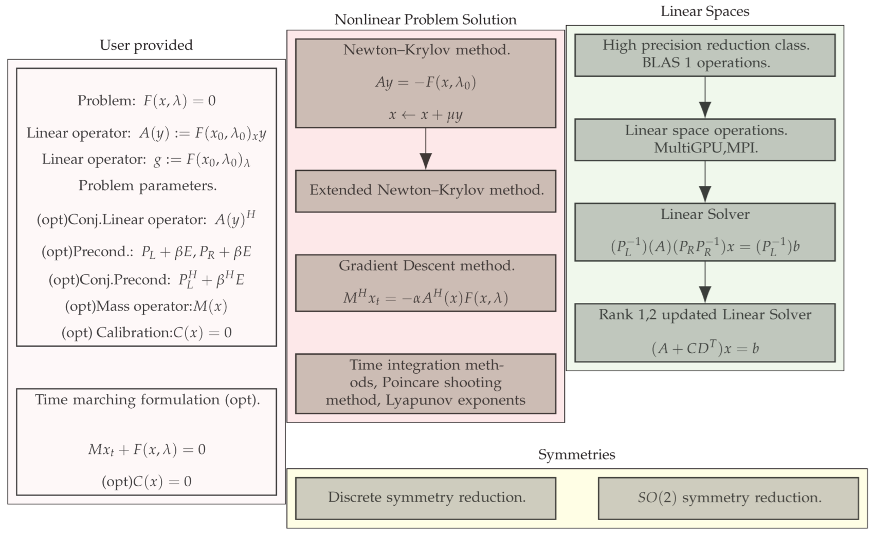
Figure 1. Structure of the high-performance bifurcation analysis software: Part 1. The designation “(opt)” means optional classes or parameters provided by a user.
Mathematics 11 03875 g001
Figure 2. Structure of the high-performance bifurcation analysis software: Part 2.
Mathematics 11 03875 g002
Figure 3. Error for the floating-point solutions with respect to the exact solutions of the Dahlquist equation with τ = 1.0 × 10 12 against the number of time steps (up to 1 × 10 7 ) using the RK3SSP method with different approaches: fp64—64 bit double-precision floating-points, fp64 comp—64 bit double-precision floating-points and Algorithm 3, fp128—128 bit quad-precision floating-points.
Mathematics 11 03875 g003
Figure 4. ABC flow bifurcation diagram of 3 stationary branches (each color represents different stationary branch). Solutions are depicted with absolute iso-surfaces of velocities at some points for better representation.
Mathematics 11 03875 g004
Figure 5. ABC flow bifurcation stability diagram of stationary solutions: black points are stable solutions; red points are unstable solutions; blue crosses are bifurcation points. Only the first stability loss is shown on the secondary branches, while the main branch includes all bifurcation points.
Mathematics 11 03875 g005
Figure 6. The 3D bifurcation diagram of stationary solutions in different projections, different color represents different branch; see (18) for the axes’ titles.
Mathematics 11 03875 g006
Figure 7. ABC flow bifurcation diagram of stationary and periodic solutions. Periodic orbits are represented by color segments, bifurcating from the main stationary solution at R = 13.09 and from the secondary secondary solutions at R = 13.122 .
Mathematics 11 03875 g007
Figure 8. The 3D bifurcation diagram of stationary and periodic solutions in different projections; see (18) for the axes’ titles.
Mathematics 11 03875 g008
Figure 9. The 3D diagrams for stabilized periodic orbits in different projections; see (18) for the axes’ titles.
Mathematics 11 03875 g009
Figure 10. The 2D invariant stable torus for R = 13.123 , left to right, top to bottom: projection and stabilized periodic orbit, phase space projection to 3D subspace with plane section, phase space projection to 2D subspace with plane section, 2D plane section. See (18) for the axes’ titles.
Mathematics 11 03875 g010
Figure 11. The 3D invariant stable torus for R = 13.125 , left to right, top to bottom: projection and stabilized periodic orbit, phase space projection to 3D subspace with plane section, phase space projection to 2D subspace with plane section, secondary 2D plane section at different point. See (18) for the axes’ titles.
Mathematics 11 03875 g011
Figure 12. The 2D phase locking torus for R = 13.13 , left to right, top to bottom: projection and stabilized periodic orbit, phase space projection to 3D subspace with plane section, phase space projection to 2D subspace with plane section, 2D plane section. See (18) for the axes’ titles.
Mathematics 11 03875 g012
Figure 13. Chaotic solution at R = 13.142 and stabilized periodic orbit (left) and leading eigenvalues on the complex plane (with a unit circle for reference) of the monodromy matrix for the stabilized periodic orbit (right).
Mathematics 11 03875 g013
Figure 14. Convergence evolution of five leading Lyapunov exponents ( λ 1 , , λ 5 ) calculated for R = 13.142 (left) and R = 15.0 (right). Each iteration consists of 1 × 10 5 time steps with stable reorthogonalization.
Mathematics 11 03875 g014
Figure 15. Time evolution at R = 15 and stabilized periodic orbit (left) and projection to the 2D phase subspace with stabilized periodic orbits and stationary solution branches (right).
Mathematics 11 03875 g015
Figure 16. The 20 leading eigenvalues on the complex plane (with the unit circle provided for reference) of the monodromy matrix at R = 15.0 for the first (left) and second (right) stabilized periodic orbits.
Mathematics 11 03875 g016
Figure 17. Zoom of evolution at R = 15 around stationary solutions for more-probable trajectory location (left) and less-probable trajectory location (right).
Mathematics 11 03875 g017
Figure 18. Time evolution at R = 20 and stabilized periodic orbit (left) and projection to the 2D phase subspace with stabilized periodic orbits and stationary solution branches (right).
Mathematics 11 03875 g018
Figure 19. Zoom of evolution at R = 20 around stationary solutions for more-probable trajectory location (left) and less-probable trajectory location (right).
Mathematics 11 03875 g019
Disclaimer/Publisher’s Note: The statements, opinions and data contained in all publications are solely those of the individual author(s) and contributor(s) and not of MDPI and/or the editor(s). MDPI and/or the editor(s) disclaim responsibility for any injury to people or property resulting from any ideas, methods, instructions or products referred to in the content.