Article

Analysis and Compensation of Sun Direction Error on Solar Disk Velocity Difference

1
School of Automation, Central South University, Changsha 410083, China
2
Hunan Provincial Key Laboratory of Optic-Electronic Intelligent Measurement and Control, Changsha 410083, China
3
School of Internet of Things Engineering, Jiangnan University, Wuxi 214082, China
*
Author to whom correspondence should be addressed.
Mathematics 2023, 11(17), 3716; https://doi.org/10.3390/math11173716
Submission received: 3 August 2023 / Revised: 25 August 2023 / Accepted: 28 August 2023 / Published: 29 August 2023

Abstract

:
Solar disk velocity difference is an emerging celestial navigation measurement acquired through four spectrometers positioned on the four corners of the quadrangular pyramid. The alignment of the pyramid’s axis with the direction from the sun to the spacecraft is crucial. However, the sun sensor measurement error inevitably leads to the sun direction error, which both significantly affect navigation accuracy. To address this issue, this article proposes an augmented state sun direction/solar disk velocity difference integrated navigation method. By analyzing the impact of the sun direction error on sun direction and solar disk velocity difference measurements, the errors of the solar elevation and azimuth angle are extended to the state vector. The navigation method establishes state and measurement models that consider these errors. Simulation results show that the position error and velocity error of the proposed method are reduced by 97.51% and 96.91% compared with those of the integrated navigation with the sun direction error, respectively. The result demonstrates that the proposed method effectively mitigates the impact of sun direction error on navigation performance. In addition, the proposed method can maintain a satisfactory error suppression effect under different sun direction error values.

1. Introduction

Deep space exploration serves as a significant way for mankind to explore the enigmas of the universe and seek sustainable development, and it is a major emerging field that can expand human living space and enrich human cognition [1,2]. On 17 August 1958, Pioneer 0, the American lunar probe, was successfully launched, which marked mankind officially entering the field of deep space exploration. By June 2022, humans had conducted about 260 deep space exploration missions. The detected celestial bodies include the moon, the sun, large planets and their satellites, dwarf planets, and bodies beyond the solar system [3,4]. Out of all the stars, the sun is the nearest one to mankind. Solar activities will cause serious damage to the Earth’s electromagnetic environment, especially sunspot, solar flare, and coronal mass ejection [5,6,7]. Therefore, the detection and study of solar activity have the potential to mitigate or prevent negative impacts of solar activity on the Earth [8]. Deep space exploration and the study of the sun are closely connected, as they both involve understanding the vastness and complexity of our universe. The Parker Solar Probe was launched by NASA in August 2018, which is designed to study the outer atmosphere of the sun, known as the corona. It will provide valuable data about solar wind, magnetic fields, and other phenomena. The Solar Orbiter was launched in February 2020, which aims to study the sun’s polar regions and gather information about the solar wind, solar flares, and other phenomena that affect space weather. At present, there have been over 70 satellites launched worldwide for the purpose of solar observation [9,10,11,12].
Although mainstream ground-based radio navigation meets the accuracy requirement of deep space exploration tasks, it has some inevitable weaknesses, such as long communication delays, vulnerability to interference, and high costs [13]. These weaknesses are not favorable to the successful execution of long-distance detection tasks. Thus, autonomous navigation has attracted wide attention at home and abroad due to its real-time performance and low operation cost [14,15]. Celestial navigation is an effective autonomous navigation method for spacecraft to explore deep space [16]. According to different measurement information, the existing celestial navigation methods fall into three categories: celestial navigation based on star angle [17,18,19], celestial navigation based on X-ray pulsar [20,21], and celestial navigation based on Doppler velocity [22,23]. However, each celestial navigation method has its own characteristics and shortcomings. Therefore, the study of new celestial navigation methods is helpful for mankind to better explore the universe.
Galileo first discovered that the sun rotates when he observed the sunspot. With the improvement in science and technology, the study of the sun is becoming deeper and deeper. Researchers found that points at different latitudes on the solar surface have different radial velocities [24]. The navigation information of the spacecraft can be estimated from the radial velocity information due to its mathematical relationship with the spacecraft’s position. Considering that velocity difference can eliminate the spectrometer error and the periodic fluctuations in solar velocity, Ning [25] proposed a new celestial navigation method based on the solar disk velocity difference. To obtain higher navigation accuracy, Ning [26] proposed the sun direction/solar disk velocity difference integrated navigation method. However, when the spacecraft is far from the sun, the solar center pointed by the sun sensor with error is greatly different from the actual solar center. The error of the sun sensor is categorized into two types: system error and random error, where the magnitude of system error is much larger than random error [27]. Sun direction error caused by the system error of the sun sensor presents a significant challenge to the practical implementation of sun direction/solar disk velocity difference integrated navigation in engineering applications.
This article introduces a novel augmented state sun direction/solar disk velocity difference integrated navigation method. The sun direction and solar disk velocity difference measurements are utilized to obtain the spacecraft’s direction and distance information with respect to the sun, respectively. By analyzing the impact of the sun direction error on integrated navigation, the errors of solar elevation and azimuth angle are incorporated into the state vector. Consequently, the state and measurement models considering these errors are established.
The remaining sections of this article are organized as follows. Section 2 introduces solar disk velocity difference. In Section 3, the impact of the sun direction error on the measurements of sun direction and solar disk velocity difference is analyzed. The state and measurement models of the proposed method are proposed in Section 4. Section 5 provides the simulation conditions and demonstrates the ability of the proposed method to mitigate the sun direction error. In addition, the effects of the sample time, the number of spectrometers, and the sun direction error value on the navigation performance are also analyzed. Conclusions are shown in Section 6.

2. Solar Disk Velocity Difference

Points at different latitudes on the solar surface have different radial velocities, because different latitudes cause different rotation rates on the solar surface [28]. The spectrometer array is shown in Figure 1. The spectrometers S p A , S p B , S p C , and S p D , located on the corners of the pyramid are used to simultaneously measure the corresponding radial velocity at different latitude points. The sun sensor s is installed at the center of the bottom surface of the pyramid. R is the distance from the spectrometer to the sun sensor. h is the vertical distance from the base to the apex of the pyramid. K is the midpoint of S p A S p D . In the spacecraft-centered sensor frame, denoted as s - x s y s z s , s represents the spacecraft, the z s axis is the direction from the base to the apex of the pyramid, the x s axis is perpendicular to S p A S p D , and the y s axis is perpendicular to S p A S p B . The installation angle δ between the spectrometer and the sun sensor can be represented by Equation (1).
δ = tan 1 ( R / h )
Through the spectrometer array, the direction information of the spectrometer array pointing to four points A , B , C , and D on the solar surface are measured. Then, the position vectors of the four points A , B , C , and D in the sun-centered inertial frame are calculated by corresponding equations. The detailed calculation process is shown in [25].
Taking point A as an example, the position vector of point A in the sun-centered inertial frame is r A i = [ x A i y A i z A i ] T . The longitude β A and latitude φ A of point A are calculated through Equation (2).
{ β A = tan 1 ( y A i x A i ) φ A = sin 1 ( z A i R s )
where R s is the solar radius. Similarly, longitude and latitude β B , φ B , β C , φ C , β D , and φ D of points B , C , and D are calculated by Equation (2).
The differential rotation rate v A of the point A is given by:
v A = ( a + b sin 2 ( φ A ) + c sin 4 ( φ A ) ) R s cos φ A
where a = 14.713 ° / d a y ( ± 0.049 ) , b = 2.396 ° / d a y ( ± 0.188 ) , and c = 1.787 ° / d a y ( ± 0.253 ) [25].
Assuming the spacecraft’s position vector with respect to the sun is r p s = [ r p s x r p s y r p s z ] T , the projection v A p s of point A velocity in the sun direction is expressed as:
v A p s = v A r p s / r p s = v A s i n β A r p s x r p s + v A cos β A r p s y r p s = ( a + b sin 2 ( φ A ) + c sin 4 ( φ A ) ) R s cos φ A ( s i n β A r p s x r p s + cos β A r p s y r p s ) + c s
where v A = [ v A sin β A v A cos β A 0 ] is the velocity of point A . c s is the speed of light.
Likewise, the radial velocities v A p s , v B p s , v C p s , and v D p s at points A , B , C , and D are calculated by Equation (4). Considering the periodic change in the solar velocity and the instrument error, the radial velocity difference is introduced.

3. The Impact of Sun Direction Error on Integrated Navigation Measurements

The complementary metal-oxide-semiconductor active pixel sensor is the mainstream high-precision digital sun sensor and its precision can reach 0.01 ° [29,30]. The error of the sun sensor includes system and random errors. System error refers to the deviation of the angle obtained by the sun sensor. System error is mainly caused by the optical refraction of sunlight through the protective glass layer of the sensor [31,32]. The random error includes random noise in measurements [27]. The magnitude of system error is much larger than random error. Therefore, this article mainly studies the influence of sun direction error caused by the system error of the sun sensor on the sun direction and solar disk velocity difference measurements.

3.1. Sun Direction Error

The solar elevation and azimuth angles, denoted as η and ϕ , are obtained using Equation (5).
{ η = s i n 1 ( r p s z r p s ) ϕ = t a n 1 ( r p s y r p s x )
Sun direction error can be reflected by the errors of η and ϕ . Assuming that δ η and δ ϕ are the errors of η and ϕ , which can be expressed as:
{ δ η = η ˜ η δ ϕ = ϕ ˜ ϕ
where η ˜ and ϕ ˜ represent the solar elevation and azimuth angle with errors.

3.2. The Impact of Sun Direction Error on the Solar Disk Velocity Difference

Figure 2 shows the solar disks obtained with and without the sun direction error. The black thick dashed line represents the solar disk obtained without considering the sun direction error. The blue thin dashed line represents the solar disk obtained with considering the sun direction error. Point o and point o are respectively the center of the sun pointed by the sun sensor when the sun direction error is not considered and when the sun direction error is considered. Taking spectrometer S p A as an example, point A and point A ˜ on the solar surface represent the points pointing to the solar disk from spectrometer S p A without and with considering the sun direction error, respectively. Point A and point A ˜ on the solar disk represent the points pointing to the solar disk from spectrometer S p A without and with considering the sun direction error, respectively. In addition, to clearly show the position relationship between point A and point A ˜ , the fictitious solar disk represented by the red dashed line and point A are established. In Figure 2, the red solar disk and point A are obtained from the black solar disk and the corresponding point A after the coordinate translation. Then, the blue solar disk and point A ˜ are obtained from the red solar disk and the corresponding point A after the coordinate rotation.
In the spacecraft-centered sensor frame s - x s y s z s , the position vector of point A is r A s - s = [ x A s - s y A s - s z A s - s ] T = [ 2 2 × r ^ p s × tan δ 2 2 × r ^ p s × tan δ r ^ p s ] T . In superscript s - s , the former s refers to the spacecraft and the latter s refers to the sensor frame. r ^ p s represents the estimated distance from the spacecraft to the sun. The position vector of point A obtained by translating r A s - s is r A s - s = [ 2 2 × r ^ p s × ( tan δ sin ϑ ) 2 2 × r ^ p s × ( tan δ sin ϑ ) r ^ p s r ^ p s × ( 1 cos ϑ ) ] T . ϑ = cos 1 ( cos δ η cos δ ϕ ) is the angle between o s and o s , which can be calculated by spherical coordinate transformation. Assuming that the position vector of point A ˜ in the spacecraft-centered sensor frame is r A ˜ s - s = [ x A ˜ s - s y A ˜ s - s z A ˜ s - s ] T , r A ˜ s - s can be obtained from r A s - s by coordinate rotation, which is expressed as:
r A ˜ s - s = [ 1 0 0 0 cos δ η sin δ η 0 sin δ η cos δ η ] [ cos ( δ ϕ ) 0 sin ( δ ϕ ) 0 1 0 sin ( δ ϕ ) 0 cos ( δ ϕ ) ] [ r A s - s 2 2 × r ^ p s × sin ϑ 2 2 × r ^ p s × sin ϑ r ^ p s × ( 1 cos ϑ ) ]
The triaxial orientation of the sun-centered sensor frame o - x s y s z s is the same as that of the spacecraft-centered sensor frame. In o - x s y s z s , z A is the projected length of the distance between point A and the spacecraft on the z s axis, which is calculated by Equation (8).
( r ^ p s z A ) 2 + ( z A × tan δ ) 2 = R s 2
The position vector of point A in o - x s y s z s can be obtained by Equation (9).
r A o - s = [ x A o - s y A o - s z A o - s ] T = [ z A × x A s - s z A s - s z A × y A s - s z A s - s r ^ p s z A ] T
where o and s in superscript o - s represents the sun and the sensor frame, respectively.
The position vector of point A in the sun-centered inertial frame o - x y z is given by:
r A i = [ x A i y A i z A i ] T = T b i T s b r A o - s
where T s b represents the transformation matrix from o - x s y s z s to o - x b y b z b . T b i represents the transformation matrix from o - x b y b z b to o - x y z .
In o - x s y s z s , z A ˜ is the projected length of the distance between point A ˜ and the spacecraft on the z s axis, which is calculated by Equation (11).
( r ^ p s z A ˜ ) 2 + ( z A ˜ × tan ( ϑ δ ) ) 2 = R s 2
The position vector of point A ˜ is r A ˜ o - s = [ z A ˜ × x A ˜ s - s z A ˜ s - s z A ˜ × y A ˜ s - s z A ˜ s - s r ^ p s z A ˜ ] T . The projected velocity v A ˜ p s of points A ˜ velocity is calculated by Equations (2), (4), and (10). Similarly, the projection velocities v B ˜ p s , v C ˜ p s , and v D ˜ p s are calculated.
i p s = r p s r p s = [ cos η cos ϕ cos η sin ϕ sin η ] T represents the unit vector in the direction of the sun. Taking points A and B as an example, δ A B is the solar disk velocity difference measurement. δ A B is given by Equation (12).
δ A B = v A p s v B p s = v A i p s v B i p s = ( a + b sin 2 ( φ A ) + c sin 4 ( φ A ) ) R s cos φ A ( s i n β A r p s x r p s + cos β A r p s y r p s ) + c s ( a + b sin 2 ( φ B ) + c sin 4 ( φ B ) ) R s cos φ B ( s i n β B r p s x r p s + cos β B r p s y r p s ) c s = ( a + b sin 2 ( φ A ) + c sin 4 ( φ A ) ) R s cos φ A ( s i n β A cos η cos ϕ + cos β A cos η sin ϕ ) ( a + b sin 2 ( φ B ) + c sin 4 ( φ B ) ) R s cos φ B ( s i n β B cos η cos ϕ + cos β B cos η sin ϕ )
δ A ˜ B ˜ represents the measurement of the solar disk velocity difference, taking into account the sun direction error. δ A ˜ B ˜ is given by Equation (13).
δ A ˜ B ˜ = v A ˜ p s v B ˜ p s = ( a + b sin 2 ( φ A ˜ ) + c sin 4 ( φ A ˜ ) ) R s cos φ A ˜ ( s i n β A ˜ cos η ˜ cos ϕ ˜ + cos β A ˜ cos η ˜ sin ϕ ˜ ) ( a + b sin 2 ( φ B ˜ ) + c sin 4 ( φ B ˜ ) ) R s cos φ B ˜ ( s i n β B ˜ cos η ˜ cos ϕ ˜ + cos β B ˜ cos η ˜ sin ϕ ˜ )
where φ B ˜ and β B ˜ are the latitude and longitude of point B ˜ .

4. Augmented State Sun Direction/Solar Disk Velocity Difference Integrated Navigation

Since sun direction error exists in the measurement information of the sun direction and the solar disk velocity difference, δ η and δ ϕ are extended to the state vector to suppress the impact of sun direction error on navigation accuracy.

4.1. Augmented State Model

The errors of the solar elevation and azimuth angle are extended to the state vector. X = [ r p s v p s δ η δ ϕ ] T represents the state vector. Equation (14) expresses the augmented state model.
{ r ˙ p s = v p s v ˙ p s = μ s r p s r p s 3 + w δ ˙ η = 0 δ ˙ ϕ = 0
where r p s = [ r p s x r p s y r p s z ] T and v p s = [ v p s x v p s y v p s z ] T are the spacecraft’s position and velocity vectors with respect to the sun in the sun-centered inertial frame. μ s represents the solar gravitational constant. w represents the process noise. Equation (14) is simplified as:
X k = f ( X k 1 , T ) + W k 1
where f ( ) represents the state function of the integrated navigation. T represents the sample period. W k 1 represents the process noise.

4.2. Measurement Model

The sun direction measurement model is given by Equation (16).
{ η ˜ = η + δ η = sin 1 ( r p s z r p s ) + δ η ϕ ˜ = ϕ + δ ϕ = tan 1 ( r p s y r p s x ) + δ ϕ
Assuming Z 1 , k = [ η ˜ ϕ ˜ ] T is the sun direction measurement, V 1 , k is the measurement noise. Equation (16) is expressed as:
Z 1 , k = h 1 ( X k ) + V 1 , k
where h 1 ( ) represents the sun direction measurement function.
The solar disk velocity difference measurement model is given by Equation (18).
{ δ A ˜ B ˜ = ( a + b sin 2 ( φ A ˜ ) + c sin 4 ( φ A ˜ ) ) R s cos φ A ˜ ( s i n β A ˜ cos η ˜ cos ϕ ˜ + cos β A ˜ cos η ˜ sin ϕ ˜ ) ( a + b sin 2 ( φ B ˜ ) + c sin 4 ( φ B ˜ ) ) R s cos φ B ˜ ( s i n β B ˜ cos η ˜ cos ϕ ˜ + cos β B ˜ cos η ˜ sin ϕ ˜ ) δ A ˜ C ˜ = ( a + b sin 2 ( φ A ˜ ) + c sin 4 ( φ A ˜ ) ) R s cos φ A ˜ ( s i n β A ˜ cos η ˜ cos ϕ ˜ + cos β A ˜ cos η ˜ sin ϕ ˜ ) ( a + b sin 2 ( φ C ˜ ) + c sin 4 ( φ C ˜ ) ) R s cos φ C ˜ ( s i n β C ˜ cos η ˜ cos ϕ ˜ + cos β C ˜ cos η ˜ sin ϕ ˜ ) δ A ˜ D ˜ = ( a + b sin 2 ( φ A ˜ ) + c sin 4 ( φ A ˜ ) ) R s cos φ A ˜ ( s i n β A ˜ cos η ˜ cos ϕ ˜ + cos β A ˜ cos η ˜ sin ϕ ˜ ) ( a + b sin 2 ( φ D ˜ ) + c sin 4 ( φ D ˜ ) ) R s cos φ D ˜ ( s i n β D ˜ cos η ˜ cos ϕ ˜ + cos β D ˜ cos η ˜ sin ϕ ˜ ) δ B ˜ C ˜ = ( a + b sin 2 ( φ B ˜ ) + c sin 4 ( φ B ˜ ) ) R s cos φ B ˜ ( s i n β B ˜ cos η ˜ cos ϕ ˜ + cos β B ˜ cos η ˜ sin ϕ ˜ ) ( a + b sin 2 ( φ C ˜ ) + c sin 4 ( φ C ˜ ) ) R s cos φ C ˜ ( s i n β C ˜ cos η ˜ cos ϕ ˜ + cos β C ˜ cos η ˜ sin ϕ ˜ ) δ B ˜ D ˜ = ( a + b sin 2 ( φ B ˜ ) + c sin 4 ( φ B ˜ ) ) R s cos φ B ˜ ( s i n β B ˜ cos η ˜ cos ϕ ˜ + cos β B ˜ cos η ˜ sin ϕ ˜ ) ( a + b sin 2 ( φ D ˜ ) + c sin 4 ( φ D ˜ ) ) R s cos φ D ˜ ( s i n β D ˜ cos η ˜ cos ϕ ˜ + cos β D ˜ cos η ˜ sin ϕ ˜ ) δ C ˜ D ˜ = ( a + b sin 2 ( φ C ˜ ) + c sin 4 ( φ C ˜ ) ) R s cos φ C ˜ ( s i n β C ˜ cos η ˜ cos ϕ ˜ + cos β C ˜ cos η ˜ sin ϕ ˜ ) ( a + b sin 2 ( φ D ˜ ) + c sin 4 ( φ D ˜ ) ) R s cos φ D ˜ ( s i n β D ˜ cos η ˜ cos ϕ ˜ + cos β D ˜ cos η ˜ sin ϕ ˜ )
Assuming Z 2 , k = [ δ A ˜ B ˜ δ A ˜ C ˜ δ A ˜ D ˜ δ B ˜ C ˜ δ B ˜ D ˜ δ C ˜ D ˜ ] T represents the solar disk velocity difference measurement, V 2 , k is the measurement noise. Equation (18) can be expressed as:
Z 2 , k = h 2 ( X k ) + V 2 , k
where h 2 ( ) represents the solar disk velocity difference measurement function.

4.3. Information Fusion

Z k = [ Z 1 , k Z 2 , k ] T represents the measurement of the proposed navigation method. V k = [ V 1 , k V 2 , k ] T represents the measurement noise. Equation (20) represents the measurement model of the proposed navigation method.
Z k = h k ( X k ) + V k
where h k ( X k ) = [ h 1 ( X k ) h 2 ( X k ) ] T is the measurement function of the integrated navigation method.
Since Equations (14), (16), and (18) are all nonlinear, the unscented Kalman filter (UKF) can be used to estimate the spacecraft’s navigation information [33].

5. Simulation

5.1. Simulation Conditions

Through STK software 10.1, the simulation data of the solar explorer are generated. The simulation is conducted in the J2000.0 sun-centered inertial frame. The orbital parameters used in the simulation are provided in Table 1. The duration of the simulation is set to two orbital periods.
The installation angle ( δ ) between the optical spectrometer and the sun sensor is 3.7 ° . The spectrometer’s precision is set to 1 m/s. The precision of the sun sensor is set to 0.01 ° . δ η and δ ϕ are set to 0.01 ° . The random error of the sun sensor is set to 5 . Filter parameters are shown in Table 2.

5.2. Simulation Results and Analysis

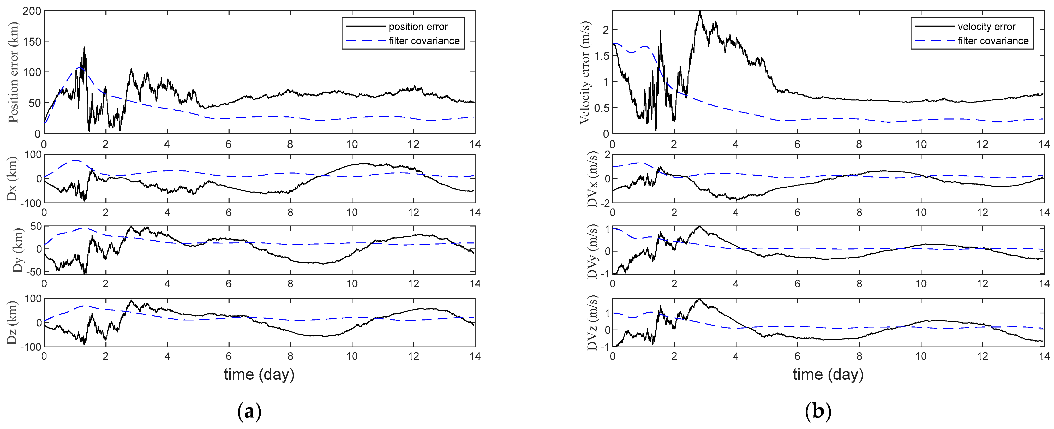
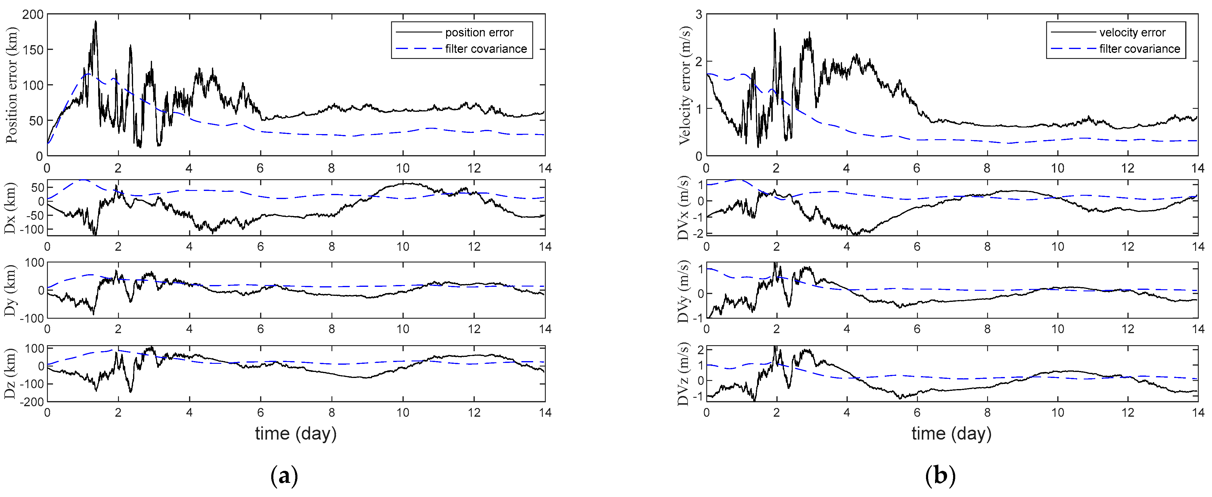
5.2.1. Navigation Results under Different Methods

Figure 3, Figure 4 and Figure 5 and Table 3 show the navigation accuracy under different navigation methods. The estimation error curves in Figure 3 remain stable and convergent within a certain range. The estimation errors in Figure 4 are large and fluctuate sharply. The estimation error curves in Figure 5 gradually converge. It can be seen from Figure 3 and Figure 4 and Table 3 that the sun direction error greatly affects the navigation accuracy of sun direction/solar disk velocity difference integrated navigation. It can be seen from Figure 3 and Figure 5 and Table 3 that the navigation accuracy of the proposed navigation method is similar to those of the sun direction/solar disk velocity difference integrated navigation method without the sun direction error. In summary, the proposed navigation method effectively minimizes the influence of the sun direction error on navigation accuracy.

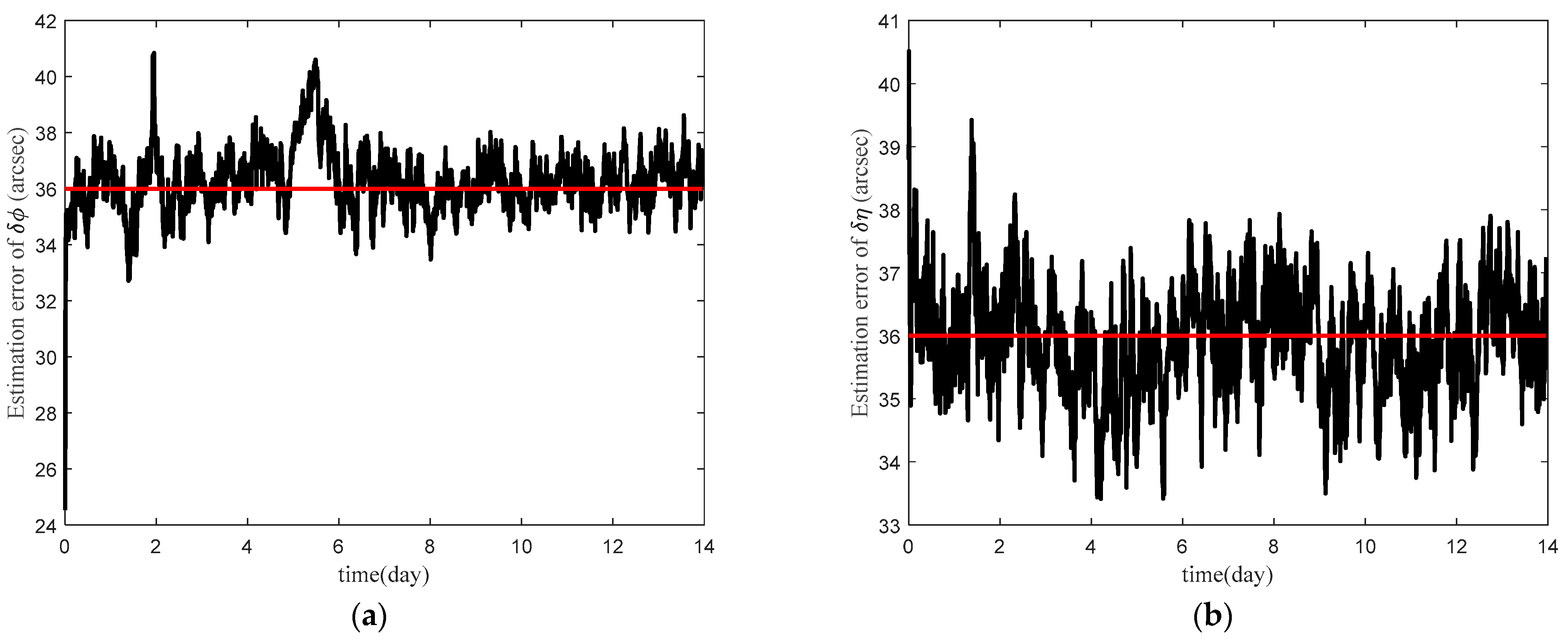
5.2.2. The Estimated Result of Sun Direction Error

The initial values of the solar elevation and azimuth angle errors are set to 3 6 since they come from the sun sensor measurement with the system error. The estimation errors of δ ϕ and δ η are displayed in Figure 6 and Table 4. The estimated error curves of δ ϕ and δ η in Figure 6 converge and fluctuate around 3 6 . The estimated deviation of δ ϕ is 2.03%, and that of δ η is 2.33%. δ ϕ and δ η are well estimated and corrected.

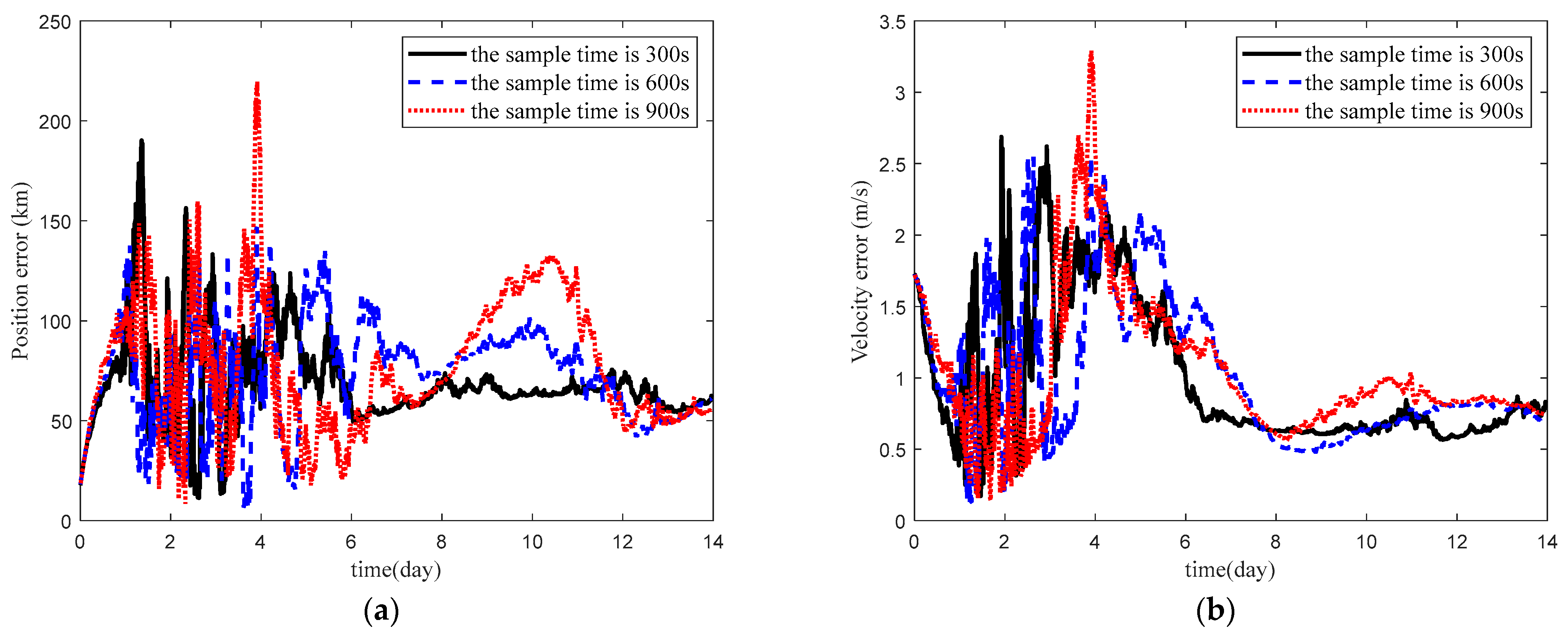
5.2.3. Impact of the Sample Time on Navigation Accuracy

The navigation performance of the proposed navigation method for various sample times is shown in Figure 7 and Table 5. The error estimation curves in Figure 7 are convergent and stable when the sample time is 300 s. The navigation accuracy of the proposed method increases as the sample time decreases. The smaller sample time means a longer run time. In addition, the estimation deviations of δ ϕ and δ η can achieve satisfactory results for various sample times.

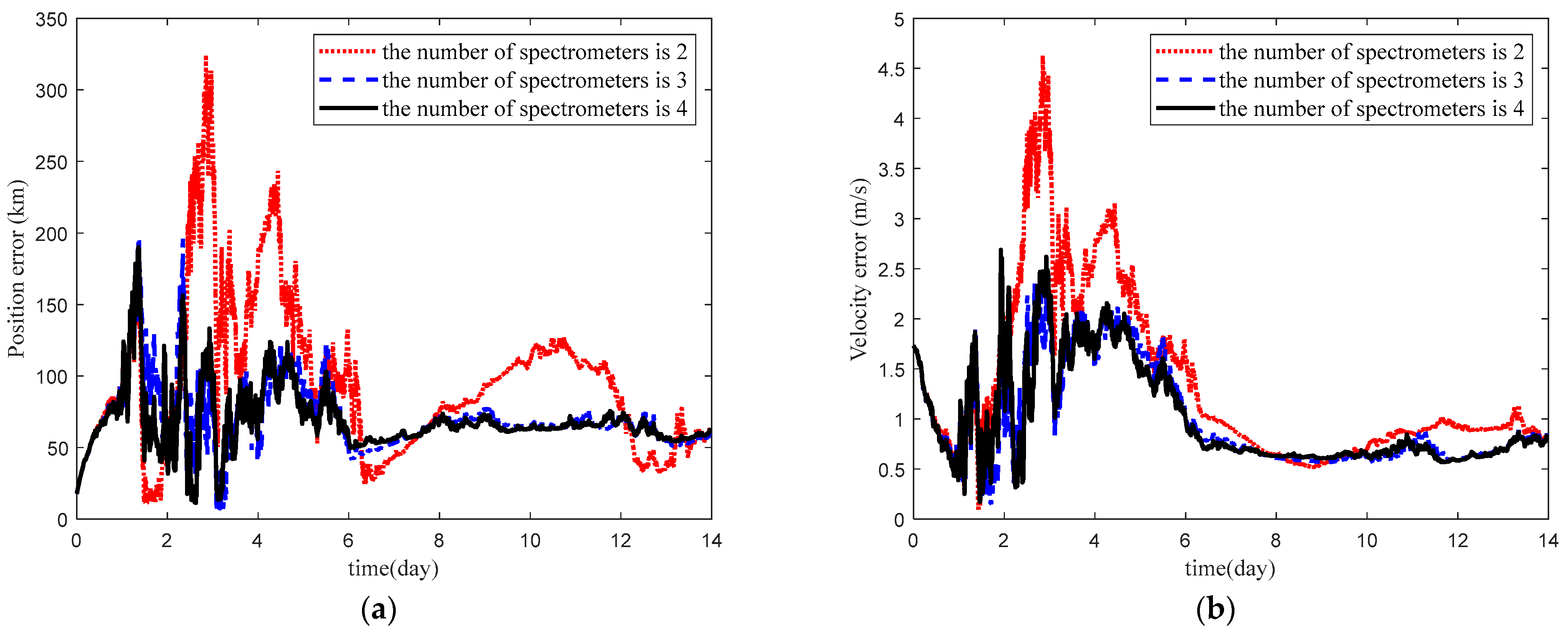
5.2.4. Impact of the Spectrometer Number on Navigation Accuracy

The navigation performance of the proposed navigation method under different spectrometer numbers is shown in Figure 8 and Table 6. As the spectrometer number increases, the navigation accuracy improves. This is because the more spectrometers there are, the more measurement information there is. However, if the number of spectrometers continues to increase, the spacecraft will be overloaded and the spectrometer array will be unstable. In addition, simulation results show that accurate estimation of δ ϕ and δ η is achieved under different spectrometer numbers.

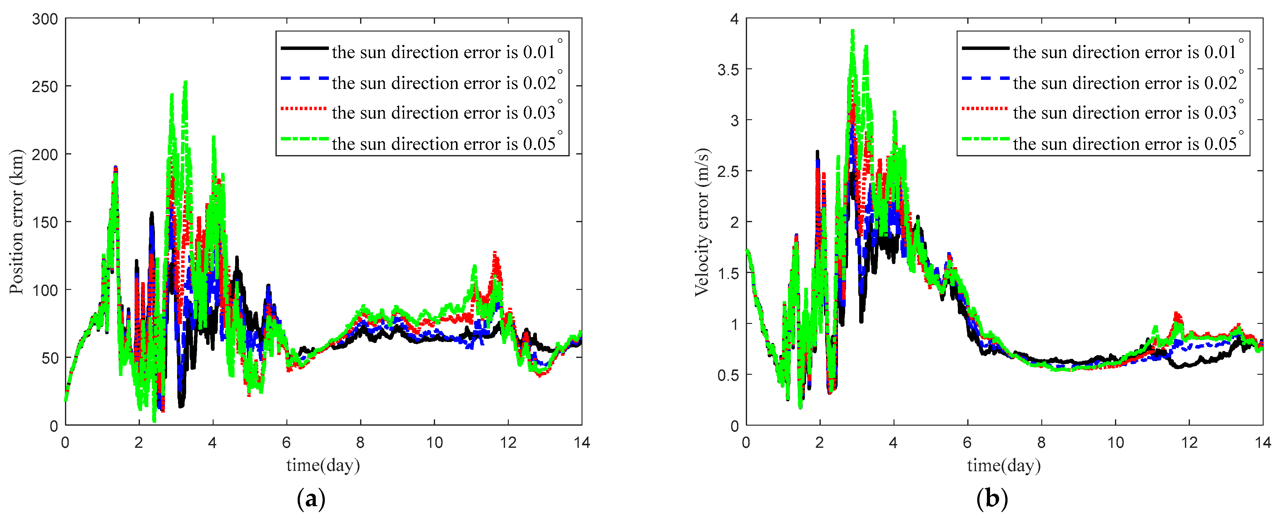
5.2.5. Impact of the Sun Direction Error Value on Navigation Accuracy

The navigation accuracy of the proposed navigation method under different sun direction errors is shown in Figure 9 and Table 7. The navigation performance is significantly impacted by the value of the sun direction error. The sun direction error value increase leads to a deterioration in navigation performance. However, even if the sun direction error is large, the proposed method can still achieve satisfactory navigation performance. The proposed method has a strong anti-interference ability that reduces the sun direction error. The estimation deviations of δ ϕ and δ η increase as the sun direction error value decreases.

6. Conclusions

The proposed method in this article suppresses the impact of the sun direction error on navigation accuracy. The spacecraft acquires direction and distance information to the sun through sun direction and solar disk velocity difference measurements. However, the accuracy of these measurements is affected by the sun direction error. After examining the impact of the sun direction error on these measurements, solar elevation and azimuth angle errors are extended into the state vector. State and measurement models, which consider the errors of the solar elevation and the azimuth angle, are then established. The UKF is utilized to estimate the spacecraft’s navigation information. Simulation results demonstrate that the navigation accuracy of the proposed method is similar to that of sun direction/solar disk velocity difference integrated navigation without the sun direction error. The proposed navigation method effectively mitigates the influence of the sun direction error on navigation accuracy. In detail, the position error and the velocity error of the proposed method are reduced by 97.51% and 96.91% compared with those of the integrated navigation with the sun direction error. In addition, the navigation performance degrades with a longer sample time. Increasing the number of spectrometers improves the navigation performance. Additionally, a larger sun direction error leads to a decrease in navigation performance. The system error suppression method can also provide a reference value for the suppression of other errors in deep space exploration.

Author Contributions

Conceptualization, M.G.; methodology, M.G.; software, M.G. and H.Y.; validation, D.Z.; writing—original draft preparation, M.G. and H.Y.; writing—review and editing, M.G. and M.D.; data curation, C.Z. All authors have read and agreed to the published version of the manuscript.

Funding

This work was funded by the National Natural Science Foundation of China (62003369 and 62203470), the Natural Science Foundation of Hunan Province under Grant 2021JJ40784, and Fundamental Research Funds for the Central Universities: JUSRP123063.

Data Availability Statement

Data sharing is not applicable.

Conflicts of Interest

The authors declare no conflict of interest.

References

  1. Wu, W.; Liu, W.; Qiao, D.; Jie, D. Investigation on the development of deep space exploration. Sci. China-Technol. Sci. 2012, 55, 1086–1091. [Google Scholar] [CrossRef]
  2. Gao, Y.F.; Cheng, B.; Yu, Y.; Lv, J.; Baoyin, H.X. Stability Analysis on the Moon’s Rotation in a Perturbed Binary Asteroid. Mathematics 2022, 10, 3757. [Google Scholar] [CrossRef]
  3. Sebastian, A.; Acedo, L.; Morano, J.A. An orbital model for the Parker Solar Probe mission: Classical vs relativistic effects. Adv. Space Res. 2022, 70, 842–853. [Google Scholar] [CrossRef]
  4. Yang, B.; Jiang, Y.; Li, H.; Jiang, C.; Liu, Y.; Zhan, C.; Jing, H.; Dong, Y. Semi-Analytical Search for Sun-Synchronous and Planet Synchronous Orbits around Jupiter, Saturn, Uranus and Neptune. Mathematics 2022, 10, 2684. [Google Scholar] [CrossRef]
  5. Yue, X.; Schreiner, W.S.; Kuo, Y.-H.; Zhao, B.; Wan, W.; Ren, Z.; Liu, L.; Wei, Y.; Lei, J.; Solomon, S.; et al. The effect of solar radio bursts on the GNSS radio occultation signals. J. Geophys. Res.-Space Phys. 2013, 118, 5906–5918. [Google Scholar] [CrossRef]
  6. Pettit, J.; Randall, C.E.; Marsh, D.R. Effects of the september 2005 Solar Flares and Solar Proton Events on the Middle Atmosphere in WACCM. J. Geophys. Res.-Space Phys. 2018, 123, 5747–5763. [Google Scholar] [CrossRef]
  7. Ahluwalia, H.S. Forecast for sunspot cycle 25 activity. Adv. Space Res. 2022, 69, 794–797. [Google Scholar] [CrossRef]
  8. Popova, E.; Popov, A.I.; Sagdeev, R. Multimode Representation of the Magnetic Field for the Analysis of the Nonlinear Behavior of Solar Activity as a Driver of Space Weather. Mathematics 2022, 10, 1655. [Google Scholar] [CrossRef]
  9. Appenzeller, T. Leaving Jupiter, Ulysses Heads for the Sun’s South Pole. Science 1992, 257, 1478–1479. [Google Scholar] [CrossRef]
  10. Mitchell, J.G.; De Nolfo, G.A.; Hill, M.E. Energetic Electron Observations by Parker Solar Probe/IS circle dot IS during the First Widespread SEP Event of Solar Cycle 25 on 2020 November 29. Astrophys. J. 2021, 919, 119. [Google Scholar] [CrossRef]
  11. Sakshee, S.; Bandyopadhyay, R.; Banerjee, S. MHD-scale anisotropy in solar wind turbulence near the Sun using Parker solar probe data. Mon. Not. R. Astron. Soc. 2022, 514, 1282–1288. [Google Scholar] [CrossRef]
  12. Telloni, D.; Scolini, C.; Mostl, C. Study of two interacting interplanetary coronal mass ejections encountered by Solar Orbiter during its first perihelion passage Observations and modeling. Astron. Astrophys. 2021, 656, A5. [Google Scholar] [CrossRef]
  13. Cesarone, R.J.; Abraham, D.S.; Deutsch, L.J. Prospects for a next-generation deep-space network. Proc. IEEE 2007, 95, 1902–1915. [Google Scholar] [CrossRef]
  14. Gui, M.; Yang, H.; Ning, X.; Xiong, K.; Liu, J.; Dai, M.-Z. Star angle/double-differenced pulse time of arrival integrated navigation method for Jupiter exploration. Adv. Space Res. 2023, 71, 2669–2678. [Google Scholar] [CrossRef]
  15. Turan, E.; Speretta, S.; Gill, E. Autonomous navigation for deep space small satellites: Scientific and technological advances. Acta Astronaut. 2022, 193, 56–74. [Google Scholar] [CrossRef]
  16. Gui, M.; Wei, C.; Wei, Y.; Xiong, K.; Zhang, C.; Dai, M. Parameter-Independent Event-Triggered Implicit UKF for the Celestial Navigation Using Time Delay Measurement. Mathematics 2023, 11, 1952. [Google Scholar] [CrossRef]
  17. Huang, Y.Q.; Ma, X. Autonomous celestial navigation method for a deep-space probe based on angle-constraint aided celestial angle measurement. Sci. Sin.-Phys. Mech. Astron. 2022, 52, 214512. [Google Scholar] [CrossRef]
  18. Hong, J.H.; Park, W.; Ryoo, C.K. An Autonomous Space Navigation System Using Image Sensors. Int. J. Control Autom. Syst. 2021, 19, 2122–2133. [Google Scholar] [CrossRef]
  19. Gui, M.Z.; Zhao, D.J.; Ning, X.L.; Zhang, C.X.; Dai, M.Z. A Time Delay/Star Angle Integrated Navigation Method Based on the Event-Triggered Implicit Unscented Kalman Filter. IEEE Trans. Instrum. Meas. 2021, 70, 1–10. [Google Scholar] [CrossRef]
  20. Chen, P.-T.; Zhou, B.; Speyer, J.L.; Bayard, D.S.; Majid, W.A.; Wood, L.J. Aspects of Pulsar Navigation for Deep Space Mission Applications. J. Astronaut. Sci. 2020, 67, 704–739. [Google Scholar] [CrossRef]
  21. Runnels, J.T.; Gebre-Egziabher, D. Estimator for Deep-Space Position and Attitude Using X-ray Pulsars. IEEE Trans. Aerosp. Electron. Syst. 2021, 57, 2149–2166. [Google Scholar] [CrossRef]
  22. Liu, J.; Li, Y.Y.; Ning, X.L.; Chen, X.; Kang, Z.W. Modeling and analysis of solar Doppler difference bias with arbitrary rotation axis. Chin. J. Aeronaut. 2020, 33, 3331–3343. [Google Scholar] [CrossRef]
  23. Ning, X.L.; Gui, M.Z.; Fang, J.C.; Dai, Y.; Liu, G. A Novel Differential Doppler Measurement-Aided Autonomous Celestial Navigation Method for Spacecraft During Approach Phase. IEEE Trans. Aerosp. Electron. Syst. 2017, 53, 587–597. [Google Scholar] [CrossRef]
  24. Howard, R.; Harvey, J. Spectroscopic determinations of solar rotation. Sol. Phys. 1969, 12, 23–51. [Google Scholar] [CrossRef]
  25. Ning, X.L.; Chao, W.; Huang, Y.L.; Wu, W.R.; Fang, J.C. Spacecraft Autonomous Navigation Using the Doppler Velocity Differences of Different Points on the Solar Disk. IEEE Trans. Aerosp. Electron. Syst. 2020, 56, 4615–4625. [Google Scholar] [CrossRef]
  26. Ning, X.L.; Huang, Y.L.; Chao, W. Integrated navigation of solar disk velocity difference and sun direction for spacecraft. Acta Astronaut. Astronaut. Sin. 2020, 41, 271–280. (In Chinese) [Google Scholar]
  27. Yang, P.; Xie, L.; Liu, J.L. Simultaneous celestial positioning and orientation for the lunar rover. Aerosp. Sci. Technol. 2014, 34, 45–54. [Google Scholar] [CrossRef]
  28. Hotta, H.; Kusano, K. Solar differential rotation reproduced with high-resolution simulation. Nat. Astron. 2021, 5, 1100–1102. [Google Scholar] [CrossRef]
  29. Xie, N.; Theuwissen, A.J.P. A Miniaturized Micro-Digital Sun Sensor by Means of Low-Power Low-Noise CMOS Imager. IEEE Sens. J. 2014, 14, 96–103. [Google Scholar] [CrossRef]
  30. Jing, C.Q.; Liang, T.; Lei, Q.J. A New Kind of Miniature Sun Sensor Design. In Proceedings of the 2016 IEEE International Conference on Electronic Information and Communication Technology, Harbin, China, 20–22 August 2016; pp. 219–222. [Google Scholar]
  31. Wei, M.S.; Xing, F.; Li, B.; You, Z. Investigation of Digital Sun Sensor Technology with an N-Shaped Slit Mask. Sensors 2011, 11, 9764–9777. [Google Scholar] [CrossRef]
  32. Xie, R.; Wang, B.; Li, S.; He, Y.; Wu, D.; Sun, S. Method and verification of accuracy improvement of digital sun sensor system. Chin. Space Sci. Technol. 2022, 1–6. (In Chinese) [Google Scholar]
  33. Rauh, A.; Wirtensohn, S.; Hoher, P.; Reuter, J.; Jaulin, L. Reliability Assessment of an Unscented Kalman Filter by Using Ellipsoidal Enclosure Techniques. Mathematics 2022, 10, 3011. [Google Scholar] [CrossRef]
Figure 1. The spectrometer array [25].
Mathematics 11 03716 g001
Figure 2. The diagram of the solar disks obtained with and without sun direction error.
Mathematics 11 03716 g002
Figure 3. Integrated navigation without sun direction error. (a) Position error. (b) Velocity error.
Mathematics 11 03716 g003
Figure 4. Integrated navigation with sun direction error. (a) Position error. (b) Velocity error.
Mathematics 11 03716 g004
Figure 5. Augmented state integrated navigation. (a) Position error. (b) Velocity error.
Mathematics 11 03716 g005
Figure 6. Estimated result of sun direction error. (a) Solar elevation angle error. (b) Solar azimuth angle error.
Mathematics 11 03716 g006
Figure 7. Navigation accuracy for various sample time. (a) Position error. (b) Velocity error.
Mathematics 11 03716 g007
Figure 8. Navigation accuracy under different number of spectrometers. (a) Position error. (b) Velocity error.
Mathematics 11 03716 g008
Figure 9. Navigation accuracy under different sun direction errors. (a) Position error. (b) Velocity error.
Mathematics 11 03716 g009
Table 1. Orbital parameter.
ParameterValue
Semi-major axis ( a ) 1.06955 × 10 7 km
Eccentricity ( e )0.02
Orbital inclination ( i ) 60 °
Right ascension of the ascending node ( Ω ) 0 °
Argument of perigee ( ω ) 0 °
Table 2. Parameter of filter.
ParameterValue
Initial state error δ X 0 = [ 10   km , 10   km , 10   km , 1   m / s , 1   m / s , 1   m / s , 3 6 , 3 6 ] T
Initial state covariance P = d i a g [ 10 8 m 2 , 10 8 m 2 , 10 8 m 2 , 1 ( m / s ) 2 , 1 ( m / s ) 2 , 1 ( m / s ) 2 , 10 7 , 10 7 ] T
Process noise covariance Q = 2 × d i a g [ 10 1 m 2 , 10 1 m 2 , 10 1 m 2 , 10 6 ( m / s ) 2 , 10 6 ( m / s ) 2 , 10 6 ( m / s ) 2 , 10 12 , 10 12 ] T
Measurement noise covariance R = d i a g [ 1 ( m / s ) 2 , 1 ( m / s ) 2 , 1 ( m / s ) 2 , 1 ( m / s ) 2 , 1 ( m / s ) 2 , 1 ( m / s ) 2 , ( 5 ) 2 , ( 5 ) 2 ]
Filter period300 s
Table 3. Navigation results under different methods.
MethodPosition Error (km)Velocity Error (m/s)
Integrated navigation without sun direction error60.140.90
Integrated navigation with sun direction error2750.5732.01
Augmented state integrated navigation68.540.99
Table 4. Estimated results of sun direction error.
ErrorsTrue ErrorMean Estimation Error
δ ϕ 3 6 36.837 0
δ η 3 6 35.267 7
Table 5. Navigation accuracy for various sample times.
Sample Time
(s)
Position Error
(km)
Velocity Error
(m/s)
Estimation   Deviation   of   δ ϕ Estimation   Deviation   of   δ η Run Time
(s)
30068.540.992.33%2.03%16.796
60072.651.012.38%1.94%10.437
90077.131.032.54%2.31%7.670
Table 6. Navigation accuracy under different numbers of spectrometers.
The Number of SpectrometersPosition Error
(km)
Velocity Error
(m/s)
Estimation   Deviation   of   δ ϕ Estimation   Deviation   of   δ η
295.941.333.60%3.43%
370.480.992.14%1.96%
468.540.992.33%2.03%
Table 7. Navigation accuracy under different sun direction errors.
Sun Direction Error Value
(Degree)
Position Error
(km)
Velocity Error
(m/s)
Estimation   Deviation   of   δ ϕ Estimation   Deviation   of   δ η
0.0168.540.992.33%2.03%
0.0270.591.041.17%1.08%
0.0376.151.110.87%0.85%
0.0578.151.140.53%0.56%
Disclaimer/Publisher’s Note: The statements, opinions and data contained in all publications are solely those of the individual author(s) and contributor(s) and not of MDPI and/or the editor(s). MDPI and/or the editor(s) disclaim responsibility for any injury to people or property resulting from any ideas, methods, instructions or products referred to in the content.

