Article

High-Order Modeling, Zeroing Dynamics Control, and Perturbations Rejection for Non-Linear Double-Holding Water Tank

1
School of Computer Science and Engineering, Sun Yat-sen University, Guangzhou 510006, China
2
National Key Laboratory of Science and Technology on Reliability Physics and Application of Electronic Component, The Fifth Electronics Research Institute of the Ministry of Industry and Information Technology, Guangzhou 511370, China
3
School of Intelligent Systems Engineering, Shenzhen Campus of Sun Yat-sen University, Shenzhen 518057, China
*
Author to whom correspondence should be addressed.
Mathematics 2023, 11(13), 2989; https://doi.org/10.3390/math11132989
Submission received: 2 June 2023 / Revised: 24 June 2023 / Accepted: 27 June 2023 / Published: 4 July 2023

Abstract

:
The double-holding water tank system is a common non-linear control system that plays a crucial role in process control in the chemical industry. It consists of two cylindrical glass containers: the preset tank and the main tank. The main challenge in controlling this system is adjusting the main control valve to ensure that the actual liquid level of the main tank tracks the desired liquid level. This paper explores the zeroing dynamics (ZD) method and its application in tracking control. A non-linear model is developed for the double-holding water tank system, and the ZD method is used to design an effective controller (called the ZD controller) for tracking control. Additionally, the robustness of the double-holding water tank system in the presence of time-varying perturbations is investigated. In order to substantiate the effectiveness and robustness of the ZD controller, simulation experiments on four different tracking trajectories corresponding to four different practical situations, as well as an extra simulation experiment considering time-varying perturbations, are conducted. Furthermore, a comparative simulation experiment based on the backstepping method is conducted. The presented results successfully illustrate the feasibility and effectiveness of the ZD method for the tracking control of double-holding water tank systems.

1. Introduction

As a non-linear system, double-holding water tanks are an important control object in chemical production processes [1,2,3]. The double-holding water tank system comprises two self-balancing tanks connected in series—namely, the preset tank and the main tank—which are required to control the liquid level of the main tank.
Given the important role of the double-holding water tank, many experts have studied methods for controlling the liquid level [2,4,5,6,7,8]. An application of fuzzy control theory to the liquid level system has been discussed, in which a fuzzy self-tuning proportional–integral–derivative (PID) controller is utilized [4]. Another method to control the double-tank system has been proposed by obtaining the theoretical PID parameters through measurement of the characteristic curves of the water level [2]. Considering the tank level control process, an adaptive setting method combined with a genetic algorithm has been applied in order to optimize the parameters of the PID controller [5]. Another method based on the combination of an inverse system and a PID controller has been proposed for level control of double-holding water tanks [6]. Almost all of the above methods are based on PID control methods, and it is well-known that the performance of PID controllers depends on the selection of parameters. However, parameter selection is often a difficult task in practical applications, due to the uncertainty and change of controlled objects. Moreover, PID controllers are sensitive to interference such as system parameter changes and measurement noise, which may lead to system instability or reduced control.
The robustness [9,10,11] of a control system refers to the ability of that control system to maintain stability and meet the performance indicators in the face of model uncertainty, external interference, and/or system changes. The robustness of a control system is a very important aspect in its design. In practical applications, control systems are often faced with a variety of uncertainties and perturbations, such as sensor measurement error, actuator non-linearity, and external perturbations. These factors may lead to the degradation of performance or failure of the control system. Therefore, the robustness of a given system must be investigated, as it is the key to survival in the event of abnormal and dangerous situations. Many researchers have studied numerous methods to enhance the robustness of systems [11,12,13,14,15,16,17,18,19]; for example, a discrete time-zeroing neural algorithm has been proposed for the solution of a system of linear equations with the aid of control techniques. To lay a foundation for theoretical analyses, this proposed algorithm with non-linearity was converted into a second-order linear system plus a residual term [12]. In the same year, differently modified zeroing neural dynamics models were proposed, analyzed, and investigated for solution of the time-varying reciprocal problem with inherent tolerance to noise [13]. The robustness and stabilization of uncertain neutral singular systems has been studied, and a new stability criterion for the differential operator has been developed [14]. A finite time-convergent method with sufficient noise rejection capability to endure perturbations and solve dynamic non-linear equations in finite time has also been proposed. In theory, the finite time convergence and noise rejection properties of this proposed method were rigorously proved [15].
The double-holding water tank belongs to the class of higher-order systems. These systems [20,21,22,23,24,25] are usually complex systems composed of multiple interrelated subsystems, among which multi-level interactions and dependencies exist. Higher-order systems may include multiple complex physical, biological, or social components, with complex feedback mechanisms existing among these components. Therefore, higher-order systems often show non-linear and unpredictable properties. Fortunately, many control schemes, such as backstepping control [20,21,22,23], block control [26,27], sliding mode control [24,25], and so on, are also suitable for such systems. Sliding mode control involves complex interactions between multiple tissues and neurons, which increases the complexity and difficulty of the control system. Meanwhile, backstepping control requires iterative computation, which may result in high computational costs. This can pose a limitation for real-time applications with high real-time control requirements. To date, such methods have not been applied to double-holding water tank systems.
In recent years, zeroing dynamics (ZD) has been proposed and investigated for the solution of time-varying problems. Due to its advantages in terms of convergence and accuracy, the ZD method has been successfully extended to various areas, including automatic control, robotics, and numerical computation [8,28,29,30,31,32,33,34,35]. As a powerful method, ZD has been substantiated for the tracking of non-linear systems. For example, a new kind of method based on ZD has been introduced for tracking control; in particular, to control the concentration and liquid level of the agitator tank to achieve the desired trajectories [8]. Inspired by the ZD method, a simple and effective ZD-achieving controller has been designed for the synchronization of chaotic systems under the simultaneous existence of parameter perturbations, model uncertainty, and external perturbations [29]. Furthermore, the ZD method has been substantiated as an effective and accurate method for solving non-linear equation systems, particularly time-varying non-linear systems of equations [30]. Considering the feasibility and effectiveness of the ZD method, we believe that it has high potential for utilization in the tracking control of non-linear double-holding water tank systems.
The remainder of this paper is organized as follows. Section 2 introduces the structure of the double-holding water tank system and its dynamic process, based on which the model of the double-holding water tank system is constructed. Section 3 introduces the ZD method for the double-holding water tank system. Furthermore, the corresponding ZD controller is designed and the theoretical analysis of the convergence property of the double-holding water tank system equipped with ZD controller is provided. Section 4 investigates the robustness of the double-holding water tank system equipped with the ZD controller in the presence of time-varying perturbations. In Section 5, simulations (including the comparative simulation) are performed to illustrate the feasibility and effectiveness of the ZD controllers for liquid level tracking control of a double-holding water tank system. Finally, Section 6 concludes the paper. Before ending this section, it is worth pointing out the main contributions of this paper, as follows:
  • The fundamental structure of the non-linear double-holding water tank system is given, and a non-linear model is constructed for the double-holding water tank system.
  • Based on the ZD method, a design procedure for the ZD controller is detailed; furthermore, the theoretical analysis of the convergence property of the double-holding water tank system equipped with ZD controller is provided.
  • The robustness of the double-holding water tank system equipped with the ZD controller in the presence of time-varying perturbations and a theoretical analysis of its bounded property is studied.
  • Simulations especially those including perturbations are carried out with four different tracking trajectories. Moreover, for comparison, the tracking control of the double-holding water tank equipped with a backstepping controller is conducted, in order to further illustrate the performance of the ZD method. These simulation results verify the validity of theoretical analyses and the effectiveness of the proposed ZD controller.

2. Non-Linear Modeling and Problem Formulation

In this section, the non-linear double-holding water tank system is introduced and a corresponding model is constructed.

2.1. Non-Linear Double-Holding Water Tank System

The fundamental structure of the non-linear double-holding water tank system [1] is shown in Figure 1. From the figure, it can be observed that the double-holding water tank system mainly consists of two cylindrical glass containers: the preset tank and main tank, denoted by T 1 and T 2 , respectively. The preset tank T 1 and main tank T 2 are connected by the middle-control valve r 1 . Liquid flows into the preset tank T 1 by regulating the main-control valve u ( t ) , then flows into the main tank T 2 through the middle-control valve r 1 , and finally flows out through the discharge-control valve r 2 .
The quantities of liquid flowing through u ( t ) , r 1 , and r 2 are denoted as Q u ( t ) , Q 1 ( t ) , and Q 2 ( t ) , respectively. It is worth pointing out that the main-control valve u ( t ) is self-regulating, while the middle-control valve r 1 and discharge-control valve r 2 can be manually regulated. The bottom areas of the preset tank T 1 and main tank T 2 are denoted as C 1 and C 2 , respectively, while the liquid levels of the preset tank T 1 and main tank T 2 are h 1 ( t ) and h 2 ( t ) .
The main purpose of the paper is to design an effective controller to control the liquid level in the double-holding water tank system. It is worth noting that the double tank equipment can be used not only for the liquid level control experiments considering a single water tank, but also for the double-holding water tank liquid level control experiments. In this paper, we mainly focus on the latter. Note that the input is the liquid quantity Q u ( t ) , while the output is the liquid level h 2 ( t ) of the main tank T 2 .

2.2. Non-Linear Modeling and Problem Formulation

In this subsection, the mathematical model of the double-holding water tank system is investigated and provided. Based on the flow balance principle [36], we have
Q u ( t ) Q 1 ( t ) = C 1 h ˙ 1 ( t ) , Q 1 ( t ) Q 2 ( t ) = C 2 h ˙ 2 ( t ) ,
where h ˙ 1 ( t ) and h ˙ 2 ( t ) denote the liquid flow rates of the preset tank T 1 and main tank T 2 , respectively; while C 1 and C 2 are the bottom areas of the preset tank T 1 and main tank T 2 , respectively.
According to the fluid motion Equation [36], we thus have
Q u ( t ) = k u u ( t ) , Q 1 ( t ) = k 1 h 1 ( t ) , Q 2 ( t ) = k 2 h 2 ( t ) ,
where k u is the flow coefficient of the regulating main-control valve u ( t ) , and k 1 and k 2 are the resistance coefficients of the valve section with certain valve opening, which are positive constants associated with the acceleration due to gravity and cross-sectional areas of the communicating tubes.
Substituting (2) into (1), we obtain
k 1 h 1 ( t ) k 2 h 2 ( t ) = C 2 h ˙ 2 ( t ) ,
where k 1 and k 2 are as defined in (2).
Solving Equation (3), we have
h 1 ( t ) = k 2 h 2 ( t ) + C 2 h ˙ 2 ( t ) k 1 2 .
From Equation (1), we obtain
Q u ( t ) Q 2 ( t ) = C 1 h ˙ 1 ( t ) + C 2 h ˙ 2 ( t ) .
Substituting (2) and (4) into (5), we thus have
k u u ( t ) k 2 h 2 ( t ) = C 1 k 2 2 k 1 2 h ˙ 2 ( t ) + 2 C 1 C 2 2 k 1 2 h ˙ 2 ( t ) h ¨ 2 ( t ) + 2 C 1 C 2 k 2 k 1 2 h 2 ( t ) h ¨ 2 ( t ) + C 1 C 2 k 2 k 1 2 ( h ˙ 2 ( t ) ) 2 h 2 ( t ) + C 2 h ˙ 2 ( t ) ,
where h ¨ 2 ( t ) denotes the liquid flow acceleration for the main tank T 2 . For the sake of formulation convenience, some positive constants are introduced; namely, a 1 ,   a 2 ,   a 3 ,   a 4 ,   a 5 and a 6 , where
a 1 = C 1 k 2 2 k 1 2 , a 2 = 2 C 1 C 2 2 k 1 2 , a 3 = C 1 C 2 k 2 k 1 2 , a 4 = C 2 , a 5 = k 2 , a 6 = k u .
Then, we obtain
h ¨ 2 ( t ) = 1 a 2 h ˙ 2 ( t ) + 2 a 3 h 2 ( t ) ( a 6 u ( t ) a 3 ( h ˙ 2 ( t ) ) 2 h 2 ( t ) ( a 1 + a 4 ) h ˙ 2 ( t ) a 5 h 2 ( t ) ) .
According to Equation (6), the state equation of the double-holding water tank system can be expressed as follows:
x ˙ 1 ( t ) = x 2 ( t ) , x ˙ 2 ( t ) = 1 a 2 x 2 ( t ) + 2 a 3 x 1 ( t ) ( a 6 u ( t ) a 3 x 2 2 ( t ) x 1 ( t ) ( a 1 + a 4 ) x 2 ( t ) a 5 x 1 ( t ) ) ,
where x 1 ( t ) = h 2 ( t ) and x 2 ( t ) = h ˙ 2 ( t ) are selected as state variables, and x ˙ 1 ( t ) and x ˙ 2 ( t ) are the time derivatives of x 1 ( t ) and x 2 ( t ) , respectively (in practical applications, x 1 ( t ) > 0 ).
The mathematical model of the double-holding water tank system was considered in our further investigations.

3. ZD Method for Double-Holding Water Tank System

This section is divided into two subsections. First, based on ZD method, an effective controller is designed. Then, the theoretical analysis of the convergence property of the designed controller is detailed.

3.1. Controller Design Based on ZD Method

In order to construct a controller for the double-holding water tank system, the ZD method is exploited two times. In particular, three steps were adopted to develop the ZD controller.
In the first step, following the ZD method [28,30,31], we define the first ZD formula as follows. Note that the output is the liquid level h 2 ( t ) of the main tank T 2 , which is denoted as y ( t ) generally. We define the first error function as
v 1 ( t ) = y ( t ) y d ( t ) = x 1 ( t ) y d ( t ) ,
where x 1 ( t ) = h 2 ( t ) is the state defined in (7) and y d ( t ) denotes the desired output (i.e., h 2 d ( t ) ).
Then, the ZD design formula is employed:
v ˙ 1 ( t ) = λ 1 v 1 ( t ) ,
where λ 1 > 0 R denotes a positive design parameter used to scale the convergence rate of the ZD solution. Substituting (8) into (9), we have
x ˙ 1 ( t ) y ˙ d ( t ) = λ 1 ( x 1 ( t ) y d ( t ) ) .
In the second step, in order to generate a direct relationship between the output y ( t ) and the input u ( t ) , we define the second error function as
v 2 ( t ) = v ˙ 1 ( t ) + λ 1 v 1 ( t ) = x ˙ 1 ( t ) y ˙ d ( t ) + λ 1 ( x 1 ( t ) y d ( t ) ) .
Afterwards, applying the second ZD formula
v ˙ 2 ( t ) = λ 2 v 2 ( t ) ,
where λ 2 > 0 R is another positive design parameter.
We have x ¨ 1 ( t ) y ¨ d ( t ) + λ 1 ( x ˙ 1 ( t ) y ˙ d ( t ) ) = λ 2 x ˙ 1 ( t ) y ˙ d ( t ) + λ 1 ( x 1 ( t ) y d ( t ) ) . Substituting x ˙ 1 ( t ) = x 2 ( t ) in Equation (7) into the above equation, we thus have
x ˙ 2 ( t ) y ¨ d ( t ) + λ 1 ( x 2 ( t ) y ˙ d ( t ) ) = λ 2 x 2 ( t ) y ˙ d ( t ) + λ 1 ( x 1 ( t ) y d ( t ) ) .
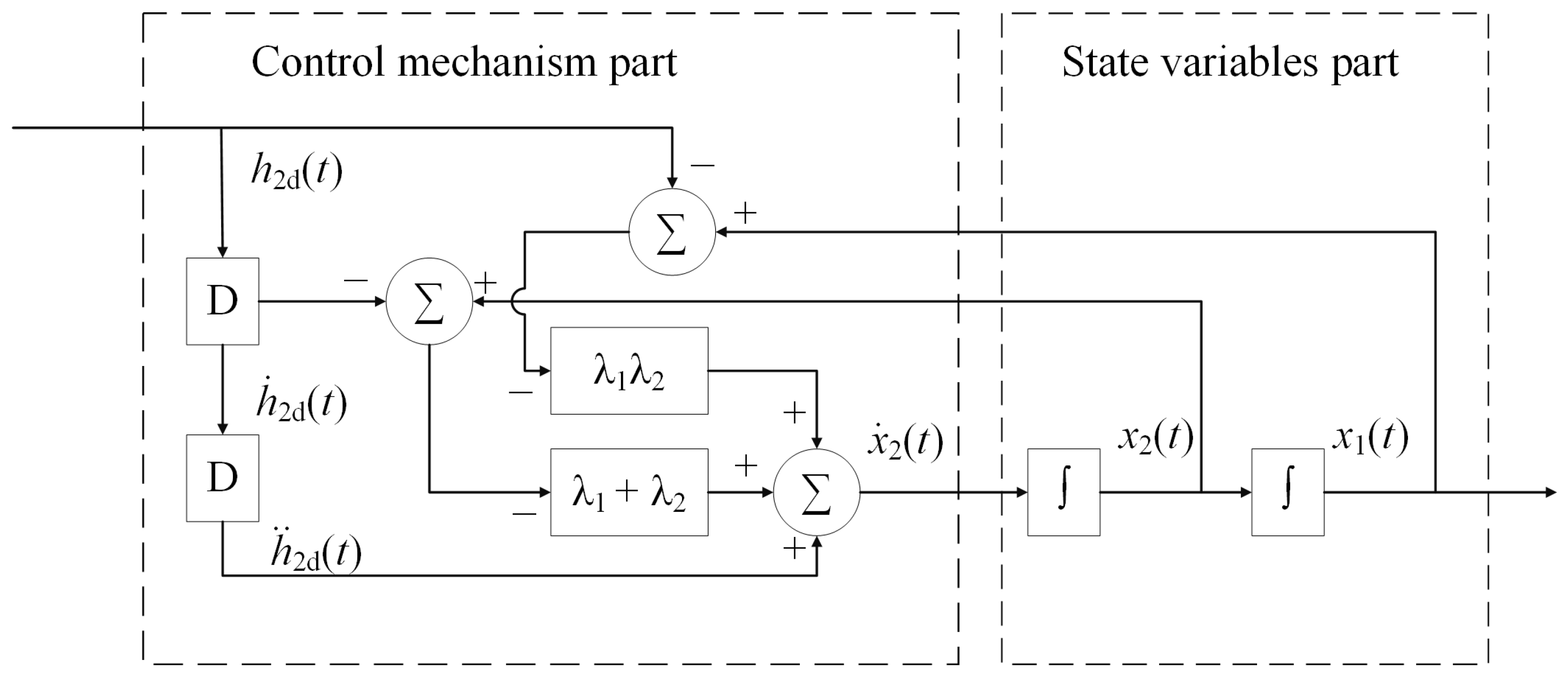
The detailed realization of (12) is shown in Figure 2.
Finally, for the sake of simplicity, letting
f 1 ( t ) = y ¨ d ( t ) ( λ 1 + λ 2 ) ( x 2 ( t ) y ˙ d ( t ) ) λ 1 λ 2 ( x 1 ( t ) y d ( t ) ) , f 2 ( t ) = a 2 x 2 ( t ) , f 3 ( t ) = ( a 1 + a 4 ) x 2 ( t ) , f 4 ( t ) = 2 a 3 x 1 ( t ) , f 5 ( t ) = a 5 x 1 ( t ) ,
where f 1 ( t ) , f 2 ( t ) , f 3 ( t ) , f 4 ( t ) and f 5 ( t ) are functions of the state variables, and combining Equations (7) and (11), we obtain the ZD controller, in the form of u ( t ) , as:
u ( t ) = f 1 ( t ) f 2 ( t ) + f 3 ( t ) a 6 + f 1 ( t ) f 4 ( t ) + f 5 ( t ) + a 3 x 2 2 ( t ) a 6 x 1 ( t ) .
Through the above steps, a concise ZD controller was obtained for tracking control of the double-holding water tank system (7). Notably, this controller design strategy can be applied to many other non-linear systems.

3.2. Theoretical Analysis of Convergence Property

Based on the above controller, this subsection details the theoretical analysis of the convergence property for the double-holding water tank system (7) equipped with the ZD controller (13).
Theorem 1.
For a continuously differentiable and bounded desired trajectory  y d ( t ) , starting from any bounded initial state  [ x 1 ( 0 ) , x 2 ( 0 ) ] , the tracking error  ε ( t ) = x 1 ( t ) y d ( t )  of the double-holding water tank system (7) equipped with the ZD controller (13) converges to zero exponentially.
Proof of Theorem 1.
According to the design procedure of the ZD controller, one can readily find that
v ˙ 2 ( t ) + λ 2 v 2 ( t ) = 0 .
The solution to (14) is obtained as
v 2 ( t ) = v 2 ( 0 ) exp ( λ 2 t ) .
Substituting the solution into (10), we obtain that
v ˙ 1 ( t ) + λ 1 v 1 ( t ) = v 2 ( 0 ) exp ( λ 2 t ) .
According to the evaluation method of the first-order non-linear differential equation, the solution to (15) is obtained as
v 1 ( t ) = v 1 ( 0 ) exp ( λ 1 t ) + exp ( λ 1 t ) 0 t ( exp ( λ 1 τ ) v 2 ( 0 ) exp ( λ 2 τ ) ) d τ = v 1 ( 0 ) exp ( λ 1 t ) + v 2 ( 0 ) exp ( λ 1 t ) 0 t exp ( λ 1 τ λ 2 τ ) d τ .
If λ 1 λ 2 , we further have
v 1 ( t ) = v 1 ( 0 ) exp ( λ 1 t ) + v 2 ( 0 ) exp ( λ 1 t ) exp ( λ 1 t λ 2 t ) 1 λ 1 λ 2 = v 1 ( 0 ) v 2 ( 0 ) λ 1 λ 2 exp ( λ 1 t ) + v 2 ( 0 ) λ 1 λ 2 exp ( λ 2 t ) = b 1 exp ( λ 1 t ) + b 2 exp ( λ 2 t )
where b 1 = v 1 ( 0 ) v 2 ( 0 ) / ( λ 1 λ 2 ) and b 2 = v 2 ( 0 ) / ( λ 1 λ 2 ) , which are both constants.
Then, we obtain
| v 1 ( t ) | 2 max { | b 1 | , | b 2 | } exp ( ξ 1 t ) = d 1 exp ( ξ 1 t ) ,
where d 1 = 2 max { | b 1 | , | b 2 | } 0 and ξ 1 = min { λ 1 , λ 2 } > 0 .
If λ 1 = λ 2 , then v 1 ( t ) can be further rewritten as
v 1 ( t ) = v 1 ( 0 ) exp ( λ 1 t ) + v 2 ( 0 ) exp ( λ 1 t ) 0 t exp ( λ 1 τ λ 2 τ ) d τ = ( v 1 ( 0 ) + v 2 ( 0 ) t ) exp ( λ 1 t ) = ( b 3 + b 4 t ) exp ( λ 1 t ) ,
where b 3 = v 1 ( 0 ) and b 4 = v 2 ( 0 ) , which are also both constants. It can be generalized, from the proof of Lemma 1 in [37], that there exist μ > 0 and β > 0 such that
b 4 exp ( λ 1 t ) t μ exp ( β t ) .
Thus, we have
v 1 ( t ) = ( b 3 + b 4 t ) exp ( λ 1 t ) b 3 exp ( λ 1 t ) + μ exp ( β t ) .
Then, we obtain that
| v 1 ( t ) | 2 max { | b 3 | , | μ | } exp ( ξ 2 t ) = d 2 exp ( ξ 2 t ) ,
where d 2 = 2 max { | b 3 | , | μ | } 0 and ξ 2 = min { λ 1 , β } > 0 .
Following the analysis of the above two situations, it can be found that the tracking error ε ( t ) = x 1 ( t ) y d ( t ) = v 1 ( t ) of the double-holding water tank system (7) equipped with the ZD controller (13) possesses exponential convergence performance.
The proof is thus completed. □
Remark 1.
We can choose suitable values for the design parameters, according to the practical situation, in order to obtain a relatively low computing time.

4. Robustness of Double-Holding Water Tank System Based on the ZD Method

To lay a foundation for further investigation of the robustness of the double-holding water tank system (7) equipped with the ZD controller (13) under unknown perturbations, we utilize the following equation:
x ¨ 1 ( t ) y ¨ d ( t ) + λ 1 ( x ˙ 1 ( t ) y ˙ d ( t ) ) = λ 2 x ˙ 1 ( t ) y ˙ d ( t ) + λ 1 ( x 1 ( t ) y d ( t ) ) + w ( t ) .
For further investigation, the above equation can be rewritten as
ε ¨ ( t ) + λ 1 ε ˙ ( t ) = λ 2 ( ε ˙ ( t ) + λ 1 ε ( t ) ) + w ( t ) .
Rearranging the above equation, we have
ε ¨ ( t ) + ( λ 1 + λ 2 ) ε ˙ ( t ) + λ 1 λ 2 ε ( t ) w ( t ) = 0 ,
where w ( t ) R denotes the perturbations, such as time-varying perturbations, bounded perturbations, or their superposition. Note that any pre-processing for perturbation rejection may consume extra time, possibly violating the requirement of real-time computation. The proposed ZD controller is able to suppress various kinds of perturbations. Considering time-varying bounded perturbations, we have the following theorem.
Theorem 2.
Considering bounded time-varying perturbations on the double-holding water tank system (7) equipped with the ZD controller (13), the tracking error ε ( t ) of the double-holding water tank system is bounded under the time-varying bounded perturbation w ( t ) = σ ( t ) R . In addition, the steady-state tracking error is bounded by max 0 τ < | σ ( τ ) | / ( λ 1 λ 2 ) . Furthermore, the bound of the steady-state absolute tracking error lim t sup | ε ( t ) | is in inverse proportion to λ 1 λ 2 , and the steady-state tracking error can be made arbitrarily small by increasing λ 1 λ 2 to be sufficiently large.
Proof of Theorem 2.
With the time-varying bounded perturbation w ( t ) = σ ( t ) R , Equation (17) can be rewritten as
ε ¨ ( t ) + ( λ 1 + λ 2 ) ε ˙ ( t ) + λ 1 λ 2 ε ( t ) σ ( t ) = 0 .
Substituting ε ( t ) = v 1 ( t ) and v 2 ( t ) = x ˙ 1 ( t ) y ˙ d ( t ) + λ 1 ( x 1 ( t ) y d ( t ) ) = v ˙ 1 ( t ) + λ 1 v 1 ( t ) into the above equation, we have
v ˙ 2 ( t ) + λ 2 v 2 ( t ) = σ ( t ) .
The solution to (18) can be obtained as
v 2 ( t ) = v 2 ( 0 ) exp ( λ 2 t ) + exp ( λ 2 t ) 0 t ( exp ( λ 2 τ ) σ ( τ ) ) d τ .
From the triangle inequality, we have
| v 2 ( t ) | | v 2 ( 0 ) exp ( λ 2 t ) | + exp ( λ 2 t ) 0 t ( exp ( λ 2 τ ) | σ ( τ ) | ) d τ .
Considering that σ ( t ) is bounded, we further have
| v 2 ( t ) | | v 2 ( 0 ) exp ( λ 2 t ) | + exp ( λ 2 t ) 0 t exp ( λ 2 τ ) d τ max 0 τ t | σ ( τ ) | .
Finally, we obtain
lim t sup | v 2 ( t ) | = max 0 τ < | σ ( τ ) | λ 2 .
Therefore, v 2 ( t ) is bounded.
Letting ψ ( t ) = v 2 ( t ) , we obtain the following equation with bounded ψ ( t ) . Note that v 2 ( t ) = x ˙ 1 ( t ) y ˙ d ( t ) + λ 1 ( x 1 ( t ) y d ( t ) ) = v ˙ 1 ( t ) + λ 1 v 1 ( t ) . Then, we have
v ˙ 1 ( t ) + λ 1 v 1 ( t ) = ψ ( t ) ,
where λ 1 > 0 R was defined in (9).
The solution to (19) can be obtained as
v 1 ( t ) = v 1 ( 0 ) exp ( λ 1 t ) + exp ( λ 1 t ) 0 t ( exp ( λ 1 τ ) ψ ( τ ) ) d τ .
From the triangle inequality, we have
| v 1 ( t ) | | v 1 ( 0 ) exp ( λ 1 t ) | + exp ( λ 1 t ) 0 t ( exp ( λ 1 τ ) | ψ ( τ ) | ) d τ .
Considering that ψ ( t ) is bounded, we further have
| v 1 ( t ) | | v 1 ( 0 ) exp ( λ 1 t ) | + exp ( λ 1 t ) 0 t exp ( λ 1 τ ) d τ max 0 τ t | ψ ( τ ) | .
Finally, we have
lim t sup | v 1 ( t ) | = max 0 τ < | ψ ( τ ) | λ 1 lim t sup | ψ ( τ ) | λ 1 = lim t sup | v 2 ( τ ) | λ 1 = max 0 τ < | σ ( τ ) | λ 1 λ 2 .
Therefore, we can obtain that ε ( t ) = v 1 ( t ) is bounded. The bound of the steady-state absolute tracking error lim t sup | ε ( t ) | is in inverse proportion to λ 1 λ 2 and, so, the steady-state tracking error can be made arbitrarily small by increasing λ 1 λ 2 to be sufficiently large. The proof is thus completed. □
Remark 2.
In fact, Theorem 2 yields that the steady-state tracking error is bounded by max 0 τ < | σ ( τ ) | / ( λ 1 λ 2 ) . Furthermore, the bound of the steady-state absolute tracking error lim t sup | ε ( t ) | is in inverse proportion to λ 1 λ 2 and, so, the steady-state tracking error can be made arbitrarily small by increasing λ 1 λ 2 to be sufficiently large. In other words, if the perturbation or noise is bounded (time-varying perturbation is taken as an example), then we only need to choose a suitable value for λ 1 λ 2 to obtain effective tracking control.

5. Simulation, Verification, and Comparison

In this section, numerous simulation experiments for verification and comparison of the proposed method are detailed.

5.1. Examples without Perturbation

Before providing the simulation results, some parameters were set for the double-holding water tank system. The bottom areas of the preset tank T 1 and main tank T 2 were C 1 = 0.25 and C 2 = 0.25 , respectively; the flow coefficient corresponding to the main-control valve opening u ( t ) was k u = 20 ; and the resistance coefficients for the middle-control valve r 1 and the discharge-control valve r 2 were k 1 = 8.25 and k 2 = 7 , respectively.
The liquid level h 2 ( t ) of the main tank T 2 , which tracks four different desired trajectories, is detailed in Table 1. Note that, for the non-linear double-holding water tank system, the output is the liquid level h 2 ( t ) of the main tank T 2 , the corresponding input is the liquid quantity Q u ( t ) , and the main-control valve opening is u ( t ) .
In order to illustrate the effectiveness of the non-linear double-holding water tank system equipped with the ZD controller (13) clearly and concisely, four different situations corresponding to the four different tracking trajectories are shown in Table 1. For the four different tracking trajectories, the initial state was set as h 2 ( 0 ) = 0.01 and h ˙ 2 ( 0 ) = 0 , and the associated design parameters were set as λ 1 = 8 and λ 2 = 5 .
For the first situation, starting from an appropriate initial state, the liquid level h 2 ( t ) of the main tank T 2 oscillated periodically with a regular frequency. Based on the above situation, the first corresponding desired trajectory is h 2 d ( t ) = sin ( π t / 5 ) + 3 .
For the second situation, starting from an appropriate initial state, the liquid level h 2 ( t ) of the main tank T 2 monotonically increased and finally maintained a stable value. Based on the above situation, the second corresponding desired trajectory is h 2 d ( t ) = 3 arctan ( t ) .
For the third situation, starting from an appropriate initial state, the liquid level h 2 ( t ) of the main tank T 2 dampened in an oscillatory manner, finally maintaining a stable value. Based on the above situation, the third corresponding desired trajectory is h 2 d ( t ) = cos ( t ) exp ( t / 20 ) + 3 .
For the fourth situation, starting from an appropriate initial state, the liquid level h 2 ( t ) of the main tank T 2 monotonically decreased and gradually converged to zero, which coincides with the industrial draining process for a non-linear double-holding water tank system. Based on the above situation, the fourth corresponding desired trajectory is h 2 d ( t ) = 3 exp ( t / 5 ) .
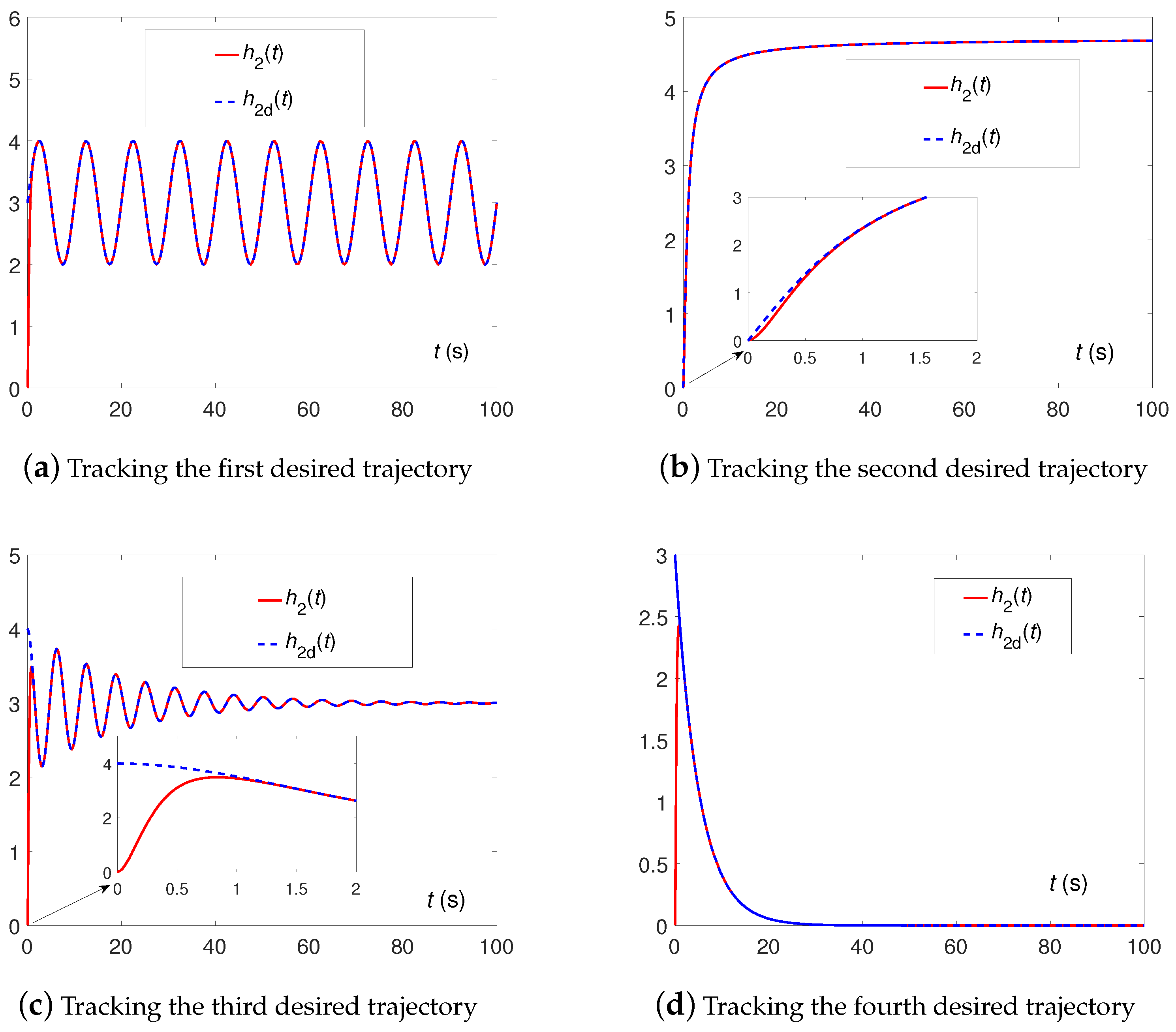
All above corresponding simulation results are displayed in Figure 3, Figure 4, Figure 5 and Figure 6. Specifically, Figure 3 shows the output liquid level h 2 ( t ) of the main tank T 2 under the four trajectories. From Figure 3a–d, we can observe that the actual output liquid level h 2 ( t ) of the main tank T 2 tracked the desired liquid level h 2 d ( t ) within a short time for all four different situations.
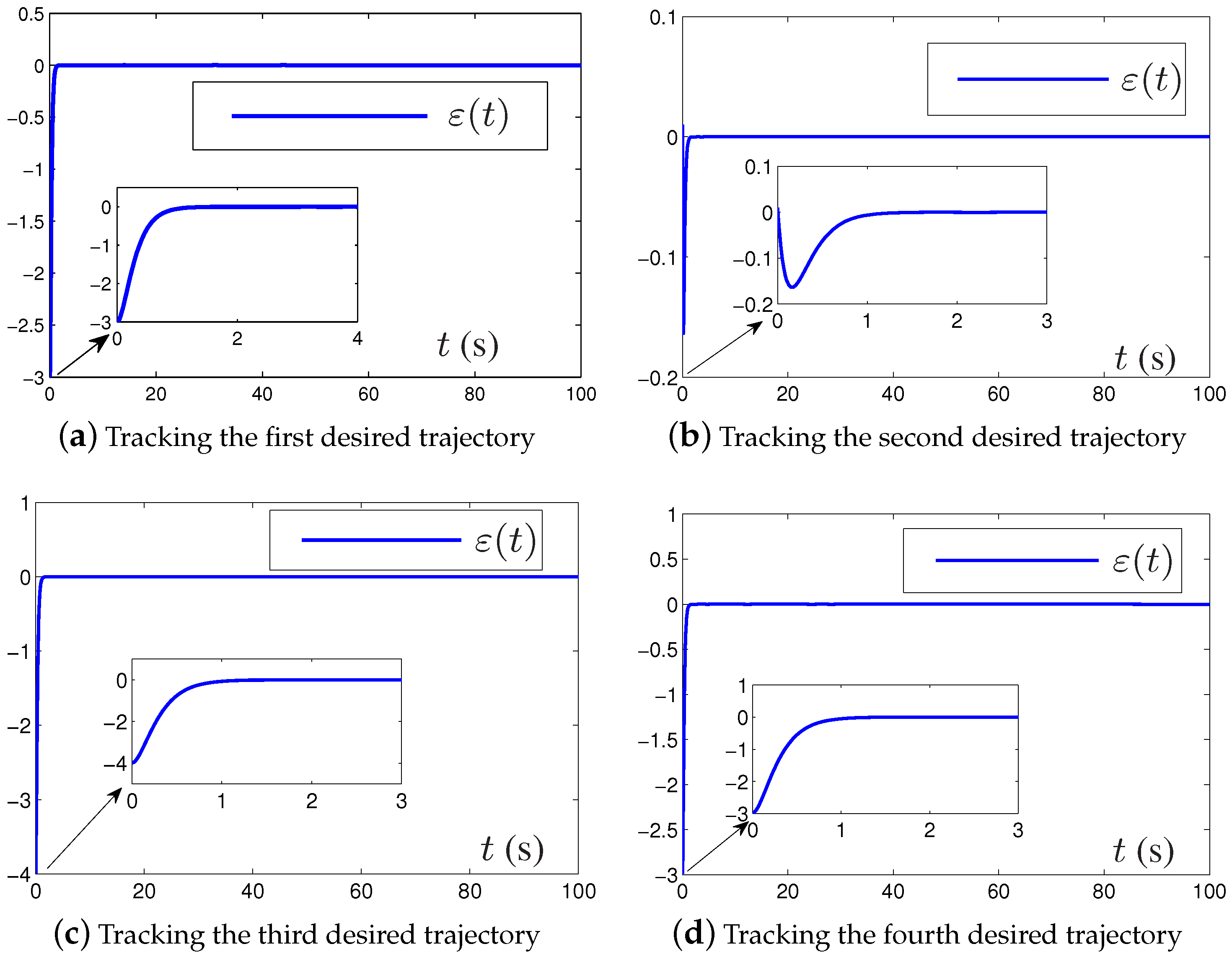
Figure 4 shows the tracking errors between the output liquid level h 2 ( t ) of the main tank T 2 and the desired liquid level h 2 d ( t ) under the four trajectories. From Figure 4a–d, we can observe that the tracking errors ε ( t ) of the main tank T 2 exponentially converged to zero within a short time for all four different situations.
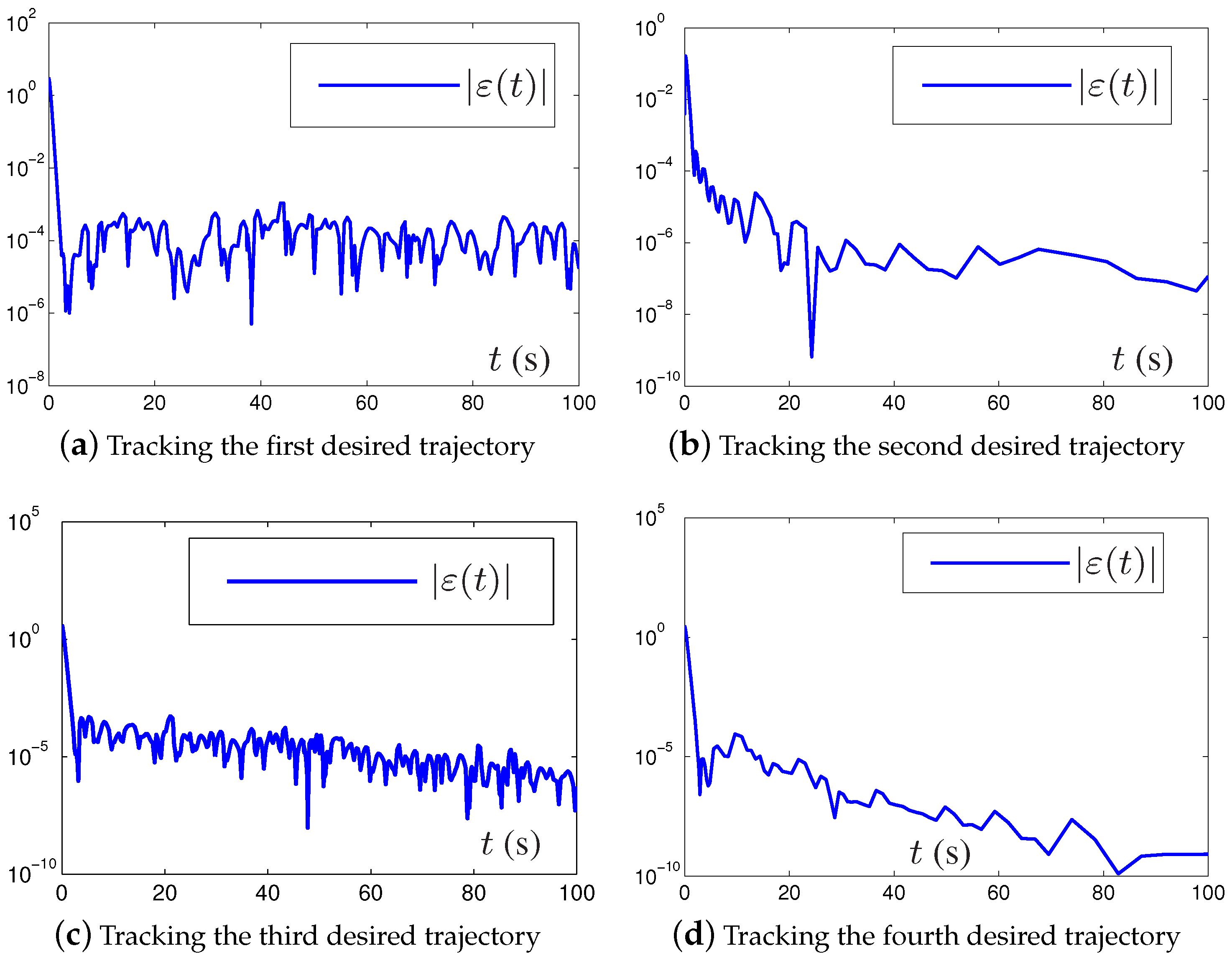
Figure 5 shows the absolute tracking error (in log scale) between the output liquid level h 2 ( t ) of the main tank T 2 and the desired liquid level h 2 d ( t ) under the four trajectories. From Figure 5a–d, we can observe that the steady-state absolute tracking errors (in log scale), termed | ε ( t ) | , for the main tank T 2 presented low orders for all four different situations.
Figure 6 shows the main-control valve opening, termed u ( t ) , under the four situations. For the first situation, starting from appropriate initial state, the liquid level h 2 ( t ) of the main tank T 2 oscillated periodically with a regular frequency. Simultaneously, the main-control valve opening u ( t ) (i.e., the control signal) also oscillated periodically with a regular frequency. For the second situation, starting from appropriate initial state, the liquid level h 2 ( t ) of the main tank T 2 monotonically increased and finally maintained a stable value. Simultaneously, the main-control valve opening u ( t ) increased and finally maintained a stable value, as similarly observed in the third situation. For the fourth situation, starting from an appropriate initial state, the liquid level h 2 ( t ) of the main tank T 2 monotonically decreased and gradually converged to zero, which coincides with the industrial situation of draining the non-linear double-holding water tank system. Similarly, the main-control valve opening u ( t ) decreased and gradually converged to zero. From Figure 6a–d, we can observe that the main-control valve opening u ( t ) remained smooth under the four different situations, which is suitable for engineering applications.
All of the above simulation results coincided well with the convergence analysis in Theorem 1. Moreover, these simulation results also validated the effectiveness of the ZD controller (13) with respect to the double-holding water tank system (7).

5.2. Examples for Robustness Investigation

In this subsection, we investigate the double-holding water tank system controlled by the ZD controller. Furthermore, a simulation example is presented, through which we verify the robustness of the double-holding water tank in the presence of time-varying bounded perturbations.
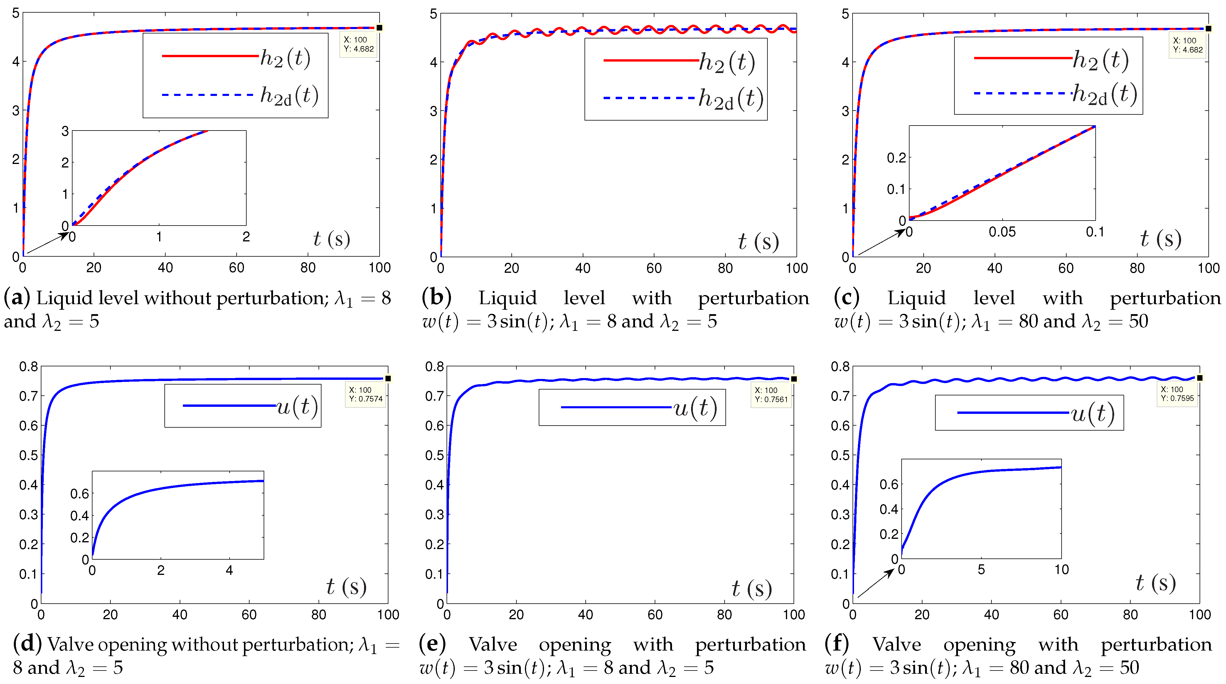
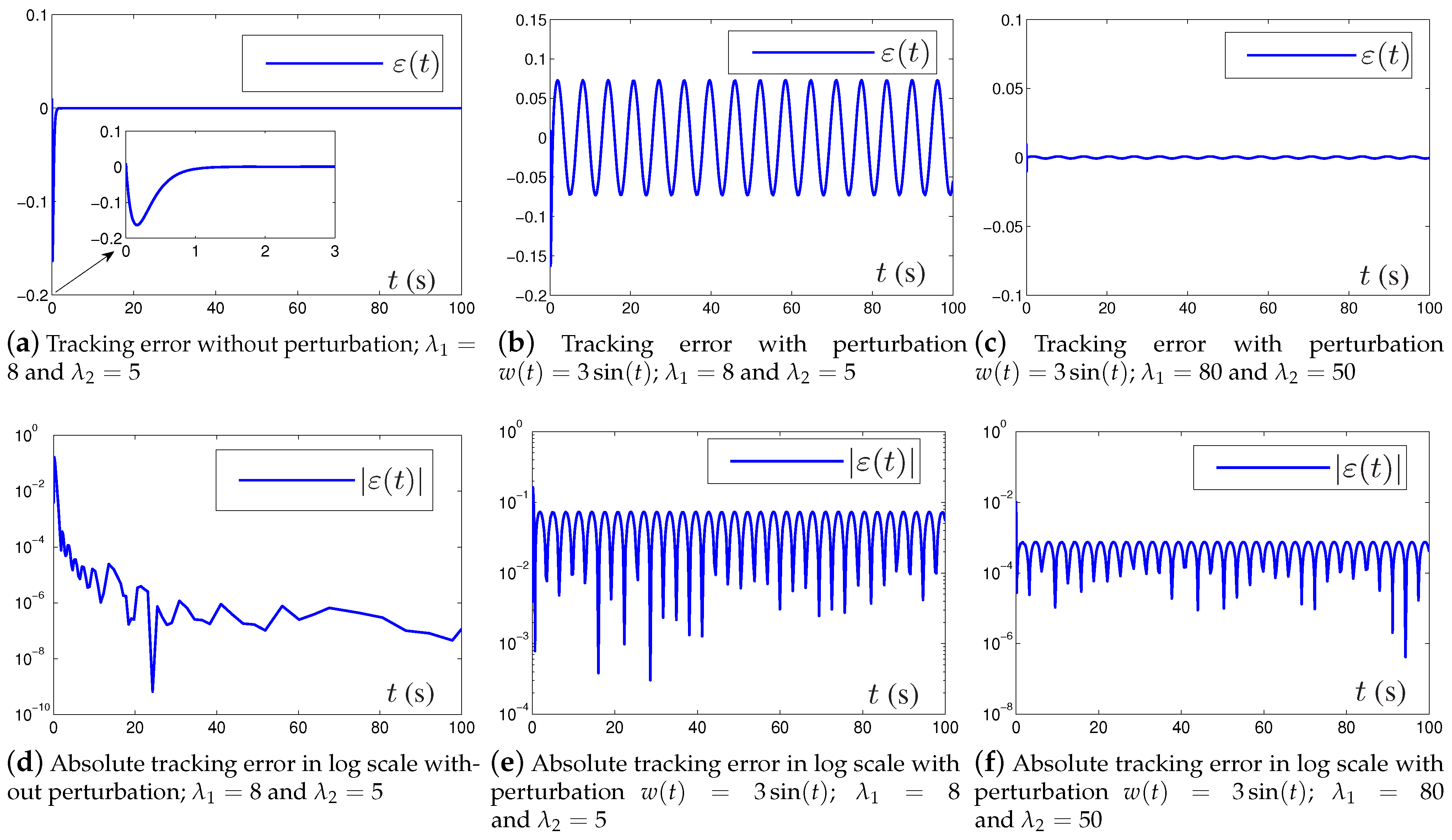
Moreover, the second situation is studied, which starts from the appropriate initial state h 2 ( 0 ) = 0.01 ,   h ˙ 2 ( 0 ) = 0 . The corresponding desired trajectory is h 2 d ( t ) = 3 arctan ( t ) . Consider the double-holding water tank system with time-varying bounded perturbation w ( t ) = 3 sin ( t ) in (16). The profiles for the liquid level and valve opening of the double-holding water tank system with and without the time-varying bounded perturbation are displayed in Figure 7, while the tracking errors of the double-holding water tank system with and without the time-varying bounded perturbation are displayed in Figure 8.
For comparison, Figure 7a,d show the liquid level and valve opening results for the double-holding water tank system without perturbation, while Figure 7b,e show the those for the double-holding water tank system with constant perturbation w ( t ) = 3 sin ( t ) . Note that, in both cases, the associated design parameters are set as λ 1 = 8 and λ 2 = 5 . From Figure 7b, it can be seen that when the double-holding water tank system is subject to the time-varying bounded perturbation w ( t ) = 3 sin ( t ) , the actual output liquid level h 2 ( t ) of the main tank T 2 cannot track the desired trajectory h d ( t ) very well and oscillates continuously, compared with that shown in Figure 7a; similar results can be observed for the valve opening u ( t ) of the double-holding water tank system. To achieve better tracking performance and restrain the oscillation, the associated design parameters λ 1 and λ 2 were increased to 80 and 50. The corresponding simulation results are shown in Figure 7c,f, from which we can see that the actual output liquid level h 2 ( t ) of the main tank T 2 tracked the desired trajectory h d ( t ) very well, without oscillation.
The corresponding tracking errors are shown in Figure 8. It can be seen, from Figure 8a,d, that starting with given initial states without perturbation, the tracking error ε ( t ) of the main tank T 2 exponentially converged to zero within a short time, and the steady-state absolute tracking error | ε ( t ) | (in log scale) of the main tank T 2 converged to an error bound and remained on the order of 10 6 . From Figure 8b,e, it can be seen that, when the double-holding water tank system was subject to the time-varying bounded perturbation w ( t ) = 3 sin ( t ) , the tracking error ε ( t ) oscillated within the range of 0.1 to 0.1 , and the steady-state absolute tracking error | ε ( t ) | converged to an error bound and remained on the order of 10 2 10 1 . To achieve better tracking performance and restrain the oscillation, the associated design parameters λ 1 and λ 2 were increased to 80 and 50, respectively. The corresponding simulation results are shown in Figure 8c,f, from which we can see that ε ( t ) approximately converged to zero quickly, while | ε ( t ) | converged to an error bound and remained on the order of 10 3 10 4 .
From Figure 7 and Figure 8, we can draw the conclusion that when the double-holding water tank system is subject to the time-varying bounded perturbation w ( t ) = 3 sin ( t ) , the steady-state tracking error becomes larger and oscillates, which can be restrained by adjusting the design parameters λ 1 and λ 2 . This coincided well with the convergence analysis, from which it was found that the associated steady-state tracking errors can be made arbitrarily small by increasing λ 1 and λ 2 to be sufficiently large (see Theorem 2).

5.3. Comparison

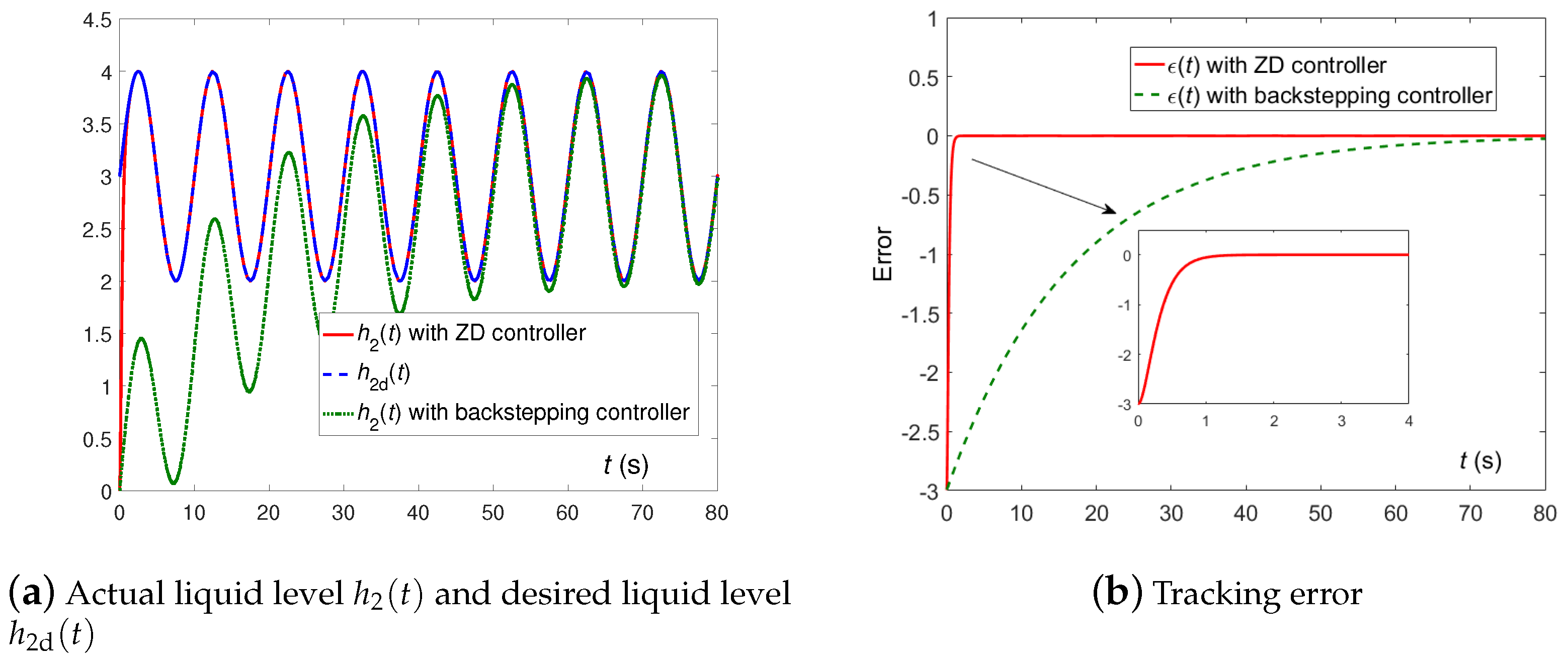
It is well-known that traditional PID [2,4] controllers are some of the most commonly used controllers in practical applications. However, traditional PID is mainly designed for linear systems. In terms of non-linear and time-varying systems, the PID controller may not provide precise tracking control, and the performance of the PID controller will deteriorate in the presence of perturbations or noises. Backstepping control [20,21,22,23] is used to design controllers for non-linear systems, especially for high-order systems. This method decomposes the non-linear system into multiple sub-systems and designs a controller for each sub-system sequentially, thereby designing a controller for the entire system. Thus, backstepping control consists of multiple virtual controllers comprising the actual controller. However, as the order of the system increases, the controller design becomes more difficult and complicated. In this paper, for comparison, the tracking control of the double-holding water tank equipped with a backstepping controller is conducted, in order to further illustrate the performance of the ZD method. The corresponding simulation results are shown in Figure 9. All of the system parameters are as in Section 5.1. Figure 9a,b show that the ZD controller presented a faster tracking speed and better tracking performance.

6. Conclusions

Tracking control of a double-holding water tank system through the use of a proposed ZD controller was investigated in this paper. First, a non-linear model of the double-holding water tank system was constructed. For better tracking performance, the ZD method was used several times to design the ZD controller. Moreover, the robustness of the double-holding water tank system controlled by the ZD controller was further investigated, and corresponding theoretical analyses were conducted to validate the convergence performance of the ZD controller. In addition, simulation experiments considering four different tracking trajectories corresponding to four different practical situations were conducted. Furthermore, extra simulation experiments considering time-varying perturbations and a comparative simulation based on the backstepping method were also conducted. All of these simulation results successfully illustrated the feasibility and effectiveness of the ZD method for tracking control of the double-holding water tank system. Practical systems are typically characterized by many uncertainties, such as unknown control direction and input–output coupling, and we intend to study and address these problems in the future work.

Author Contributions

Conceptualization, Y.Z.; methodology, Y.D., B.Q. and Y.Z.; software, Y.D. and H.J.; validation, Y.D. and B.Q.; formal analysis, Y.D. and H.J.; investigation, Y.D. and B.Q.; resources, Y.D. and Y.Z.; data curation, Y.D.; writing—original draft preparation, Y.D.; visualization, Y.D. and H.J.; supervision, B.Q., Y.Z. and H.J.; project administration, Y.Z. and B.Q.; funding acquisition, Y.Z. and B.Q. All authors have read and agreed to the published version of the manuscript.

Funding

The work is supported by the National Natural Science Foundation of China (with numbers 62006254 and 61976230), the Project Supported by Guangdong Province Universities and Colleges Pearl River Scholar Funded Scheme (with number 2018), the Shenzhen Outbound Postdoctoral Program (with number SZBH202127), the Key-Area Research and Development Program of Guangzhou (with number 202007030004), the Guangdong Basic and Applied Basic Research Foundation (with number 2020A1515110958), and also the Research Fund Program of Guangdong Key Laboratory of Modern Control Technology (with number 2017B030314165).

Data Availability Statement

Not applicable.

Conflicts of Interest

The authors declare no conflict of interest.

References

  1. Zhang, H.Y.; Zhang, L.X. The simulation on double tank water level control based Matlab. Appl. Mech. Mater. 2012, 217, 1435–1439. [Google Scholar] [CrossRef]
  2. Yu, M.; Jia, H.L.; Chen, P.J. The research on the system of double-holding water tank liquid level control with the PID control. Adv. Mater. Res. 2014, 945, 2559–2562. [Google Scholar] [CrossRef]
  3. Auroux, D.; Bonnabel, S. Symmetry-preserving observers for some water tank problems: Theory and application to a shallow water model. Mathematics 2008, 67, 1122. [Google Scholar]
  4. Lin, Y.; Ye, X.L. Cascade fuzzy self-tuning PID control for the liquid-level control of double water-tank. Adv. Mater. Res. 2011, 383, 207–212. [Google Scholar] [CrossRef]
  5. Zhou, K.; Yan, B.; Jiang, Y.; Huang, J. Double-tank liquid level control based on genetic algorithm. In Proceedings of the 4nd IEEE International Conference on Intelligent Human-Machine Systems and Cybernetics, Nanchang, China, 26–27 August 2012; pp. 354–357. [Google Scholar]
  6. Hu, L.; Li, G.; Huang, W. Level control system of double-hold water tank based on inverse system method and PID. In Proceedings of the 2nd IEEE International Conference on Intelligent Human-Machine Systems and Cybernetics, Nanjing, China, 26–28 August 2010; pp. 129–132. [Google Scholar]
  7. Zhang, R.; Cao, Z.; Lu, R.; Li, P.; Gao, F. State-space predictive-P control for liquid level in an industrial coke fractionation tower. IEEE Trans. Autom. Sci. Eng. 2015, 12, 1516–1524. [Google Scholar] [CrossRef]
  8. Zhang, Y.; Ding, Y.-Q.; Qiu, B.; Wen, J.; Li, X.-D. ZD method based nonlinear and robust control of agitator tank. Asia J. Contr. 2018, 20, 1464–1479. [Google Scholar] [CrossRef]
  9. Yang, L.; Zhao, L.; Chen, X.; Zhang, Z.; Nian, H.; Zhao, J.; Deng, R.; Yan, L. Robust active damping control for LCL-type shunt active power filters. IEEE Access 2022, 10, 39456–39470. [Google Scholar] [CrossRef]
  10. Gillis, N. Robustness analysis of hottopixx, a linear programming model for factoring nonnegative matrices. Mathematics 2012, 34, 1189–1212. [Google Scholar] [CrossRef] [Green Version]
  11. Bououden, S.; Chadli, M.; Karimi, H.R. A robust predictive control design for nonlinear active suspension systems. Asia J. Contr. 2016, 18, 122–132. [Google Scholar] [CrossRef]
  12. Jin, L.; Li, S.; Hu, B.; Liu, M.; Yu, J. A noise-suppressing neural algorithm for solving the time-varying system of linear equations:A control-based approach. IEEE Trans. Ind. Inform. 2019, 15, 236–246. [Google Scholar] [CrossRef]
  13. Sun, Z.; Li, F.; Zhang, B. Different modified zeroing neural dynamics with inherent tolerance to noises for time-varying reciprocal problems: A control-theoretic approach. Neurocomputing 2019, 337, 165–179. [Google Scholar] [CrossRef]
  14. Zhang, Z.; Chen, T.; Wang, M.; Zheng, L. An exponential-type anti-noise varying-gain network for solving disturbed time-varying inversion systems. IEEE Trans. Neural Netw. Learn. Syst. 2021, 31, 3414–3427. [Google Scholar] [CrossRef]
  15. Li, W.; Xiao, L.; Liao, B. A finite-time convergent and noise rejection recurrent neural network and its discretization for dynamic nonlinear equations solving. IEEE Trans. Cybern. 2020, 50, 3195–3207. [Google Scholar] [CrossRef]
  16. Yin, C.; Zhao, D.; Zhang, J.; Wang, S.; Xu, X.; Sun, X.; Shi, D. Body height robust control of automotive air suspension system using finite time approach. Asia J. Contr. 2021, 24, 859–871. [Google Scholar] [CrossRef]
  17. Ding, Y.-Q.; Li, X.-D. A unified adaptive control approach of nonlinear continuous non-parameterized systems with asymmetric control gain for trajectory tracking in different domains. Int. J. Robust Nonlinear Control 2023, 33, 3964–3987. [Google Scholar] [CrossRef]
  18. Yue, D.; Cao, J.; Li, Q.; Liu, Q. Neural-network-based fully distributed adaptive consensus for a class of uncertain multiagent systems. IEEE Trans. Neural Netw. Learn. Syst. 2021, 32, 2965–2977. [Google Scholar] [CrossRef]
  19. Yu, J.; Dong, X.; Li, Q.; Lü, J.; Ren, Z. Fully adaptive practical time-varying output formation tracking for high-order nonlinear stochastic multiagent system with multiple leaders. IEEE Trans. Cybern. 2021, 51, 2265–2277. [Google Scholar] [CrossRef]
  20. Xu, Q.-Y.; Li, X.-D. HONN-based adaptive ILC for pure-feedback non-affine discrete-time systems with unknown control direction. IEEE Trans. Neural Netw. Learn. Syst. 2020, 31, 212–224. [Google Scholar] [CrossRef] [PubMed]
  21. Chen, Q.; Shi, H.; Sun, M. Echo state network-based backstepping adaptive iterative learning control for strict-feedback systems: An error-tracking approach. IEEE Trans. Cybern. 2020, 50, 3009–3022. [Google Scholar] [CrossRef]
  22. Wang, H.; Liu, S.; Wang, D.; Niu, B.; Chen, M. Adaptive neural tracking control of high-order nonlinear systems with quantized input. Neurocomputing 2021, 456, 156–167. [Google Scholar] [CrossRef]
  23. Huang, H.; Shirkhani, M.; Tavoosi, J.; Mahmoud, O. A new intelligent dynamic control method for a class of stochastic nonlinear systems. Mathematics 2022, 10, 1406. [Google Scholar] [CrossRef]
  24. Zhang, H.; Li, B.; Xiao, B.; Yang, Y.; Ling, J. Nonsingular recursive-structure sliding mode control for high-order nonlinear systems and an application in a wheeled mobile robot. ISA Trans. 2022, 130, 553–564. [Google Scholar] [CrossRef]
  25. Zhang, J.; Meng, W.; Yin, Y.; Li, Z.; Ma, L.; Liang, W. High-order sliding mode control for three-joint rigid manipulators based on an improved particle swarm optimization neural network. Mathematics 2022, 10, 3418. [Google Scholar] [CrossRef]
  26. Antipov, A.; Krasnova, S.; Utkin, V. Methods of ensuring invariance with respect to external disturbances: Overview and new advances. Mathematics 2021, 9, 3140. [Google Scholar] [CrossRef]
  27. Drakunov, S.V.; Izosimov, D.B.; Luk’yanov, A.G.; Utkin, V.A. The block control principle I. Autom. Remote Control 1990, 51, 601–609. [Google Scholar]
  28. Zhang, Y.; Qiu, B.; Li, X.-D. Zhang-Gradient Control; Springer: Singapore, 2020. [Google Scholar]
  29. Li, J.; Mao, M.; Zhang, Y. Simpler ZD-achieving controller for chaotic systems synchronization with parameter perturbation, model uncertainty and external perturbation as compared with other controllers. Opt.-Int. J. Light Electron Opt. 2016, 131, 364–373. [Google Scholar] [CrossRef]
  30. Zhang, Y.; Zhang, Y.; Chen, D.; Xiao, Z.; Yan, X. From davidenko method to Zhang dynamics for nonlinear equation systems solving. IEEE Trans. Syst. Man Cybern. Syst. 2017, 47, 2817–2830. [Google Scholar] [CrossRef]
  31. Qiu, B.; Guo, J.; Li, X.; Zhang, Z.; Zhang, Y. Discrete-time advanced zeroing neurodynamic algorithm applied to future equality-constrained nonlinear optimization with various noises. IEEE Trans. Cybern. 2022, 52, 3539–3552. [Google Scholar] [CrossRef] [PubMed]
  32. Qiu, B.; Zhang, Y. Two new discrete-time neurodynamic algorithms applied to online future matrix inversion with nonsingular or sometimes-singular coefficient. IEEE Trans. Cybern. 2019, 49, 2032–2045. [Google Scholar] [CrossRef] [PubMed]
  33. Qiu, B.; Zhang, Y.; Yang, Z. New discrete-time ZNN models for least-squares solution of dynamic linear equation system with time-varying rank-deficient coefficient. IEEE Trans. Neural Netw. Learn. Syst. 2018, 29, 5767–5776. [Google Scholar] [CrossRef]
  34. Guo, P.; Zhang, Y. Tracking control for triple-integrator and quintuple-integrator systems with single input using zhang neural network with time delay caused by backward finite-divided difference formulas for multiple-order derivatives. Mathematics 2022, 10, 1440. [Google Scholar] [CrossRef]
  35. Liao, S.; Li, S.; Liu, J.; Huang, H.; Xiao, X. A zeroing neural dynamics based acceleration optimization approach for optimizers in deep neural networks. Neural Netw. 2022, 150, 440–461. [Google Scholar] [CrossRef] [PubMed]
  36. Halliday, D.; Resnick, R.; Wa, J. Fundamentals of Physics; Wiley: Hoboken, NJ, USA, 2005. [Google Scholar]
  37. Zhang, Z.; Zhang, Y. Design and experimentation of acceleration-level drift-free scheme aided by two recurrent neural networks. IET Control Theory Appl. 2013, 7, 25–42. [Google Scholar] [CrossRef]
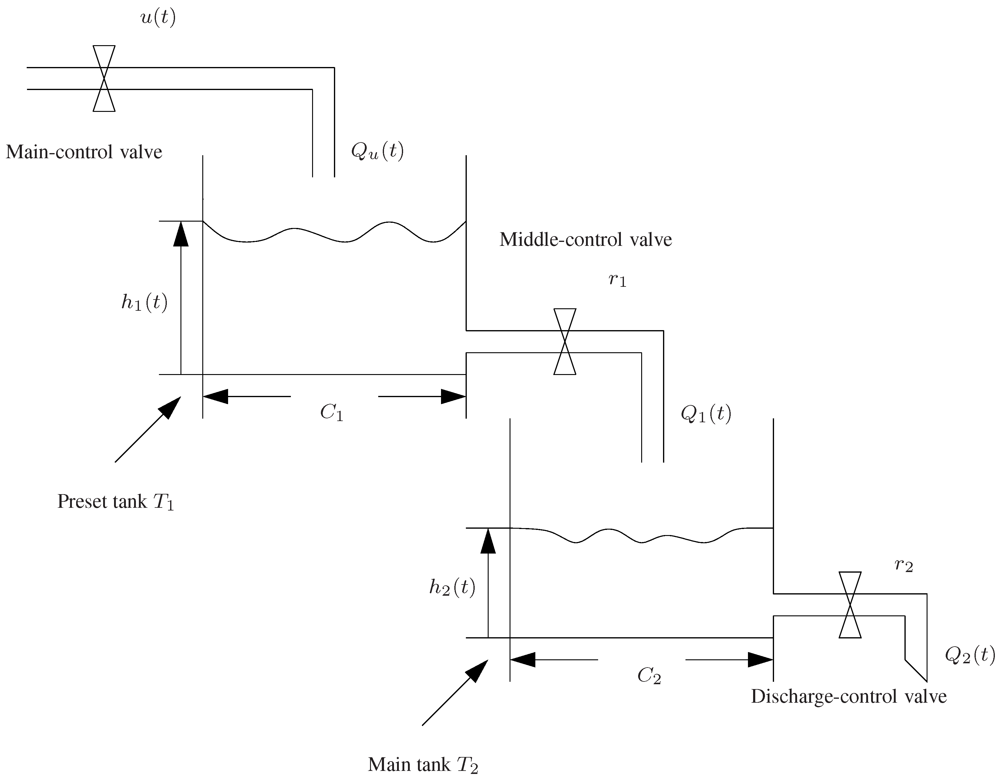
Figure 1. Fundamental structure of a double-holding water tank system.
Mathematics 11 02989 g001
Figure 2. Detailed realization of ZD method formulated in (12) for the double-holding water tank system.
Mathematics 11 02989 g002
Figure 3. Actual liquid level h 2 ( t ) and desired liquid level h 2 d ( t ) in four different situations with λ 1 = 8 and λ 2 = 5 .
Mathematics 11 02989 g003
Figure 4. Tracking errors in four different situations with λ 1 = 8 and λ 2 = 5 .
Mathematics 11 02989 g004
Figure 5. Absolute tracking errors (in log scale) in four different situations with λ 1 = 8 and λ 2 = 5 .
Mathematics 11 02989 g005
Figure 6. Main-control valve opening u ( t ) in four different situations with λ 1 = 8 and λ 2 = 5 .
Mathematics 11 02989 g006
Figure 7. Profiles for liquid level and valve opening of double-holding water tank system without or with time-varying bounded perturbation tracking the second desired trajectory.
Mathematics 11 02989 g007
Figure 8. Tracking errors of double-holding water tank system without or with time-varying perturbation tracking the second desired trajectory.
Mathematics 11 02989 g008
Figure 9. Liquid level tracking performance and error using ZD controller and backstepping controller.
Mathematics 11 02989 g009
Table 1. Different tracking trajectories for h d ( t ) and its derivatives.
Tracking Trajectory h 2 d ( t ) h ˙ 2 d ( t ) h ¨ 2 d ( t )
1 sin ( π t / 5 ) + 3 π cos ( π t / 5 ) / 5 π 2 sin ( π t / 5 ) / 25
2 3 arctan ( t ) 3 / ( 1 + t 2 ) 6 t / ( 1 + t 2 ) 2
3 cos ( t ) exp ( t / 20 ) + 3 sin ( t ) exp ( t / 20 ) 399 cos ( t ) exp ( t / 20 ) / 400
cos ( t ) exp ( 1 / 20 t ) / 20 + sin ( t ) exp ( t / 20 ) / 10
4 3 exp ( t / 5 ) 3 exp ( t / 5 ) / 5 3 exp ( t / 5 ) / 25
Disclaimer/Publisher’s Note: The statements, opinions and data contained in all publications are solely those of the individual author(s) and contributor(s) and not of MDPI and/or the editor(s). MDPI and/or the editor(s) disclaim responsibility for any injury to people or property resulting from any ideas, methods, instructions or products referred to in the content.