Article

Numerical Simulation of Mechanical Properties of Soil Considering the Effect of Internal Erosion

1
Nanchang Urban Planning & Design Institute Group Co., Ltd.; Nanchang 330038, China
2
School of Civil Engineering, Central South University, Changsha 410075, China
*
Author to whom correspondence should be addressed.
Mathematics 2023, 11(13), 2959; https://doi.org/10.3390/math11132959
Submission received: 6 June 2023 / Revised: 27 June 2023 / Accepted: 29 June 2023 / Published: 3 July 2023

Abstract

:
The loss of fine particles from the skeleton formed by coarse particles due to seepage action significantly affects the grading, void ratio, and mechanical properties of soil. This results in several issues of engineering hazards. In order to analyze the effect of internal erosion on the mechanical properties of gap-graded soils from macro and micro perspectives, triaxial consolidation and drainage shear tests were simulated in this paper using the particle flow discrete element software PFC3D. A linear contact model was employed to simulate internal erosion by randomly removing fine particles. The results showed that the void ratio of the specimens increased with the erosion degree. The variation in void ratios of the specimens with the erosion degree before loading was greater than those after loading. The peak deviatoric stresses of the specimens decreased with the increase of the erosion degrees. The larger the erosion degree, the more the maximum volumetric strain and the resistance capacity to deformation was also reduced. The average particle coordination number (Z) of the specimens generally tended to decrease as the erosion degree increased. When the average effective stress was not large, the critical state line gradually increased with the erosion degree, while the void ratio was also found to correlate with the erosion degree under the critical state of the specimens with zero average effective stress.

1. Introduction

Phenomena such as migration and loss of fine particles from soil voids formed by the soil skeleton due to seepage are described as internal erosion. Internal erosion significantly changes the properties and resulting behavior of soils. Different parameters, such as soil gradation, void ratio, and void structures, may change, consequently compromising the safety of engineering structures. It has been shown that a high proportion of failures in earth and rock dams have been attributed to internal erosion [1].
In recent years, internal erosion of soil has gained significant attention from the research community due to its hazardous effects. In order to investigate the effect of internal erosion on the mechanical properties of soil, many researchers have carried out a large number of theoretical and experimental studies. For example, Chang et al. [2] carried out a series of triaxial compression tests on internally unstable soils to explore the effects of internal erosion on stress-strain properties of soil. Ke and Takahashi [3,4] carried out seepage and drainage compression tests on saturated sandy soils with different initial fine particle contents under varying stress states to examine the permeability characteristics of internal erosion and its effect on the resulting mechanical properties of soil. Ouyang and Takahashi [5] studied the effect of initial fine particle content on the structural compositions of eroded soils and the mechanical behaviors of internally eroded soils by conducting seepage and undrained uniaxial compression tests. Yang et al. [6] simulated the internal erosion by dissolving pre-installed glucose columns in the specimens and performed triaxial compression tests on specimens with different initial densities and confining pressure. Chen et al. [7] studied the effect of internal erosion on stress-strain characteristics of soil through triaxial drainage shear tests using two groups of gap-graded sandy soils with different fine particle contents (i.e., 20% and 35%).
With the advancements in experimental and computational methods, many scholars have conducted in-depth investigations and validation studies on the internal erosion of soils through numerical simulations. Cai [8] used the coupling computational fluid dynamics and discrete element method (DEM) to conduct numerical simulations on the internal erosion process of the specimens with different particle gradations to explore the mechanism for seepage erosion of non-uniformly graded sandy soils. Scholtès et al. [9] utilized the open-source discrete element software Yade to propose a three-dimensional discrete element model and an analytical micromechanical model. They investigated the influence of removing particle components on the mechanical response of soils. The simulation results from both models exhibited a high degree of consistency, indicating a reduction in shear dilation of eroded soil after particle removal. Additionally, the authors pointed out that the soil void ratio, due to its well-defined physical meaning and ease of measurement, could serve as a model parameter to describe the impact of internal erosion phenomena on the mechanical behavior of soils. Zhang [10] adopted the 3D discrete element software PFC3D to numerically simulate the published experimental data where the built-in rotation-resistant linear contact model was utilized, and side walls were composed of 10 annular walls developed to simulate the flexible latex boundary in the tests. The numerical simulation and experimental results were consistent with each other in terms of the stress-strain behaviors of soil.
In this study, the three-dimensional particle flow discrete element software PFC3D was adopted for modeling the internal erosion of soils by randomly removing fine particles to investigate the effects of internal erosion and different erosion degrees on void ratio, stress-strain characteristics, resistance capacity to deformation, average particle coordination number, and the critical state line of gap-graded soils.

2. Research Significance

Compared with laboratory studies, numerical simulations have high operability and convenience in investigating fine structural changes and obtaining relevant fine mechanical parameters of the soils and rocks [11,12]. From the aforementioned research results, the hazards associated with internal erosion in soil include underground cavities caused by damage of deeply buried pipes, connected voids induced by the piping effect or soil flow, and local soil damage arising from microbial and other biochemical effects. The core problem of these hazards is the detachment and movement of soil particles, and this can be conveniently addressed through numerical simulation. Given the limitations of indoor experiments, this paper utilizes numerical simulation to comprehensively analyze the influence of internal erosion phenomena on various mechanical properties of soil by combining macroscopic and microscopic analyses. The patterns and conclusions obtained from this study can provide valuable references for practical engineering applications and future research.

3. Numerical Model

3.1. Overview of the PFC3D

Considering the complexity of geotechnical engineering issues, the particle flow method (PFC program), which is not restricted by the deformation amount, has been extensively employed in various practical engineering problems. It can study the mechanical problems of various discontinuous media and reflect the micro- and fine-scale mechanisms of granular materials under complex conditions.
For internal erosion tests, laboratory experiments are highly demanding regarding labor, test equipment, and test conditions. Often it is difficult to measure and control the specific amount of erosion, and the microstructure and mechanism cannot be further investigated. Therefore, numerical simulation tests for different scenarios can be conveniently implemented with the support of the PFC3D software. The PFC3D version 5.0 software was chosen for simulating internal erosion.

3.2. Assignment of Contact Model

Ten built-in contact models are provided in PFC3D version 5.0, including the linear model, linear contact adhesion model, parallel adhesion model, Hertzian contact model, hysteresis damping model, smooth joint model, flat seam joint model, roll-resistant linear contact model, Burgess creep model, and null model [13]. The linear contact model is one of the simplest and most operational models; the influence of different contact models on the experimental results is not the focus of this study; therefore, the linear contact model was chosen for this experiment. This model was developed from the linear model proposed by Cundall in 1979, as shown in Figure 1, where the contact force consists of two components, a linear component and a damped component. The two components are connected in parallel and act at an infinitely small interface. The linear component provides the linear elastic (tension-free) and frictional behavior, while the damped component offers the viscous behavior. This model does not resist relative rotation between the entities; thus, the contact moment is zero.
F c = F l + F d , M c 0
where Fl represents the linear force, and Fd represents the damping force.
The linear force is generated by a linear spring with constant normal and shear stiffness (kn, ks). Since the linear spring cannot maintain tension, the sliding condition is achieved by applying Coulomb’s criterion to the shear force through the friction coefficient μ. The damping force is generated by a viscous damper, and the viscosity is represented by the critical damping ratios in normal and shear directions (βn, βs).
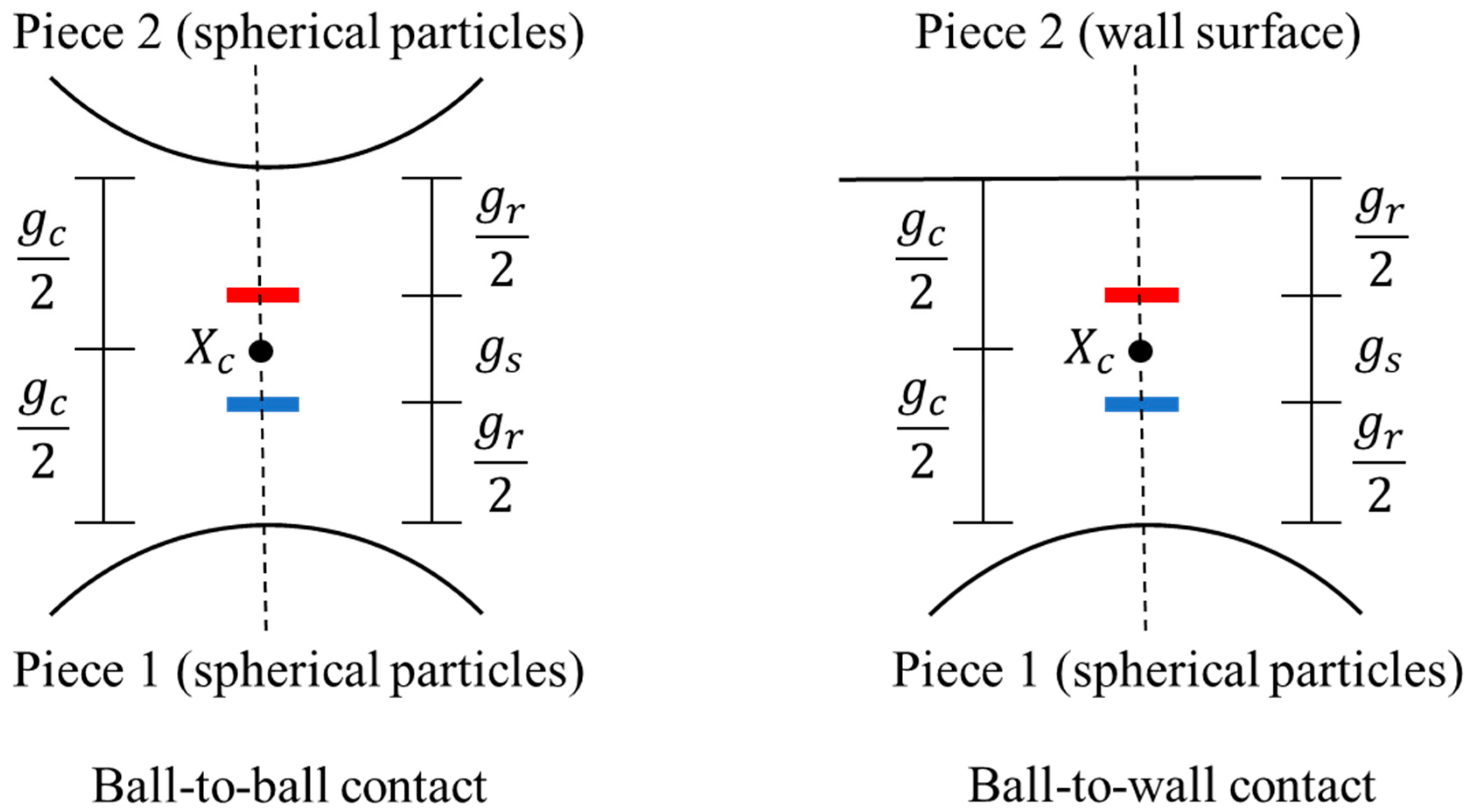
As shown in Figure 2, the particle surface gap, denoted as gs, can be defined as the difference between the contact gap, gc, and the reference gap, gr.
gs = gcgr
According to the given condition, the contact is considered activated and follows the force-displacement rule only when the particle surface gap, gs, is less than or equal to zero.
According to the force-displacement rule, both linear force and damping force can be decomposed into normal force and shear force components.
F l = F n l n ^ c + F s l , F d = F n d n ^ c + F s d
In this case, the linear normal force can be expressed as:
F n l = k n g s ,   g s < 0 0 ,   others ,   M l = 0 min F n l o + k n Δ δ n , 0 ,   M l = 1
where F n l o represents the linear normal force at the initial time step, and the linear normal force is only non-zero when the contact gap between particles is less than zero.
The linear shear force can be expressed as:
F s l = F s * , F s * F s μ F s μ F s * / F s * , others
where F s * represents the experimental shear force, and F s μ represents the shear strength. The shear strength can be calculated as follows:
F s μ = μ F n l
The damping normal force can be expressed as:
F n d = F * , M d = 0 , 2 min F * , F n l , M d = 1 , 3
where F * represents the load on the entire damper.
The damping shear force can be expressed as:
F s d = 2 β s m c k s δ ˙ s ,   no   sliding   or   M d = 0 , 2 0 ,   sliding   and   M d = 1 , 3
where mc can be expressed as:
m c = m 1 m 2 m 1 + m 2 m 1 , b a l l f a c e t , b a l l b a l l
where m(b) represents the mass of the entity (b), and δ ˙ s represents the relative shear translational velocity. When the linear shear force, F s l , is determined to be in a sliding state, F s d is equal to zero.

3.3. Numerical Modeling

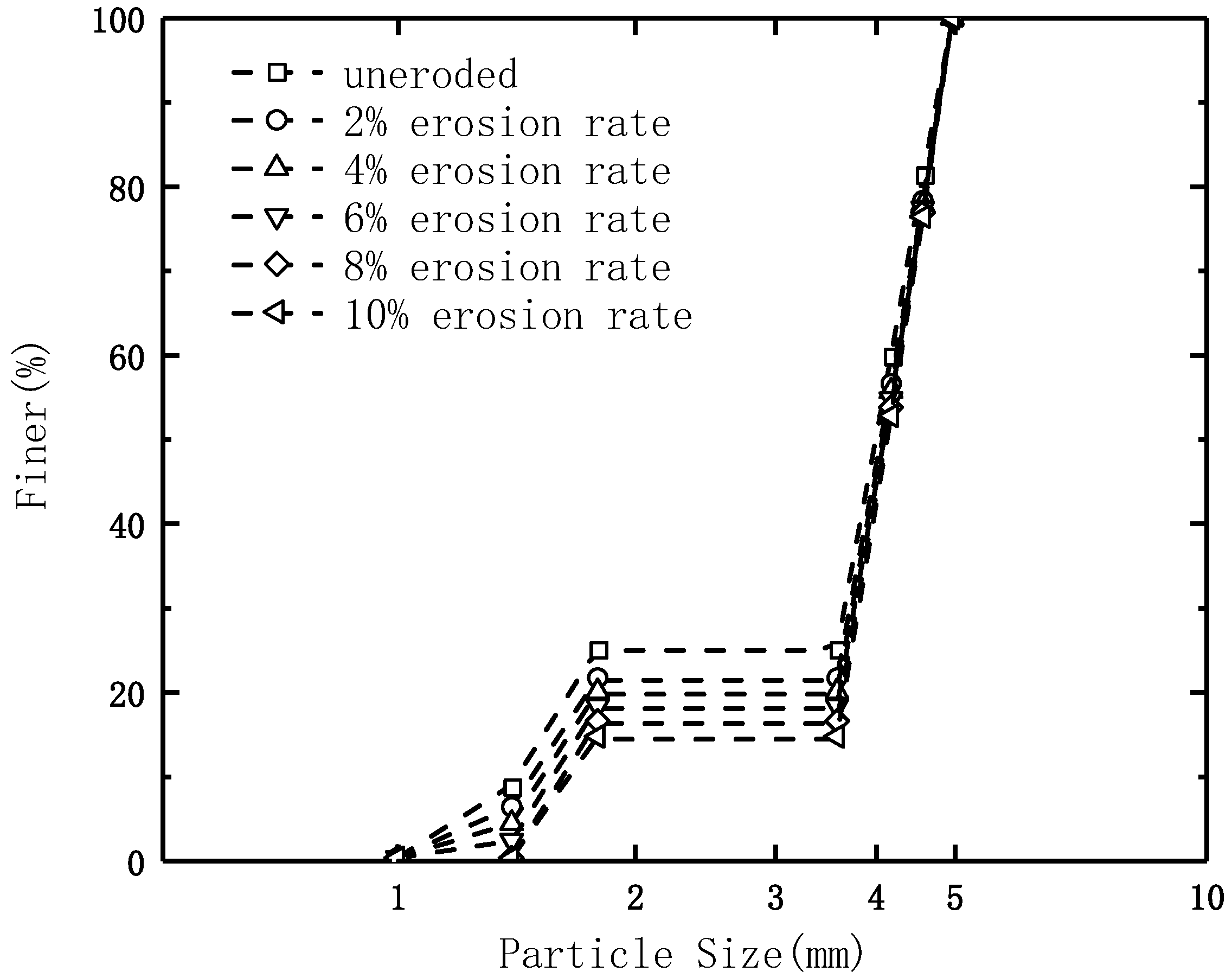
The PFC software was utilized to develop 40 mm diameter cylindrical specimens with 80 mm height. The particle size ranged from 1.0 mm to 5.0 mm. Because of computational efficiency constraints, the particle sizes were magnified by certain times with respect to the actual situation. Figure 3 shows the grading curves of the specimens. Particles of 1.0–1.8 mm and 3.6–5.0 mm were considered fine and coarse particles, respectively. The number of particles with 1.8–3.6 mm size was zero, so the soil was gap-graded.
Currently, many scholars are using salt particles as substitutes for erodible particles to simulate internal erosion under certain conditions. For instance, Chen et al. [7] utilized salt particles with fast dissolution rates and a size distribution that closely approximates uniformity to replace a specified quantity of fine particles within the soil. In their experiment, the soil sample was saturated with water containing carbon dioxide for two hours. Then, the saturated water was injected into the sample to fully dissolve the salt particles. After the dissolution process was completed, a triaxial compression test was conducted. This method of removing fine particles involves random deletion of their cores.
In this paper, the loss of particles was assumed to happen only due to the fine particles, and it was simulated by randomly removing particles when internal erosion occurred. The particles in the smallest size group and the size range of 1.0–1.4 mm were removed first while simulating particle removal. When all particles in the smallest group were removed, but the specimen did not achieve the required erosion degree, particles from the second smallest size group, i.e., the size range between 1.4 mm and 1.8 mm, were removed until the target erosion level was attained.
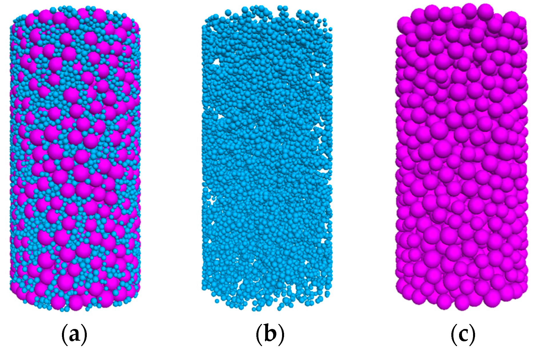
Figure 4 illustrates the model specimen with 12,165 particles, of which the fine and coarse particles were 10,810 and 1355, respectively. The microscopic parameters of the model specimen are listed in Table 1.

3.4. Numerical Simulations

Numerical simulations were carried out with the PFC, where the method of randomly removing particles was applied to simulate internal erosion. Five groups of specimens with different erosion degrees, i.e., 2%, 4%, 6%, 8%, and 10%, were prepared and tested together with uneroded specimens for triaxial consolidation and drainage shear under different effective confining pressures (the erosion degree mentioned here refers to the loss of fine particles corresponding to the mass fraction). The effective confining pressures were set as 100 kPa, 200 kPa, 400 kPa, and 800 kPa. A total of 24 groups of tests were conducted. Displacement-controlled loading was applied, and the tests were terminated when the axial shear strain reached 40%. The relevant test data, such as deviatoric stress-axial strain, volumetric strain-axial strain, average effective stress, and void ratio, were automatically recorded during the loading process.
Figure 5 illustrates the variations in gradation after the specimens were subjected to different erosion degrees. It can be seen that all particles in the smallest size group were removed upon reaching an erosion degree of 8%.

4. Results, Discussion, and Analysis

4.1. Analysis of Void Ratio Variation

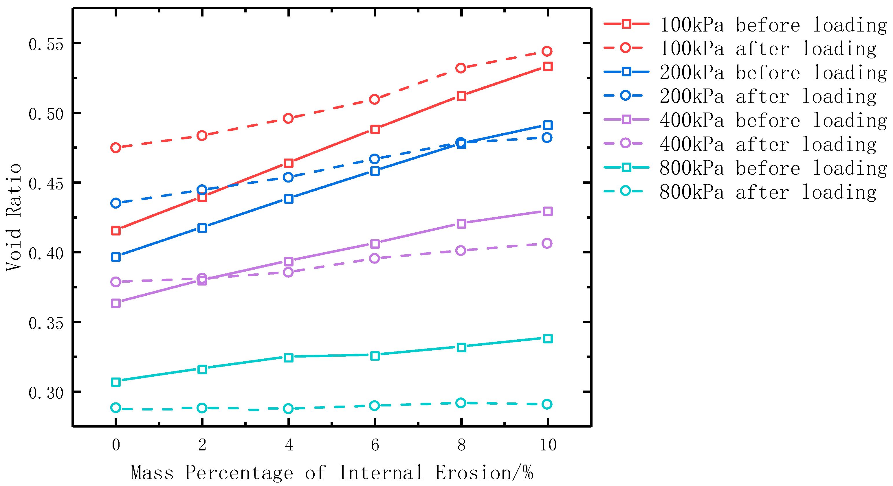
The void ratio is the ratio of the volume of voids to that of solid particles and reflects the looseness degree of the soil. The smaller the void ratio, the denser the soil and the lower the compressibility; the larger the void ratio, the looser the soil and the higher the compressibility. Figure 6 compares the void ratios of specimens with different erosion degrees under four confining pressure conditions before and after loading. It can be seen that, before and after loading, the higher the confining pressure, the smaller the void ratio, and the void ratio increased as the erosion degree increased. With the increasing confining pressure, the void ratio changed less with the erosion degree. At a confining pressure of 800 kPa, the void ratio of the soil after loading barely changed with the increasing erosion degree.
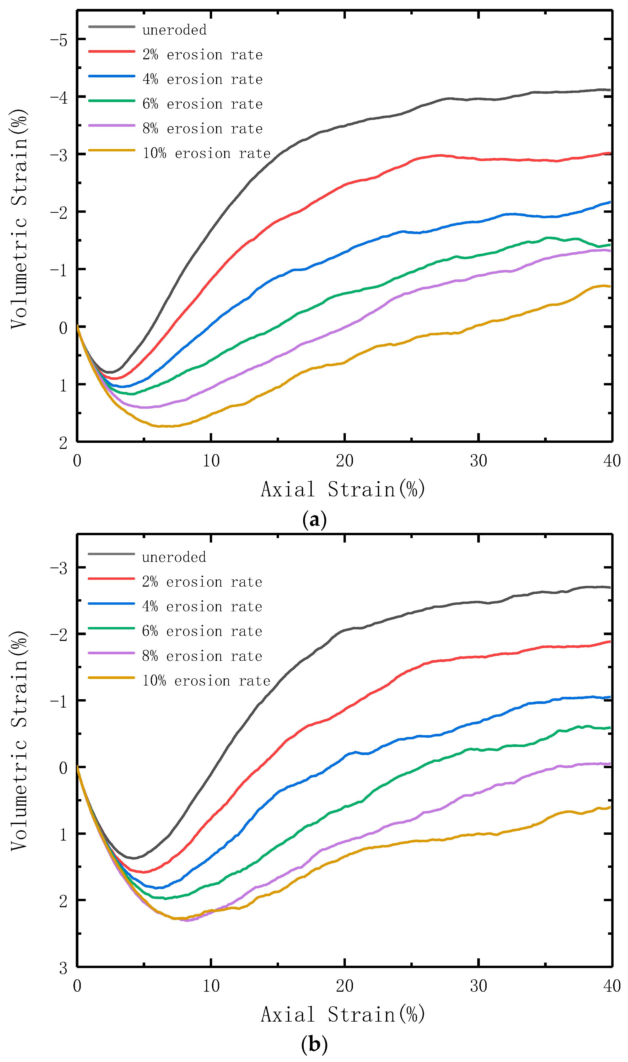
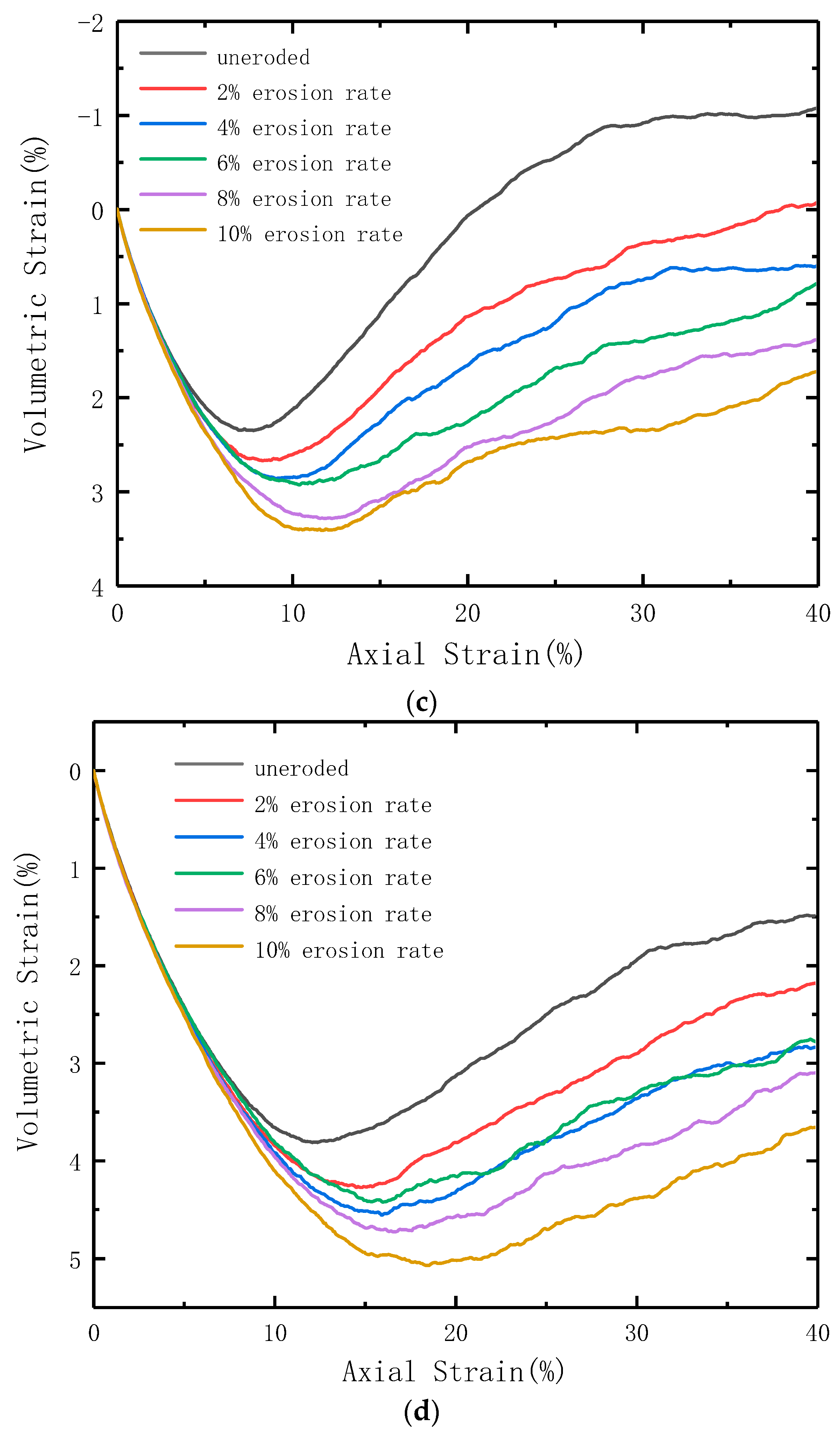
It can also be observed that the variation in void ratio before loading was more pronounced with the erosion degree than after loading, regardless of the confining pressure conditions. Under lower confining pressures, the void ratio after loading was greater than before loading. Nevertheless, the void ratio after loading progressively became smaller than that before loading as the confining pressure increased. From Figure 7 and Figure 8, it is concluded that this was due to the gradual change from shear expansion to shear contraction of the specimens as the confining pressure increased.

4.2. Analysis of Deviatoric Stress-Volumetric Strain-Axial Strain Curves

In order to compare the effects of different erosion degrees on variations of deviatoric stress and volumetric strain during specimen loading, the stress-strain curves and volumetric strain-axial strain curves of each group of specimens during loading are plotted here, followed by analysis.
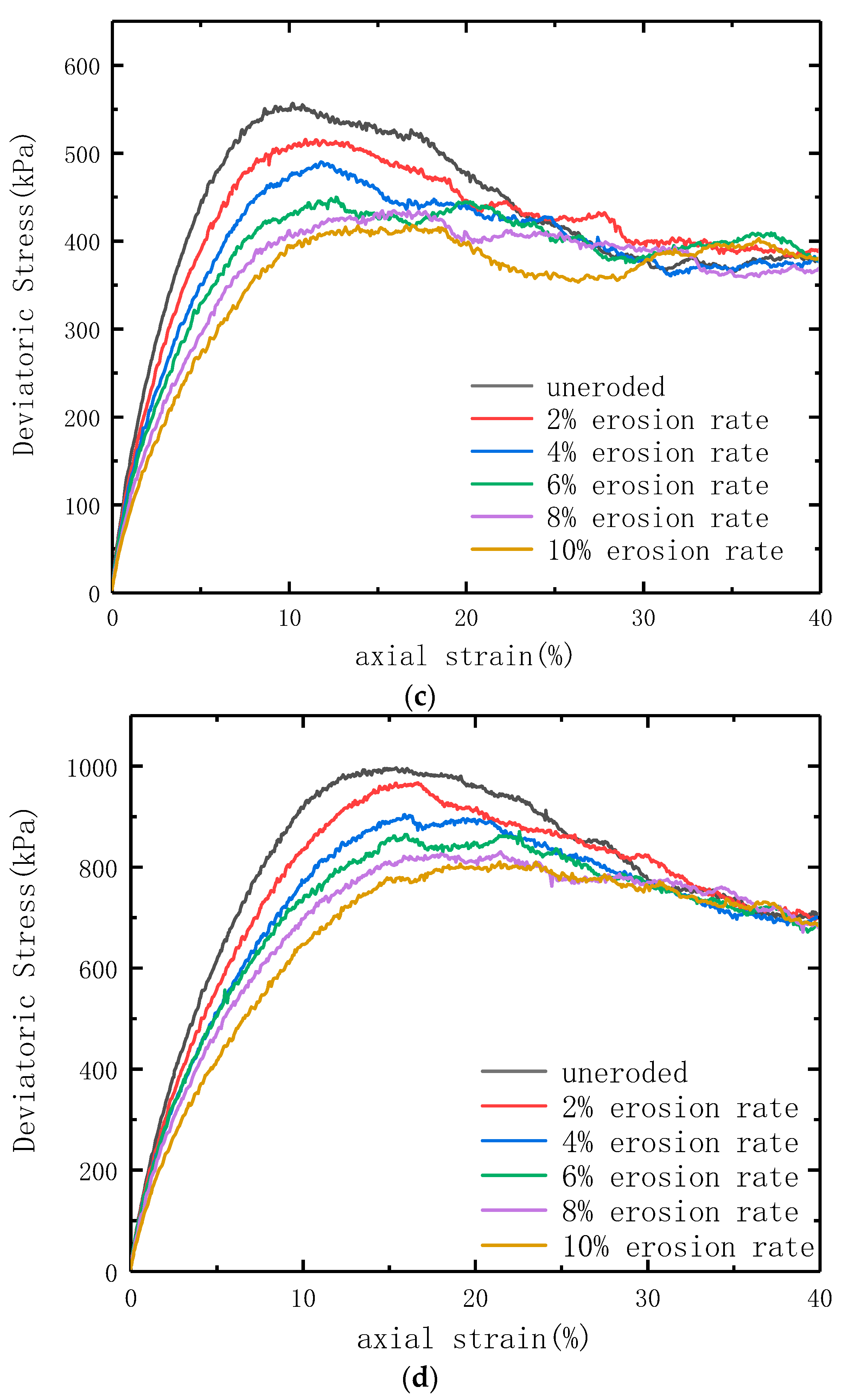
Figure 7 and Figure 8 show the comparison of deviatoric stress-axial strain curves and volumetric strain-axial strain curves for model specimens subjected to different internal erosion degrees when loaded to 40% axial strain at each effective confining pressure. Different colored curves represent different degrees of erosion in the figures. It is observed that the higher the effective confining pressure, the higher the peak deviatoric stress and the higher the maximum volumetric strain value of the specimens. However, the shear expansion property of the specimens at the later loading phase weakened. As the erosion degree increased, the peak deviatoric stress of the specimens decreased significantly and gradually transitioned from strain-softening to strain-hardening. The residual stress did not change much, the shear expansion property weakened, and specimens gradually changed from shear expansion to shear contraction. The greater the degree of erosion, the less resistance capacity the specimens have against deformation. It can be observed in Figure 7 that under the same confining pressure conditions, soil samples with different degrees of erosion exhibit nearly the same residual strength, which indicates that the influence of soil gradation changes caused by internal erosion on residual strength can be considered negligible. Such findings are similar to the experimental results on particle breakage of soils which indicate that the breakage-induced evolution of gradation shows a very limited influence on the residual strength of soils [14,15].

4.3. Variation in the Average Coordination Number of Particles

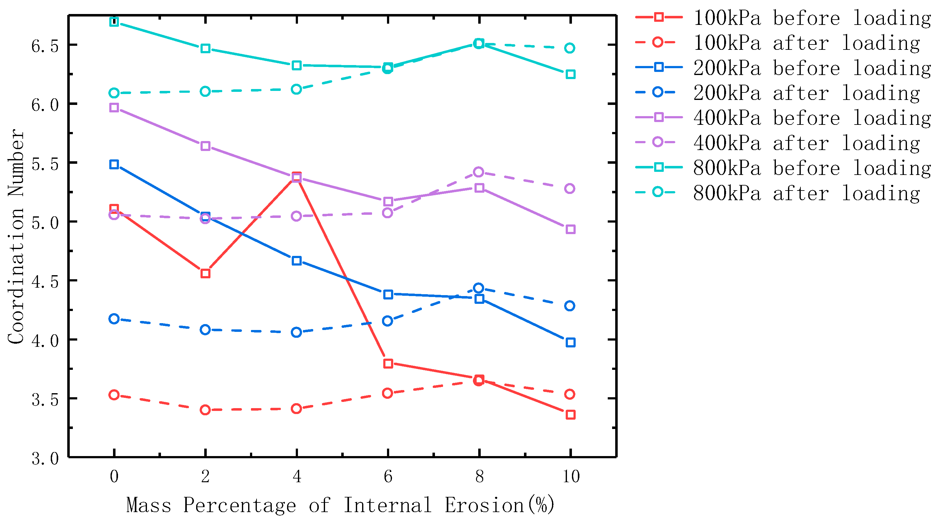
Figure 9 shows the comparison of the average particle coordination numbers (Z) of specimens with different erosion degrees before and after loading under different confining pressures. The average particle coordination number is a microscopic parameter describing the average number of contacts per particle [16]. At the microscale, the Z-value can reflect the compressive bearing capacity and deformability of the soil to some extent. The variation in the Z-value also indicates the degree of change in the internal structure of the soil under the influence of internal erosion. A smaller Z-value suggests a weaker compressive capacity and deformability of the soil specimen, while a larger Z-value indicates a larger impact of particle loss on the internal structure. The value of Z is calculated by Equation (10).
Z = 2 N c N P
where Z is the average coordination number of particles, Nc is the total number of contacts in the specimen, and Np is the total number of particles in the specimen.
As seen from Figure 9, the Z value generally decreased with the increasing erosion degree, both before and after loading, indicating that the specimen became looser and less resistant to compression and deformation as the degree of erosion increased. The Z value decreased or even increased for the degree of erosion varying from 6% to 8%. However, when the degree of erosion was between 8% and 10%, the Z value decreased again, demonstrating that more suspended particles with no contact force were lost when the degree of erosion reached 8%. For the same reason, it can be observed that under a confining pressure of 100 kPa, the pre-loading curve of the samples exhibits a significant increase at a 4% degree of erosion compared to a 2% degree of erosion. This is due to the fact that this study simulates internal erosion by randomly removing particles, and in this step, a large proportion of suspended particles are removed, resulting in a noticeable increase in the average particle coordination number. It can also be found that when the degree of erosion was small, the Z value before loading was much larger than after loading. As the erosion degree increased, the Z value before loading was smaller than that after loading because the greater the degree of erosion, the weaker the shear expansion of the specimens after loading.

4.4. Analysis of Critical State Lines

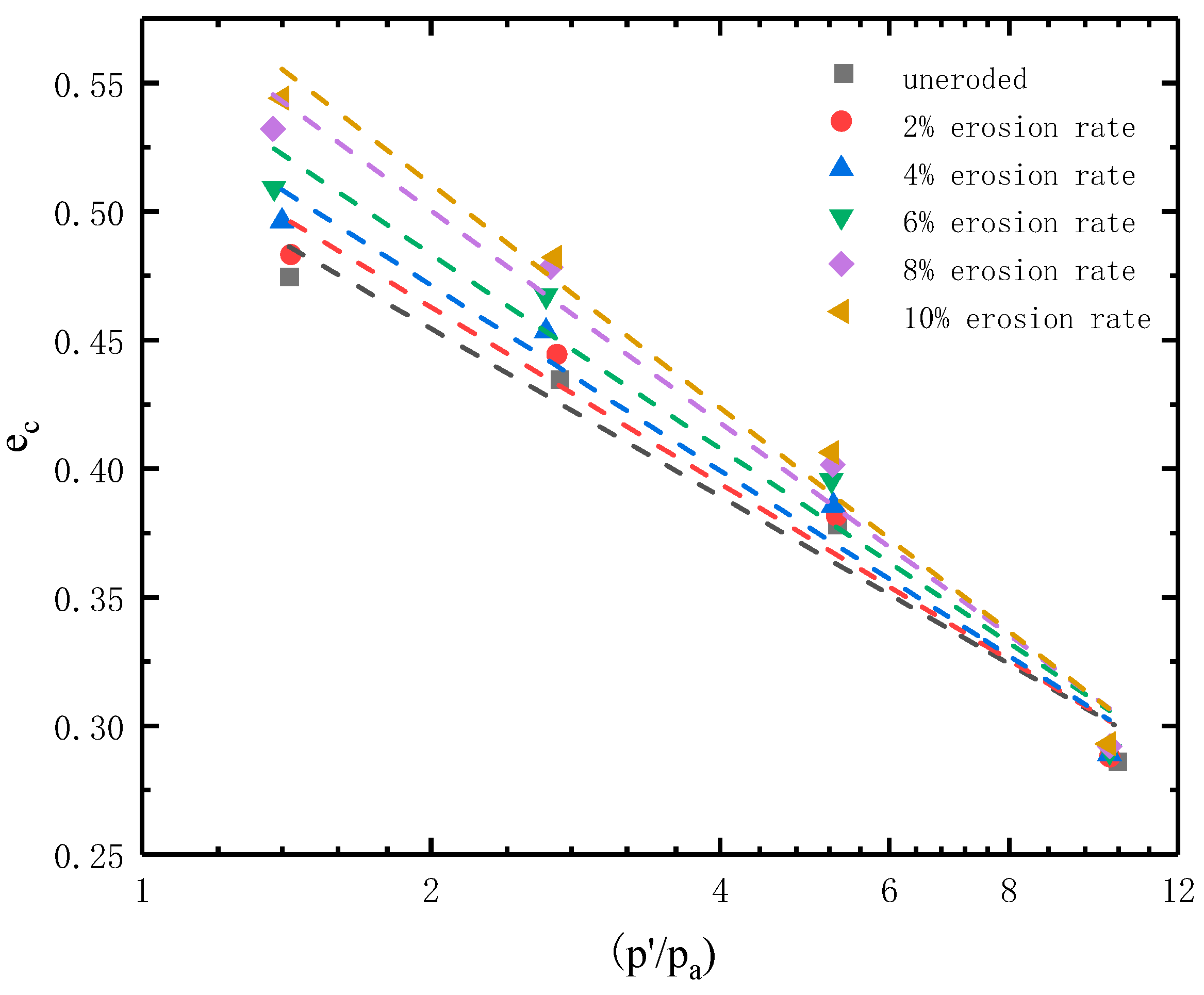
In order to analyze the critical state lines of the specimens, the critical state equation given in Equation (11) was adopted [17]. The critical state line can be fitted as a straight line in space e ln ( p / p a ) .
e c = e τ λ c ln ( p / p a )
where e c is the critical state porosity ratio, e τ is the critical state porosity ratio at p = 0 , λ c is the slope of the critical state line, p is the average effective stress, and p a is a standard atmospheric pressure, usually taken as 101.325 kPa.
By substituting the test data of the model specimens into Equation (11), the critical state void ratios and average effective stresses of the specimens at various erosion degrees under each confining pressure were plotted in the e ln ( p / p a ) plane and are shown in Figure 10. The parameters of the critical state lines were collated to yield Table 2, where R 2 is the coefficient of determination of the fitted straight line; the larger the R 2 value, the better the curve fitting.
It can be observed that the critical state line of the specimen can be fitted as a straight line under the same erosion state, which was as per Equation (11). For low average effective stresses, the critical state line gradually increased as the degree of erosion increased. In addition, as can be seen from Table 2, the intercepts of the fitted straight lines on the Y-axis were not equal for specimens with different degrees of erosion. This indicates that the void ratio in the critical state e τ at p = 0 was correlated with the erosion degree. As the degree of erosion increased, the absolute value λ c for the slope of the fitted straight line also increased, but there was no significant difference in the fitting effect of the straight line. The fitting was slightly worse for higher erosion degrees.

5. Limitations of the Study and Future Study Plans

The numerical simulation experiments conducted in this study employed a linear contact model, which is idealized and has certain limitations. In future studies, other contact models, such as the rolling resistance linear model, will be considered for experimentation. Additionally, the method used to simulate internal erosion involved randomly deleting fine particles from the specimens, which will be further explored to incorporate particle removal methods that better resemble real scenarios. Furthermore, this study only utilized one particle size distribution for the simulated experiments. In future work, a wider range of soil specimens with different particle size distributions will be included for simulation.

6. Conclusions

In this work, numerical simulations were conducted with the particle flow discrete element software PFC3D. The simulation method of randomly removing particles was used to prepare specimens with erosion degrees of 2%, 4%, 6%, 8%, and 10%. Together with the non-eroded specimens, the consolidation and drainage tests under different confining pressure conditions were performed to investigate the effects of internal erosion and different erosion degrees on the void ratio, strength, deformation, microscopic particle contact number, and the critical state line of the soil.
The conclusions obtained from the tests are summarized as follows.
  • Whether before or after loading, the void ratio of the specimens decreased as the confining pressure increased, while it increased with the increasing erosion degree. The higher the confining pressure, the smaller the variation of the void ratio with the degree of erosion. The variation of the void ratio with the degree of erosion was greater before loading than after loading. The void ratio after loading was greater than before loading when the confining pressure was small, and the opposite findings were found when the confining pressure was large.
  • As the degree of erosion increased, the peak deviatoric stress of the specimen decreased, gradually changing from strain-softening to strain-hardening; in addition, the shear expansion weakened, and the resistance capacity to deformation worsened.
  • The Z values of the specimen generally tended to decrease with the erosion degree increasing, which indicated that the resistance capacity to deformation of the specimens became weaker. However, when the erosion degree of the specimen reached a certain degree, the Z values slightly decreased or even increased and then continued to decrease, indicating that specimens lost more suspended particles in this case. Additionally, the Z values of the specimens before loading under the same confining pressure condition decreased more significantly, with an increasing erosion degree compared to those of the specimens after loading. The Z value before loading was greater than after loading when the erosion degree was small, while the opposite was true when the erosion degree was great.
  • When the average effective stress was insignificant, the critical state line gradually increased with the erosion degree. The critical state void ratio e τ at the average effective stress of zero was also related to the degree of erosion, i.e., the greater the erosion degree, the larger the e τ value.

Author Contributions

Conceptualization, M.-W.L. and C.-X.T.; methodology, S.-L.H. and C.-X.T.; validation, M.-W.L. and S.-L.H.; writing—original draft preparation, M.-W.L. and S.-L.H.; writing—review and editing, C.-X.T.; supervision, C.-X.T.; project administration, M.-W.L. and C.-X.T.; funding acquisition, S.-L.H. and C.-X.T. All authors have read and agreed to the published version of the manuscript.

Funding

This research was funded by the consulting project of Nanchang Urban Planning & Design Institute Group Co., Ltd. (grant no. HFW202200176).

Data Availability Statement

Not applicable.

Conflicts of Interest

The authors declare no conflict of interest.

References

  1. Xu, Y.; Zhang, L.M. Breaching parameters for earth and rockfill dams. J. Geotech. Geoenvironmental Eng. 2009, 135, 1957–1970. [Google Scholar] [CrossRef]
  2. Chang, D.; Zhang, L.; Cheuk, J. Mechanical consequences of internal soil erosion. HKIE Trans. 2014, 21, 198–208. [Google Scholar] [CrossRef]
  3. Ke, L.; Takahashi, A. Experimental investigations on suffusion characteristics and its mechanical consequences on saturated cohesionless soil. Soils Found. 2014, 54, 713–730. [Google Scholar] [CrossRef] [Green Version]
  4. Ke, L.; Takahashi, A. Drained monotonic responses of suffusional cohesionless soils. J. Geotech. Geoenvironmental Eng. 2015, 141, 04015033. [Google Scholar] [CrossRef] [Green Version]
  5. Ouyang, M.; Takahashi, A. Influence of initial fines content on fabric of soils subjected to internal erosion. Can. Geotech. J. 2015, 53, 299–313. [Google Scholar] [CrossRef] [Green Version]
  6. Yang, Y.; Kuwano, R.; Xu, C. A preliminary study on the piping erosion of soils using glucose dissolution method. Environ. Earth Sci. 2018, 77, 31. [Google Scholar] [CrossRef]
  7. Chen, C.; Zhang, L.M.; Chang, D.S. Stress-strain behavior of granular soils subjected to internal erosion. J. Geotech. Geoenvironmental Eng. 2016, 142, 06016014. [Google Scholar] [CrossRef]
  8. Cai, Y.Q.; Zhang, Z.X.; Cao, Z.G.; Yan, S.H. Mesoscopic numerical simulation for suffusion process of gap-graded sandy soil. J. Cent. South Univ. (Sci. Technol.) 2019, 50, 1144–1153. [Google Scholar]
  9. Scholtès, L.; Hicher, P.Y.; Sibille, L. Multiscale approaches to describe mechanical responses induced by particle removal in granular materials. Comptes Rendus Mécanique 2010, 338, 627–638. [Google Scholar] [CrossRef] [Green Version]
  10. Zhang, F.; Li, M.; Peng, M.; Chen, C.; Zhang, L. Three-dimensional DEM modeling of the stress–strain behavior for the gap-graded soils subjected to internal erosion. Acta Geotech. 2019, 14, 487–503. [Google Scholar] [CrossRef]
  11. Lin, Y.; Ma, J.; Lai, Z.; Huang, L.; Lei, M. A FDEM approach to study mechanical and fracturing responses of geo-materials with high inclusion contents using a novel reconstruction strategy. Eng. Fract. Mech. 2023, 282, 109171. [Google Scholar] [CrossRef]
  12. Lin, Y.; Yin, Z.Y.; Wang, X.; Huang, L. A systematic 3D simulation method for geomaterials with block inclusions from image recognition to fracturing modelling. Theor. Appl. Fract. Mech. 2022, 117, 103194. [Google Scholar] [CrossRef]
  13. Itasca Consulting Group. PFC3D Documentation: Particle Flow Code; Version 6.0; Itasca Consulting Group: Minneapolis, MN, USA, 2019. [Google Scholar]
  14. Tong, C.X.; Burton, G.J.; Zhang, S.; Sheng, D. Particle breakage of uniformly graded carbonate sands in dry/wet condition subjected to compression/shear tests. Acta Geotech. 2020, 15, 2379–2394. [Google Scholar] [CrossRef]
  15. Tong, C.X.; Zhai, M.Y.; Li, H.C.; Zhang, S.; Sheng, D. Particle breakage of granular soils: Changing critical state line and constitutive modelling. Acta Geotech. 2022, 17, 755–768. [Google Scholar] [CrossRef]
  16. Haq, S.; Indraratna, B.; Nguyen, T.T.; Rujikiatkamjorn, C. Micromechanical Analysis of Internal Instability during Shearing. Int. J. Geomech. 2023, 23, 04023078. [Google Scholar] [CrossRef]
  17. Been, K.; Jefferies, M.G. A state parameter for sands. Géotechnique 1985, 35, 99–112. [Google Scholar] [CrossRef]
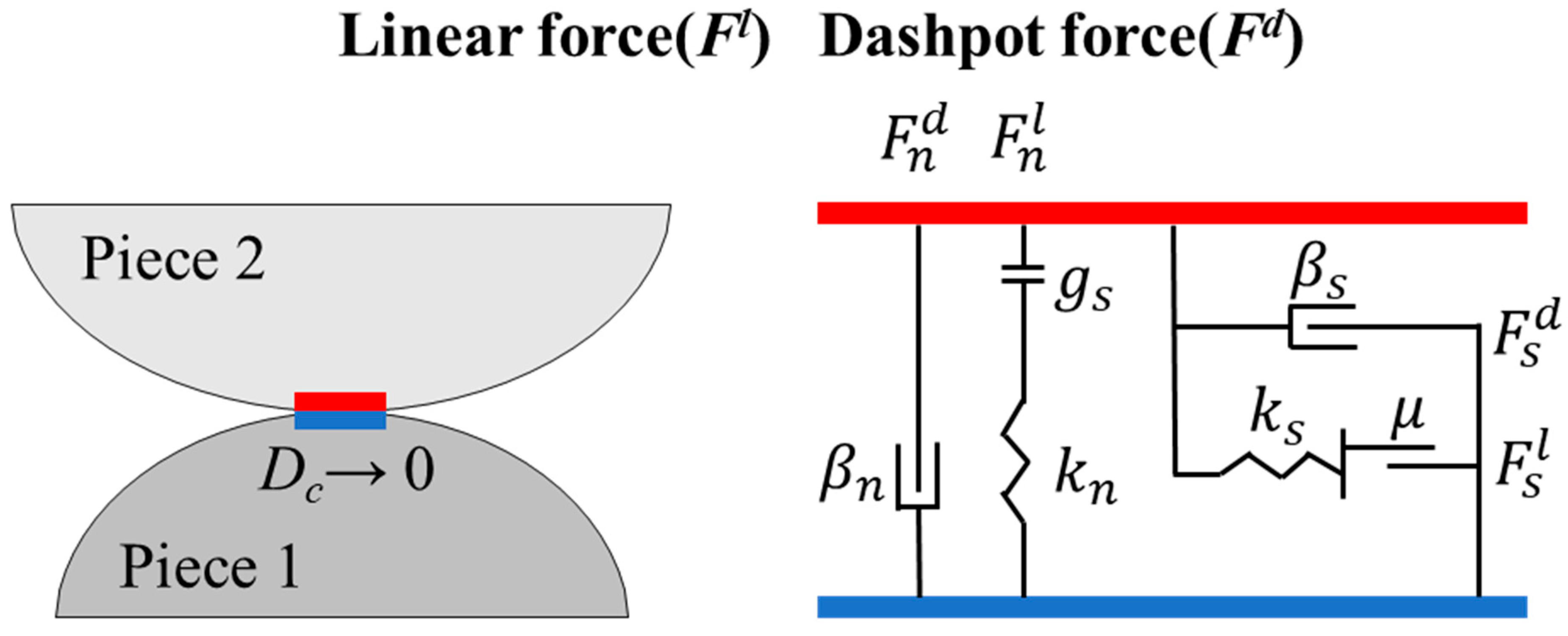
Figure 1. Schematic diagram of linear contact model.
Mathematics 11 02959 g001
Figure 2. Schematic diagram of particle surface gap in the linear contact model.
Mathematics 11 02959 g002
Figure 3. Specimen gradation curve.
Mathematics 11 02959 g003
Figure 4. Model specimen. (a) Model specimen; (b) Fine particles; (c) Coarse particles.
Mathematics 11 02959 g004
Figure 5. Variations in gradation of specimens after erosion.
Mathematics 11 02959 g005
Figure 6. Void ratios of model specimens with different degrees of erosion before and after loading under various confining pressure conditions.
Mathematics 11 02959 g006
Figure 7. Void ratios of model specimens with different degrees of erosion before and after loading under various confining pressure conditions. (a) Deviatoric stress-axial strain curve at the effective confining pressure of 100 kPa. (b) Deviatoric stress-axial strain curve at the effective confining pressure of 200 kPa. (c) Deviatoric stress-axial strain curve at the effective confining pressure of 400 kPa. (d) Deviatoric stress—axial strain curve at the effective confining pressure of 800 kPa.
Mathematics 11 02959 g007aMathematics 11 02959 g007b
Figure 8. Comparison of volumetric strain-axial strain curves for model specimens with different degrees of erosion. (a) Volumetric strain-axial strain curve at the effective confining pressure of 100 kPa. (b) Volumetric strain-axial strain curve at the effective confining pressure of 200 kPa. (c) Volumetric strain-axial strain curve at the effective confining pressure of 400 kPa. (d) Volumetric strain—axial strain curve at the effective confining pressure of 800 kPa.
Mathematics 11 02959 g008aMathematics 11 02959 g008b
Figure 9. Average particle coordination numbers of model specimens with different degrees of erosion before and after loading under various confining pressure conditions.
Mathematics 11 02959 g009
Figure 10. Critical state lines for model specimens with different degrees of erosion.
Mathematics 11 02959 g010
Table 1. Microscopic parameters of the model specimen.
Model ParametersValue
Particle density (kg/m3)2.65
Normal stiffness of particles 8 × 10⁴
Tangential stiffness of particles7 × 104
Damping factor of particles0.7
Friction coefficient of particles 0.2
Normal stiffness of walls 1 × 10⁸
Table 2. Parameters of critical state lines for specimens with various degrees of erosion.
Degree of Erosion0%2%4%6%8%10%
e τ 0.53450.54760.56120.57960.60450.6182
λ c 0.04840.05120.05390.05710.06200.0648
R20.99920.99970.99830.99970.99690.9938
Disclaimer/Publisher’s Note: The statements, opinions and data contained in all publications are solely those of the individual author(s) and contributor(s) and not of MDPI and/or the editor(s). MDPI and/or the editor(s) disclaim responsibility for any injury to people or property resulting from any ideas, methods, instructions or products referred to in the content.