1. Introduction
Modern turbomachine engineering demands the creation of bearings that ensure the stable, long-term rotation of a rotor at speeds of approximately 100,000 rpm and high temperatures, with large temperature differences within the rotor assembly, potential rotor imbalance, and base vibrations. Gas bearings with solid surfaces, fluid bearings, and rolling bearings are not effective under such conditions.
Initially, strip bearings were developed as a solution to create bearings with pliable surfaces. However, due to the tendency of the strips to stretch, their significant malleability, and their inability to compensate for distortions, they have not found significant application as high-speed rotor bearings.
The development of a petal gas-dynamic bearing (PGDB) that combines the idea of a bearing with a pliable surface and a bearing with self-aligning sector inserts dates back to 1963. A review of archival research focused on assessing the load characteristics quantitatively and the problem of ignoring accurate physical models in engineering practice is presented in [
1]. The stages of the development of gas-lubricated support structures are discussed in more detail in [
2]. Meanwhile, the current state of gas supports is considered in [
3], in which deeper research and systematization of experimental data are suggested. The study in [
4] provides an overview of the current state of gas bearing development in China. It highlights the application aspects of related technologies, such as coatings, production of elastic elements, and thermal regulation. The study in [
5] provides an overview of various models for the study of static and dynamic characteristics, and the authors formulate the key points and useful factors for overcoming rotor instability.
The main improvement areas of PGDBs include increasing the load-bearing capacity, reducing the starting torque, improving dynamic characteristics, and increasing durability. The characteristic features of improvement are an increase in the petal layer in the package, various geometric deviations on the support nodes, and additional elastic elements.
The influence of the standard deviation and arithmetic mean deviation of the surface profile on the startup characteristics of bearings made of metal rubber-bump foil is explored in [
6]. In contrast, Wang et al. [
7] created a model of unsteady lubrication with mixed air and wear for non-Gaussian surfaces. This model was able to predict the wear of the foil upper surface during startup. Liu et al. [
8] presented a model capable of analyzing the temperature distribution of the foil surface when the bearing was operated under conditions of ambient heat dissipation.
Unlike the previous works, [
9] investigated the influence of bearing compliance, external load, acceleration time, and contact rigidity on tribological properties during start-up. A transitional model taking into account the rarefaction of air was also presented in this source. The connected problem of gas-dynamics (finite volume method) and elasticity (variational approach) was solved.
Researchers created and analyzed a digital double of a thrust bearing in [
10]. The research was carried out using commercial software, and the experimental stand was used to analyze the performance characteristics of a specific bearing configuration.
The authors in [
11,
12,
13] describe the dynamic and static characteristics of impact-type radial bearings, to which [
14,
15,
16] are devoted. Within recent studies, simplified models that take into account the influence of the support parameters on the gaps between elastic elements are presented. Investigating different configurations of radial bearings in [
17], Li et al. developed a complex static structural model of a gas foil bearing with multiple sliding beams and studied the bearing characteristics. The authors then investigated the dynamic characteristics of this bearing with complex contact constraints in the following work [
18]. The analysis of design features affecting the nonlinear characteristics of the rotor and its stability was carried out.
The literature review presented above shows that the dynamic characteristics of bearings made of bump film have already been adequately studied. However, these developments may not be applicable to PGDBs due to the elastic elements having a completely different structure, making it necessary to study the dynamic characteristics of such bearings for their wider application.
In this article, a mathematical model has been constructed to study the dynamic characteristics of PGDBs, with a particular focus on the nonlinear dependency present in the bearing–rotor system. The Lagrange variational principle was employed to incorporate contact mechanics into the study of petal bearing dynamics, which makes it possible to further study dynamic characteristics with complex contact constraints. Additionally, models for the perturbations of elastic elements are presented, which are nonlinearly related to the equations of the gas film and the rotor’s motion.
The novelty of this study lies in the formulation of a mathematical model for PGDBs that considers nonlinear dependencies for the first time. The first static results of a load characteristics study for a flat bearing model are also established, whilst an experiment was conducted to study the rotor separation rate in relation to such a bearing.
2. Task of Calculating the Load Characteristics of Petal Bearings
The rotor maintains a constant angular velocity, with the rotation axis remaining stationary in relation to the housing. The radial load on the rotor remains constant over time and is balanced by the bearing reaction. The lubricating layer is present between the journal surface and the petals’ elastic surfaces, which are either rigidly or pivotally fixed to one edge of the bush. The other edges of the petals rests freely on the adjoining petals and there are no breaks in the lubricating layer. The magnitude of the bearing reaction is equal to the main vector of the pressure forces generated in the lubricating layer during the journal’s rotation. This value is called the load capacity of the bearing, and the dependence of the load capacity on the eccentricity of the journal is called the load characteristic of the PGDB.
Solving the equilibrium task involves determining the reaction value for a given equilibrium position of the rotation axis and a given angular velocity of the rotor, i.e., the load capacity. By using constructed dependencies of the load capacity on journal displacement and the angular velocity, we can determine the equilibrium position of the rotation axis at a given load on the rotor and a certain rotation speed. Additionally, we can determine whether the bearing is capable of balancing the given load on the rotor.
The elasticity task, or determining the elastic reactions of the petals that balance a given load on the rotor with a non-rotating journal, has independent significance due to the petals’ reduced rigidity in the “lubricating layer—elastic shells” system. The package of petals determines the system’s rigidity as a whole and the load characteristics type of the bearing. The dependence of the petals’ elastic reaction on the journal displacement with a non-rotating rotor is called the static load characteristic of the bearing.
2.1. Initial Equations in the Pressure Task
The clearance shape in the bearing significantly determines the pressure distribution in the lubricating layer of a gas-dynamic-type bearing. In a petal bearing, one of the boundaries of the lubricating layer is deformed by the pressure developed in the layer. Finding the reactions of such a bearing requires a joint solution of the pressure task in the layer and the deformation task of the petals under pressure. This task falls into the class of elastic–gas-dynamic tasks.
The gas movement in the clearance is determined by the combined action of pressure, mass, and viscosity forces. While mass forces in the gas are relatively small, viscosity forces become significant in a thin clearance that narrows in the direction of the journal surface’s relative velocity ) with a sufficiently high relative velocity.
When examining the lubricant’s flow within the bearing clearance, the following conditions are assumed:
The thickness of the lubricating layer (
) is significantly smaller then the length of the layer (
:
In a petal bearing, the value of may be greater than in an ordinary gas-dynamic bearing, but condition (1) is still satisfied with .
- 2.
The thermal regime in the lubricating layer is isothermal. In this case, the density (
) and the gas pressure (
) are related by the equation of state through the coefficient
:
- 3.
When the lubricant‘s flow is laminar, the forces of inertia of the lubricant can be neglected. This assumption is related to the estimation of the Reynolds number (
Re) for the layer and the assumption that the thickness of the lubricating layer changes smoothly enough:
where
is the characteristic speed,
is the dynamic viscosity of the surroundings, and
is the layer length. Condition (3) is mostly assumed for PGDBs, but it is worth noting that local values of
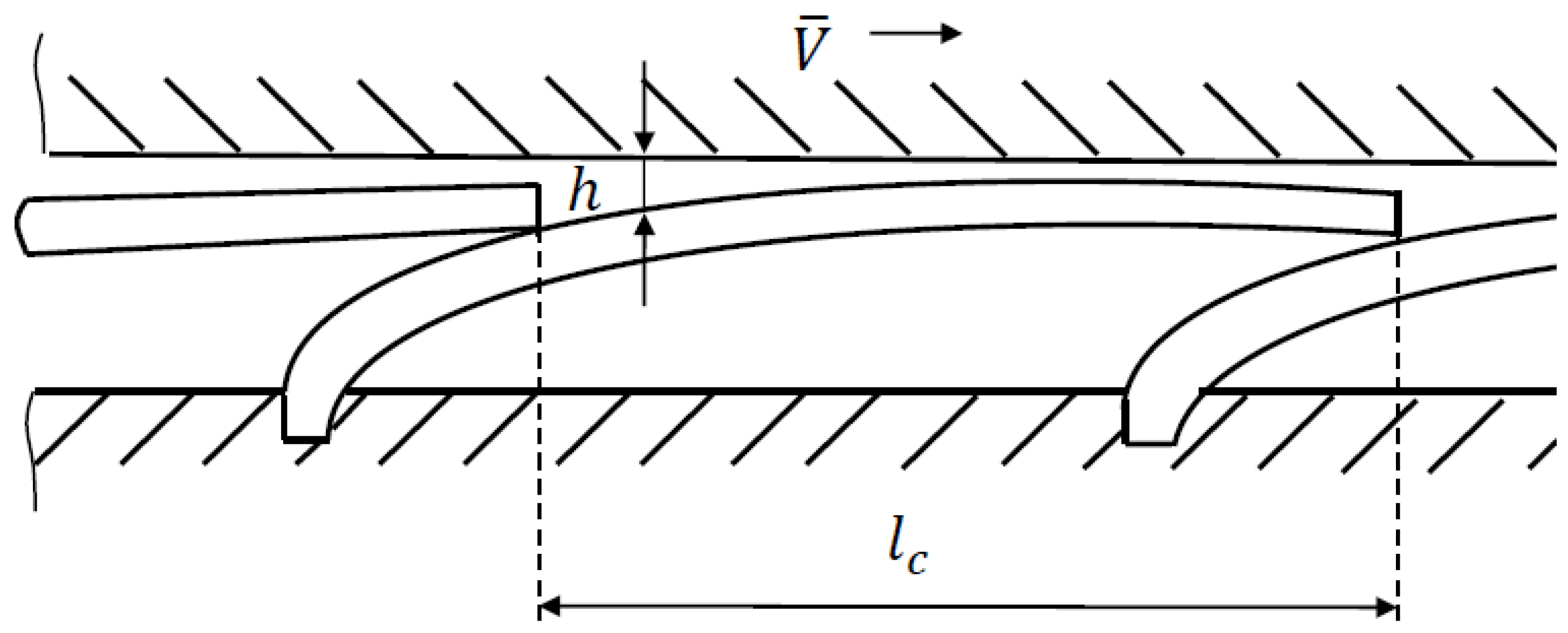
Re for the area taken in the vicinity of the left boundary of the layer (
Figure 1) can have values of the order of one.
Conditions (1)–(3) are commonly accepted in the gas lubrication theory. It should be noted that they are not always absolutely fulfilled in the aggregate for PGDBs.
By making assumptions (1)–(3) while considering the Navier–Stokes equation together with the continuity equation, the pressure distribution in dimensionless quantities from the Reynolds equation can be found:
where
is the radial coordinate, Λ is the compressibility parameter of the medium,
is the thickness of the lubricating layer; and
is the gas pressure.
Given that the clearance on the left border of the layer is large (in the order of the petal thickness) in a bearing with overlapping petals, the boundary conditions for pressure are taken as conditions for open borders:
When considering the lubricant’s flow in the bearing’s clearance, we assume that the boundary conditions (5) can contain inaccuracies that are difficult to estimate. This is because the gas flow in the boundary region at the high surface movement speeds of the journal does not strictly satisfy condition (3), so the ratio (3) may be violated and there is a drastic change in the layer thickness. Constantinescu’s results [
19] suggested that during lubrication inertial effects are locally manifested in regions with sudden changes in layer thickness, which do not significantly affect the pressure distribution. It is assumed that inaccuracies in the boundary conditions (5) will affect the lubrication flow locally in marginal areas without significantly changing the pressure distribution’s integral characteristics.
2.2. Variational Approach to Solving the Elasticity Task
In the petal shell system, the conditions of the petals’ contact with the limiters of their movements are not known in advance, and the contact areas can change their positions when the journal is moving. To solve the problem of finding the equilibrium configuration of a system of elastic, deformed shells, a variational approach is required.
The petals can be treated as a system that is mechanically subordinate to one-sided connections expressed by inequalities. The system of active forces is determined by a combination of internal elastic forces and external load forces. The virtual movements,
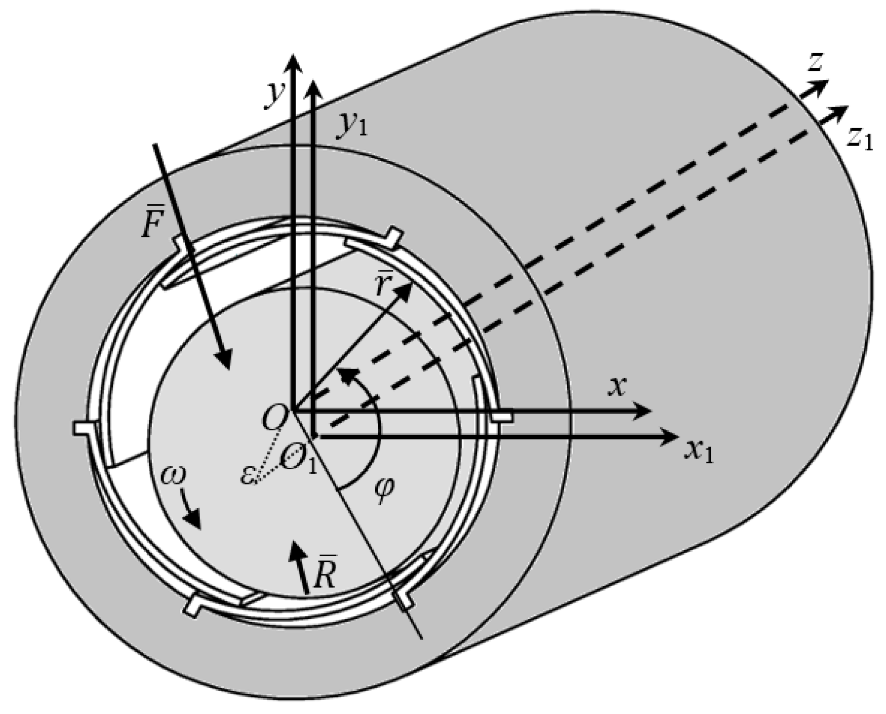
, of the petals’ points from the equilibrium configuration with contacts are one-sided, and the reactions of one-sided connections are co-directed with virtual movements (
Figure 2).
Now the most common principle of balance of a mechanical system must be considered—the principle of virtual displacements for systems with one-way connections.
For the l-th petal:
is the virtual operation of elastic forces, and ( = 2) is the virtual operation of the specified load forces to be determined.
In accordance with the principle of virtual displacements from an equilibrium configuration, it is necessary and sufficient to require the fulfillment of the condition:
for one-way virtual displacements in the area with contacts, and the condition:
in the area without contacts.
To define the potential energy, virtual differentials of potential deformation energy (
) and potential load energy (
) are introduced:
When solving the elasticity task, the load is considered independent of the desired deflections. So, the external forces in the considered equilibrium task are potential. The following equation is introduced:
where
is the total potential energy of the petal.
The virtual displacement principle conditions (6) and (7) can be expressed as equation:
for one-way virtual displacements on contacts, and equation
for two-way virtual displacements in an open area (without contacts). In Equations (11) and (12)
represents the variation of the potential energy when the petal moves from the equilibrium configuration to the adjoining one, allowed by connections.
The elastic contact of adjoining petals
and
(
Figure 2) can occur as either one-way virtual movements,
,
, where the condition must be met for each of the petals (11), or as two-sided joint variations,
, which are assumed during elastic contact. In the equilibrium deformed configuration of the petal shell system, the potential energy of the system must be stationary, which is equal to the sum of the potential energies of the petals:
It was proven in previous work [
20] that for a linearly elastic body with retaining limitations, the second variation of the potential energy is
.
The equilibrium configuration can be obtained using the Lagrange principle, which states that for an elastic body system constrained by limitations (contact task), the system’s potential energy must reach its lowest value in the range of acceptable connections of elastic displacements for a particular configuration to be balanced in the task.
3. Calculation of the Load Capacity of the Petal Gas-Dynamic Bearing
In this study, the following assumptions were made:
The petal is a thin elastic cylindrical shell, for which the Kirchhoff–Love hypotheses are valid;
The median line of the petal is inextensible;
Elastic displacements of the petal are considered small, and the deflection problem is viewed as geometrically linear;
The surfaces limiting the elastic displacements of the petals (the surfaces of the shaft and the bushing) are smooth and absolutely rigid;
The axis of the pin is parallel to the bearing axis;
The gas layer is thin, inertia-less, isothermal, continuous, and laminar.
3.1. Bearing Geometry
The task of determining the load-carrying capability of a bearing of finite dimensions was considered. A cylindrical coordinate system,
Orz, was introduced in reference to the bearing’s bushing (
Figure 3). The median surface
) of the undeformed petal is described by the following relationship:
Moreover, the ratios are fair:
If conditions (15) are met, the Lame coefficients of the median surface can be represented as:
It also follows from conditions (15) that for a point arbitrarily taken on the median surface of the lobe, the angle (
γ) between the normal to the surface (
) and the radius vector (
) drawn to this point is small. Assuming that the normal movements of the median surface of the petal,
, coincide with the radius vector (
), then the equation of the deformed surface can be expressed as:
For the deformed median surface of the petal, the normal to the median surface and the radius vector () are also considered to coincide for any point on the petal surface.
3.2. The System of Restrictions for Deflections
The geometric relations in the bearing naturally determine the restriction system for deflections, with the following conditions:
Clearance,
between the surfaces of the journal and the petal is given by:
where
is the petal thickness,
is the radius of the journal (shaft), and
is the eccentricity of the journal displacement.
No cutting into the surface of the bearing bushing:
where
is the bearing bushing radius.
Mutual non-penetration of the surfaces of adjoining petals
,
:
From conditions (18) and (19), the following restriction system on deflections is obtained:
where
is the petal thickness without coating,
is the petal angle,
is the angle from the overlap point of
petal and
, and
is the petal
overlap angle of petal
.
Expressions (20)–(22) define the geometric limitation system on the petal deflections.
3.3. Boundary Conditions for Deflections
In the
,
coordinate plane, the petal occupies an area of
with border
(
Figure 4).
The boundary conditions on the petal contour can be defined as:
- (a)
on the line
attachment of the petal with the bushing
with the rigid attachment
with the hinge mount for bending moment
where
is Poisson’s ratio.
- (b)
on line
for bending moments
- (c)
on line
for leaning edge
It follows from (23) that for the petal attachment line
For line
from (26) the following is obtained
In points
For line
condition (27) is satisfied and, therefore
For points
from (25), (29), the following is obtained
3.4. Potential Energy of the Petals Package
Considering the petal as a thin (
), linearly elastic shell with constant thickness, for which the Kirchhoff–Love hypotheses are accepted, an inaccuracy of the order
can be introduced, where
is a minimum linear size of the median surface. In this case, the deformation energy of the shell bending is equal to:
where
are the main curvatures of the median surface, and
and
are the velocities in the directions
and
accordingly.
Considering the condition of inextensibility of the median surface as
the following is obtained
and considering the conditions (16), the following is obtained
Substituting (38) into (33),
for the system of petal can be found
where
is the Poisson’s ratio of the petal material.
The external load for the shell system is the excess pressure,
, the potential of which is equal to:
where
is the excess pressure of the lubricating layer of petal
l;
is the pressure in the lubricating layer of petal
l; and
is the ambient pressure.
The potential energy of the shell system is equal to the sum of the bending deformation energy (
) (39) and the potential of the external load (
) (40):
3.5. Approximation of the Potential Energy
The expression of the potential energy (
E) (41) in dimensionless quantities is given by:
where
is the montage clearance.
In the area
where petal coordinates
change, a grid
is introduced:
where
is the dimensionless length of the bearing bushing.
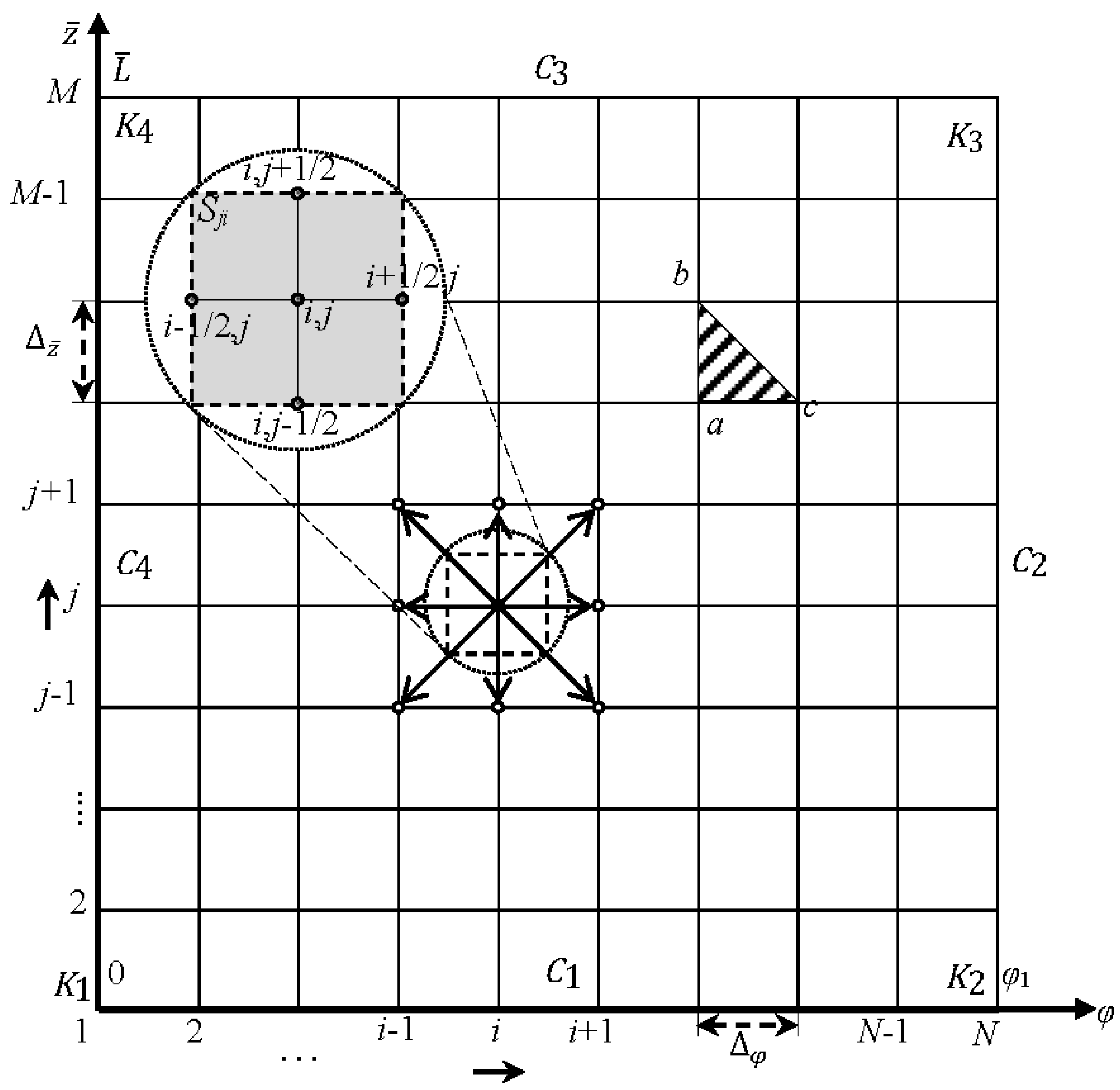
Integration is carried out on triangular elements
(
Figure 4). On the selected element, the integrand function (
,) is approximated by a plane that passes through the relevant nodal points:
where
,
, and
are values of the function at the vertices of the triangle
abc (
Figure 4).
Using (44), the potential energy
can be replaced with finite-difference analog
:
where
,
is petal symmetry line.
where
is the dimensionless coefficient of cylindrical rigidity,
is the coefficient of cylindrical rigidity of the petal,
is Young’s modulus (modulus of elasticity) of the petal material, and
Obviously, for any node there is some finite set of nodes , for which . This set of nodes forms a 9-point pattern.
Considering the selected areas of influence, the values of gradients at the nodes of variation are determined by:
where
The task of determining the equilibrium deformed configuration for the petal shell system is posed as the task of determining the smallest value () of the shell system’s potential energy under known limitations (18)–(22) and the given external load.
3.6. Calculation of the Pressure in the Lubricating Layer
To determine the stationary pressure distribution in the lubricating layer, the idea of calculating the time setting was used. The equation for the pressure distribution in a non-stationary form can be written as:
where the boundary conditions for the pressure of the open boundaries layer are:
For an arbitrary internal node
of a grid
an area
is selected, within which Equation (51) is integrated, taking into account (53):
In the left part of Equation (54), using Green’s formula, it is proceeded to the contour integral and, taking into account the specified bypass direction (
Figure 4), the following is obtained:
where
The right part of Equation (54) is approximated by the expression:
where
k—is the layer number by time.
Referring the left part of Equation (54) to the
k-th time layer, an explicit scheme for integrating the equation in time (51) is obtained:
with the approximation order
. Scheme (58) is explicit because
are expressed explicitly through
.
The stability of the scheme is guaranteed by the choice of the step
:
where
is achieved at the inlet to the lubricating layer at
.
The stability analysis of the scheme in accordance with was conducted on a grid, , while varying the parameters (43) . The scheme achieved stable convergence when the values of were reached.
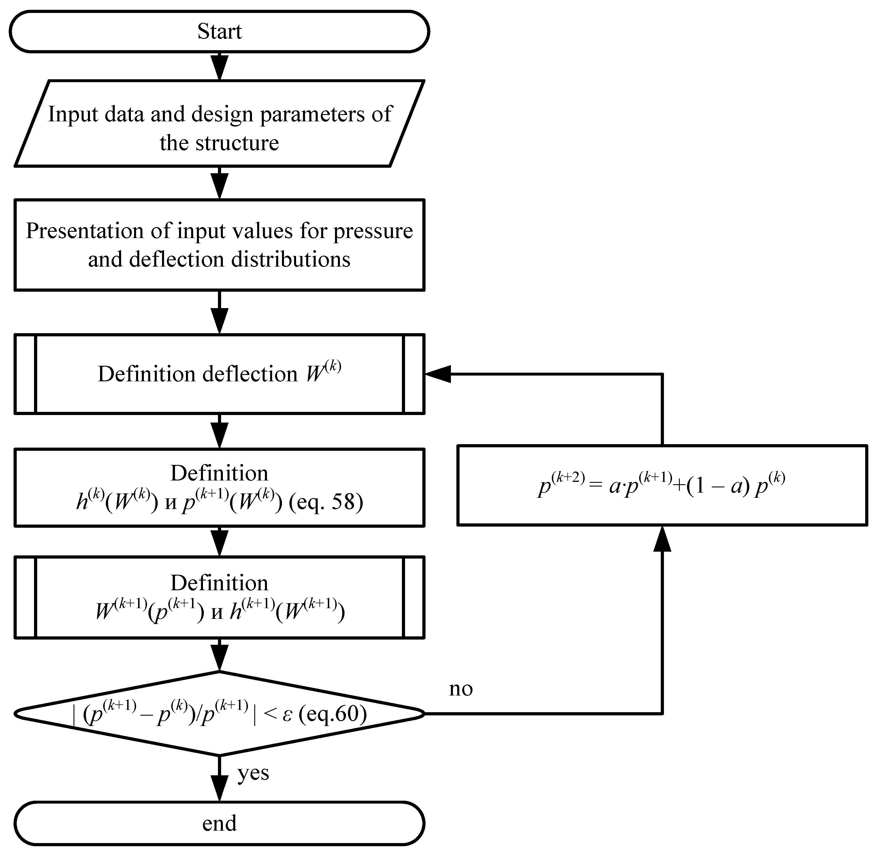
According to the described methodology, an algorithm was developed (
Figure 5) for solving a joint elastic–gas-dynamic task:
Input of initial data and calculation parameters of the structure.
Construction of input values of pressure distribution and deflections.
Determination of the equilibrium configuration of the deformed petals package.
Based on the obtained deflection distribution, the clearance value is determined, according to which the pressure distribution is determined.
Determination of and .
Checking the convergence condition:
at which the iterative process ends.
If condition (60) is not met, then the pressure distribution relaxation procedure is performed: , followed by step 3.
To accelerate the convergence of the iterative “pressure–deflection” process at the given journal position, a relaxation technique can be used to determine the deflections:
where
is the input deflection value,
is the output deflection value,
n is an iteration number, and
is the relaxation coefficient (different from the pressure relaxation coefficient).
3.7. Load Capacity of the Bearing and the Task of Dynamics
The projections
of the main vector of excess pressure forces acting on the journal are defined by:
Using an approximation (44) and the grid
, the following is obtained in dimensionless quantities:
The module of the main vector of pressure forces (load characteristic):
The angle of the journal position
To determine the trajectory of the journal center, the equation for calculating the dynamic characteristics can be presented as a system of equations in dimensionless form obtained by projecting the corresponding forces on the coordinate axes
and
(
Figure 3):
where
is the dimensionless mass of the rotor;
,
are dimensionless coordinates of the center of the journal;
,
are dimensionless projections of the reaction force of the lubricating layer;
is the dimensionless external force acting on the journal; and
is the dimensionless gravity of the rotor directed in the opposite direction of the
axis.
3.8. Implementation of the Mathematical Model
At the initial stage, the considered spatial mathematical model (in the space ) was reduced to a flat model in the space . The considered flat bearing model had parameters: ; ; ; ; ; ; and , c−1.
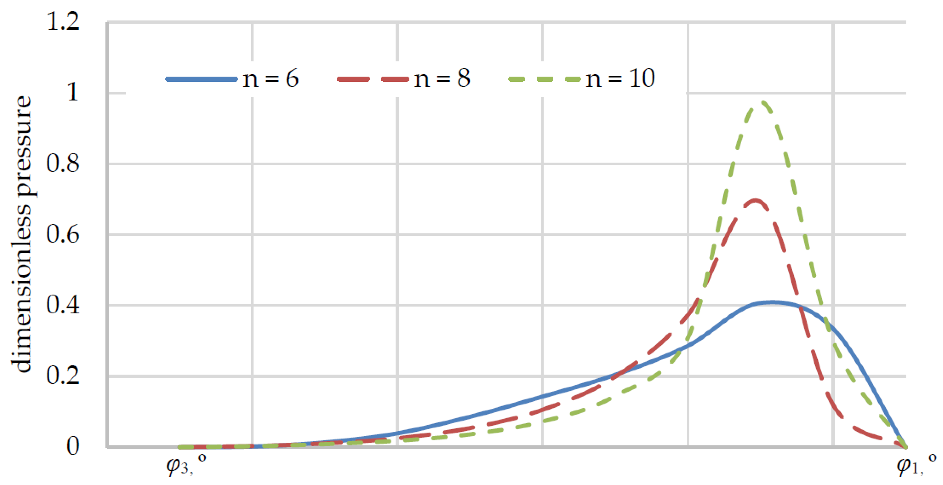
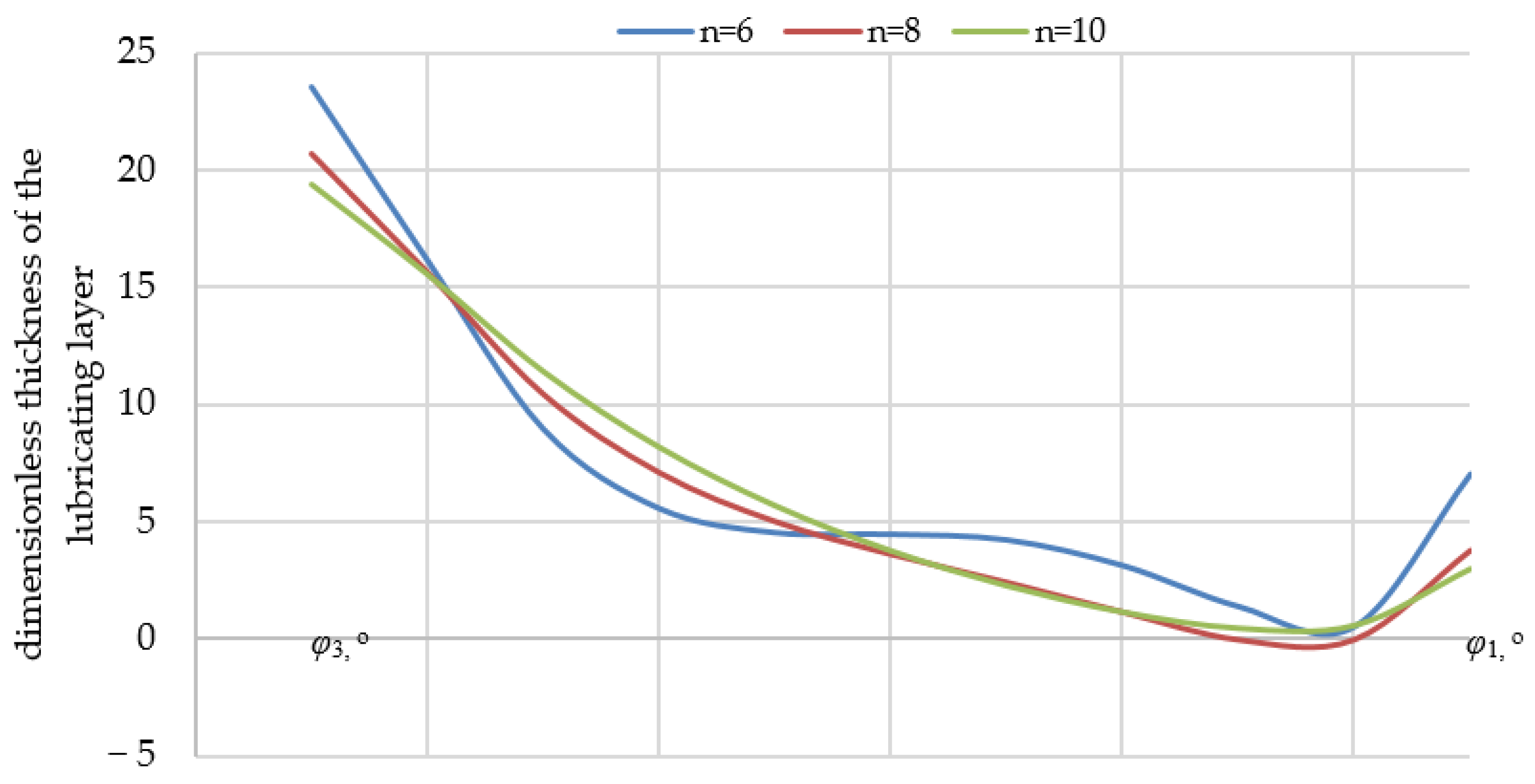
At the first stage of numerical modeling, an unloaded bearing was studied with the journal in a central position (
), while varying the number of petals
n = 6, 8, 10. Pressure values (
Figure 6) and the thickness of the lubricating layer (
Figure 7) were determined in the region of radial angle variation
(area without overlap between petal
and previous petal
).
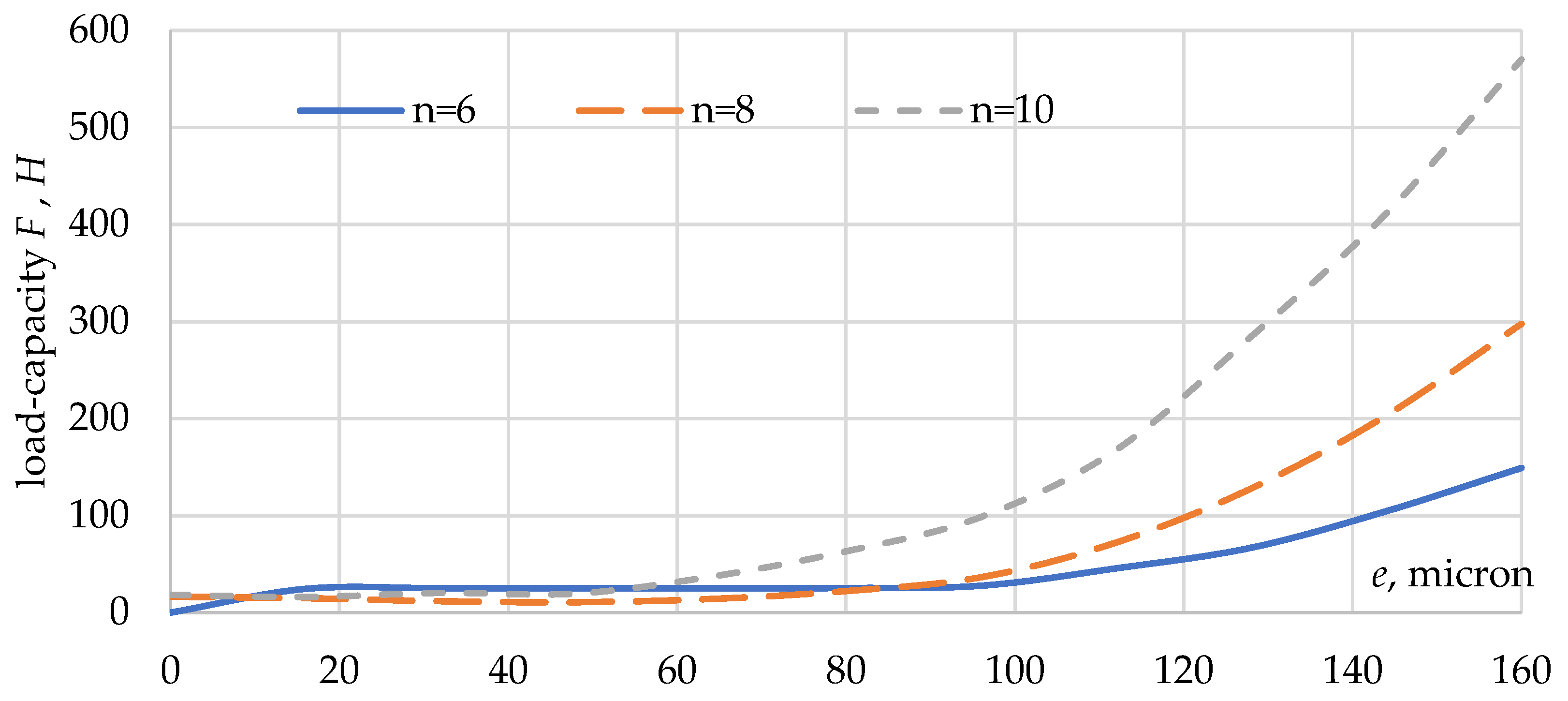
Additionally, with a different number of petals (
n), the dependence of the load capacity (
F) of the bearing on the eccentricity of the shaft (
e) was obtained (
Figure 8).
Based on the results, it could be concluded that increasing the number of petals (n) in the package from 6 to 10 led to almost a two-fold increase in the load characteristic value.
The methodology presented in this article had several advantages, including fast convergence, no need for high computational capabilities (a PC was sufficient), and a calculation accuracy of . A further increase in accuracy did not lead to an improvement in results.
This methodology can be used to optimize parametric studies of PGDB load characteristics.
The described technique and obtained results were used to estimate the rate of ascent of the bearing in the PGDB for various levels of shaft loading.
4. Experimental Studies
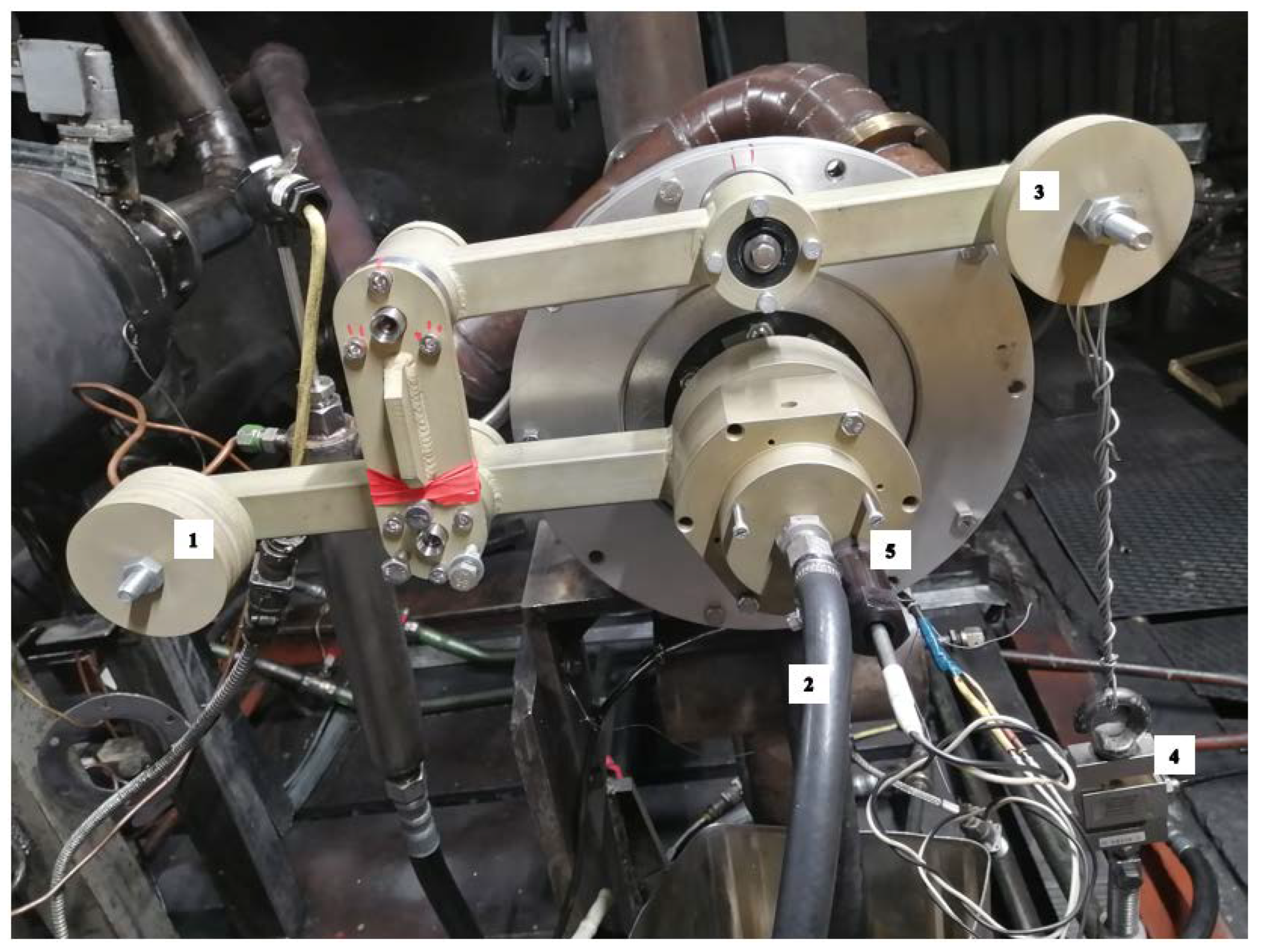
The shaft ascent rate was studied in order to obtain the experimental characteristics of the bearing–rotor system. The experiment was carried out on the installation (
Figure 9), that was developed at SCB “Turbina”. The gas-dynamic bearing was operated at the critical rotor speed while maintaining specific parameters: the outer radius of the bushing was 36.5 mm; the inner radius of the bearing bushing was 28.975 mm; the bearing length was 76 mm; the radius of the bending petals was 45 mm; the thickness of the petal was 0.15 mm; and the coating of the petals was 12...20 microns.
The installation setup (
Figure 9) involved a turbocharger shaft equipped with a PGDB, which was fitted with a biaxial structure weighing 5661 kg along with adjustable masses
m1 and
m2, fixed to the pins (1, 3) of the turbine (2) and on the bearing bushing. A speed sensor (5) and an air-cooling system (
P = 2.84 kPa) were also connected to the structure. The strain gauge force sensor (4) was connected to a pin with mass
m2.
Initially, the PGDB “lay” on the shaft driven by an axial rolling bearing. By increasing the rotor speed, an air wedge effect was created in the bearing causing it to “emerge”, thus creating an air clearance between the shaft surface and the petals package. At the moment of ascent, the force sensor (4) showed the maximum (peak) value.
During the experiments, the number of loads fixed on pins (1) and (3) changed. After loading, the shaft was accelerated with an increase in the number of rotations to 30,000 rpm. Each experiment included several parallel experiments. The results of the experiment and the values of the ascent velocity are summarized in
Table 1.
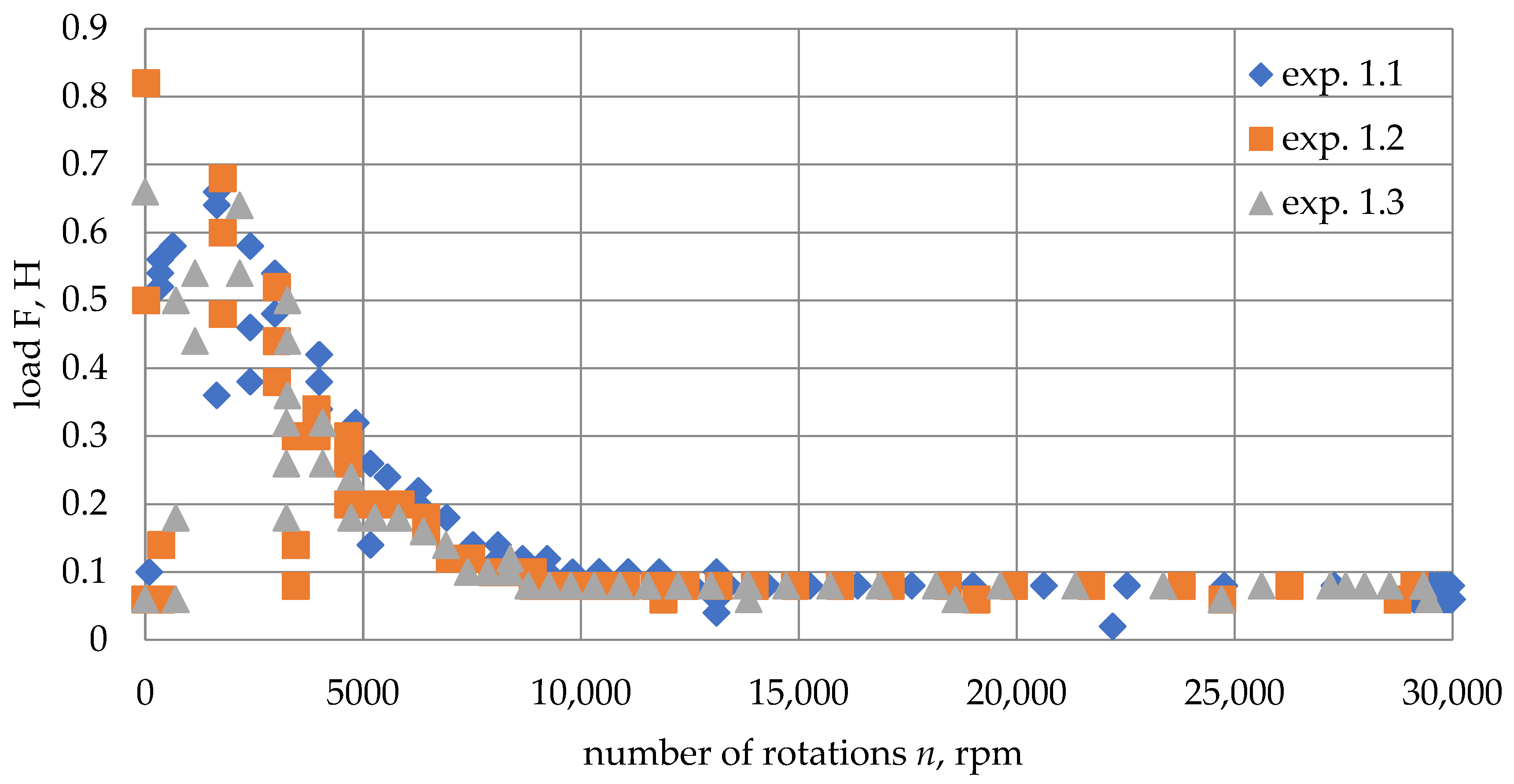
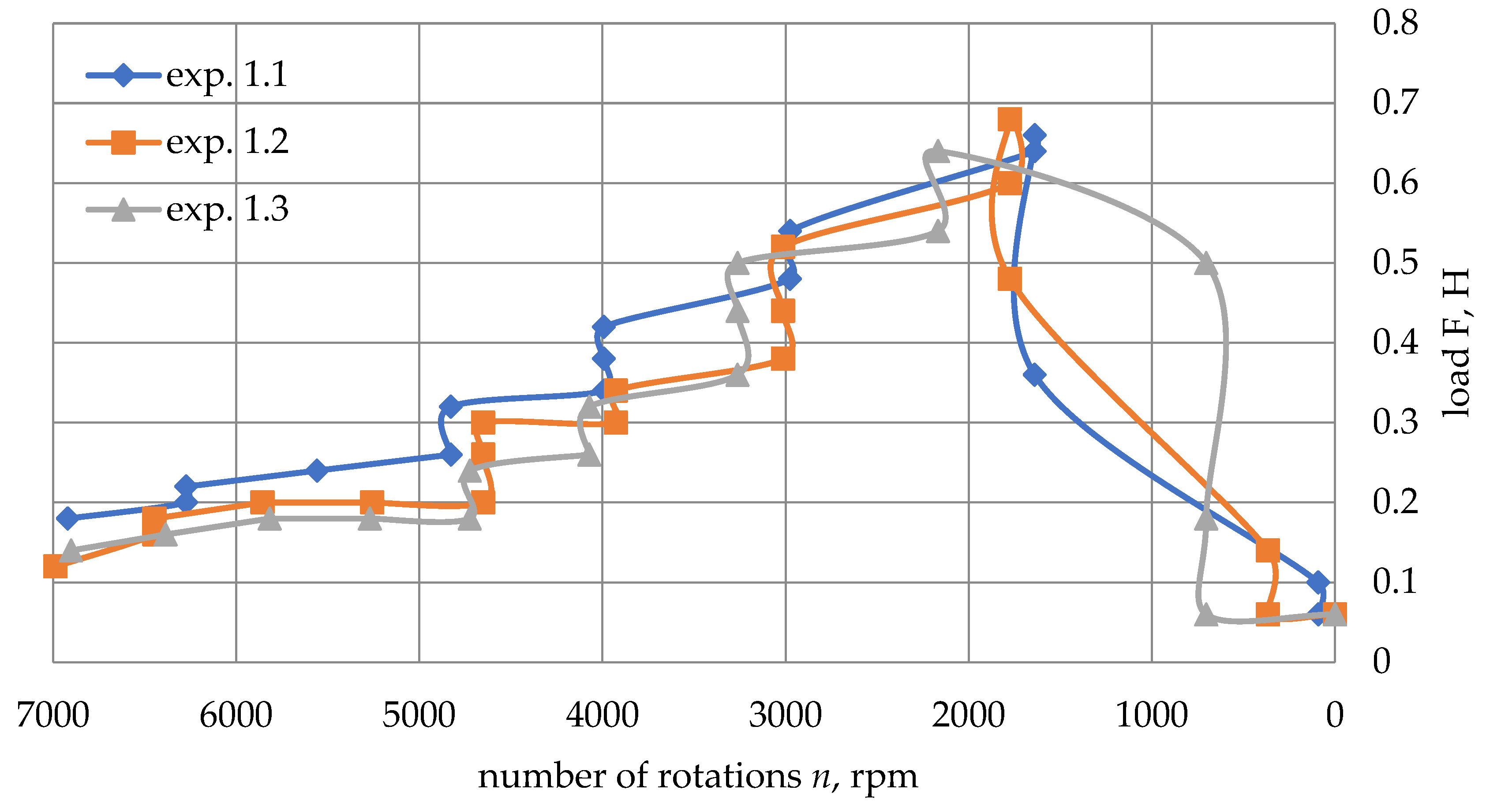
According to the results of experiment 1, the loading force of the journal was dependent on the angular velocity during acceleration (
Figure 10) and braking (
Figure 11):
In experiments 1, 2, and 3, steady ascent of the rotor was observed. In the fourth experiment (exp. 4), it was decided to test the maximum load that the bearing could withstand.
During experiment 4.2, the bearing surfaced, but it began to descend on the 13th s. The maximum value of the force measured by the dynamometer was 2.42 kgf, so it was decided to stop testing under such load.
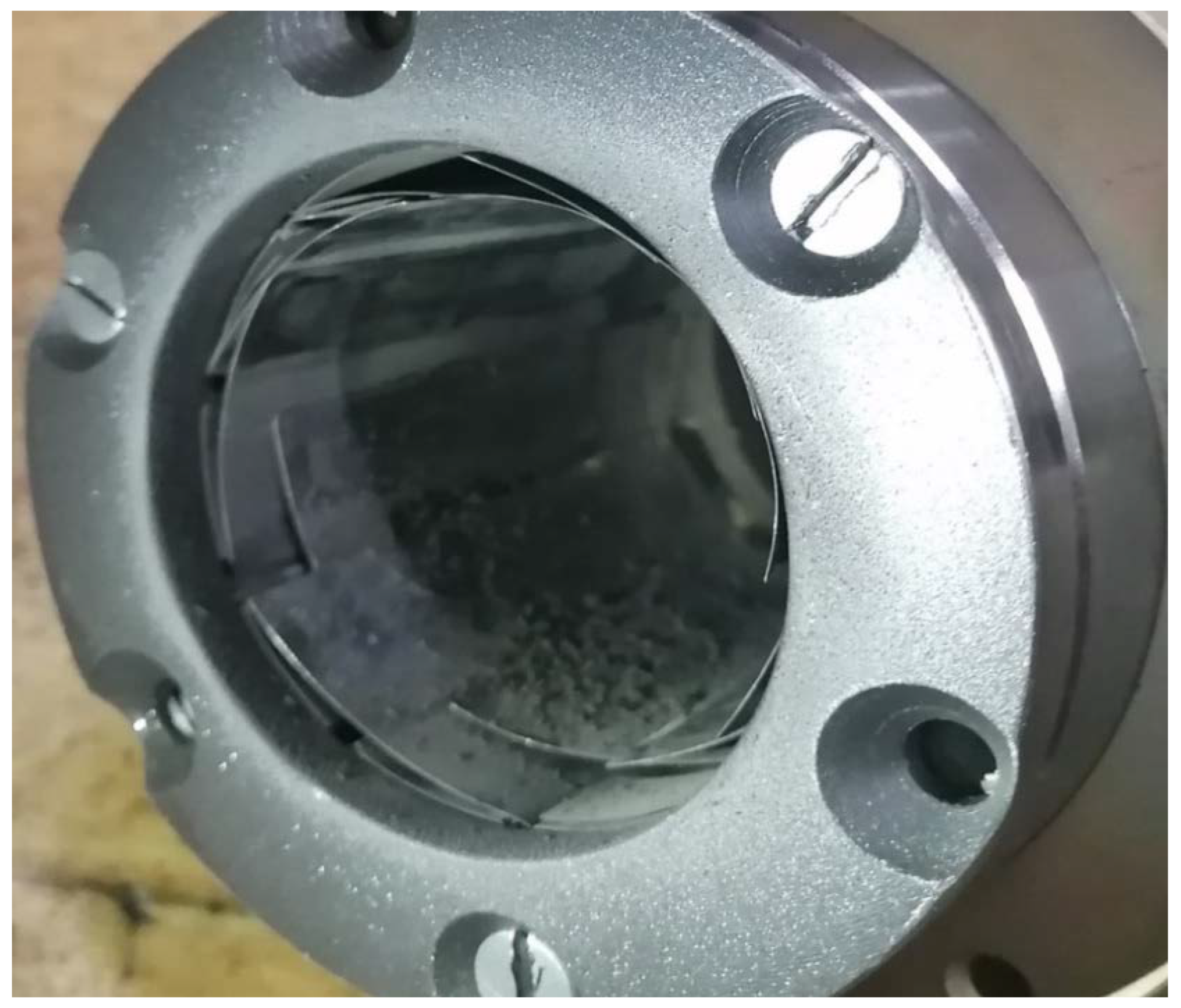
External inspection revealed carbon deposits on the petals of the gas-dynamic bearing (
Figure 12), making them unsuitable for further testing.
