

Efficient Index Modulation-Based MIMO OFDM Data Transmission and Detection for V2V Highly Dispersive Channels

 ,
,  ,
,  and
and
Abstract
1. Introduction
- (i)
- A novel IM-MIMO-OFDM system based on QSM is proposed for handling doubly selective MIMO-V2V channels.
- (ii)
- The MIMO receiver developed here maintains a structure and computational complexity lower than the conventional MIMO-OFDM receiver.
- (iii)
- The proposed system demonstrates high robustness against uncertainties in channel statistics, achieving a low BER even at high levels of Doppler frequency dispersion.
Notation
2. System Model MIMO-OFDM-IM
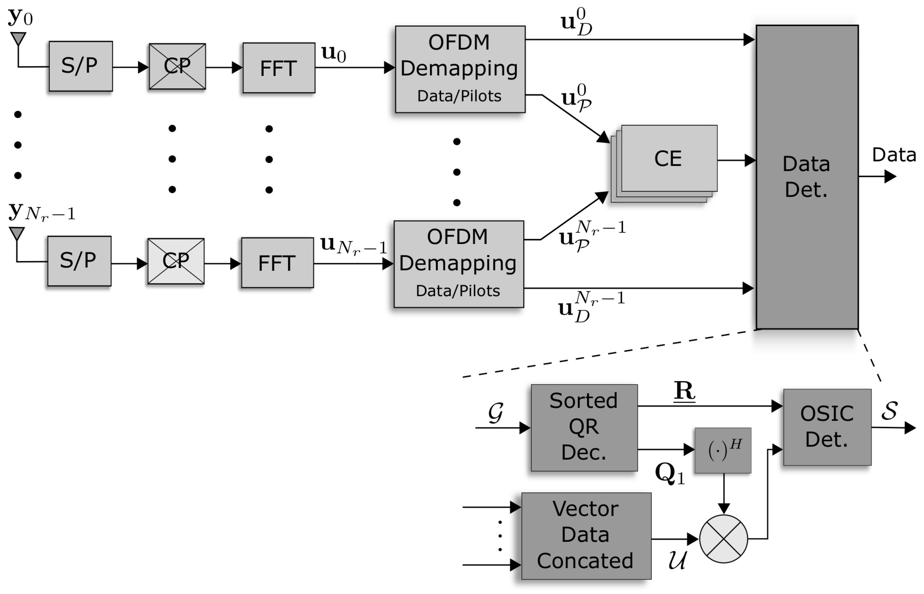
3. Receiver
3.1. Channel Estimation
3.2. Low-Complexity Detection for OFDM-IM Signals
| Algorithm 1: Sorted QR decomposition. |
 |
OSIC-MMSE Sorted Detection
| Algorithm 2: Proposed OSIC algorithm. |
 |
4. Computational Complexity
5. Performance Analysis
5.1. Experiment 1
5.2. Experiment 2
5.3. Experiment 3
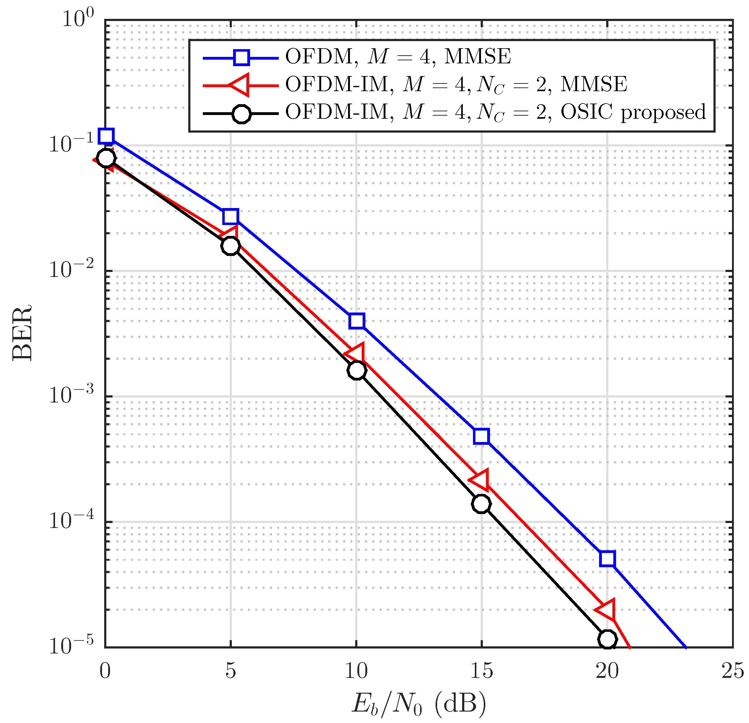
5.4. Experiment 4
5.5. Experiment 5
6. Conclusions
Author Contributions
Funding
Data Availability Statement
Conflicts of Interest
References
- Jiang, H.; Zhang, Z.; Dang, J.; Wu, L. A Novel 3-D Massive MIMO Channel Model for Vehicle-to-Vehicle Communication Environments. IEEE Trans. Commun. 2018, 66, 79–90. [Google Scholar] [CrossRef]
- Basar, E. On Multiple-Input Multiple-Output OFDM with Index Modulation for Next Generation Wireless Networks. IEEE Trans. Signal Process. 2016, 64, 3868–3878. [Google Scholar] [CrossRef]
- Yang, M.; Ai, B.; He, R.; Chen, L.; Li, X.; Li, J.; Zhong, Z. V2V channel characterization and modeling for underground parking garages. China Commun. 2019, 16, 93–105. [Google Scholar] [CrossRef]
- Alghorani, Y.; Seyfi, M. On the Performance of Reduced-Complexity Transmit/Receive-Diversity Systems Over MIMO-V2V Channel Model. IEEE Wirel. Commun. Lett. 2017, 6, 214–217. [Google Scholar] [CrossRef]
- Ma, N.; Chen, J.; Zhang, P.; Yang, X. Novel 3-D Irregular-Shaped Model for Massive MIMO V2V Channels in Street Scattering Environments. IEEE Wirel. Commun. Lett. 2020, 9, 1437–1441. [Google Scholar] [CrossRef]
- Jiang, H.; Zhang, Z.; Wu, L.; Dang, J. Novel 3-D Irregular-Shaped Geometry-Based Channel Modeling for Semi-Ellipsoid Vehicle-to-Vehicle Scattering Environments. IEEE Wirel. Commun. Lett. 2018, 7, 836–839. [Google Scholar] [CrossRef]
- Longoria-Gandara, O.; Parra-Michel, R. Estimation of Correlated MIMO Channels using Partial Channel State Information and DPSS. IEEE Trans. Wirel. Commun. 2011, 10, 3711–3719. [Google Scholar] [CrossRef]
- Gutiérrez, C.A.; Harrison, W.; Rice, M.; Jensen, B.; Norman, K.; Redd, B.; Twitchell, A.; Cardenas-Juarez, M. Envelope distribution and Doppler spectrum of V2V channels at 5.9 GHz in mountainous roads. Veh. Commun. 2023, 39, 100570. [Google Scholar] [CrossRef]
- Gómez-Vega, C.A.; Cardenas, J.; Ornelas-Lizcano, J.C.; Gutiérrez, C.A.; Cardenas-Juarez, M.; Luna-Rivera, J.M.; Aguilar-Ponce, R.M. Doppler Spectrum Measurement Platform for Narrowband V2V Channels. IEEE Access 2022, 10, 27162–27184. [Google Scholar] [CrossRef]
- Basar, E.; Aygolu, U.; Erdal, P.; Poor, H.V. Performance of Spatial Modulation in the Presence of Channel Estimation Errors. IEEE Commun. Lett. 2012, 16, 176–179. [Google Scholar] [CrossRef]
- Castillo-Soria, F.R.; Cortez-Gonzalez, J.; Ramirez-Gutierrez, R.; Maciel-Barboza, F.M.; Soriano-Equigua, L. Generalized Quadrature Spatial Modulation Scheme Using Antenna Grouping. Etri J. 2017, 39, 707–717. [Google Scholar] [CrossRef]
- Li, J.; Li, Q.; Dang, S.; Wen, M.; Jiang, X.Q.; Peng, Y. Low-Complexity Detection for Index Modulation Multiple Access. IEEE Wirel. Commun. Lett. 2020, 9, 943–947. [Google Scholar] [CrossRef]
- Cortez, J.; Gutiérrez, C.A.; Castillo-Soria, F.R.; Luna-Rivera, J.M.; Maciel-Barboza, F.M.; Ruiz, E. Performance Evaluation of Spatial Modulation Techniques in Correlated MIMO V2V Channels. In Proceedings of the 2018 IEEE Colombian Conference on Communications and Computing (COLCOM), Medellin, Colombia, 16–18 May 2018; pp. 1–6. [Google Scholar] [CrossRef]
- Kansal, L.; Berra, S.; Mounir, M.; Miglani, R.; Dinis, R.; Rabie, K. Performance Analysis of Massive MIMO-OFDM System Incorporated with Various Transforms for Image Communication in 5G Systems. Electronics 2022, 11, 621. [Google Scholar] [CrossRef]
- Huo, Y.; Lin, X.; Di, B.; Zhang, H.; Hernando, F.J.L.; Tan, A.S.; Mumtaz, S.; Demir, Ö.T.; Chen-Hu, K. Technology Trends for Massive MIMO towards 6G. arXiv 2023, arXiv:2301.01703. [Google Scholar]
- Basar, E.; Wen, M.; Mesleh, R.; Renzo, M.D.; Xiao, Y.; Haas, H. Index Modulation Techniques for Next-Generation Wireless Networks. IEEE Access 2017, 5, 16693–16746. [Google Scholar] [CrossRef]
- Mrkic, J.; Kocan, E.; Pejanovic-Djurisic, M. Index modulation techniques in OFDM relay systems for 5G wireless networks. In Proceedings of the 2017 40th International Conference on Telecommunications and Signal Processing (TSP), Barcelona, Spain, 5–7 July 2017; pp. 208–211. [Google Scholar] [CrossRef]
- Bai, Z.; Peng, S.; Zhang, Q.; Zhang, N. OCC-Selection-Based High-Efficient UWB Spatial Modulation System over a Multipath Fading Channel. IEEE Syst. J. 2018, 13, 1181–1189. [Google Scholar] [CrossRef]
- Mao, T.; Wang, Q.; Wang, Z.; Chen, S. Novel Index Modulation Techniques: A Survey. IEEE Commun. Surv. Tutorials 2019, 21, 315–348. [Google Scholar] [CrossRef]
- Huang, G.; Ding, Y.; Ouyang, S.; Fusco, V. Index modulation for OFDM RadCom systems. J. Eng. 2021, 2021, 61–72. [Google Scholar] [CrossRef]
- Eren, T.; Akan, A. Null Subcarrier Index Modulation in OFDM Systems for 6G and Beyond. Sensors 2021, 21, 7263. [Google Scholar] [CrossRef]
- Athisaya Anushya, T.W.E.; Laxmikandan, T.; Manimekalai, T. Group-indexed orthogonal frequency division multiplexing index modulation aided performance trade off. Etri J. 2022, 44, 105–116. [Google Scholar] [CrossRef]
- Jain, M.; Makkar, R.; Rawal, D.; Gangopadhyay, R. Dual-mode index modulation based OFDM system over NOMA networks. Phys. Commun. 2021, 47, 101395. [Google Scholar] [CrossRef]
- Mesleh, R.; Ikki, S.S.; Aggoune, H.M. Quadrature Spatial Modulation. IEEE Trans. Veh. Technol. 2015, 64, 2738–2742. [Google Scholar] [CrossRef]
- Golub, G.H.; Loan, C.F.V. Matrix Computations, 4th ed.; Johns Hopkins University Press: Baltimore, MD, USA, 2016. [Google Scholar]
- Pena-Campos, F.; Carrasco-Alvarez, R.; Longoria-Gandara, O.; Parra-Michel, R. Estimation of Fast Time-Varying Channels in OFDM Systems Using Two-Dimensional Prolate. IEEE Trans. Wirel. Commun. 2013, 12, 898–907. [Google Scholar] [CrossRef]
- Zemen, T.; Bernado, L.; Czink, N.; Molisch, A.F. Iterative Time-Variant Channel Estimation for 802.11p Using Generalized Discrete Prolate Spheroidal Sequences. IEEE Trans. Veh. Technol. 2012, 61, 1222–1233. [Google Scholar] [CrossRef]
- Wubben, D.; Bohnke, R.; Kuhn, V.; Kammeyer, K. MMSE extension of V-BLAST based on sorted QR decomposition. In Proceedings of the 2003 IEEE 58th Vehicular Technology Conference, VTC 2003-Fall (IEEE Cat. No.03CH37484), Orlando, FL, USA, 6–9 October 2003; Volume 1, pp. 508–512. [Google Scholar] [CrossRef]


| b Input Bits a = | Sub-Blocks | ||
|---|---|---|---|
| Carrier Index | Transmit Symbol | ||
| OFDM-MMSE | OFDM-ML | OFDM-OSIC | Proposed | |
|---|---|---|---|---|
| Demodulation | N/A | |||
| CE | ||||
| Detection |
| Parameter (Units) | Experiments 1, 2, and 3 | Experiments 3 and 4 |
|---|---|---|
| (Samples) | ||
| Bandwidth (MHz) | 10 | 10 |
| Tx antennas | 2 | 4 |
| Rx antennas | 2 | 4 |
| Constellation size M | ||
| (Samples) | ||
| (Samples) | ||
| PDP | ||
| Number of multipaths | 6 | 8 |
| (kHz) | 1 | 1.2 |
| () | 0.4 | 0.4 |
| Channel estimation | 2D-BEM | - |
| - | ||
| Spectral efficiency (bit/s/Hz) | 1.2 | 2.4 |
Disclaimer/Publisher’s Note: The statements, opinions and data contained in all publications are solely those of the individual author(s) and contributor(s) and not of MDPI and/or the editor(s). MDPI and/or the editor(s) disclaim responsibility for any injury to people or property resulting from any ideas, methods, instructions or products referred to in the content. |
© 2023 by the authors. Licensee MDPI, Basel, Switzerland. This article is an open access article distributed under the terms and conditions of the Creative Commons Attribution (CC BY) license (https://creativecommons.org/licenses/by/4.0/).
Share and Cite
Del Puerto-Flores, J.A.; Castillo-Soria, F.R.; Gutiérrez, C.A.; Peña-Campos, F. Efficient Index Modulation-Based MIMO OFDM Data Transmission and Detection for V2V Highly Dispersive Channels. Mathematics 2023, 11, 2773. https://doi.org/10.3390/math11122773
Del Puerto-Flores JA, Castillo-Soria FR, Gutiérrez CA, Peña-Campos F. Efficient Index Modulation-Based MIMO OFDM Data Transmission and Detection for V2V Highly Dispersive Channels. Mathematics. 2023; 11(12):2773. https://doi.org/10.3390/math11122773
Chicago/Turabian StyleDel Puerto-Flores, J. Alberto, Francisco R. Castillo-Soria, Carlos A. Gutiérrez, and Fernando Peña-Campos. 2023. "Efficient Index Modulation-Based MIMO OFDM Data Transmission and Detection for V2V Highly Dispersive Channels" Mathematics 11, no. 12: 2773. https://doi.org/10.3390/math11122773
APA StyleDel Puerto-Flores, J. A., Castillo-Soria, F. R., Gutiérrez, C. A., & Peña-Campos, F. (2023). Efficient Index Modulation-Based MIMO OFDM Data Transmission and Detection for V2V Highly Dispersive Channels. Mathematics, 11(12), 2773. https://doi.org/10.3390/math11122773