Abstract
This article studies the fast path tracking problem for nonholonomic mobile robots with unknown slipping and skidding. Firstly, considering the steering problem, a new mathematical model of nonholonomic mobile robot is derived. Secondly, to estimate the unknown slipping and skidding of a nonholonomic mobile robot quickly and accurately, new predefined time observers, which can attain a predefined settling time, are established. Thirdly, based on the observers and the sliding mode approaches, predefined time active controllers are proposed to achieve high precision control performance of the nonholonomic mobile robot tracking. The method proposed in this article can achieve uniformly global stability within a predefined time, which makes the adjustment of the convergence time of the nonholonomic mobile robot easier and convenient. Finally, the simulation results validated the theoretical results.
Keywords:
predefined time observer; backstepping design; sliding mode approach; nonholonomic mobile robot MSC:
93D40
1. Introduction
Recently, the path tracking problem for NMRs (nonholonomic mobile robots) has received increasing attention owing to its broad applications in engineering areas, such as space exploration, hospital tasks, search and rescue, etc. [1]. The objective is to design appropriate control laws, such as finite/fixed time sliding mode control [2], adaptive control [3], neural network control, etc., to complete various complex tasks. In addition, NMRs usually need to work in various complex environments, such as curvy roads, slippery roads, forest paths, and roads with small holes. Therefore, designing a control law for an NMR with unknown slipping and skidding is of great significance for improving tracking performance. Wang et al. [4] investigated the problems of modeling and analyzed them for an NMR with unknown slipping and skidding. Yoo et al. [5] proposed an adaptive tracking control method for an NMR with unknown slipping and skidding that considered input saturation. To solve the trajectory tracking problem of NMRs with unmeasurable speeds, a finite time robust composite controller was designed in [6]. To solve the problem of wheeled mobile robots with parametric uncertainties, an efficient controller design method based on active disturbance rejection control was proposed in [7]. The intelligent path following scheme of the wheeled mobile robots can also be realized by estimating the dynamics of robots online and by estimating unpredicted disturbances through a predictive compensator [8]. To solve the unknown slipping and skidding of an NMR, a simple method to deal with disturbance and uncertainty is to compensate them by designing a controller with robust performance.
This idea directly promotes the vigorous development of observer designs, including the design of state observers [9], adaptive observers [10], disturbance observers [11], and finite time observers [12], etc. In theoretical research and practical application, an observer with time constraints is a problem worthy of study and discussion [13]. Among them, the finite time observer is one of the ways to implement the separation principle. In this case, a control algorithm can be individually designed and analyzed. On the other hand, in many practical engineering applications, the conversion process is strongly limited in time. For example, the states of a walking robot must be estimated each time before it touches the ground, i.e., each step length must be calculated [14]. A typical system state estimation method is to use the system mathematical model and additional output terms for the design of dynamic observers [15]. The stability of the error equation between the system and the observer is studied to ensure that the observation error converges to a certain range in finite time or fixed time (which is predefined in advance). To achieve finite time convergence of the error system, HOSM (high-order sliding mode) [16] observers can be used [17]. In order to improve the accuracy and robustness of the system, some finite time observers [18] and finite time controllers [19] are constructed and developed. However, the initial conditions of the system will affect the convergence time, and, as the initial error increases, the initial conditions will become larger. This limits their applications in practice in some cases. Fixed time stability can solve the problem of finite time stability. Aiming at the problem of robust trajectory tracking control of an NMR with unknown slipping and skidding, a generalized extended state observer was designed in [20]. To estimate the skidding and slipping of wheeled mobile robots and to compensate for these factors, a prescribed-time ESO (extended state observer) was designed in [21]. The design of the observer is mainly for the service of the controller. The process of designing the observer to make it converge quickly and track the disturbance quickly is a problem to be solved.
For an NMR, the existence of unknown slipping and skidding makes the controller design of the system more difficult [22]. Notably, finite time stability has better steady-state performance for the system than exponential stability. To solve the problem that the sliding mode control cannot converge and stabilize in finite time, a finite time controller based on a disturbance observer was proposed in [23], which combined with a terminal sliding mode control design. To improve the convergence speed of finite time stability, Zhang et al. [24] designed a global sliding mode finite time tracking controller by adding a linear term to a Lyapunov function that was compared with [6]. As we all know, fixed-time stability has the advantage of not depending on the initial conditions. Huang et al. [25] provided faster fixed time convergence by utilizing higher-order terms and designed a trajectory tracking scheme based on fixed time stability. Defoort et al. [26] proposed a strategy to achieve fixed time stability through local information exchange to address the leader–follower consensus problem and gave an explicit estimation of the convergence time. In addition, in some existing studies of fixed-time stability [27], it is complicated to establish the relationship between the system gain and the upper bound of the convergence time. As a result, it is difficult to easily adjust the system convergence time according to the actual application [28]. Lin et al. [29] proposed a new trajectory tracking predefined time controller combined with a sliding mode method for nonholonomic mobile robots. However, the influence of an NMR with unknown slipping and skidding was not considered. At present, there is a problem in the design of the controller, the convergence of the controller, and the observer considered together. In this case, the parameters of the controller and the observer are coupled together, which makes the adjustment of the parameters very complex and not easy to apply in practice. In order to obtain satisfactory tracking performance, a predefined time tracking control law based on specified performance will be demonstrated for an NMR in this article. The main contributions are as follows:
- (1)
- We consider the steering problem of an NMR. The mathematical model of an NMR is derived, which is different from that in [30].
- (2)
- Predefined time stability and backstepping design methods are employed to achieve a fast convergence of the predefined time observers, compared with fixed time observers, which can estimate disturbances with a higher accuracy and adjustable convergence rate.
- (3)
- Predefined time active controllers based on backstepping design are proposed to achieve high precision tracking performance of an NMR with unknown slipping and skidding.
- (4)
- To solve the holonomic tracking problem of an NMR, a new tracking trajectory is redesigned to realize the holonomic tracking of the three states of the NMR with unknown slipping and skidding into the three states of the NMR.
2. Preliminaries and Problem Formulation
2.1. Lemmas and Definitions
In this article, we set
and
where , sign(·) represents the sign function, and represents the absolute of z. Consider the system
where denotes the state vector, represents a smooth nonlinear function, and is the initial condition.
Definition 1
Lemma 1
([32]). A positive definite and continuously radial function for system (1) satisfies , for any such that
Then, system (1) is stable in fixed time, and the settling time is , which is described as
where is the complete beta function.
Definition 2
Lemma 2
([32]). A positive definite and continuously radial function for system (1) satisfies , for any such that
with
Remark 1.
The convergence time of fixed time stability depends on the parameters of the control system. It is difficult to find a clear and explicit relationship between the control system parameters and the convergence time, which will lead to difficulty in tuning the convergence time of the system. The predefined time stability converts the complex expression of the convergence time estimation of the fixed time stability into an adjustable parameter in the controller, and the system will achieve uniformly global stability within , which makes the adjustment of the convergence time of the system easier and convenient.
2.2. Problem Formulation
Figure 1 shows the model of an NMR. The NMR is driven by two drive wheels at its rear. d is the distance between the center of mass of the two drive wheels and the geometric center P. Choosing as the reference tracking trajectory point, the attitude of an NMR can be defined in the ground coordinates as the following: ; x and y are the positions, and is the angle between the symmetry axis and the x axis [30]. For an NMR, if we consider the perturbation nonholonomic constraints of slipping and skidding, we can obtain:
where v is the longitude line velocity, is the lateral line velocity, is the angular speed, is the yaw rate perturbation due to the slipping of the wheels, and is the longitudinal slip velocity. We define the pose of the NMR as , and we define the reference pose and velocity as and respectively. A reference trajectory is designed as shown in the following.
where is the control input, represents the the forward velocity, and represents the angular velocity. We define the tracking error as
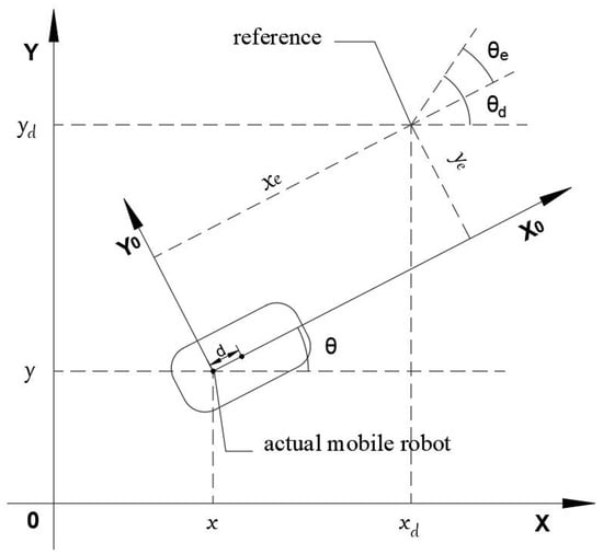
Figure 1.
Posture errors of the coordinate for NMR.
Since
its derivative can be written as
Since
its derivative can be written as
Since
its derivative can be written as
Then, the first derivative of can be written as
In this article, we consider the influence of d, which will affect the steering problem of the NMR. Therefore, Formula (9) is different from that in [30].
3. Main Results
As shown in Figure 2, the detail tracking control can be described in the next three subsections. To solve the problem of unknown slipping and skidding, Section 3.1 proposes predefined time observers to achieve accurate disturbance estimation for , , and . Then, Section 3.2 proposes predefined time active controllers to achieve the high-precision tracking performance of the NMR. To solve the holonomic tracking problem of the NMR, the tracking trajectory is redesigned in Section 3.3 to realize the accurate holonomic tracking of the NMR.

Figure 2.
Block diagram of the proposed algorithm.
3.1. Observer Design
To design a control scheme for the disturbance estimation of unknown slipping and skidding, the following assumption is required:
Assumption 1.
For an NMR, the disturbances ,, and μ, and their first derivatives are bounded.
where with and are the unknown positive constants, which define the upper bound of the disturbance.
Lemma 3.
Considering the derivation of , and supposing that Assumption 1 holds, the disturbance observer of is desinged as
where and are the designed gains. is the parameter predefined in advance, and
is the auxiliary design variable of the predefined time observer, which is designed as
where is the auxiliary design variable of the fixed time observer, and is the estimation of . Then, the observer (10) can achieve convergence in predefined time .
Proof.
For , we have
Choose a Lyapunov function candidate as
Its derivative along (12) satisfies
According to Lemma 2, it can be concluded that ; then, we have
Then,
According to Lemma 1, it can be concluded that , i.e., and when , where
Based on (11), we have and when . The proof is completed. □
Now, based on the results of Lemma 3, we continue to design predefined time observers to estimate the unknown disturbances and within a predefined time . Since after , we have
It can be seen from the above formulas that disturbance only affects Formula (15), and disturbance only affects Formula (14), so they can be estimated separately.
Lemma 4.
Considering (15), supposing that Assumption 1 and Theorem 3 hold; the disturbance observer of μ is then designed as
where is the parameter predefined in advance. is the auxiliary design variable of the predefined time observer, which is designed as
where is the auxiliary design variable of the fixed time observer, and is the estimation of . Then, the observer (16) can achieve convergence in predefined time .
Proof.
For , we have
Choose a Lyapunov function candidate as
Its derivative along (18) satisfies
According to Lemma 2, it can be concluded that ; then, we have
Then,
According to Lemma 1, it can be concluded that , i.e., and when , where
Based on (17), we have and when . The proof is completed. □
Next, we continue to design a predefined time observer to estimate .
Lemma 5.
Considering (14), supposing that Assumption 1 and Lemma 3 hold, the disturbance observer of is designed as
where is the auxiliary design variable of the predefined time observer, which is designed as
where is the auxiliary design variable of the fixed time observer, and is the estimation of . Then, the observer (20) can achieve convergence in predefined time .
Proof.
For , we have
Choose a Lyapunov function candidate as
Its derivative along (22) satisfies
According to Lemma 2, it can be concluded that ; then, we have
Then,
According to Lemma 1, it can be concluded that , i.e., and when . Based on (21), we have and when . The proof is completed. □
Remark 2.
From Lemma 3, the disturbance can be accurately estimated by within the predefined time . From the observation formula of disturbance and the observation formula of disturbance μ, they both depend on disturbance , and they are independent of each other, which can be estimated simultaneously. From Lemma 4 and 5, both disturbances and μ can be accurately estimated within the predefined time of .
Remark 3.
Mario et al. [33] solved the robust synchronization problem of a class of differential-drive mobile robots in distance and orientation by designing an active disturbance rejection controller (ADRC). In this article, the predefined time observers were used to track unknown slipping and skidding in real time, and the following controllers were designed on this basis, which could effectively avoid the impact of system disturbances on the robustness of the controllers.
3.2. Control Law Design
By relying on the estimation of the disturbances by observer (10), by observer (16), and by observer (20), the unknown slipping and skidding problem of system (9) was resolved. Then, the tracking problem of the system (6) needed to be solved, where the objective is for the NMR to track the tracking trajectory . Considering an NMR (6) with unknown slipping and skidding, the robust controller is designed as
where is the parameter predefined in advance. Then, the tracking error (8) has predefined time stability under the developed disturbance observers. Based on the design idea of backstepping, we consider the following subsystem
Theorem 1.
The tracking error can achieve convergence in predefined time under the angular velocity controller designed as (23), where the predefined time is described as
Proof.
Choose a Lyapunov function candidate as
Its derivative along (26) satisfies
According to Lemma 2, it can be concluded that , i.e., when , where
This proof is completed. □
Since after , then we have
and
Theorem 2.
There exists
Thus, system (29) is stable in predefined time, and the settling time is , which is described as
Proof.
We choose a Lyapunov function candidate as
Its derivative satisfies
According to Lemma 2, it can be concluded that , i.e., when , where
This proof is completed. □
To achieve the predefined time stability of , the sliding manifold method is adopted in this article. The sliding manifold is defined by
Its derivative can be written as
Theorem 3.
The tracking errors and can achieve convergence in predefined time using the velocity controller of a nonholonomic mobile robot designed as
Proof.
Choose a Lyapunov function candidate as
Its derivative along (32) satisfies
According to Lemma 2, it can be concluded that , i.e., when , where
This proof is completed. □
Remark 4.
A new type of ESO was established in [34] to estimate the states and the total disturbance of wheeled mobile robots. Then, a fixed time controller based on the above ESO was developed to achieve high-precision control performance. Compared with [34], the complex relationship between the system parameters and the settling time was transformed into a one-to-one correspondence between the settling time and the parameter (where ) in this article. By tuning , system (9) can be stabilized at different predefined time, which is simpler and more effective than the fixed time stability.
3.3. The Holonomic Tracking Problem of NMR
If , according to Theorem 2, it can be obtained that
Then,
One can obtain that
Then we have
If or , then and . In order to realize holonomic tracking of the NMR, we assume that and ; the new tracking trajectory is designed as follows:
Then,
In this article, modifying and to and can realize holonomic tracking of and .
Remark 5.
By redesigning the new tracking trajectory, this article changes the original situation that it is impossible to realize the holonomic tracking of the three states of an NMR with unknown slipping and skidding into the three states of an NMR.
4. Simulation
We applied the proposed predefined time observers and active predefined time controllers to an NMR. The simulation environment was MATLAB 2021B SIMULINK, and the step size was set to 0.001. Independent of the initial conditions, the desired tracking posture of the NMR is specified as
The desired posture was a circle with the radius of the circular trajectory . Then, the NMR could make a uniform circular motion. The desired forward velocity was given by . The desired angular velocity was given by .
According to Lemma 3, we can design the predefined time observer for as (10). The parameters of the observer were chosen as , , , , and . Similarly, we can design the observer for as in (16), and we can design the observer as in (20), where the parameters were chosen as and . The disturbances were set as , , and . The simulation results are given in Figure 3, Figure 4, Figure 5 and Figure 6. In Figure 3, under the conditions that the initial conditions were unknown, the disturbance estimation could achieve an accurate estimation of the disturbance before the different predefined time . Similarly, it can be seen from Figure 4 and Figure 5 that, even if the disturbance was not constant, the disturbance and could also be accurately estimated within the predefined time . It was proven that Lemmas 4 and 5 are effective.
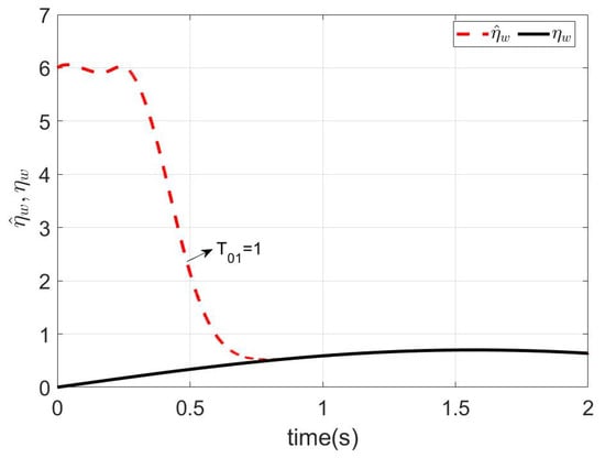
Figure 3.
Estimations of .
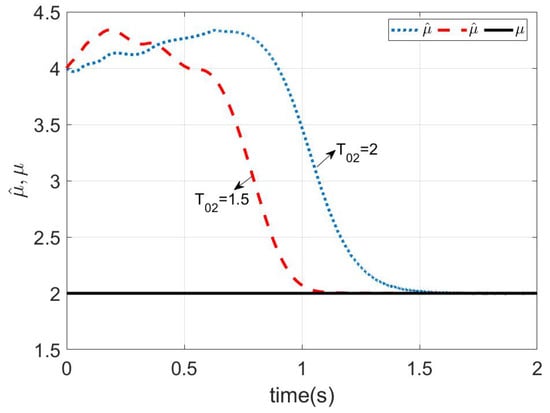
Figure 4.
Estimations of .
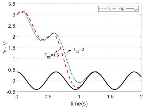
Figure 5.
Estimations of .
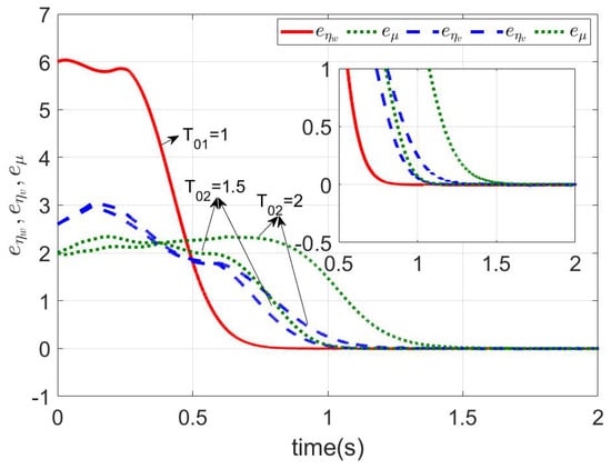
Figure 6.
Estimation errors of , , and .
Figure 6 shows the observer tracking error curves, namely, , , and . The disturbance of , , and all converged before the different predefined time. Next, the predefined time active controller was designed for the NMR. The parameters of the controllers (23) and (33) were chosen as , , and . Then, we could get the whole predefined time, which is shown as
The simulation results are shown in Figure 7 and Figure 8. As shown in Figure 7, it is worth noting that the angle error of tracking posture (37) converged to zero in . Similarly, the y-axis error of tracking posture (36) converged to zero. However, the x-axis error did not to converge to zero. The reason is that the mobile robot is nonholonomic. It is consistent with the results described in Remark 1. For the actual tracking trajectory shown in Figure 8, the NMR could not fully track the given tracking trajectory. For the predefined time , the simulation results are shown in Figure 9. It can be seen that the results are the same as in Figure 7, except that the convergence time was changed. The method proposed in this article could simply achieve a change in the system convergence time by changing the predefined time parameter . In order to realize holonomic tracking, we design the tracking trajectory as
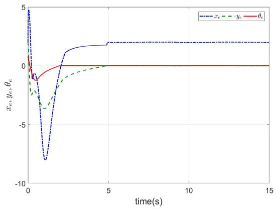
Figure 7.
The tracking errors of (35)–(37) with .
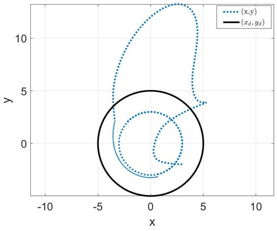
Figure 8.
The tracking trajectories of (35)–(37).
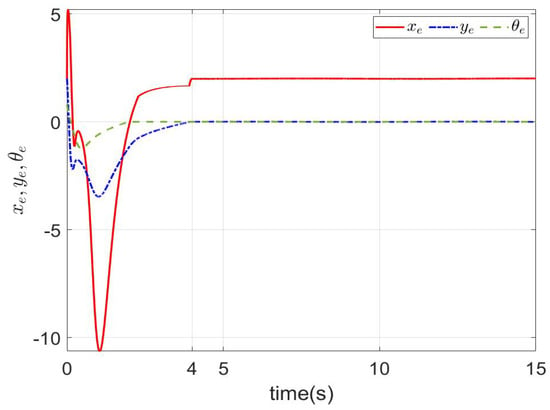
Figure 9.
The tracking errors of (35)–(37) with .
The simulation results are shown in Figure 10 and Figure 11. The tracking error is shown in Figure 10. As shown in Figure 10, it is worth noting that the angle error of tracking trajectory (40) converged to zero in . Similarly, the x-axis and y-axis errors of tracking postures (38) and (39) converged to zero in , respectively. It shows that, by modifying the tracking trajectory, the pseudo-full drive control of the nonholonomic system can be realized. The tracking curve is shown in Figure 11. The NMR could fully track the given signal. For the predefined time , the simulation results are shown in Figure 12. It can be seen that the results are the same as Figure 10, except that the convergence time was changed. Similarly, the method proposed in this article could simply achieve a change in the system convergence time by changing the predefined time parameter .
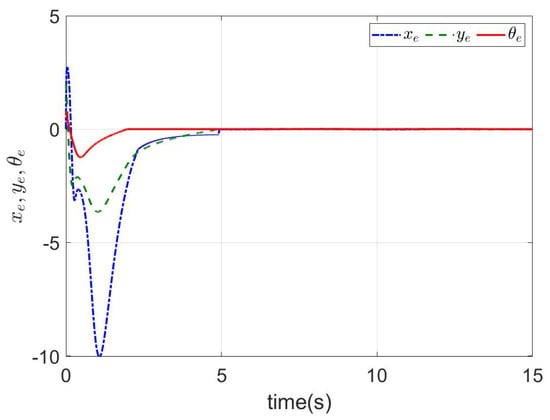
Figure 10.
The tracking errors of (38)–(40) with .
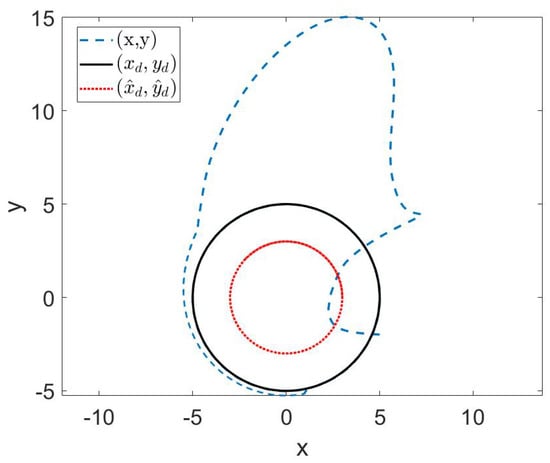
Figure 11.
The tracking trajectories of (38)–(40).
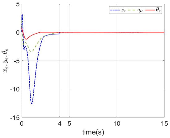
Figure 12.
The tracking errors of (38)–(40) with .
Remark 6.
The simulation results show that the proposed method is effective and feasible. The predefined time controllers designed in this article for an NMR did not consider the input saturation, so it could be stable within predefined time, and its convergence time was adjustable. Because of the input saturation of the actual NMR, the process of designing the predefined time controller under the condition of input saturation is the future work to do. This article assumes that the measurement data is accurate, but the sensor data of the actual NMR is uncertain, so it is necessary to consider the accuracy of the measurement data when the proposed method is applied to the actual environment.
Remark 7.
As shown in Figure 10, , , and all tended to zero within predefined time, thus indicating that the redesigned tracking trajectory could realize fast and accurate tracking of all the states of x, y, and θ of the NMR. Thus, the distance error () and the orientation error () also tended to zero in predefined time.
5. Conclusions
This article proposed a framework to solve the fast path tracking problem for an NMR with unknown slipping and skidding. Based on predefined time stability, predefined time observers were designed to accurately estimate the unknown slipping and skidding. Then, the trajectory tracking problem of NMR was solved by predefined time active controllers via backstepping design. Based on the simulation results, the designed predefined time observers could not only accurately estimate , , and , but also the settling time of the observer could be adjusted according to the actual situation. The designed predefined time controllers could realize fast and accurate tracking of the given trajectory. The redesigned new tracking trajectory could achieve full tracking of all states of the NMR. The proposed solution can be easily expanded for other types of tracking systems. In the upcoming research, we will focus on the following directions.
- (1)
- The model parameters used in this article are ideal without practical errors, while the parameters involve uncertainty in the actual NMR. In future work, the uncertainty of model parameters will be considered, and it is hoped that other schemes can be combined to achieve accurate estimation of the model of an NMR.
- (2)
- We will continue to apply the method of predefined time observer and predefined time controller in this article to an actual NMR for verification.
- (3)
- Compared with classical controllers such as the PID controller, the proposed scheme is more complex, theoretically requires more computation, and occupies more CPU resources. In practical applications, algorithm improvements should be made to adapt to the configuration of the actual hardware environment of an actual NMR, thus reducing the complexity and computational complexity of the algorithm and improving its computing speed.
Author Contributions
Conceptualization, L.L.; Methodology, L.L.; Software, Z.X. and J.Z.; Writing—original draft, L.L.; Writing—review & editing, Z.X.; Supervision, L.L.; Funding acquisition, J.Z. All authors have read and agreed to the published version of the manuscript.
Funding
This research was funded by the Startup Research Project of Jimei University (No. ZQ2022002), the Natural Science Foundation of Fujian Province, China (No. 2019J05024), the Fujian Province Young and Middle-aged Teacher Education Research Project (No. JAT220182), the Xiamen Ocean and Fishery Development Special Fund Project (No. 21CZB013HJ15), and the Xiamen Key Laboratory of Marine Intelligent Terminal R&D and Application (No. B18208), Jimei University (No. ZP2020042).
Data Availability Statement
No data have been used in the manuscript.
Acknowledgments
The authors are very thankful to all the anonymous referees for their very useful and constructive comments in order to improve the paper.
Conflicts of Interest
The authors declares no conflict of interest.
References
- Huang, B.; Yang, C.; Meng, Z.; Chen, F.; Ren, W. Distributed Nonlinear Placement for Multicluster Systems: A Time-Varying Nash Equilibrium-Seeking Approach. IEEE Trans. Cybern. 2021, 52, 11614–11623. [Google Scholar] [CrossRef] [PubMed]
- Wu, L.; Wang, D.; Zhang, C.; Mohammadzadeh, A. Chaotic Synchronization in Mobile Robots. Mathematics 2022, 10, 4568. [Google Scholar] [CrossRef]
- Ning, B.; Han, Q.L.; Lu, Q. Fixed-Time Leader-Following Consensus for Multiple Wheeled Mobile Robots. IEEE Trans. Cybern. 2019, 50, 4381–4392. [Google Scholar] [CrossRef] [PubMed]
- Wang, D.; Low, C. Modeling and Analysis of Skidding and Slipping in Wheeled Mobile Robots: Control Design Perspective. IEEE Trans. Robot. 2008, 24, 676–687. [Google Scholar] [CrossRef]
- Yo, S.J. Adaptive tracking control for a class of wheeled mobile robots with unknown skidding and slipping. IET Control Theory Appl. 2010, 4, 2109–2119. [Google Scholar] [CrossRef]
- Shang, S.; Xin, Y.; Khoo, S. Robust finite-time tracking control of nonholonomic mobile robots without velocity measurements. Int. J. Control 2016, 89, 411–423. [Google Scholar]
- Zhu, Y.; Huang, Y.; Su, J.; Pu, C. Active Disturbance Rejection Control for Wheeled Mobile Robots with Parametric Uncertainties. IFAC-PapersOnLine 2020, 53, 1355–1360. [Google Scholar] [CrossRef]
- Hua, G.; Wang, F.; Zhang, J.; Alattas, K.A.; Mohammadzadeh, A.; The Vu, M. A New Type-3 Fuzzy Predictive Approach for Mobile Robots. Mathematics 2022, 10, 3186. [Google Scholar] [CrossRef]
- Bregon, A.; Alonso-Gonzalez, C.J.; Pulido, B. Integration of Simulation and State Observers for Online Fault Detection of Nonlinear Continuous Systems. IEEE Trans. Syst. Man Cybern. Syst. 2014, 44, 1553–1568. [Google Scholar] [CrossRef]
- Dhouha, K.; Hamdi, G.; Hajjaji, E.; Mohamed, C. Adaptive Observer and Fault Tolerant Control for Takagi-Sugeno Descriptor Nonlinear Systems with Sensor and Actuator Faults. Int. J. Control. Autom. Syst. 2018, 16, 972–982. [Google Scholar]
- Xu, B. Disturbance Observer-Based Dynamic Surface Control of Transport Aircraft with Continuous Heavy Cargo Airdrop. IEEE Trans. Syst. Man Cybern. Syst. 2017, 47, 161–170. [Google Scholar] [CrossRef]
- Lopez-Ramirez, F.; Polyakov, A.; Efimov, D.; Perruquetti, W. Finite-Time and Fixed-Time Observer Design: Implicit Lyapunov Function Approach. Automatica 2018, 87, 52–60. [Google Scholar] [CrossRef]
- Matei, A.; Precup, S.A.; Circa, D.; Gellert, A.; Zamfirescu, C.B. Estimating Travel Time for Autonomous Mobile Robots through Long Short-Term Memory. Mathematics 2023, 11, 1723. [Google Scholar] [CrossRef]
- Aoustin, Y.; Chevallereau, C.; Orlov, Y. Finite time stabilization of a perturbed double integrator—Part II: Applications to bipedal locomotion. In Proceedings of the 49th IEEE Conference on Decision and Control (CDC), Atlanta, GA, USA, 15–17 December 2010. [Google Scholar]
- Khalil, H.; Praly, L. High-gain observers in nonlinear feedback control. Int. J. Robust Nonlinear Control 2014, 24, 991–992. [Google Scholar] [CrossRef]
- Angulo, M.; Moreno, J.; Leonid, F. Robust exact uniformly convergent arbitrary order differentiator. Automatica 2013, 49, 2489–2495. [Google Scholar] [CrossRef]
- Perruquetti, W.; Floquet, T.; Moulay, E. Finite-Time Observers: Application to Secure Communication. IEEE Trans. Autom. Control 2008, 53, 356–360. [Google Scholar] [CrossRef]
- Wang, J.; Dong, H.; Chen, F.; Vu, M.T.; Shakibjoo, A.D.; Mohammadzadeh, A. Formation Control of Non-Holonomic Mobile Robots: Predictive Data-Driven Fuzzy Compensator. Mathematics 2023, 11, 1804. [Google Scholar] [CrossRef]
- Zhao, H.; Wu, X.; Xie, Y.; Du, Y.; Zhang, Z.; Li, Y. Rotation matrix-based finite-time attitude synchronization control for flexible spacecrafts with unknown inertial parameters and actuator faults. ISA Trans. 2021, 128, 276–289. [Google Scholar] [CrossRef]
- Lv, W.; Kang, Y.; Zhao, Y.; Wu, Y.; Zheng, W. A Novel Inertial-Visual Heading Determination System for Wheeled Mobile Robots. IEEE Trans. Control Syst. Technol. 2021, 29, 1758–1765. [Google Scholar] [CrossRef]
- Li, Z.; Zhao, Y.; Yan, H.; Wang, M.; Zeng, L. Prescribed-time zero-error active disturbance rejection control for uncertain wheeled mobile robots subject to skidding and slipping. Int. J. Syst. Sci. 2023, 54, 1313–1329. [Google Scholar] [CrossRef]
- Chen, Y.H.; Chen, Y.Y. Trajectory Tracking Design for a Swarm of Autonomous Mobile Robots: A Nonlinear Adaptive Optimal Approach. Mathematics 2022, 10, 3901. [Google Scholar] [CrossRef]
- Bayat, F.; Mobayen, S.; Javadi, S. Finite-time tracking control of nth-order chained-form non-holonomic systems in the presence of disturbances. ISA Trans. 2016, 63, 78–83. [Google Scholar] [CrossRef] [PubMed]
- Zhang, Y.; Liu, G.; Luo, B. Finite-time cascaded tracking control approach for mobile robots. Inf. Sci. 2014, 284, 31–43. [Google Scholar] [CrossRef]
- Wei, H.; Yang, Y.; Hua, C. Fixed-time Tracking Control Approach Design for Nonholonomic Mobile Robot. In Proceedings of the Control Conference 2016, Aalborg, Denmark, 29 June–1 July 2016. [Google Scholar]
- Defoort, M.; Zuo, Z.; Djemai, M.; Demesure, G.; Polyakov, A. Fixed-time stabilization and consensus of nonholonomic systems. IET Control Theory Appl. 2016, 10, 2497–2505. [Google Scholar] [CrossRef]
- Ning, B.; Han, Q.L. Prescribed Finite-Time Consensus Tracking for Multi-Agent Systems with Nonholonomic Chained-Form Dynamics. IEEE Trans. Autom. Control 2019, 64, 1686–1693. [Google Scholar] [CrossRef]
- Zhao, T.; Ding, Z. Distributed Finite-Time Optimal Resource Management for Microgrids Based on Multi-Agent Framework. IEEE Trans. Ind. Electron. 2018, 65, 6571–6580. [Google Scholar] [CrossRef]
- Lin, L.; Wu, P.; He, B.; Chen, Y.; Zheng, J.; Peng, X. The sliding mode control approach design for nonholonomic mobile robots based on non-negative piecewise predefined-time control law. IET Control Theory Appl. 2021, 15, 1286–1296. [Google Scholar] [CrossRef]
- Chen, M. Disturbance Attenuation Tracking Control for Wheeled Mobile Robots with Skidding and Slipping. IEEE Trans. Ind. Electron. 2016, 64, 3359–3368. [Google Scholar] [CrossRef]
- Shao, X.; Tian, B.; Yang, W. Fixed-time trajectory following for quadrotors via output feedback. ISA Trans. 2021, 110, 213–224. [Google Scholar] [CrossRef]
- Lin, L. Predefined-time synchronization of 5D Hindmarsh Rose neuron networks via backstepping design and application in secure communication. Nonlinear Anal. Model. Control 2022, 27, 630–649. [Google Scholar] [CrossRef]
- Ramírez-Neria, M.; González-Sierra, J.; Luviano-Juárez, A.; Lozada-Castillo, N.; Madonski, R. Active Disturbance Rejection Strategy for Distance and Formation Angle Decentralized Control in Differential-Drive Mobile Robots. Mathematics 2022, 10, 3865. [Google Scholar] [CrossRef]
- Chang, S.; Wang, Y.; Zuo, Z. Fixed-Time Active Disturbance Rejection Control and Its Application to Wheeled Mobile Robots. IEEE Trans. Syst. Man Cybern. Syst. 2021, 51, 7120–7130. [Google Scholar] [CrossRef]
Disclaimer/Publisher’s Note: The statements, opinions and data contained in all publications are solely those of the individual author(s) and contributor(s) and not of MDPI and/or the editor(s). MDPI and/or the editor(s) disclaim responsibility for any injury to people or property resulting from any ideas, methods, instructions or products referred to in the content. |
© 2023 by the authors. Licensee MDPI, Basel, Switzerland. This article is an open access article distributed under the terms and conditions of the Creative Commons Attribution (CC BY) license (https://creativecommons.org/licenses/by/4.0/).