Separation and Calibration Method of Structural Parameters of 6R Tandem Robotic Arm Based on Binocular Vision
Abstract
1. Introduction
2. Methods
2.1. Geometric Error Identification
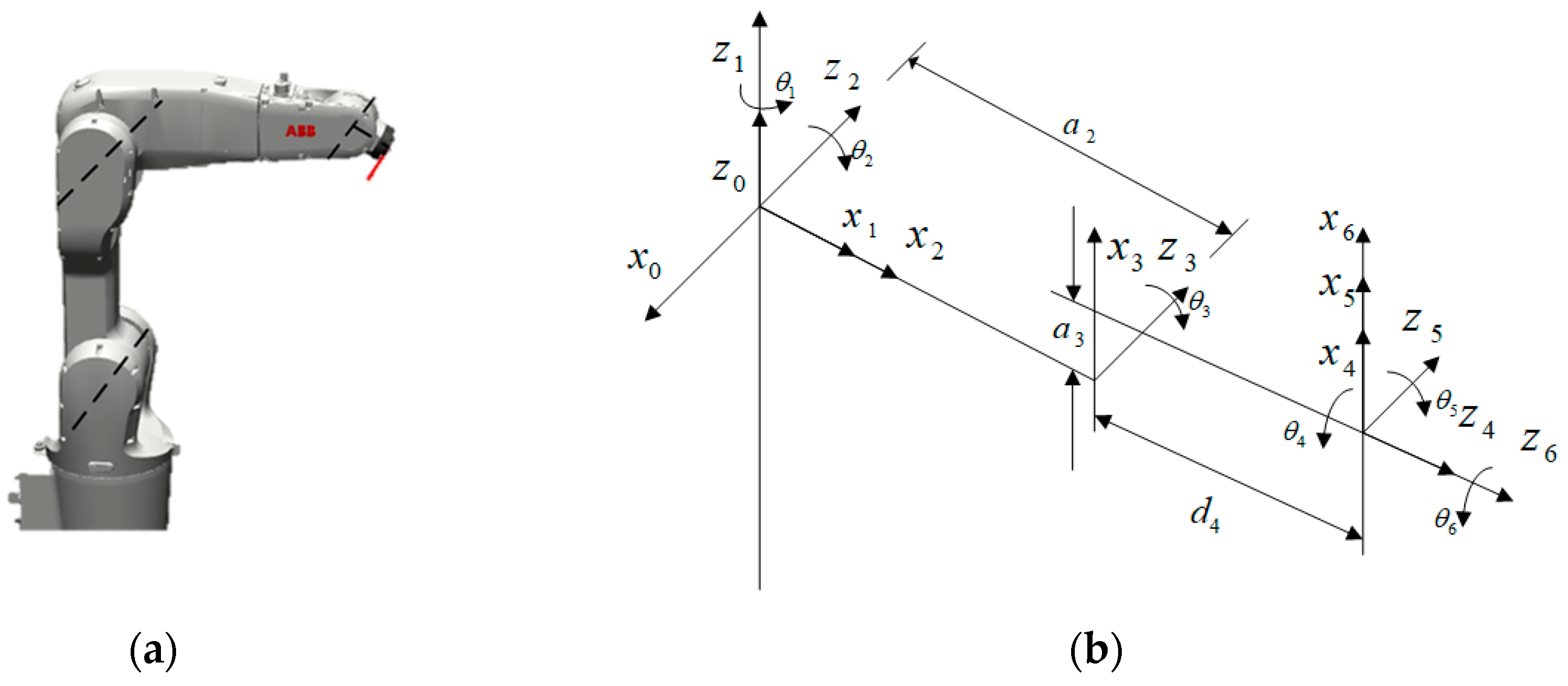
2.1.1. Robotic Arm Kinematics Model
2.1.2. Error Mapping Model
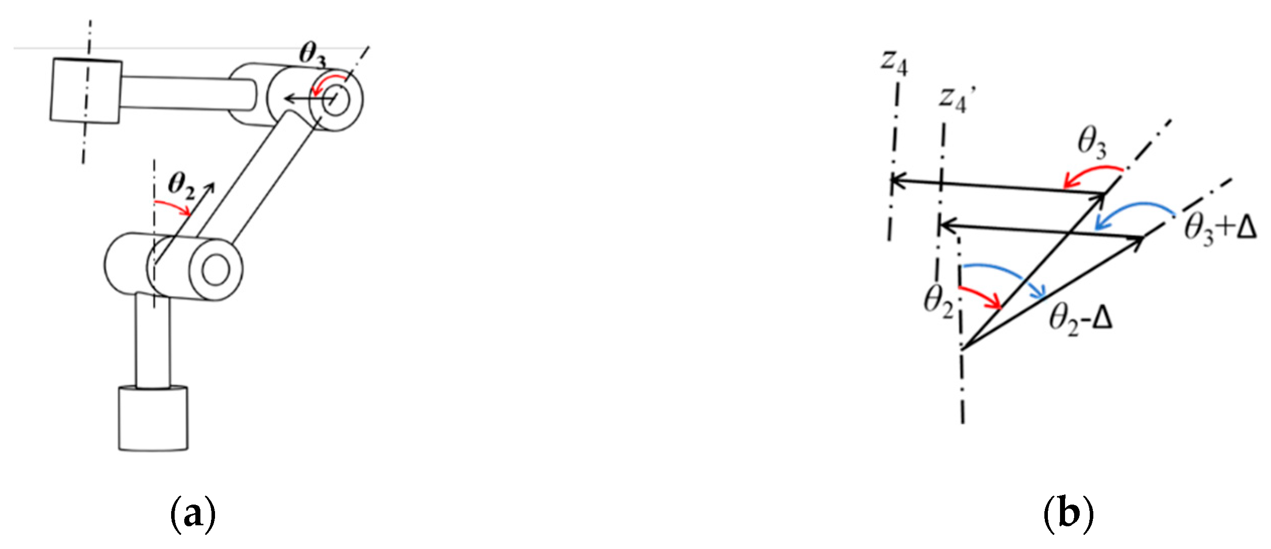
2.1.3. Joint Parameter Error Separation
2.1.4. Angel Constraints and Distance Constraints
2.1.5. Identification Equation Optimization
2.2. Pose Measurement Based on Binocular Vision
2.2.1. The Principle of Binocular Vision Stereo Measurement
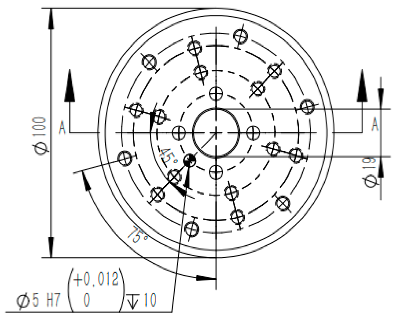
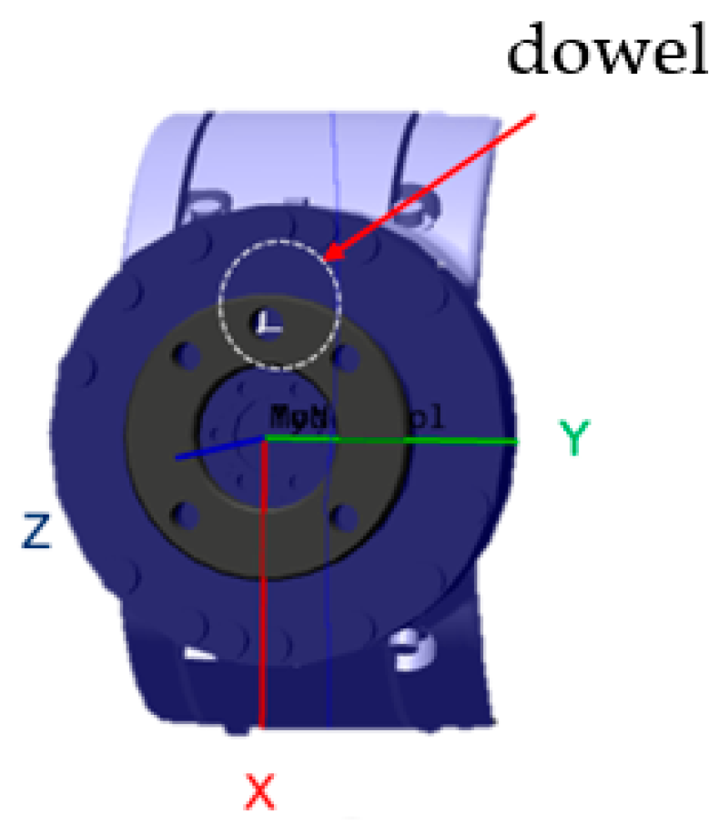
2.2.2. Setting of Key Coordinate Systems and Measurement Markers
2.3. Simulation Model Design
- (1)
- For the theoretical kinematics model, 50 groups of joint angle data of the beginning and end of the posture movement were obtained. Half of each joint’s rotation angle data are used as the calibration set, and the other half are used as the compensation set. Denote the theoretical moving distance and theoretical motion posture obtained by calibrating the joint rotation angle of the set as .
- (2)
- Set the error value of each parameter, input the error value into the simulation model, and input the beginning and end joint rotation angle into the kinematic model with error to obtain the actual moving distance and motion posture. Record as .
- (3)
- Take and as input, bring into the identification equation established above, and calculate the joint parameter error in combination with the established angle constraints.
- (4)
- Compensate the calculated joint parameter errors into the theoretical kinematics model, input the beginning and end data of the joint rotation angle of the compensation set into the simulation model, and calculate the posture motion after compensation.
- (5)
- Compare the posture motion after compensation with the posture motion before compensation and determine the motion accuracy of the tandem robotic arm after compensation.
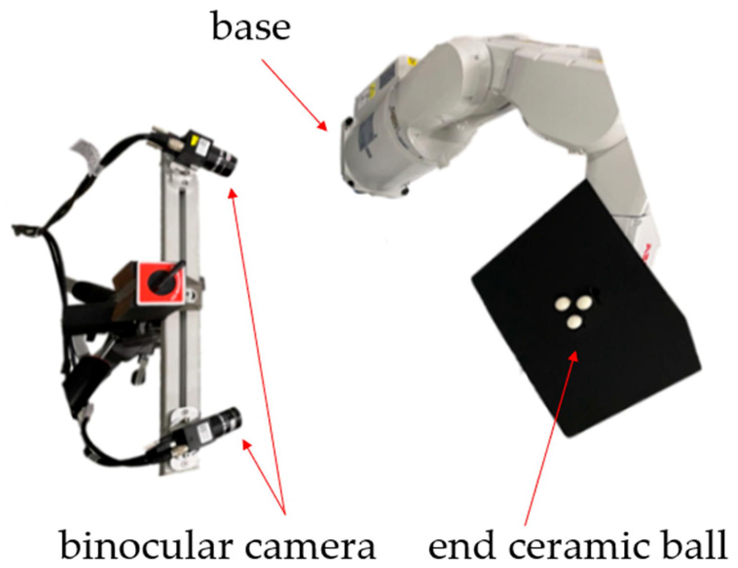
2.4. Tandem Robotic Arm Entity Experiment Design
- (1)
- Given different end poses, bring in an error-free theoretical kinematics positive solution model, and obtain the beginning and end rotation angles of each joint motion.
- (2)
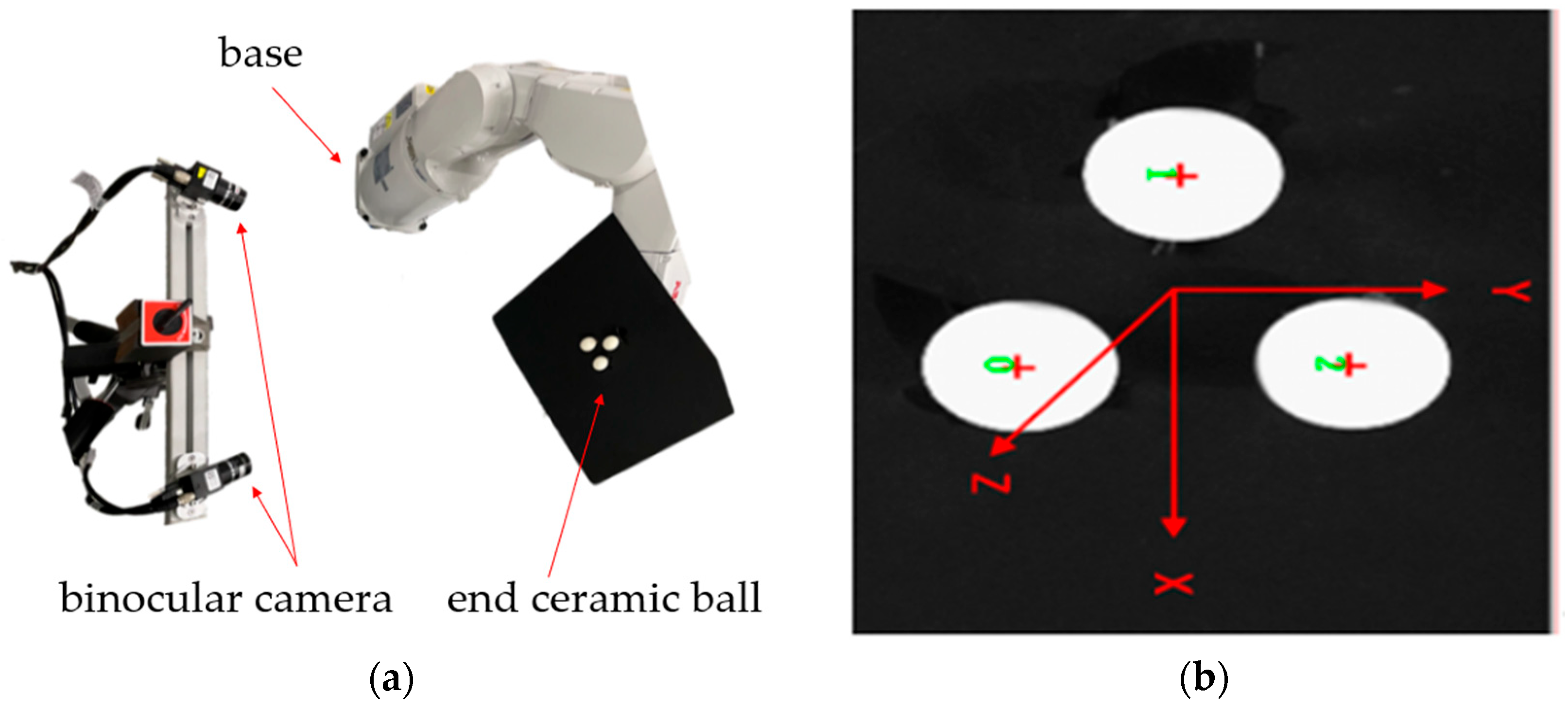
- Control the movement of the tandem robotic arm to the beginning and end of each joint movement, and the binocular camera measures the actual movement distance and movement posture.
- (3)
- Execute the calibration procedure to obtain the joint parameter error of the tandem robotic arm and compensate the joint parameter error into the theoretical kinematics model of the tandem robotic arm and obtain the actual motion end angle of each joint through the actual inverse solution.
- (4)
- Control the movement of the tandem robotic arm to the actual movement end angle of each joint, and the binocular camera measures the movement distance and movement posture of the end after compensation.
- (5)
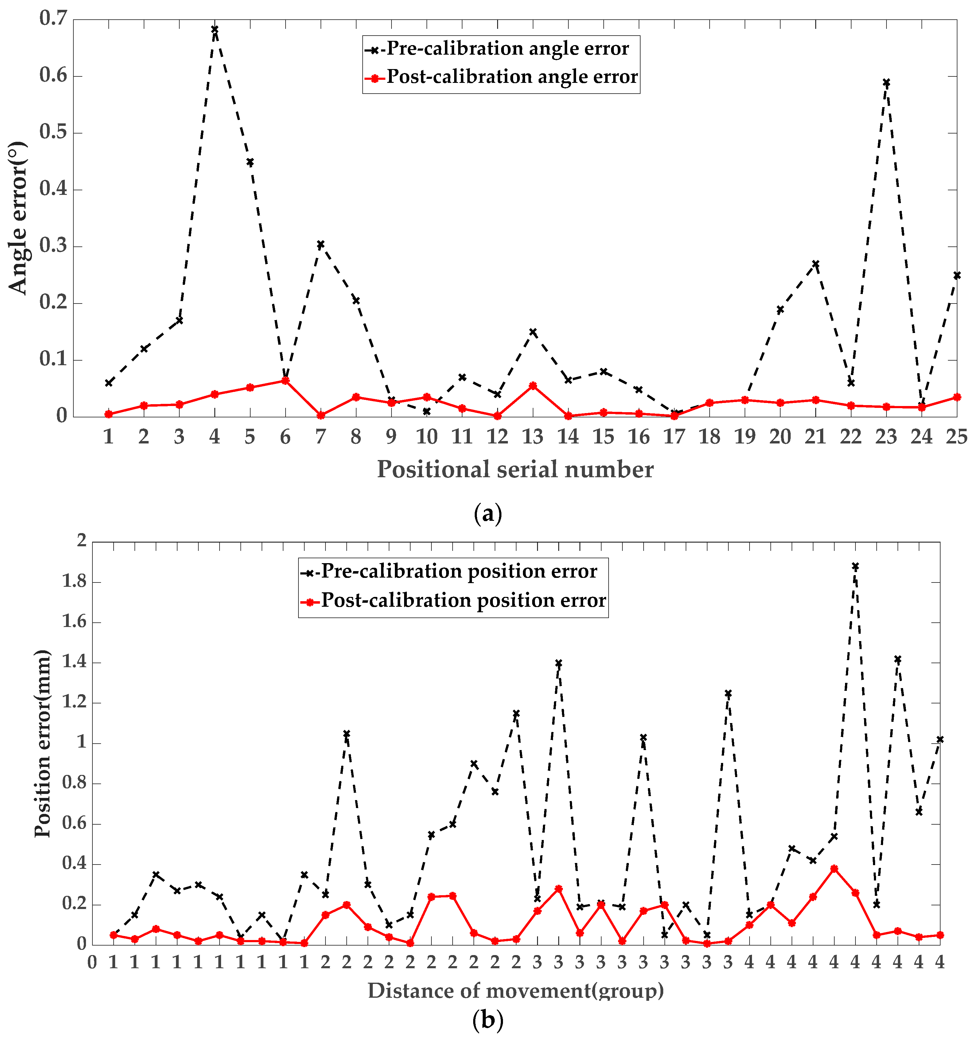
- Compare the end pose error values before and after compensation.
- (1)
- Knowing each joint parameter P and the theoretical pose of the tandem robotic arm in the Cartesian coordinate system, the initial joint rotation angle is obtained from the theoretical inverse solution in Section 2.1.1.
- (2)
- Bring into the kinematic model with error to obtain the actual pose of the tandem robotic arm.
- (3)
- Calculate the amount of change in the end pose caused by the joint angle increasing by one step and obtain the mapping function between the joint angle increasing by one step and the end pose transformation.
- (4)
- Calculate the change amount of the joint rotation angle through the difference between the actual pose and the theoretical pose and bring it into the mapping function in step (3) to obtain the increase value of the joint rotation angle.
- (5)
- Bring the obtained joint angle into the kinematics model with error, get a set of poses compare the sum, if the calculation accuracy is satisfied, output the actual pose of each joint angle; if not, put as the initial pose, repeat steps (3) to (5) until the calculation accuracy is satisfied.
3. Results
3.1. Simulation Model Results
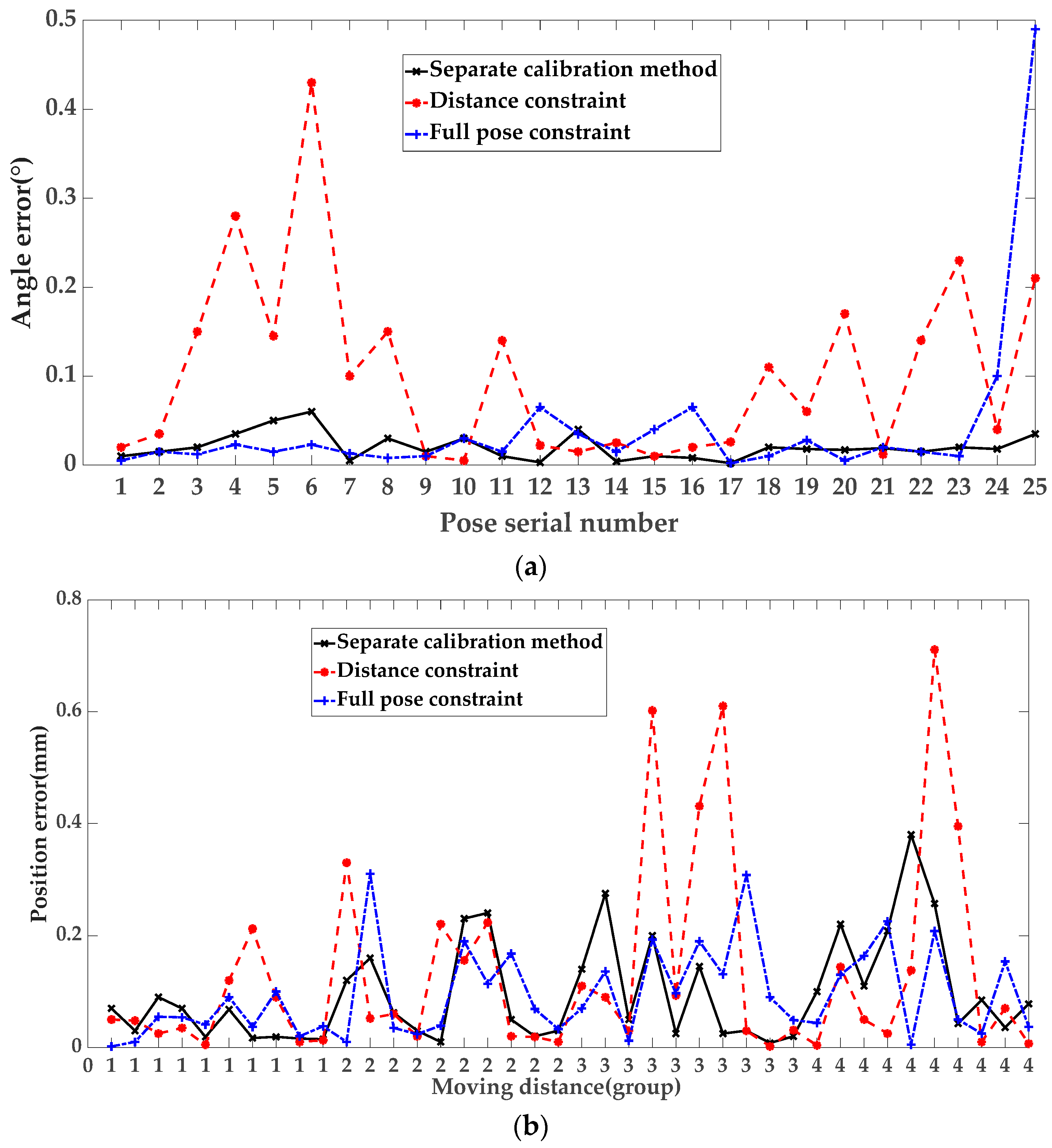
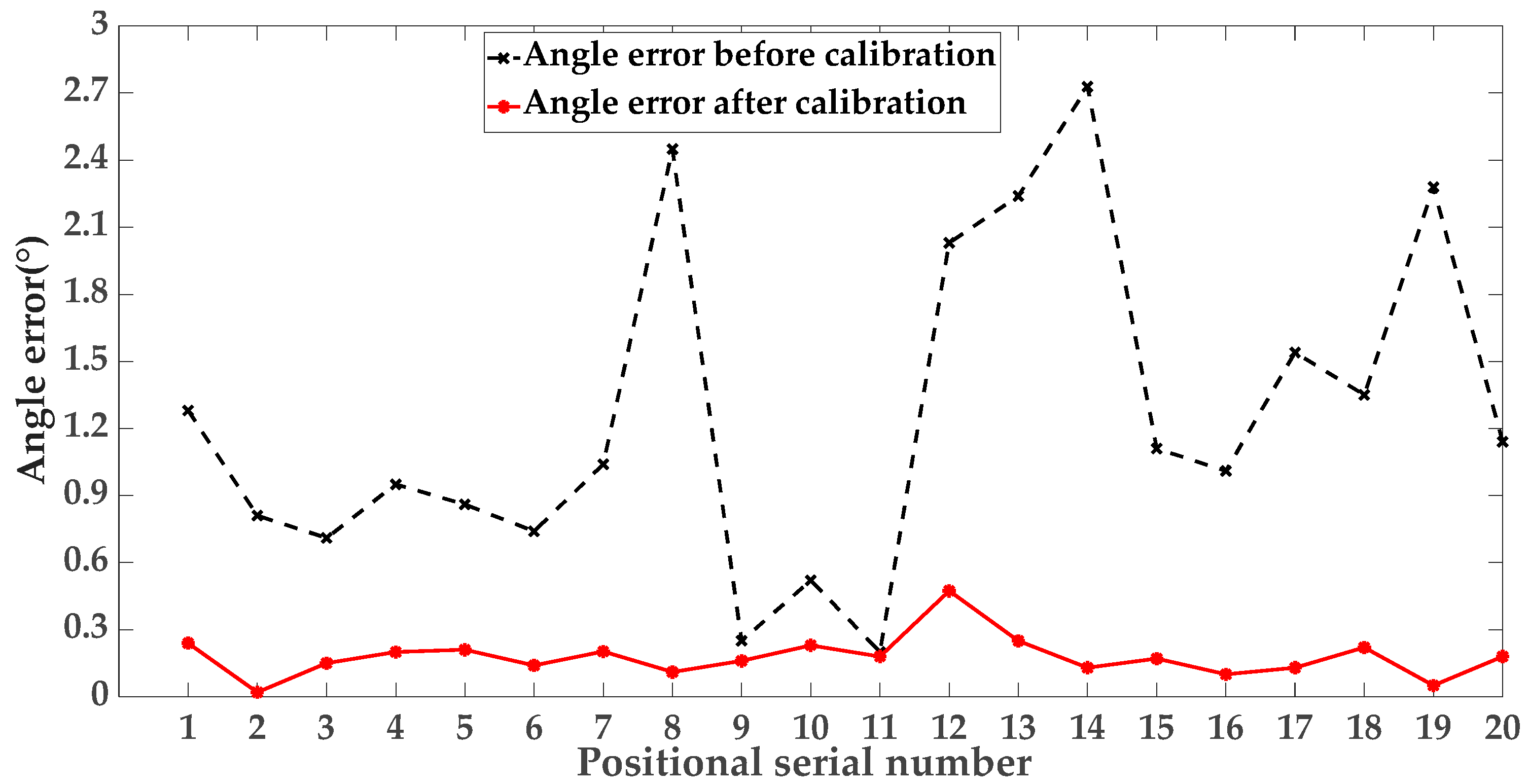
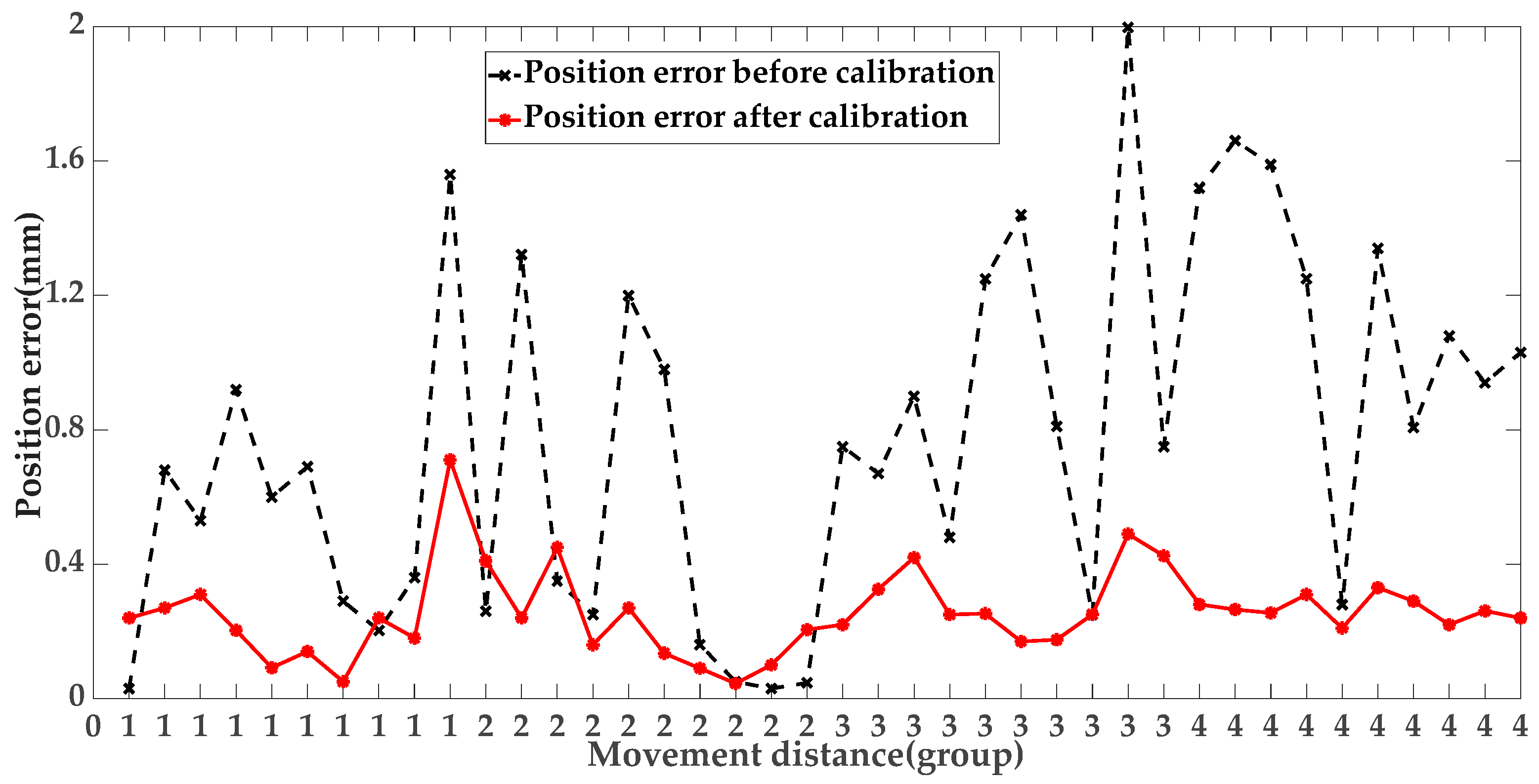
3.2. Tandem Robotic Arm Entity Experiment Results
4. Conclusions
Author Contributions
Funding
Data Availability Statement
Acknowledgments
Conflicts of Interest
References
- Joubair, A.; Bonev, I.A. Kinematic calibration of a six-axis serial robot using distance and sphere constraints. Int. J. Adv. Manuf. Technol. 2015, 77, 515–523. [Google Scholar] [CrossRef]
- Ding, X.; Zhou, L.; Zhou, J. Pose error analysis of robot in three dimension. J. Beijing Univ. Aeronaut. Astronaut. 2009, 35, 241–245. [Google Scholar]
- Nubiola, A.; Bonev, I.A. Absolute calibration of an ABB IRB 1600 robot using a laser tracker. Robot. Comput.-Integr. Manuf. 2013, 29, 236–245. [Google Scholar] [CrossRef]
- Gao, G.; Sun, G.; Na, J. Structural Parameter Identification for 6 Dof Industrial Robots. Mech. Syst. Signal. Pr. 2018, 113, 145–155. [Google Scholar] [CrossRef]
- Schröer, K.; Albright, S.L.; Grethlein, M. Complete, Minimal and model-continuous kinematic models for robot calibration. Robot. Cim.-Int. Manuf. 1997, 13, 73–85. [Google Scholar] [CrossRef]
- Samad, A.H.; Hayati, S. Robot arm geometric link parameter estimation. In Proceedings of the IEEE Conference on Decision & Control, San Antonio, TX, USA, 14–16 December 1983. [Google Scholar]
- Veitschegger, W.; Wu, C.H. A method for calibration and compensation of robot kinematic errors. In Proceedings of the IEEE ICRA, Raleigh, NC, USA, 31 March–3 April 1987. [Google Scholar]
- Stone, H.W.; Sanderson, A.C. Statistical performance evaluation of the S-model arm signature identification technique. In Proceedings of the IEEE ICRA, Philadelphia, PA, USA, 24–29 April 1988. [Google Scholar]
- Zhuang, H.; Roth, Z.S.; Hamano, F. A complete and parametrically continuous kinematic model for robot manipulators. In Proceedings of the IEEE ICRA, Cincinnati, OH, USA, 13–18 May 1990. [Google Scholar]
- Lv, L.; Li, X.H.; Fei, S.X. Kinematics Modeling and Analysis of 6R Manipulator Based on Screw Method. J. Chifeng Univ. 2019, 35, 53–55. [Google Scholar]
- Chen, I.; Yang, G.; Tan, C.T. Local Poe Model for Robot Kinematic Calibration. Mech. Mach. Theory 2001, 36, 1215–1239. [Google Scholar] [CrossRef]
- Yin, J.; Gao, Y. Pose Accuracy Calibration of a Serial Five DOF Robot. Energy Procedia 2012, 14, 977–982. [Google Scholar] [CrossRef]
- Xie, Z.; Zong, P.; Yao, P.; Ren, P. Calibration of 6-DOF industrial robots based on line structured light. Optik 2019, 183, 1166–1178. [Google Scholar] [CrossRef]
- Wang, F. Research on the monitoring method of robotic arm end pose based on image visual features. Mach. Des. Manuf. 2023, 1–5. (In Chinese) [Google Scholar]
- Yang, J.; Wang, D.; Fan, B.; Dong, D.; Zhou, W. Online Absolute Pose Compensation and Steering Control of Industrial Robot Based on Six Degrees of Freedom Laser Measurement. Opt. Eng. 2017, 56, 34111. [Google Scholar] [CrossRef]
- Lgnani, G.; Tiboni, M. Optimal design and application of a low-cost wire-sensor system for the kinematic calibration of industrial manipulators. Mech. Mach. Theory 2014, 73, 25–48. [Google Scholar] [CrossRef]
- Olarra, A.; Axinte, D.; Kortaberria, G. Geometrical calibration and uncertainty estimation methodology for a novel self-propelled miniature robotic machine tool. Robot. Cim.-Int. Manuf. 2018, 49, 204–214. [Google Scholar] [CrossRef]
- Jiang, Z.X.; Qin, P.J.; Su, R. High precision visual monitoring of robotic arm pose based on deep learning. Modul. Mach. Tools Autom. Manuf. Tech. 2022, 11, 138–142. [Google Scholar]
- Lu, Y.; Shen, T.X.; Luo, Z. Calibration of kinematics parameters of industrial robot based on linear structured light Sensor. Acta Metrol. Sin. 2021, 42, 66–71. [Google Scholar]
- Luo, Z.J.; Sun, S.J.; Mei, J.P. Research on robot calibration application based on wire displacement sensor. Aeronaut. Manuf. Technol. 2017, 9, 43–49. [Google Scholar]
- Balanji, H.M.; Turgut, A.E.; Tunc, L.T. A novel vision-based calibration framework for industrial robotic manipulators. Robot. Cim.-Int. Manuf. 2022, 73, 102248. [Google Scholar] [CrossRef]
- Rozlivek, J.; Rustler, L.; Stepanova, K. Multisensorial robot calibration framework and toolbox. In Proceedings of the IEEE-RAS, Munich, Germany, 15–17 November 2021. [Google Scholar]
- Li, Z.B.; Li, S.; Luo, X. Using Quadratic Interpolated Beetle Antennae Search to Enhance Robot Arm Calibration Accuracy. In Proceedings of the IEEE-RAL, Xishuangbanna, China, 5–9 December 2022. [Google Scholar]
- Wang, X.L.; An, L.X.; Zhang, H.Z. Error analysis and simulation research of manipulator based on calibration method of kinematics parameters. Mech. Electr. Eng. 2019, 36, 109–116. [Google Scholar]
- Urrea, C.; Pascal, J. Design, simulation, comparison and evaluation of parameter identification methods for an industrial robot. Comput. Electr. Eng. 2018, 67, 791–806. [Google Scholar] [CrossRef]
- Chen, X.; Zhang, Q.; Sun, Y. Non-kinematic Calibration of Industrial Robots Using a Rigid–flexible Coupling Error Model and a Full Pose Measurement Method. Robot. Cim.-Int. Manuf. 2019, 57, 46–58. [Google Scholar] [CrossRef]
- Dolinsky, J.U.; Jenkinson, I.D.; Colquhoun, G.J. Application of Genetic Programming to the Calibration of Industrial Robots. Comput. Ind. 2007, 58, 255–264. [Google Scholar] [CrossRef]
- Lattanzi, L.; Cristalli, C.; Massa, D. Geometrical calibration of a 6-axis robotic arm for high accuracy manufacturing task. Int. J. Adv. Manuf. Technol. 2020, 111, 1813–1829. [Google Scholar] [CrossRef]
- Shi, Y.Q.; Li, K.F.; Lu, R.S. Kinematics parameter identification of industrial robot based on binocular vision. Laser Optoelectron. Prog. 2022, 1–13. (In Chinese) [Google Scholar]
- Xing, Y.L.; Li, L. A method for calibration of mechanical arm structural parameters based on exponential product. Manuf. Autom. 2023, 45, 12–45. [Google Scholar]
- Grotjahn, M.; Daemi, M.; Heimann, B. Friction and rigid body identification of robot dynamics. Int. J. Solids Struct. 2001, 38, 1889–1902. [Google Scholar] [CrossRef]
- Zhao, Z.Y. Research on Generalized Kinematics Error Calibration Method of Serial Industrial Robot; Harbin Institute of Technology: Harbin, China, 2022. [Google Scholar]
- Chen, X. Research on Closed-Loop Calibration Method for 6R Robot Based on Machine Vision; Harbin Institute of Technology: Harbin, China, 2019. [Google Scholar]
- Nguyen, H.N.; Le, P.N.; Kang, H.J. A new calibration method for enhancing robot position accuracy by combining a robot model-based identification approach and an artificial neural network-based error compensation technique. AIME 2019, 11, 168781401882293. [Google Scholar] [CrossRef]
- Yan, Y. Error recognition of robot kinematics parameters based on genetic algorithms. JAIHC 2020, 11, 6167–6176. [Google Scholar] [CrossRef]
- Kosmatopoulos, E.B.; Chassiakos, A.; Christodoulou, M.A. Robot Identification using Dynamical Neural Networks. Eng. Syst. Intell. 1992, 9, 187–195. [Google Scholar]
- Peng, G.L. Research on Kinematics Calibration Method of XYZ-3RPS Six Axis Hybrid Machining Equipment; Harbin Institute of Technology: Harbin, China, 2021. [Google Scholar]



| Joint i | /° | d/mm | a/mm | /° | /° | /° | /° |
|---|---|---|---|---|---|---|---|
| 1 | 0 | 0 | 0 | 0 | - | −170 | 170 |
| 2 | 0 | - | 0 | −90 | 0 | −100 | 130 |
| 3 | 0 | 0 | 350 | 0 | - | −200 | 70 |
| 4 | 0 | 351 | 42 | −90 | - | −270 | 270 |
| 5 | 0 | 0 | 0 | 90 | - | −130 | 130 |
| 6 | 0 | 0 | 0 | −20 | - | −360 | 360 |
| Joint i | |||
|---|---|---|---|
| 1 | 0.07 | 0.1 | - |
| 2 | −0.4 | 0.4 | 0.1 |
| 3 | - | −0.5 | - |
| 4 | 0.11 | 0.2 | - |
| 5 | −0.3 | 0.4 | - |
| 6 | 0.1 | −0.5 | - |
| Joint i | |||
|---|---|---|---|
| 1 | 0.0560 | 0.0373 | - |
| 2 | −0.4227 | 0.4190 | 0.0770 |
| 3 | - | −0.6423 | - |
| 4 | 0.1887 | 0.2496 | - |
| 5 | −0.3051 | 0.3445 | - |
| 6 | 0.1006 | −0.4000 | - |
| Joint i | d/mm | a/mm | |
|---|---|---|---|
| 1 | - | 0.3 | 1 |
| 2 | −0.3 | - | 0.8 |
| 3 | −0.1 | −0.8 | 0.5 |
| 4 | - | −0.1 | −1 |
| 5 | - | −0.3 | −0.3 |
| 6 | - | 1 | 1 |
| Joint i | d/mm | a/mm | |
|---|---|---|---|
| 1 | - | 0.2850 | 0.9500 |
| 2 | −0.3047 | - | 0.7600 |
| 3 | −0.1180 | −0.7600 | 0.4750 |
| 4 | - | −0.0952 | −0.7602 |
| 5 | - | −0.2850 | −0.252 |
| 6 | - | 0.9500 | 0.9500 |
| Joint i | d/mm | a/mm | |||
|---|---|---|---|---|---|
| 1 | 0.0335 | 0.2975 | −0.0772 | −0.4661 | - |
| 2 | 0.9675 | - | 0.0314 | 0.5465 | 0.1123 |
| 3 | −0.2930 | −0.0367 | 0.0174 | −0.8628 | - |
| 4 | −0.2729 | 0.2377 | −0.0865 | −0.6019 | - |
| 5 | 0.5736 | 0.2872 | 0.0424 | 0.7824 | - |
| 6 | −0.5182 | 0.0936 | −0.2615 | −0.3927 | - |
Disclaimer/Publisher’s Note: The statements, opinions and data contained in all publications are solely those of the individual author(s) and contributor(s) and not of MDPI and/or the editor(s). MDPI and/or the editor(s) disclaim responsibility for any injury to people or property resulting from any ideas, methods, instructions or products referred to in the content. |
© 2023 by the authors. Licensee MDPI, Basel, Switzerland. This article is an open access article distributed under the terms and conditions of the Creative Commons Attribution (CC BY) license (https://creativecommons.org/licenses/by/4.0/).
Share and Cite
Wang, R.; Guo, X.; Li, S.; Wang, L. Separation and Calibration Method of Structural Parameters of 6R Tandem Robotic Arm Based on Binocular Vision. Mathematics 2023, 11, 2491. https://doi.org/10.3390/math11112491
Wang R, Guo X, Li S, Wang L. Separation and Calibration Method of Structural Parameters of 6R Tandem Robotic Arm Based on Binocular Vision. Mathematics. 2023; 11(11):2491. https://doi.org/10.3390/math11112491
Chicago/Turabian StyleWang, Rui, Xiangyu Guo, Songmo Li, and Lin Wang. 2023. "Separation and Calibration Method of Structural Parameters of 6R Tandem Robotic Arm Based on Binocular Vision" Mathematics 11, no. 11: 2491. https://doi.org/10.3390/math11112491
APA StyleWang, R., Guo, X., Li, S., & Wang, L. (2023). Separation and Calibration Method of Structural Parameters of 6R Tandem Robotic Arm Based on Binocular Vision. Mathematics, 11(11), 2491. https://doi.org/10.3390/math11112491


