1. Introduction
Many people use the word “cryptography” to mean the study of secret communication methods. Cryptography refers to the science and art of safeguarding data via the use of codes and other types of secret writing. Encryption is a sort of cryptography [
1] that transforms information from its original intelligent form into a non-intelligent one to ensure its security while in transit or storage. The ciphertext may be restored to its original, Plaintext form by using a decryption technique. There is no way to encrypt or decode data without a private key. Almost all cypher systems are based on two cypher operations: transposition and substitution. In the final cypher, transposition and substitution may go in either direction. In a product cypher system, the first step of encryption is completed by transposition (confusion), while the second stage is completed through substitution (diffusion).
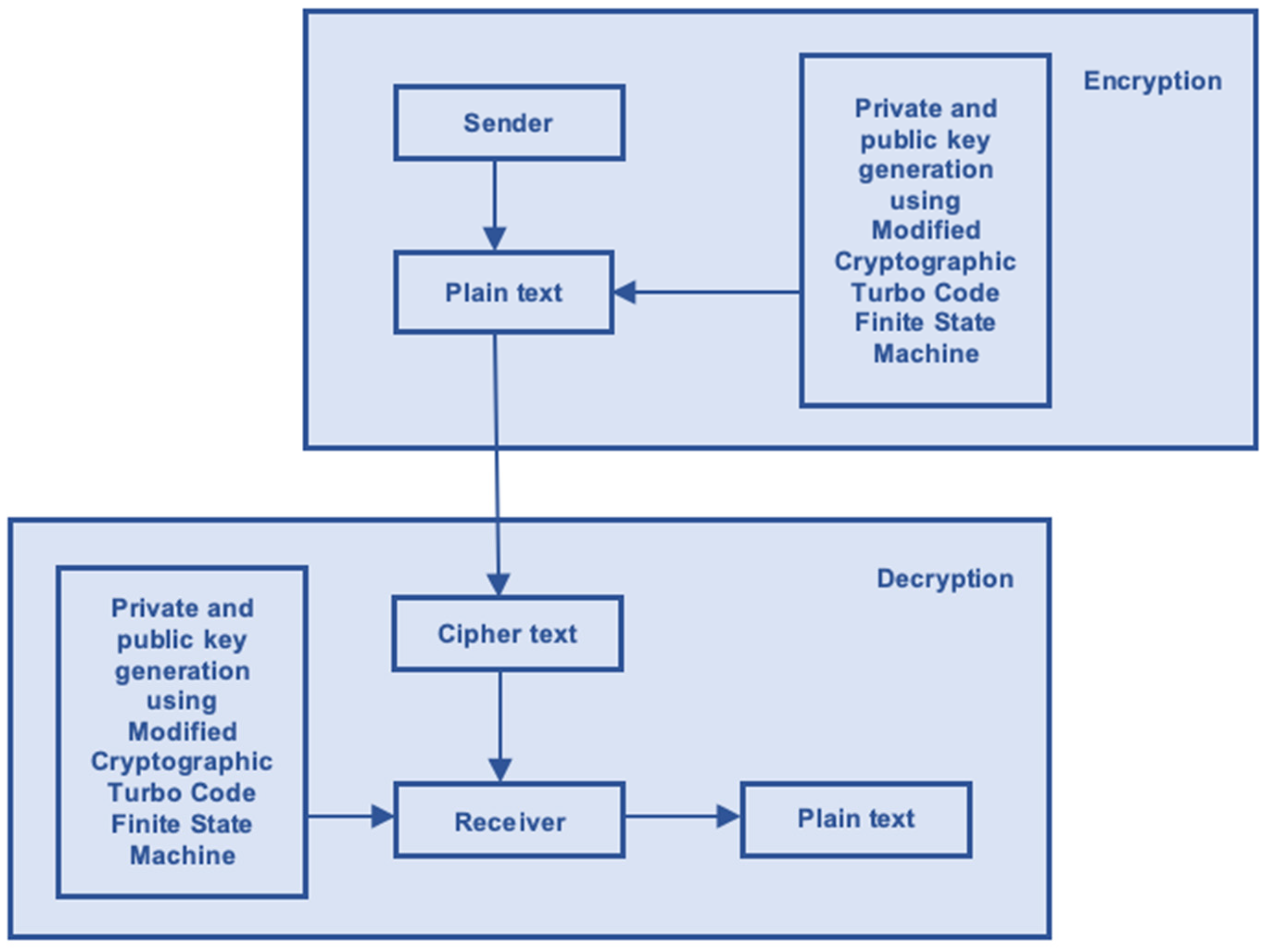
Figure 1 is a schematic depiction of the status of symmetric key cryptography. When given a Plaintext (P) and a key (K), symmetric cryptography generates an encrypted message (C). It is possible to encrypt the Plaintext (P) using a secret key (K) and decrypt it using the same key. Given the amount of rearranging and shuffling that took place, the connection between the ciphertext and the Plaintext is, at best, obscure. Subtly altering (P]) by diffusion [
2] sets the stage for the intricate interplay between neighboring symbols. The product cypher technique allows for bidirectional obfuscation and dissemination.
The channel is used to send incoming messages to the source encoder with the best feasible data rate and accuracy [
3]. The first encoder may read the symbols as code words. There is a unique coded message associated with every symbol. Before a source decoder can convert the output of a binary channel decoder back into a symbol sequence, it must first perform the inverse mapping of the source encoder’s code words. Incorrect binary sequences may have been sent due to interference in the signal’s path to its destination. Channel coding [
4] methods are useful for eliminating this kind of mistake. Channel encoding involves an encoder at the transmitter end adding additional bits to the output of the source encoder using an al-algorithm. Information encoded in channel 1 might be decoded by a channel coding block decoder at the receiving end. Many error-correcting methods are used in channel encoding to ensure that the original bit sequence may be recovered in its entirety.
Copyright protection and preventing malicious manipulation are the most pressing and difficult issues. Research suggests that keeping secrets might help alleviate these sorts of concerns. Covert data storage in media may be useful for a variety of purposes, such as facilitating the identification of images, safeguarding intellectual property, and regulating access. The integrity of the message would be compromised if information were distorted in a way that was not immediately obvious to the human eye. When dealing with overly sensitive information or medical imaging, even a little bit of inaccuracy might have serious consequences. Reverse Data Hiding (RDH) [
5] provides information on how to inject data into digital media without any quality degradation. After data has been extracted from digital media, the whole storage device may be retrieved. The owner of the picture has little reason to trust the cloud service providers, since they will almost certainly encrypt the shot before uploading it. The picture restoration and analysis processes must be carefully separated for usage in medical and defense applications. The original photo should be encrypted using the owner’s public key. The data hider uses a data-hiding key to include the information into the encrypted signal. After receiving the information, it may be decoded from the image. If the sender and receiver both have the data-hiding key, the recipient may decode the sent signal without knowing what is in the encrypted data. Therefore, even if the re-receiver has the cypher [
6], they cannot decode the data in the image without also obtaining the corresponding cypher. His cover photo might be obtained via public decoding of the encrypted signal he was allegedly sent.
The use of the Modified Cryptographic Turbo Code Finite State Machine (MCTC-FSM) is expanding into new domains, such as privacy protection [
7], encrypted image authentication, and authorship verification. One major drawback of current methods is that the encoded information can only be accessed either before or after the image has been decoded. Thus, the MCTC-FSM method has been validated as a practical choice for both secret extraction and image recovery. Most TC methods may be an improvement over what has come before, but none of them can ensure complete success when it comes to extracting data or restoring images. Due to their prohibitive computational cost, slow embedding rate, and inadequate security [
8], these approaches are not well-suited for usage in real-time applications. The proposed work includes a ground-breaking MCTC-FSM technique with robust security, complete cover and secret reversibility, and a large embedding capacity at a reasonable cost. In this research, we provide a unique MCTC-FSM method based on two-level embedding. The cypher text may be incorporated into the cypher image using this method, even if the cover and secret are unknown. Only those in possession of the corresponding decryption keys will be able to read the encrypted information. The suggested methodology improves the quality of both embedding and encryption, with correlations tending towards zero and histogram values becoming uniform. The final image should have an SSIM of 1, a BER of 0, and a PSNR of infinity.
1.1. Motivation
Error-control coding is a method used to improve a channel’s resistance to interference. The proper unity between mathematical modelling and efficient algorithms, and more critically the realization of this principle in actual systems, is essential for data transfer that is both quick and secure. To code channels in a way that comes close to the Shannon limit, Turbo Code (TC) is a major contender. The bit error rate (BER) performance of currently available Turbo Codes is vastly enhanced, either in the waterfall zone or the error-floor region, or both. Yet, the flattening effect is an issue for most forward-correcting codes. Yet, the development of communication technology calls for an overly complex coding scheme with great potential to address this problem. As a result, the development of better TC designs has been a hot topic in the scientific community during the last several decades.
However, from the early nineteenth century, a large amount of study has been conducted in the field of computing intelligence approaches. Scientists have successfully implemented these algorithms to improve the efficiency of modern communication networks. Existing linear programming methodologies, such as Pentagrid’s method, Bellman’s theory, etc., cannot simplify the complexities of real-world engineering challenges and cannot produce stable optimum values for multi-optima-based rough surfaces. Considering this, the development of strong meta-heuristic algorithms inspired by nature and their use in a wide range of engineering issues has arisen as a new and significant topic of study.
The literature has sparked some fresh ideas for creating more effective TC. As adding another dimension to a Turbo Code (TC) significantly boosts the system’s BER performance, this study tries to build both enhanced Three-Dimensional (3D) and unique Four-Dimensional (4D) TCs. A new modulation method called Superposition Modulation (SM) has been included into this setting. In addition, the unique Simple Augmented State Diagram (SASD) method has been used to assess the suggested 4D-performance TCs. Moreover, utilizing the finite length rule and the asymptotic spectral shape function, an in-depth investigation of the asymptotic behavior of the innovative hybrid interleave-based 4D-TC has been performed. By using the time-slicing and interleave-gain technique, we have also analyzed the worst-case upper limit of the suggested structure. Improved versions of previously developed algorithms inspired by nature have also been successfully utilized in the effective design of the TC. Lastly, the suggested TCs’ BER performances based on existing communication standards such as WiMAX and WIFI are discussed.
1.2. Significance
During the last several decades, the efficient design of Turbo Codes (TCs) for cutting-edge communication systems has been a hotbed of innovative study. Scientists have proposed numerous helpful methods, which can be roughly divided into five categories: TC structural analysis, TC ensemble analysis, TC energy allocation strategies, TC design with optimization approaches, and TC application with multiple structures in contemporary communication systems. It has been shown that either increasing the number of effective encoding and decoding modules or developing a competent interleaving unit may boost TC performance in this regard. In this context, the optimal puncturing pattern has also been thought about. Optimal power sharing between systematic and parity bits has also been studied. The top limit of BER for both 2D and 3D Turbo Codes has also been evaluated using a variety of ensemble methodologies including the state diagram methodology. As a bonus, by using several computationally clever methods, optimal TCs have been designed with remarkable efficiency. Several goal functions have been developed for this purpose, considering critical coding scheme characteristics. Considering these considerations, the primary goals of this thesis are as follows:
First, creating energy-saving designs, a revolutionary Modified Symbiotic Organism Search (MSOS) algorithm is combined with several Superposition Modulation (SM) power allocation strategies to create a 3D Turbo Code (3D-TC).
Symmetric key cryptosystems are used for both data encryption and decryption in the proposed system. The input was a 3 × 3 matrix, which is a shorter matrix and, hence, simpler to solve. To add insult to injury, the key was produced using a range of bits from 16 to 255, which is too small to use a Finite State Machine and so makes the system vulnerable to cracking. We may extrapolate the following from this observation:
(a) The security of a cryptographic system cannot be ensured by using a single key of insufficient length. To prevent hackers from having any hope of cracking the encryption, it is advised that long-length keys are utilized.
(b) An intermediate cypher must be established to keep data secure from hackers, and it is preferred if dynamic keys are employed.
(c) Key transfer through a secure channel should be unnecessary if keys can be generated from publicly available information.
The article is divided into introduction, methods, experiments, results analysis, summary, and recommendations for further study.
2. Literature Survey
Steganography [
9] entails encrypting secret information inside a seemingly benign picture. Heavy embedding, on the other hand, drastically alters the cover picture, which flags the presence of embedded data. Thus, steganography is typically insufficient for securing massive volumes of disguised data. Data security may be improved by combining encryption with other methods, such as steganography. Encryption relies on a mathematical function to encrypt data, making it unreadable by anyone except the intended recipient. The data is encrypted, but it may be snooped on if it is transferred through a wireless channel. When combined with encryption, steganography is one of the most effective techniques to conceal sensitive data [
10]. To be effective, software must be able to restore both the secret information and the cover media without tampering with them.
Reversible Data Hiding (RDH) may be used to decode and decrypt both the cover picture and the secret data since it is a lossless embedding mechanism. Researchers are now focusing on RDH in encrypted domains, also known as RDH in Encrypted Domain (RDH-ED). In the RDH-ED framework, there are two categories, separable and non-separable, which reflect whether the hidden information can be recovered. Independent RDH-ED allows for data decryption without disclosing any sensitive keys. Nevertheless, in the case of non-separable RDH-ED, the cover picture must be decrypted before the hidden data can be accessed. Puech initially presented the non-separable RDH-ED cypher based on the original cover art’s Advanced Encryption Standard (RDH) [
11] encryption.
Before decrypting the encrypted image and analyzing its local standard deviation for the hidden image, we first mark it. Obtaining the secret information is impossible without first decoding the cover art, making this technique inseparable from the cover art itself. This technique is simple to develop; however, it has a low embedding capacity of only 0.0625 bpp (bits per pixel).
Zhang proposes a another RDH-ED approach in [
12] that includes encrypting the original cover picture using an exclusive-or (XOR) operation. By carefully examining each individual component, we were able to put together the whole image. A line was drawn through the middle of each cube to separate the spaces. To conceal the information, we need to switch the three Least Significant Bits (LSB) of each pixel in a particular section of the block. This technique may simultaneously reveal the cover art and the secret data to the recipient. If the block size is off, extracting data or restoring images will fail. Using a new estimate equation and side-matching algorithm, we enhance embedding capacity and drastically reduce the error rate between neighboring blocks in approach [
13]. Because data recovery requires decryption of the picture, this technique is a non-separable RDH-ED, developing differentiated histograms of data and adjusting preexisting ones [
14].
The security and dependability of a system are compromised when error-correcting codes are used with other security mechanisms. The necessity to enhance the current ME technique [
15] with multi-bit error correction and a larger embedding capacity and reversibility inspired the proposed study.
Further secret information may be added to a steganographic [
16] picture by giving it the illusion of encryption. The cover image may be reversed if you reveal the hidden words on the FSM’s map of its whereabouts. The cover image’s components have new homes after being embedded, and the map showing where they will be kept is called the location map. At the receiver, a position map may be extracted from the codewords to reconstruct the parts of the cover picture that were untouched by the changes made during embedding. Integrating ME with FSM, which employs a cryptographic FSM, would allow for the embedding of secret data and a cover picture with improved quality, security, and reliability.
Issues and Challenge
This suggested effort aims to improve the reliability and security of data transmissions. Steganography is the practice of hiding sensitive data within an apparently innocuous picture. This method protects sensitive information but offers few opportunities for embedding. The quality of the restored cover image likewise suffers when more embedding is applied. Encrypting the steganographic image is one way to boost embedding capacity without sacrificing security. Information that has been encrypted or hidden via steganography may still be vulnerable to channel noise. [
17] One possibility is to implement an error-correcting coding scheme. The total cost of computing rises due to the three-step process of steganography, encryption, and error-correcting code required to guarantee the security and dependability of the transmitted data. The updated ME incorporates the concealed data first into a cover photograph. The improved ME was created for maximum embedding effectiveness.
Table 1 shows the Comparison of Existing Methodology and their demerits.
The suggested Cryptographic Turbo Code is used to encrypt and encode the steganographic image (an embedded cover picture). It is recommended in the Modified Cryptographic Turbo Code (MCTC) that a secret-key FSM should replace the regular FSM, thereby making it a variant of the FSM. With the secret key, a secret-key FSM encrypts the data and corrects transmission problems by shuffling the bits of the input into a new sequence [
29]. As an alternative, we suggest using a cryptographic FSM based on elliptic curves to produce random bitstream noise (MCTC-FSM) [
24]. The sensitive data is protected on two fronts by the joint efforts of the Modified Minimum Encryption and Minimal Common Transceiver Complexity. This may be achieved by using a steganographic image to covertly conceal the information and then encrypting the whole thing [
25]. The cover photo’s security and embeddability are both improved by using a steganographic picture for encryption. Recovery quality suffers as embedding capacity rises because more advanced embedding methods change more of the cover image’s bits. To get around this issue, the MCTC authors suggest relaying the in-codeword locations of the changed bits through syndrome embedding. Hence, the receiver can decode both the altered bits of the cover image and the hidden data included inside the steganographic picture. Data embedding might be conducted backwards [
30].
Due to their reliance on a physical map, current RDH-ED systems can locate the appropriate cover image, but they are unable to insert it. To fill up the discovered knowledge gap, it will be necessary to enhance embedding capabilities via reliable recovery of the cover art. When it comes to correcting bugs, Turbo code is unparalleled. On the downside, it does not safeguard information during transmission. The bit error rate could be decreased by using TC in conjunction with encryption. The present MCTC-FSM is quite effective at detecting and repairing errors. Yet, they might be built with cryptographically safe encryption and portable data storage in mind. There is a known void in the literature about the development of a cryptographically sound FSM that can create a random interleaving pattern at an affordable computing cost.
3. Proposed Methodology
The classic method accomplishes security and reliability via a cascade implementation of the traditional cryptography system and the error-correcting coding scheme. To ensure the safety of the sent data, it is first encrypted and then the transmission channels are encoded. Information received must be decoded and encrypted at the receiving end before it can be used to reconstruct the original message. The Advanced Encryption Standard (AES) is an algorithm for secure data transmission that has been recommended for use. For the goal of data security, it is often used in systems with constrained means, such as satellites.
The performance of a convolution coding unit connected in parallel mode can be assessed from the Input Redundancy Weight Enumerating Function (IRWEF) of the converged constituent recursive convolution code
as given by
where the coefficient
implies the coded strings number-devising parity check weight spawned by an input bit stream of weight
. Here,
and
suggest two dummy variables.
The Conditional Weight Enumerating Functions (CWEFs)
and
of the encoding modules
and
can be specified in Equation (2) and Equation (3), respectively.
Here,
and
signify the coefficients of the weight enumerating function of the encoding modules
and
, respectively. These coefficients denote coded strings with parity check weight
produced by input bit string of weight
. Now, by picking up the appropriate value of
which is the input factor and N is the pixel range, the fractional part of the parity sequences of length
and
from
and
are amassed by a
multiplexing unit to create the coded bit sequence of length
. Therefore, the CWEF [
17] of the multiplexing unit which accrues the fractional sequence approaching from convolution encoders connected in a parallel fashion and detached by an interleaver of size
is specified by:
The authenticity of Equation (4) has been assessed by considering the following norm: It states that the interleaver of length should map a set of incoming bits of weight into all of its dissimilar permutation with identical probability . Now, the output of the multiplexing unit is permuted by the interleaving unit with a length of . Therefore, the CWEF of the interleaving unit is given by Equation (5).
Where and characterize the input weights of the tracks and , respectively, which are connected to the puncturing module. In this context, and represent output weights of the bit strings coming from the puncturing unit. The weight of the output code sequence impending from the post-encoding unit is signified by . Additionally, and characterize the input weights of the tracks and , respectively, which are connected to the puncturing module.
The straitened higher bound on the BEP for the ML soft decoding technique under the Additive White Gaussian Noise (AWGN) channel condition can be evaluated by the Input Output Weight Enumerator Function (IOWEF) coefficients
. The straitened higher bound of 3D-TC assuming BPSK modulation is specified by
where
signifies the code rate. A flowchart of the proposed work is shown in
Figure 2.
To provide security and dependability, RDH and the FSM combine to provide excellent security but with a drop in dependability compared to the original implementation of FSM. As the RDH-128, RDH-192, and RDH-256 all use keys of length 128, 192, or 256 bits to encrypt and decode 128-bit data blocks, this makes sense. This limits the 4-FSM’s error-correcting capability by limiting the maximum frame length of the FSM to 128 bits. A longer input bit sequence may improve the MCTC-error-correcting FSM’s performance. Nevertheless, encoding a bit sequence longer than 128 bits necessitates many iterations of MCTC, which increases the time and energy needed to process the data.
In this scheme, the
length-based input sequence is passed through the Serial-to-Parallel (S/P) unit. Thereafter, symbols impending from the
unit are moved through the Binary Phase-Shift Keying (BPSK) segment. Next, the amplitudes are assigned to each of these symbols. Finally, these symbols are linearly superimposed to generate a finite-alphabet output symbol
. This whole modulation arrangement can be mathematically articulated by the expression
where
indicates the magnitude of the
binary chip and
. Three power distribution techniques, namely Equal Power Allocation (EPA), Unequal Power Allocation (UPA), and Grouped Power Allocation (GPA), have been successfully used for the design of the efficient 3D-TC.
Instead, one might modify the existing FSM implementation in such a manner that it provides security and error correction at a reduced computational cost. The only function that the conventional FSM can achieve is to correct errors in the data during transmission; this is a limitation. However, the random shuffling that the random FSM conducts may be used for encryption as well, so it is not only for fixing mistakes.
3.1. Cryptographic Turbo Code
The MCTC is a proposed modification of the FSM that provides additional reliability and security for data while it is in transit. The MCTC system is composed of the transmitter, which has an MCTC encoder and decoder as well as an FSM, and the receiver, which contains an FSM. Before transferring the data through a transmission channel, the MCTC encoder first encodes and encrypts it using the private key that it has been given.
3.2. Cryptographic Turbo Code Encoder
Figure 3 depicts the architecture of the MCTC encoder that is being considered for use.
Figure 1 illustrates the shift register implementation of the transfer function of each RSC encoder. The delay in the shift register is denoted by the E in this equation.
An MCTC sits in between the two RSC encoders to provide separation. The input bit sequence A, which is delivered to the MCTC, is given to the first RSC encoder, which then encodes the sequence.
It is sufficient to send either the A or the B systematic bits since they are both equivalently represented by scrambled copies of the other. However, to prevent the data from being stolen, the MCTC will send out systematic bits, B. In addition, to prevent the confidential data from being guessed by a user who is not permitted to access them, the code word of the first encoder is interleaved with MCTC-2 to produce the letter E. The MCTC’s code word is referred to as MCTC, and it is provided as:
The term “code rate” refers to the proportion of the number of information bits to the number of encoded bits. The amount of information bits included in the MCTC is L, while the number of parity bits is 2L. This combination yields a coding rate of:
On the other hand, this results in an increase in the system’s bandwidth. An increase in the code rate and a decrease in the code’s bandwidth cost may be achieved by puncturing the parity bits or removing some of them. A decrease in the performance of the code’s error-correcting mechanism is brought on by puncturing; however, a competent puncturing technique may keep this decrease in performance to a minimum. In the field of cellular transmission, the rate of 1/2-pierced FSM is used. The secret word for the rate of 1/2 MCTC is as shown in
Figure 3.
Figure 3.
Cryptographic Turbo Code (CTC) encoder using MCTC FSM.
Figure 3.
Cryptographic Turbo Code (CTC) encoder using MCTC FSM.
When it is time to decode the information, the decoder will substitute false bits with a value of zero for the bits that have been punctured. This will allow the information to be decoded. When the RSC encoders have completed encoding all the bits in the input bit sequence, they must reset to an all-zero state before going on to the next input sequence. This ensures that the encoders are ready for the next input sequence. To reset all the shift registers to their original state, which is all zeroes, the input bit sequence is extended with what are known as termination bits, which are also called tail bits. Termination bits are introduced into a code at the end of each code word. This is performed to ensure that the error-correcting performance of the code does not deteriorate because of the introduction of the termination bits.
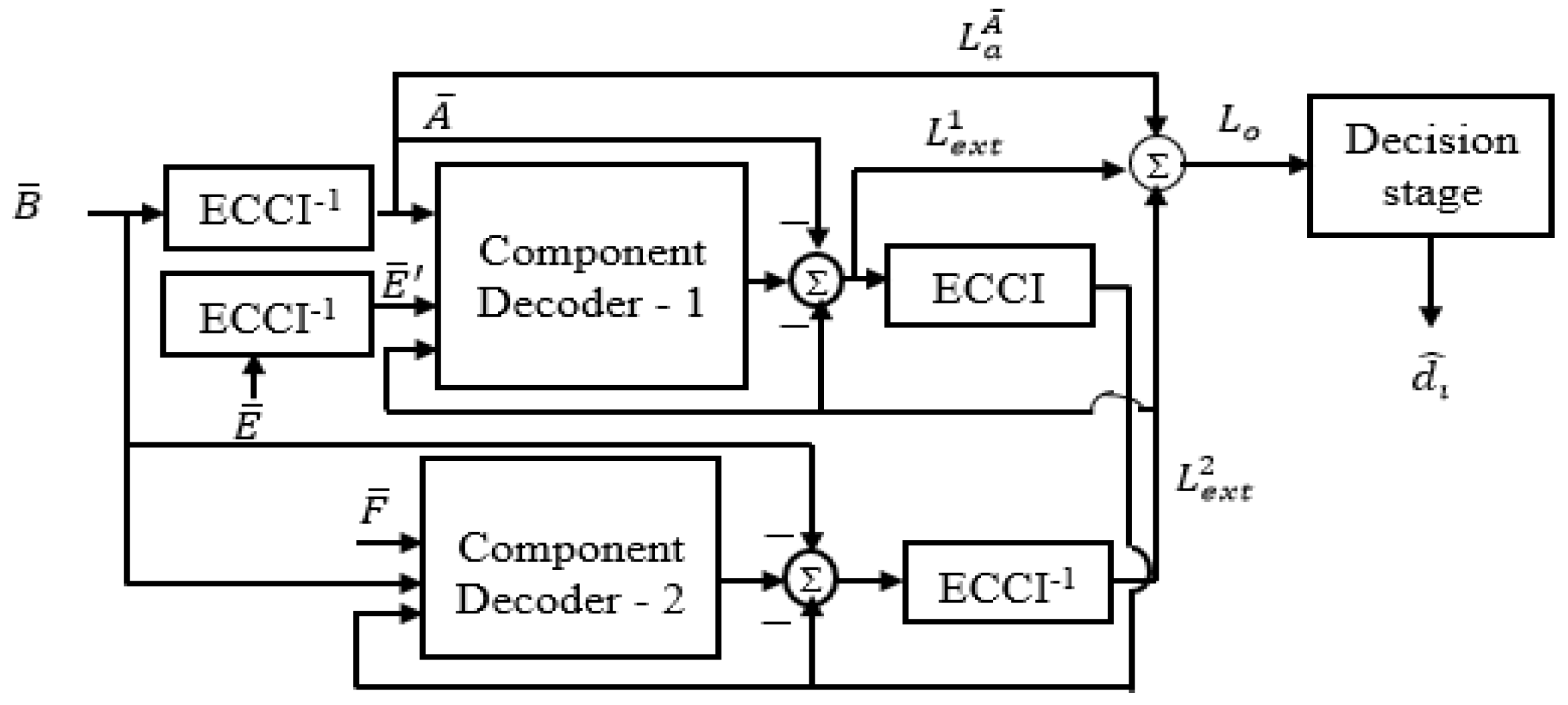
3.3. Decryption of The Cryptographic Turbo Code
Figure 4 provides a visual representation of the structure of a CTC decoder. The noisy bits that are received are “C-C-T-C,” which equals “B-E-F.” The MCTC de-FSM first performs a de-interleaving operation on the received bits B to produce an A using the keys km, ks, P, and G that are shared by the sender and the receiver. This process is repeated until the desired output is achieved.
The iterative procedure will continue until the estimates produced by the two decoders tend to converge on one another. The iterative decoding technique that is employed in the TC enhances the performance of the error correction with each subsequent iteration.
3.4. Finite State Machine with Reverse Data Hiding
For the
received bit, the decoder computes the algorithm of the Likelihood Ratio (LLR),
as
Equation (11) shows the data-hiding text-using Finite State Machine with the Likelihood Ratio and message.
If the receiver uses the incorrect key to the FSM, the decoders receive incorrect bit sequences
and
, thereby recovering the incorrect information shown in Equation (12).
where (
u) is the mapping function.
A secret number is used in conjunction with a complicated procedure on a computer to encrypt and decode data. To prevent unauthorized parties from understanding sensitive information sent over public networks, it is necessary to encrypt the message before sending it. Only the receiver to whom they are addressed should be able to decode them. A communication encrypted with a key should be decipherable only by the owner of the same key.
In traditional TCs, the input data are interleaved with a well-known permutation pattern that is intended to increase the efficiency of the coding process. This makes it possible for a random FSM to be employed. However, to store the interleaving pattern, the random FSM needs an additional memory and, to send data to the receiver, it needs a wider bandwidth (
Table 2).
The development of a key-based cryptographic FSM that can create an extremely random output on the fly is a difficult task, which is one of the primary motivations for the work that is being suggested here. In this line of study, a proposal has been made for a cryptographic FSM that uses a secret key and is known as the Elliptic Curve Cryptographic FSM (MCTC). This is performed to protect the pattern from being accessed by those who are not permitted to do so. The interleaving sequence that is produced by the MCTC is overly sensitive to the fact that the MCTC has a secret key. When the secret key is altered, the interleaving pattern also undergoes considerable revision, which makes it impossible for an unauthorized user to deduce the order in which the inputs will be sent.
Elliptic curve cryptography is a typical encryption procedure that offers a high degree of protection to the data that is sent from a sender to a receiver over a public network. This level of protection is provided by the elliptic curve. The elliptic curve equation must be satisfied by a cloud of points for the elliptic curve arithmetic to be performed, since this is the basis for elliptic curve encryption. The positive integers a and b satisfying the curve equation that defines the points on the elliptic curve Ep(a, b) over a finite field Fp is as follows:
The domain parameters, also known as the parameters of the elliptic curve, a, b, and p, describe the point (x, y) on the elliptic curve in such a manner that both x and y are contained inside a finite field, Fp. These domain parameters are also known as the elliptic curve parameters.
This is the lowest positive integer that might possibly fulfil the requirements of the condition. The security of the cryptosystem may be ensured by choosing the value of p that will be a large prime integer. This will produce an elliptic curve of high order that contains many points, which will satisfy the requirements for safety.
The creation of a top-secret lookup table is the first step in the implementation of the MCTC that has been suggested. This step is subsequently followed by the development of interleaving locations. Let us assume that the point G on the elliptic curve of prime order Ep is a concealed generator (
a,
b). The most top-secret lookup table is created using computational techniques
where
is a point on the elliptic curve.
where 𝑄
𝑑 is the collection of elliptic points that are concealed inside the index t of the lookup table.
The key 𝑘
𝑚 may have a single bit altered, which will cause a whole new lookup table to be generated, as shown in
Table 3. This protects the private lookup table from being read by a third party who is not authorized to examine it in any capacity. Both the transmitter and the receiver make use of two hidden parameters that they refer to as
G and 𝑘
𝑚. These parameters are only known to the transmitter and the receiver. These parameters are accountable for ensuring that the confidential lookup table’s privacy is always preserved. In addition, even if the adversary is successful in learning one of the secret parameters,
G or 𝑘
𝑚, the ECDLP that is used in elliptic curve arithmetic makes it exceedingly difficult for them to uncover the other secret parameter.
The MCTC oversees creating the interleaved bit locations v for each input bit location u that it receives, and it is accountable for doing so. The MCTC is the one responsible for producing the interleaved bit location v, which serves as the index of the secret lookup table. This index is associated with the elliptic point 𝑃
𝑢, which can be determined using the formula
where 𝑘
𝑠 is the secret key and 𝑃 is a secret elliptic curve point given to MCTC.
Table 3 provides an illustration of the case that may be used to explain the production of an interleaved bit location for the mask key 𝑘
𝑚 = 2,853,234. Case 1 and case 2 demonstrate the positions of the interleaved bits for the same secret key 𝑘
𝑠 but for different secret points, P. Even if the keys 𝑘
𝑚 and 𝑘
𝑠 are the same, the interleaving sequence is completely different because of a change in P, as can be seen in the results for cases 1 and 2. Cases 2 and 3 demonstrate that even though P remains unchanged, the generation of a totally new interleaving sequence is brought about by a single bit shift in the secret key, 𝑘
𝑠. According to the findings, the user must be in possession of practically all the secret key parameters to successfully recover the right interleaving pattern. An entirely new sequence is generated if there is a modification to even one of the parameters.
Every FSM has a matching de-FSM that works on the interleaved sequence to construct the sequence in its natural order. This order is maintained throughout the process. To de-interleave the sequence that has been interleaved, the receiver will need to construct an interleaving sequence that is awfully close to the one that was sent. It is possible for the receiver to produce a comparable interleaving sequence by secretly broadcasting the keys “𝑘𝑚, 𝑘𝑠, G, P.” Because of this, there is no longer a need for additional bandwidth, which was necessary to share the whole table between the sender and the receiver.
While using a secure system, an adversary is rendered incapable, or at best exceedingly improbable, of regaining access to the original data. Because of this, one of the most important criteria for a secure system is the ability to generate and transmit random data. Since the random output is hard to anticipate, it makes it difficult for an adversary to launch an attack on the system. Because the output that is created is more random, the data that is collected is also more unexpected, which gives the system an increased level of safety.
4. Results and Analysis of Proposed Work
The primary purpose of the recommended MCTC is to provide a shuffling pattern that is both surprising and completely at random. It is possible to evaluate how much unpredictability the MCTC really injects into its output by using several different randomization tests. In the SIPI Database, the miscellaneous volume consists of 44 images, 16 color and 28 monochrome. The sizes are 14 lots of 256 × 256, 26 lots of 512 × 512, and 4 lots of 1024 × 1024.
The randomness test is an empirical procedure that involves a set of tests designed to evaluate how random a certain sequence really is. The statistical characteristics of the random numbers that are generated may be checked, and several different statistical tests can be used to determine the extent to which those statistical qualities are met. The results of these tests indicate the presence of a pattern in the sequence. When a sequence displays a pattern, it is an unmistakable sign that the sequence is not random. This renders the sequence both predictable and susceptible to being targeted by an adversary.
The amplitude, direction, and form of the link between the input and output may be seen with the use of an MCTC scatterplot. When looking at the correlation coefficient, a result that is high is indicative of an extraordinarily strong link. A pattern in which there is no obvious center and a practically null CC would be a great depiction of a random Finite State Machine (FSM). Dispersion, on the other hand, is a statistical metric that is used to evaluate how much of a stretch there is in a certain distribution. If the dispersion value is made higher, the locations of the bits that are interleaved will become more spread apart. NIST FIPS-140-2, the industry-standard statistical test suite, is used to provide further verification on the proposed MCTC’s statistical characteristics. In the following, you will find a detailed explanation of the different examinations.
A scatter plot may be used to illustrate the unpredictability of the output sequence. It is desirable for the scatter plot to contain points that are distributed in a way that is both random and consistent. If the scatter plot displays a pattern that can be predicted, the parameters that were used to construct the sequence may be uncovered, which would leave the cryptosystem vulnerable to attack.
The bit locations in the input and the bit positions in the output have absolutely no link with one another, as is seen from the picture. Altering the values of 𝑘𝑠 also results in a striking transformation of the pattern. Because of this, the scatterplot ensures that the random numbers that are generated are one-of-a-kind for each user and are founded on the MCTC keys that they have. The link between the MCTC’s input and output is one that is overly sensitive to the way its key is configured. An opponent who does not possess the relevant keys will be unable to discern the connection between the bits that are input and bits that are output because of this. This time, the test was conducted between two interleaved bit location sequences known as vi and vi+1. Both sequences were produced by the MCTC using the ith and (i + 1)th secret key and an interleaving length of 20,000 bits. The interleaving sequence was generated with the use of an elliptic curve with the parameters E19991(3,1), 𝑘𝑚 = 49853, G = (52,17), and P = (62,2).
As a result of the points being evenly distributed around the graph, it is hard to draw any conclusions about the nature of the cypher or their connection to one another that are relevant.
This indicates that the association is not extraordinarily strong. Because of this, it is exceedingly difficult for an unauthorized user to anticipate the interleaving pattern due to the low value of the correlation (
Table 4).
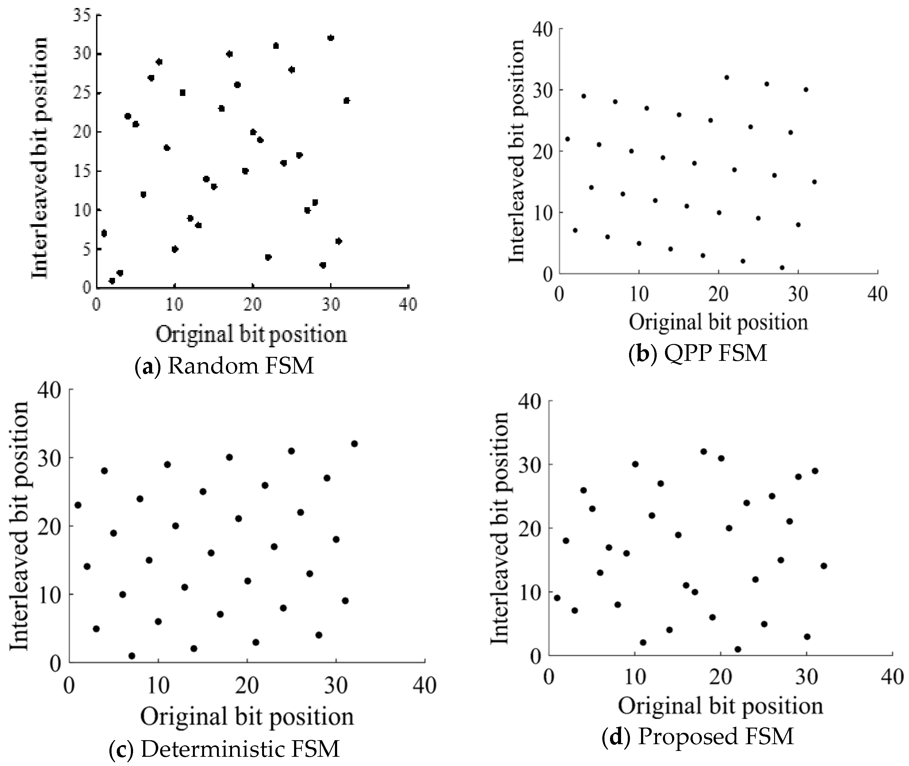
The Quadrature Permutation Polynomial, also known as QPP; the random FSM, sometimes known as RI; and the deterministic FSM, often known as DI, are all frequently used by the TC. It was determined whether the MCTC, QPP, RI, and DI had all been generated in a random fashion. In
Figure 4, a comparison is made between the scatter plots of the RI, QPP, DI, and MCTC. The output sequence can be seen in the figure because QPP and DI are interleaved in such a way that makes it visible; as a result, the output sequence is predictable and open to attack. However, the interleaved bit sequence may be easily determined by an authorized user based on the original bit sequence, even though both the RI and the suggested MCTC demonstrate a large degree of unpredictability in the pattern (
Figure 5).
To calculate the normalized dispersion and spreading factor of the proposed MCTC, simulations were run using an input bit sequence of lengths 133, 499, and 2019, correspondingly. This allowed for the determination of the normalized dispersion and spreading factor.
According to the information shown in
Table 5, the value of the RI standard deviation is somewhere around 0.8. Because the suggested MCTC has a dispersion value that is close to that of the RI, it is possible to use it as a method that interleaves bits in a way that is both effective and efficient. In addition to this, it comes as quite a shock. Despite this, the DI and the QPP both exhibit a little degree of dispersion to varying degrees. This is a direct consequence of the fact that the DI and QPP generate a predictable interleaving pattern for the data they process (
Table 6).
4.1. Security Checks for Cryptographic Module According to FIPS 140-2
FIPS-140-2 is also known as the Federal Information Processing Standard. Four statistical examinations are carried out by the FIPS-140-2 during a binary sequence that is 20,000 bits in length. The mono-bit test, the poker test, the run test, and the long-run test are the names of these respective tests. A minimum of one hundred binary random sequences are required to be used to carry out the test in an appropriate manner. In each experiment, the value of the statistical parameter that has been supplied is calculated for the binary sequence that has been defined. When the value of the test parameter has been calculated, it is then compared to the range of acceptable values that has been established for that specific test. If it falls within the acceptable range the test is considered successful. If the parameter being evaluated is found to fall within a range that is considered acceptable, the binary sequence will provide a positive result. For the random binary sequence to be eligible for use in cryptography it is required to fulfil all the prior requirements. Failing to do so will result in the sequence not being regarded as suitable for use. The following is a list of the tests that are included in the FIPS-140-2 certification.
It is reasonable to anticipate that, in a sequence of ones and zeros that was created at random, approximately half of the bits in the sequence should be ones, and the other half should be zeros. This is because one is the binary representations of the values one and zero is the binary representation of the value zero. The frequency test verifies that the total number of ones and zeros that constitute the sequence do not significantly differ from one another. This guarantees that there is a natural flow to the sequence.
- 2.
Poker test:
The bitstream that is going to be analyzed has been sectioned up into subcomponents that each comprise four bits, considering that F(i) stands for the count of each of the four-bit values.
- 3.
Run test:
A run is the term used to describe an unbroken string of bits that are all the same. With the run test, a tally is taken of the number of runs of ones and zeros of varied lengths that are present in the input sequence. These runs may be of varying lengths. The value of the test parameter known as Tr is determined by the number of ones and zeros that are present in a certain bitstream.
- 4.
Long run test:
The value of the test parameter Tl must be more than or equal to 26, and it is determined by counting the number of consecutive ones or zeros that are not broken up in any way. If the bitstream does not include any runs of this sort, then the test may be regarded to have been successful.
Estimates were made for the test parameters for each of the four tests based on around one-hundred different binary sequences that were generated by the MCTC that was recommended. During the generation process, a one-of-a-kind private key was used to construct each binary sequence of length 20,000 utilizing that sequence. The binary sequence was created by converting each of the random numbers that were produced by the MCTC into a bit, bi, by utilizing the binary representation of the numbers that were obtained by calculating
The results of three of the examples are shown in
Table 7, which demonstrate that the test value is located within the appropriate interval for each of the four statistical tests required by the FIPS 140-2.
4.2. Periodicity Analysis of Elliptic Curve Cryptographic FSM
The MCTC makes use of a cryptographic FSM that, all the way along its length, randomly permutes and distributes the data that it gets as an input to provide the highest possible level of security. This was performed so that the MCTC could give the largest possible degree of protection. After an interleaving period of that length, the MCTC will then proceed to repeat the permutation sequence N times in each of its subsequent cycles. This will continue until the sequence is exhausted. The passage of time results in an increase not just in the number of feasible combinations but also in the degree of unpredictability in the bits that are created, which ultimately leads to an increase in the total number of combinations that are conceivable. The number of bits encoded by CTC is equal to the frame length, which is denoted by the letter L in the frame length notation. This is the case because the number of bits encoded by CTC is equal to the frame length. If you want each frame to be long enough to interleave the input bits, the bits themselves need to be at least as long as the period of the FSM. The bits that are interleaved are sufficiently random when N is big enough to accommodate them. Because of this, there is less correlation between the code words and, as a result, error-correction performance in CTC is enhanced. Nevertheless, when N is quite low, the interleaved bits are not nearly as random as they should be. This occurs because the interleaved bits are determined by N. Interleaved bits make use of the higher statistical properties offered by huge periods of time, which makes it much more difficult for an adversary to determine the specific interleaving pattern.
A certain amount of time must pass before an interleaving sequence may begin repeating itself; this minimum amount of time is referred to as the sequence’s period. The period of an interleaving sequence is the same as the sequence’s period. If each of the criteria that are given below is met, then we may say that the series of numbers has a period of N, where N is an integer that is greater than zero. If all these conditions are met, then the sequence of numbers has a period of N
where the letter “i” denotes a particular location inside the integer v. The periodicity of the proposed MCTC is largely governed by several different parameters, the most significant of which is the number of points on an elliptic curve that are created by the generator point G. The suggested MCTC is mostly determined by these factors. It is possible to define a cyclic group using an elliptic curve of prime order. The building of a cyclic group results in the production of all the points on an elliptic curve. This is accomplished by selecting a single point from the cyclic group to serve as the beginning point in the process. One point from the collection may be chosen at random to serve as an example of this. An example of a cyclic group is shown in each of the
Figure 6a–c. These groups were generated by an elliptic curve with the order 19 and the generator points (10,11), (7,6), and (16,4), respectively. Each of these figures is shown in its own separate figure. An elliptic curve served as the basis for the construction of each of these groups. In the field of mathematics, an example of an elliptic curve can be found denoted by the notation E17(2,2), which corresponds to this cyclic group. The equation can generate all the points on the elliptic curve, even when the value of G is altered in some way. This is something that can be verified by personal observation. The value of G, which is a variable that can be changed, is what determines the specific sequence that is used to create the point each time. In addition, the point is created by following this sequence.
4.3. Bit Error Rate of Cryptographic Turbo Code
Bits that are sent across a digital communication system incur the danger of getting corrupted if the channel through which they travel is impaired in some way, such as by noise, distortion, interference, fading, or other similar phenomena. It is necessary for a communication system to be able to recognize and rectify problems such as these for it to be reliable. The bit error rate, sometimes referred to as the BER, is a statistic that is used to quantify how well an electronic communication system corrects errors. To calculate it, take the total number of bits that were entered and deduct from that number (
Table 8).
4.4. Proposed MCTC
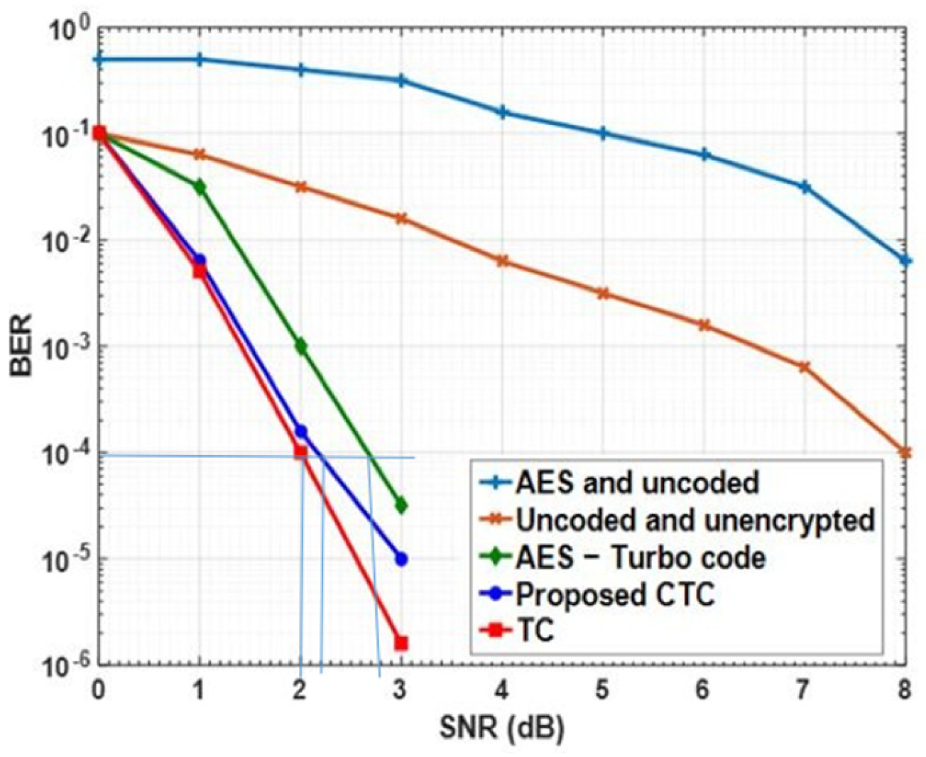
MCTC is responsible for both the encoding and encryption of the bitstream. By combining a bit error rate of around 10-5 with a Signal-to-Noise Ratio (SNR) of 0.7 dB, conventional TC serves as an efficient error-correcting code. Although, there is no encryption during transmission. Given this, the authors of this work offer MCTC as an alternative to error correction for securing data transmission. The proposed MCTC employs an Elliptic Curve Cryptographic Finite State Machine to construct an unpredictable, user-specific, and secure interleaving pattern (MCTC). This method creates the design when fed an elliptic curve and a secret key. The goal is to achieve error-correction performance such as that of the TC with the help of the proposed MCTC, which is designed to successfully decorrelate the code words formed by the CTC. Data sent out by the MCTC using a secret key is protected by the random shuffling pattern and the key itself is kept secret.
Figure 7 compares the bit error rate (BER) vs. the Signal-to-Noise Ratio (SNR) for a non-encrypted system, an MCTC system, a TC system, an MCTC-TC system, and an MCTC system. In contrast to the transmission of data without encoding or encryption, the findings show that the MCTC is less effective at error correction. It is evident since the MCTC is not as good at fixing mistakes. This is because MCTC often leads to errors spreading to neighboring bits. More than half of the bits must be right for the decryption to succeed; hence, even one wrong bit in the input will result in failure. Thus, the Advanced Encryption Standard (MCTC) calls for a second error-correcting code to ensure that the data being transported is legitimate.
In comparison to the original MCTC, the TCs in the MCTC-BER version are much lower. The error-correction performance of MCTC-TC far exceeds that of MCTC because the TC fixes the transmission error. Attempts to employ MCTC-TC to produce a BER on par with a TC have been met with little success so far. For this reason, MCTC is vulnerable to the avalanche effect, which is caused by the bits whose faults have not been corrected by TC. The bits produced by MCTC will be faulty by at least half if TC is unable to fix even a single bit. In addition, the TC’s BER performance is degraded because of the fact that MCTC has a block length of 128 bits, which limits the amount of TC’s frames. The TC and the suggested MCTC have BER performances that are quite similar. The MCTC’s secret key produces private, de-correlated codewords, which is why it is so widely used.
The BER plot of MCTC is shown in
Figure 7; compared to TC, MCTC loses just 0.2 dB of coding at a BER of 10-4, while gaining 0.8 dB when compared to MCTC-TC. The diagram displays this data. The fact that MCTC’s random shuffling is controlled by a secret key also helps to ensure the privacy of any sensitive data it transmits.
The code’s total performance is heavily dependent on how well the MCTC algorithm is implemented. Many factors affect its performance in term of error correction: (i) The MCTC’s architecture; (ii) The number of decoding rounds conducted by the CTC decoder; (iii) the CTC’s frame length.
We analyze how adjusting these parameters impacts the CTC’s performance. The bit error rate (BER) is calculated by encoding and decoding a random bit sequence of 65,536 bits at a rate of 1/2 CTC, sending it via an AWGN channel, and then measuring the number of errors in the decoded version eight times.
- (i)
Effect of the design of MCTC
CTC analysis suggested MCTC for error correction.
Figure 8 shows BER versus SNR scatter plots for each interval. CTC with MCTC has 104 BER at 0.4 dB SNR, 0.2 dB better than CTC with RI. Like the RI, the MCTC randomly interleaves with a dispersion of 0.8. Yet, deterministic FSMs such as the QPPI and SKI FSM use FSM spread to guarantee that permuted bits are no more than a specified distance apart. SKI created both FSMs. A quadratic permutation polynomial generates interleaved bit positions with a broad spread to provide the QPPI error-correcting performance equivalent to the RI. Error correction is achieved by transferring error patterns across decoders. Nevertheless, the SKI length and key affect the spread between interleaved bit positions; thus, a big spread is not always guaranteed. QPPI and SKI feature interleaved bit locations that can take several values, but their patterns are uniformly spaced, making them simple to predict and prone to security breaches. Correlations from the interleaved pattern’s regularity lower the BER curve’s error floor.
- (ii)
Effect of the number of decoding iterations of CTC decoder
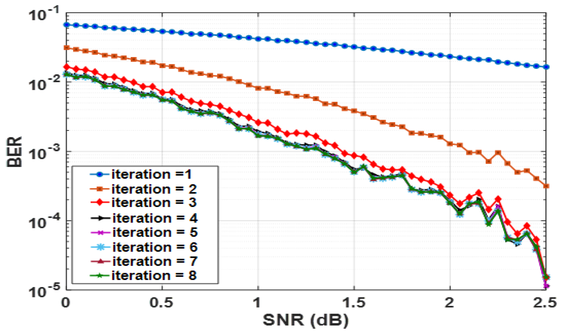
CTC decoding uses iterative decoding to exchange data between the protocol’s two decoder modules.
Figure 9 shows a BER for the CTC’s efficiency during decoder iterations one to eight. Increased decoding frequency improves the BER vs. SNR graphs. The number of rounds increases decoder communication, which helps CTC to fix faults.
TC’s error-correcting efficiency rises from one to two iterations. The decoders communicated and shared a lot of information throughout training. Hence, the receiver receives relevant input bits to accurately assess the situation. After a few cycles, the decoders may learn the input bits to anticipate. More iterations do not enhance decoder information sharing. Because of this, the BER performance only improved after the ninth decode cycle.
- (iii)
Effect of frame length of the CTC
What followed was a spectacular error-correcting performance [
26] from TC findings. Conclusions are drawn for frame lengths greater than 65,536 bits. Yet, frame lengths of around 1000 bits are required for video transmission. However, far shorter ones may be sufficient for uses such as voice transmission.
Figure 10 shows how well CTC works for error correction over a variety of frame durations. This process yielded the following sets of digits: 256, 508, 1020, 2048, and 65,536. Increasing the frame length improves the bit error rate performance, as seen in the
Figure 10, and this is particularly apparent at higher Signal-to-Noise Ratios. Increasing the frame length allows the CTC to generate more uncorrelated codewords and carry out efficient decoding due to the increased randomness in the interleaved sequence.
4.5. Effect of Signal-to-Noise Ratio on Image Quality
As a result of channel interference, the sent data is garbled. If there was severe bit corruption, the quality of the restored picture may be severely reduced. Moreover, if many bits are corrupted, it is possible that the correct secret information may be obtained incorrectly. Hence, we can examine the impact of channel noise on the picture quality achieved with CTC by graphing the CC and the PSNR with the Signal-to-Noise Ratio (SNR). The Signal-to-Noise Ratio (SNR) was improved from 0.0 to 1.0.
Figure 11a presents the results of plotting PSNR against SNR and CC against SNR. A picture of good quality will have a CC of at least 0.8 and a PSNR of at least 50 dB.
Figure 11b shows that at SNR values larger than 0.5 dB, the suggested CTC yields a CC of 1 and a PSNR of more than 50 dB. The research shows that the CTC can restore a high-quality picture to one that was previously distorted by noise of the same strength as the original signal (
Table 9,
Figure 12).
Table 10 provides a detailed breakdown of image quality characteristics for legitimate and illegitimate photo recovery. According to the findings, a real user can correctly recover the image with a correlation coefficient of nearly 1 and a Peak Signal-to-Noise Ratio (PSNR) of almost infinity, whereas a false user can only do so with a correlation coefficient of nearly 0 and a PSNR of less than 8 dB. The results ensure that an ordinary user may successfully recover the image, but a malevolent user is left with a severely altered version of the original, with a correlation coefficient of approximately 1 and a PSNR of 6.5326 roughly.
6. Limitations and Future Work
The suggested methods’ high operational complexity has two advantages: increased security and less time spent on encryption and decryption. A more likely outcome of a successful cryptanalysis was achieved by using an intermediate cypher. As can be seen from the above, not only do the suggested algorithms improve security, they also provide more robust security than the current methods. It has been shown that the suggested algorithms offer higher throughput than other encryption methods. It is also easy to show that our algorithms are safer than others due to the reduced likelihood of different assaults.
We combine mathematical techniques with those from the finite field GF( 7) to arrive at our conclusions. Prospective research has the potential to extend these findings beyond GF(2 n) and GF(3 n). Future work may expand these parameters to provide even more secure techniques; for now, we utilize a key length of 128 bits, a key matrix order of 4–6, and a Plaintext block size of 16–36 bytes. In this work, we establish the framework for future study by developing a novel method for Laplace transform-based data encryption and decryption utilizing polynomials of degree 8 or higher. Calculations grow more complex, and the key becomes longer and more obtuse, when a high-degree polynomial is used. In the future, similar studies may be conducted using a similar method with other integral transforms. Key matrices of orders 33 to 44 and Plaintext chunks of 9 bytes to 16 bytes are also used in the suggested techniques. Such details might be generalized in further research, allowing for the development of more sophisticated algorithms. The proposed methods make use of a Finite State Machine, a recurrence matrix, and the LU decomposition of a randomly selected non-singular matrix, together with key matrix orders of 44 and 55, key sizes of 128 and 200 bits, and block sizes of 16 and 25 bytes. By increasing the matrix size and the number of rounds, further research may make it possible to send more data safely in parallel. The resulting algorithms are more secure because of this and might potentially keep sensitive information hidden. The suggested works provide a novel encryption and decryption approach based on the Genetic Algorithm, making it exceedingly difficult to guess the key by combining a 128-bit key, a 4-by-4 key matrix, and a Plaintext block size of 16 bytes. More time will be spent theorizing on the Plaintext as a result of this.


 ,
, 


