Abstract
Beam models are widely applied in civil engineering, transport, and industry because the beams are basic structural elements. When dealing with the high-order modes of beam in the context of applying the modal analysis method, the numerical instability issue affects the numeric simulation accuracy in many boundary conditions. There are two solutions in literature to overcome this shortcoming, namely refinement of the asymptotic form for the high order modes and reshaping the terms within the equation of the modes to eliminate the source of the numerical instability. In this paper, the numerical instability issue is signalled when the standard form of Green’s function, which includes hyperbolic functions, is applied to a free-free Timoshenko length-long beam. A new way is proposed based on new set of eigenfunctions, including an exponential function, to construct a new form of Green’s function. To this end, it starts from a new general form of Green’s function and the characteristic equation is obtained; then, based on the boundary condition, the Green’s function associated to the differential operator of the free-free Timoshenko beam is distilled. The numerical stability of the new form of the Green’s function is verified in a numerical application and the results are compared with those obtained by using the standard form of the Green’s function.
Keywords:
Green’s function; hyperbolic function; exponential function; differential operator; numerical instability; free-free Timoshenko beam MSC:
35C15; 35Q74; 65L08
1. Introduction
Beams are structural elements characterized by the fact that the length is much higher than the cross-section dimensions and resist lateral loads. In addition to the cross-section shape and length, the beams are featured by the way they are supported at the ends, the equilibrium conditions, and the material from which they are made. Beams are extensively used in civil engineering, transport, and industry [1,2,3,4].
Several classical beam models are known that assume different mathematical forms depending on the working assumptions [5]. The Euler–Bernoulli model [6,7,8], the Rayleigh model [9,10], and the Timoshenko model [11,12] are mentioned. The Euler–Bernoulli model is the simplest because it considers only the bending deformation and the linear inertia. The Rayleigh model additionally introduces the rotation inertia and the Timoshenko model completes the beam model with the shear deformation. The Timoshenko model is a reliable model as it has been experimentally proven in many works, among which is ref. [13]. These models describe the propagation of bending waves through a beam with accuracy depending on the simplifications made. Thus, evanescent waves and propagating waves are highlighted. When the frequency of excitation is low, the wavelength of the propagating wave is much longer than the characteristic dimension of the cross-section of the beam, namely the radius of gyration, and the solutions given by the above models are convergent. For a high frequency of the excitation, the influence of the shear deformation and the inertia of the cross-section rotation becomes significant, and that is why the more accurate predictions are obtained using the Timoshenko model.
Moreover, also at high frequency, there are differences between the models in terms of the type of bending waves propagating along the beam. While the Euler–Bernoulli beam model shows the coexistence of evanescent and propagating waves regardless of the excitation frequency, the Timoshenko model predicts the transformation of evanescent waves into propagating waves if the frequency exceeds a certain value. The Timoshenko beam is said to have two spectra. The first spectrum is like that of the Euler–Bernoulli beam in the sense that evanescent and propagating waves coexist, and the second spectrum is characterized by the fact that two propagating waves with different wavelengths propagate through the beam.
The differential equations of motion of the beam models can be solved by several methods, including the following: the modal analysis method by which the response of the beam is the result of the superposition of its natural vibration modes [8,14,15]; the direct method where the input force is included in the boundary condition for the problem [6,16,17]; and the Green’s function method, which represents the frequency response to a unitary harmonic force (receptance), and the vibration is obtained by applying the convolution theorem [12,18,19,20].
The successful application of one or another of the methods for solving the differential equations of motion depends, among other things, on its numerical stability in the sense that the results must not be affected by substantial floating-point errors [21,22,23,24].
Numerical instability is related to the calculation in floating point when the small difference between two very large numbers is calculated. Numerical calculation in floating point is zero instead of a small, but significant number. Such situations were reported when numerical evaluation of the high-mode shapes of Euler–Bernoulli and Timoshenko uniform or stepped beams were performed to apply the modal analysis method [21,22,23,24,25,26,27].
The usual form of the mode shapes derived from the differential operators that describe the vibration of a beam depending on the boundary conditions is constructed using the pairs of trigonometric and hyperbolic functions: sine and cosine; and hyperbolic sine and hyperbolic cosine, respectively. The trigonometric functions describe the propagation of propagating waves, and the hyperbolic ones describe the propagation of evanescent waves.
The use of hyperbolic functions can lead to the numerically unstable shape
where kd is the attenuation constant of the evanescent wave, and x, the coordinate of the beam. When the argument of the function E(x) is large enough, the result of the calculation in floating point is zero.
For instance, the modal shape of the n order of a free-free Euler–Bernoulli beam can be written as [28]
where l is the beam length and knl verifies the characteristic equation
It should be noted that for the Euler–Bernoulli beam model, the attenuation constant of the evanescent wave equals the wave number of the propagative wave and because of that, the trigonometric functions and the hyperbolic functions have the same arguments (knx or knl).
Figure 1 shows the modal shape for n = 10, 11, and 14, which has been calculated using the MATLAB environment of ordinary precision. It is observed that while the modal shape of the 11th order is affected at the beam end by the numerical instability, the modal shape of the 10th order is still calculated within an acceptable margin of error. When the order of the modal shape is higher, for instance, n = 14, the numerical calculation exhibits zero value because the modal shape is reduced to Equation (1) from a numerical viewpoint. A similar result has been reported in ref. [24]; however, this is for a clamped-clamped Euler–Bernoulli beam.
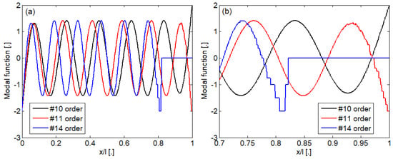
Figure 1.
Illustrative for the numerically instability of the modal shape of a free-free Euler–Bernoulli beam: (a) full modal shape; (b) detail.
Two different solutions have been advanced: the construction of an asymptotic form for the high-order modes [25,27] and the restructuration of the equation of the modes to eliminate the source of the numerical instability [21,22,23,24,26].
In this paper, it is shown that the application of the Green’s function method can be affected by the problem of numerical instability, taking as an example the vibration of a free-free Timoshenko beam. The standard form of the Green’s function includes the hyperbolic sine and cosine functions, which model the evanescent waves whose existence is specific to the first spectrum; in addition, because of this, the calculated spectrum experiences distortions at medium frequencies in the case of long-length beams. It has been demonstrated that the numerical instability starts from the middle of the frequency range of the first spectrum and advances to both its ends as the beam length increases. To overcome this problem, a new approach is proposed which starts from a new basis in the solutions space of the differential operator of the Timoshenko beam, namely a new set of eigenfunctions including the exponential function of a positive and negative real argument to model the evanescent waves. By imposing the specific boundary conditions of the Timoshenko beam, a new form of the Green’s function is constructed, which proves to be numerically stable in the case of long-length beams.
2. Mechanical Model and Equations of Motion
Let us consider a uniform Timoshenko beam of length l under the action of a time-dependent transversal force (Figure 2). Parameters of the beam are as follows: Young’s modulus E, the shear modulus G, the density ρ, the mass per length unit m, the cross-section area S, the area moment of inertia I, and the shear coefficient κ.
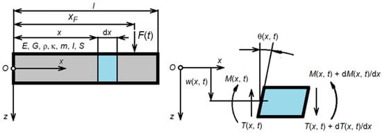
Figure 2.
Mechanical model of the free-free Timoshenko beam.
Equations of motion describing the bending motion of the beam can be written as:
where w(x, t) and θ(x, t) are the displacement and rotation of the cross-section of the beam; F(t) is the transversal force, and xF—the distance between the reference frame Oxz fixed at the left end of the beam and the active cross-section where the force is applied; t stands for the time and x stands for the coordinate along the beam; and, in the following, it defines the passive cross-section where the beam response is calculated.
Boundary conditions associated to the free-free beam refer to the shear force T(x, t) and the bending moment M(x, t):
which must be zero at the beam ends
Considering the steady-state harmonic behaviour, the following complex variables can be introduced:
where , , and are the complex amplitudes; ω is the ungular frequency; and i2 = −1. Appendix A presents the reason behind Equation (7).
Inserting the complex variables (7) in the equations of motion (4), it obtains
Boundary conditions (6) take the following form:
Eliminating the angle of rotation of the cross-section in (8), the following equation in the displacement of the beam results:
where DT is the differential operator
The corresponding boundary conditions associated to Equation (10), which are derived from Equation (9), are
where
In the next section, the solution to the differential equations (10) and the corresponding boundary conditions (12) is expressed in terms of Green’s functions associated to the DT operator.
3. Green’s Functions Method
Green’s function of the DT differential operator verifies the equation
and the boundary conditions derived from Equation (12)
Green’s function is a linear combination of the eigenfunctions of that operator and to find these eigenfunctions, the starting point is the homogeneous equation derived from Equation (14)
seeking the solutions of the following form
where A(ξ) is a function depending on the boundary conditions, and k is a complex parameter.
Inserting the form (17) in Equation (16), the characteristic equation of the DT differential operator results:
where
is the wavenumber of the Euler–Bernoulli beam.
Solutions of the characteristic equation are the eigenvalues of the DT differential operator, and their nature are depending on the angular frequency ω. Considering the first spectrum of the beam meaning
the eigenvalues take the forms ±kd and ±ikp, where
Appendix B gives the details of the calculation regarding Equation (21).
It should be mentioned that the eigenvalues are the propagation constants of the waves that travel in the Timoshenko beam, namely kd is for the evanescent waves and ikp is for the propagative waves. The minus sign indicates the progressive waves and the plus sign is associated to the regressive waves.
Figure 3 presents the propagation constant of the evanescent wave, kd, and the imaginary part of the propagation constant of the propagative wave, kp, versus the angular frequency within the frequency range of the first spectrum. While kp increases monotonically from zero, the propagation constant kd has an increasing–decreasing pattern with a maximum, max(kd), at the angular frequency ωo and a zero at ωlim.
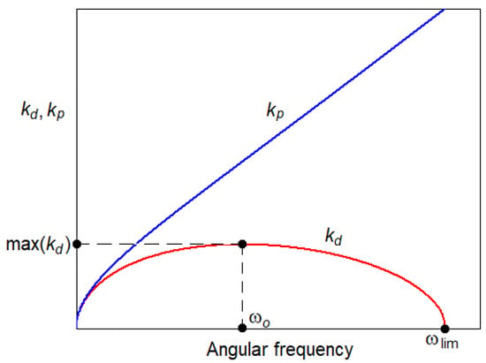
Figure 3.
Propagation constants of the Timoshenko beam.
The angular frequency ωo is obtained from the equation
After a few calculations detailed in Appendix C, the form is arrived at
By searching for the positive solutions, the angular frequency corresponding to the maximum value of kd is reached
which is close to the middle of the spectrum; E, G, and κ are constants of material and the denominator E − Gκ is positive.
Maximum value of kd results:
where
Corresponding to the above eigenvalues, the eigenfunctions usually used to construct Green’s functions are [29]:
Instead of the hyperbolic functions, the exponential functions are considered for Green’s function, which can be written as
Green’s function and the first two derivatives are continuous functions for x = ξ, and the third derivative experiences a discontinuity of 1/(EI) magnitude
The above-mentioned conditions lead to the following matrix equation:
where
The solution to the matrix Equation (30) holds
where
Using relations (28) and (32), Green’s function becomes
where H(.) is the Heaviside step function.
Imposing that the Green’s function checks the boundary conditions (15), the functions Ai(ξ) can be calculated.
Inserting (34) in the boundary conditions for the beam displacement (15), it holds
where
Solving the set of Equation (35), it results
where
It should be outlined that the equation
is the characteristic equation and gives the natural frequencies of the free-free Timoshenko beam. This form is termed as a numerically stable form of the characteristic equation.
Green’s function for the beam displacement is
where
However, the Green’s function is symmetric due to the Maxwell-Betti theorem
and in virtue of this fact, the Green’s function can be calculated as
In addition, for 0 < ξ < x < l, the Green’s function Gw(x, ξ) equals Gw(ξ, x) calculated with the above relation.
In the following lines, this function is termed as the numerically stable form of the Green’s function associated to the DT differential operator and the F-F boundary conditions.
Indeed, examining the shape of functions Φ1(ξ), Φ2(ξ), and Φ*1(ξ, x), corresponding to Equations (39), (40), and (43), respectively, which are included in the Equation (45) of Green’s function, no numerically unstable shape appears; and all the terms containing kdl and kd(ξ − x) are decreasing exponentials as l and (ξ − x) are increasing, assuring the numerical stability of Green’s function.
The solution to Equation (10) can be given in terms of the convolution theorem
where is Green’s function of the beam displacement to a transversal force, the so-called receptance
Starting from the eigenfunctions (27) and following the same way as above, the standard form of Green’s function of the DT differential operator and F-F boundary conditions comes first
where
and
gives the standard form of the characteristic equation
Then, Green’s function of the beam displacement due to a transversal force
holds in the standard form. Equation (51) is equivalent to Equation (20) from ref. [28] and Equation (53) is an alternative to Equation (15) from the same reference.
4. Numerical Application
In this section, the results from some numerical applications are presented to illustrate the effectivity of the numerically stable form of the frequency-domain Green’s function of the free-free uniform Timoshenko beam described in the above section. To this end, the following parameters of the Timoshenko beam are considered: E = 210 GPa, G = 8.08 GPa, κ = 0.4, ρ = 7850 kg/m3, S = 7.69∙10−3 m2, and I = 30.55∙10−6 m4. These parameter values correspond to the UIC 60 rail type, extensively used in the modern railway tracks. The frequency range of interest is the first spectrum that is discretized by a step of 0.01 Hz. The limit frequency of the first spectrum is given by Equation (20) and for the numerical application, takes the value of 5123.6 Hz. All the calculations are performed using the MATLAB environment with regular precision.
Figure 4 shows the graphic of the Δ and Δst functions calculated with Equations (38) and (51); and considering the beam length of 1 m. The standard form Δst has a sharply modulated form; meanwhile, the numerically stable form Δ takes an almost harmonic shape. However, there is a perfect match between the zeros of these two forms. The natural frequencies of the beam are at: 956.3 Hz, 2022 Hz, 3144 Hz, 4147 Hz, and 5115 Hz.
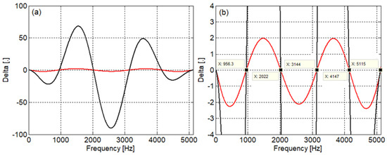
Figure 4.
Determination of the natural frequencies of the free-free Timoshenko beam (l = 1 m): (a) graphic of Δ and Δst; (b) detail; ──, numerically stable form (Equation (38)); ──, standard form (Equation (51)).
Figure 5 represents the modulus of the beam receptance calculated using both numerically stable and standard forms at the middle (x = l/2) and at the first quarter (x = l/4) of the beam when the active cross-section is at middle (ξ = l/2) for the same beam length of 1 m; in addition, Figure 6 displays the modulus of the beam receptance at the middle and at the first third of the beam (x = l/3) when ξ = l/3. Generally speaking, the beam vibration is the result of the superposition of the symmetric and antisymmetric modes. When the active cross-section is at the beam middle, only the symmetric modes are excited, which explain why the beam receptance within the two diagrams exhibits peaks at three of the five resonance frequencies as can be seen in Figure 5. On the other hand, both symmetric and antisymmetric modes are excited when the active cross-section is situated in any other section excepting the one from the beam middle. This situation is illustrated in Figure 6, where the receptance at the first third has five peaks. However, at the beam middle, only the symmetric modes can be detected because this section is a node for any antisymmetric mode. Regarding the accuracy of the calculus, both forms give similar results as can be seen in the two figures.
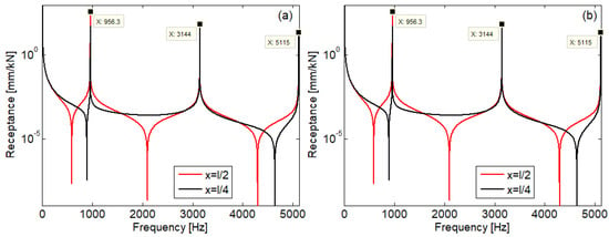
Figure 5.
Beam receptance modulus when the active cross-section is at the beam middle (ξ = l/2): (a) numerically stable form; (b) standard form.

Figure 6.
Beam receptance modulus when the active cross-section is at the first third (ξ = l/3): (a) numerically stable form; (b) standard form.
In spite of that, closer calculation shows the errors that appear between the results given by the two forms of Green’s function. Thus, Figure 7 and Figure 8 present the absolute values of the relative errors calculated in relation to the receptance obtained with the numerically stable form

Figure 7.
Errors between the results given by the two forms when the active cross-section is at the beam middle (ξ = l/2): (a) for receptance at the beam middle; (b) for receptance at the first quarter.

Figure 8.
Errors between the receptances calculated by the two forms when the active cross-section is at the first third (ξ = l/3): (a) for receptance at the beam middle; (b) for receptance at the first third.
The errors are very low within the entire frequency range of the first spectrum. Relatively more high values can be observed around the resonance and anti-resonance frequencies; however, these are insignificant, being less than 8.2·10−8%.
As the beam length increases, the first spectrum becomes richer in harmonics components as can be seen in Figure 9, where the beam receptance was calculated following the same conditions as above (ξ = l/2, and x = l/2 and l/4; and ξ = l/3, and x = l/2 and l/3). Calculation was performed using the numerically stable form of Green’s function for a beam of 20 m length. Features like those highlighted in the case of the 1 m length beam can be outlined: only the symmetrical vibration modes of the beam are excited by the harmonic force applied at the beam middle (diagrams (a) and (b)); and the middle of the beam experiences only symmetrical vibration modes regardless of the section in which the excitation force acts (diagram (c)).

Figure 9.
Beam receptance modulus of a 20 m length beam calculated using the numerically stable form of the Green’s function: (a) ξ = l/2 and x = l/2; (b) ξ = l/2 and x = l/4; (c) ξ = l/3 and x = l/2; (d) ξ = l/3 and x = l/3.
When the standard form of Green’s function is used to calculate the beam receptance, the results that are displayed in Figure 10 show numerical instability issues. Receptance calculation is affected by numerical instability mainly when the active cross-section and passive cross-section are identical, especially at the middle of the beam. Indeed, for a beam of a given length l that experiences numerical instability, the most affected component of the frequency response is the one for which kdl = max(kdl) = lmax(kd) and whose angular frequency is ωo, which is found near the middle of the domain of the first spectrum (see Figure 3). For the numerical application, fo = ωo/(2π) = 2304.9 Hz, which represents 89.97% of half of the limit frequency of 5123.6 Hz.
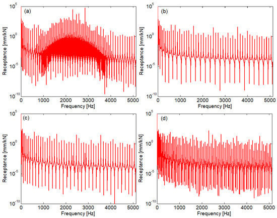
Figure 10.
Beam receptance modulus of a 20 m length beam calculated using the standard form of Green’s function: (a) ξ = l/2 and x = l/2; (b) ξ = l/2 and x = l/4 ; (c) ξ = l/3 and x = l/2; (d) ξ = l/3 and x = l/3.
The magnitude of the errors induced by the numerical instability of the standard form of Green’s function can be evaluated following Figure 11. For all the cases examined, errors are very low at the ends of the spectrum; however, they take huge values at the middle frequency.
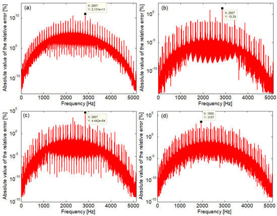
Figure 11.
Relative errors between the results obtained with the two forms of Green’s function for a 20 m length beam: (a) ξ = l/2 and x = l/2; (b) ξ = l/2 and x = l/4; (c) ξ = l/3 and x = l/2; (d) ξ = l/3 and x = l/3.
5. Discussion
In this section, some aspects about the concerns regarding the numerical application of the new form of Green’s function of a long-length free-free Timoshenko beam are presented.
The critical parameter of Green’s function from a numerical calculation viewpoint is the beam length, l; and it has been shown what happens when the standard Green’s function is calculated for a long-length beam in the previous section.
Applying the new form of Green’s function, much attention must be paid to the partition step applied to the frequency domain of the first spectrum. If the step length is too large, then the accuracy of the calculation suffers, and the peaks of resonance and anti-resonance are missing. This aspect is illustrated in Figure 12, which shows the receptance modulus of a 100,000 m length beam calculated applying the numerically stable form of Green’s function (ξ = l/3, and x = l/2 and l/3). Figure 12a is obtained using the frequency partition step of 10 mHz, as used in the previous simulations. Figure 12b shows the receptance modulus of the beam when the step of the frequency partition is much finer, namely 10 μHz. The difference is very clear.
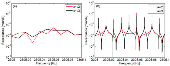
Figure 12.
Beam receptance modulus of a 100,000 m length beam calculated using the numerically stable form of the Green’s function (ξ = l/3): (a) Δf = 10 mHz; (b) Δf = 10 μHz.
Obviously, the simulation time increases when the first spectrum of very long-length beams is investigated.
It has to be noticed that for such a long beam, the standard Green’s function does not work at all, and the result is NaN (not a number).
6. Conclusions
Studying beams dynamics is very important as the beams are basis components in mechanical structures. Several beam models are known; however, the most frequently used are the Euler–Bernoulli model and the Timoshenko model. The latter ensures the accuracy of theoretical predictions over an extended frequency range because the effect of the shear force on the rotation of the cross-sections and upon the rotary inertia is included. Among the methods of studying the dynamics of beams, the modal analysis method and Green’s function method can be listed. It is known that the application of modal analysis for higher modes of vibration presents difficulties caused by numerical instability.
In this paper, it was shown that the standard form of the Green’s function associated to the free-free Timoshenko beam built based on the hyperbolic sine and cosine functions presents the same difficulty related to the numerical instability when dealing with long-length beams. This is manifested primarily in the field of medium frequencies by the spectacular distortion of the beam’s frequency response, which spreads toward the spectrum ends as the length beam increases, but never reaching them. For this reason, it is not recommended to use the standard form of the Green’s function for the analysis of long-length beams. On the other hand, it was shown that this difficulty can be overcome if the Green’s function is built based on the exponential function. The new numerically stable form of Green’s function for the free-free Timoshenko beam model was deduced and its effectiveness was shown over the entire frequency range of the first spectrum.
Further research aims to determine the numerically stable form of the Green’s function for the usual end-resting cases.
Funding
This work was supported by a grant of the Ministry of Research, Innovation and Digitization, CCCDI-UEFISCDI, project number PN-III-P2-2.1-PED-2021-0601, within PNCDI III.
Data Availability Statement
Not applicable.
Conflicts of Interest
The author declares no conflict of interest.
Appendix A
In this section, the introduction of the complex variables in Equation (7) is justified.
The exponential function in Equation (7) describes the steady-state harmonic behavior, which means that both the transversal force and beam motion are of harmonic shape:
where F, w(x), and θ(x) are amplitudes; ϕw(x) and ϕθ(x) are the out of phases in respect of the force; and ω is the angular frequency. All these quantities are represented by real numbers, and verify the equations of motion (4) and the boundary conditions (6).
Using the Euler formula for the exponential function,
the real quantities can be replaced by the complex quantities as defined in Equation (7):
where the complex amplitudes include the out of phase of the real quantities
Real quantities are a real part of the complex quantities, the real amplitudes are the modulus of the complex amplitudes, and the arguments of the complex amplitudes equals the out of phases:
On the other hand, the imaginary part of the complex quantities (A3) verify the equations of motion (4) and the boundary conditions (6) because the imaginary parts and the real parts are in quadrature.
By virtue of the above, the complex quantities (A3) verify the equations of motion (4) and the boundary conditions (6), and Equations (8) and (9) hold.
Appendix B
In this section, the details regarding the calculation of Equation (21) are shown.
Equation (21) refers to the eigenvalues ±kd and ±ikp, which are the solutions of the characteristic Equation (18)
It obtains
Imposing and using Equation (13),
Equation (19),
and
it writes
which means the condition (20),
and holds
m = ρS,
Setting
it obtains the following forms of the four solutions of the equation characteristic
Finally, Equation (21) results:
Appendix C
In this section, the calculation steps are presented to obtain Equation (23).
First, the derivate of kd with respect to ω is
where
where
and
Inserting Equations (A18), (A19), (A20), and (A22) in Equation (A17), it holds
Equation (20) is equivalent to
Inserting kl, ks, and kE−B,
in Equation (A24), it obtains
Considering Equation (A21), Equation (A26) becomes
Seeking a solution different to zero, the following equation holds:
The radical term is isolated
and then, both members are squared
and the terms are regrouped
After the minor algebraic calculation, Equation (20) results:
References
- Vieira, L.; Gonçalves, R.; Dinar Camotim, D.; Pedro, J.O. Generalized Beam Theory deformation modes for steel–concrete composite bridge decks including shear connection flexibility. Thin-Walled Struct. 2021, 169, 108408. [Google Scholar] [CrossRef]
- Zhang, X.; Thompson, D.; Sheng, X. Differences between Euler-Bernoulli and Timoshenko beam formulations for calculating the effects of moving loads on a periodically supported beam. J. Sound Vib. 2020, 481, 115432. [Google Scholar] [CrossRef]
- Pai, P.F.; Qian, X.; Du, X. Modeling and dynamic characteristics of spinning Rayleigh beams. Int. J. Mech. Sci. 2013, 68, 291–303. [Google Scholar]
- Mutlak, D.A.; Muhsen, S.; Waleed, I.; Hadrawi, S.K.; Khaddour, M.H.; Ahmadi, S. Forced and free dynamic responses of functionally graded porous Rayleigh small-scale beams on Kerr foundation under moving force. Mater. Today Commun. 2022, 33, 104919. [Google Scholar] [CrossRef]
- Han, S.; Benaroya, H.; Wei, T. Dynamics of transversely vibrating beams using four engineering theories. J. Sound Vib. 1999, 225, 935–988. [Google Scholar] [CrossRef]
- Mazilu, T.; Leu, M.C. On the modelling of rail joint. Mater. Sci. Forum 2019, 957, 22–42. [Google Scholar] [CrossRef]
- Baysal, O.; Hasanov, A. Solvability of the clamped Euler–Bernoulli beam equation. Appl. Math. Lett. 2019, 93, 85–90. [Google Scholar] [CrossRef]
- Dumitriu, M. A new passive approach to reducing the carbody vertical bending vibration of railway vehicles. Veh. Syst. Dyn. 2017, 55, 1787–1806. [Google Scholar] [CrossRef]
- Ebrahimi-Mamaghani, A.; Sarparast, H.; Rezaei, M. On the vibrations of axially graded Rayleigh beams under a moving load. Appl. Math. Modell. 2020, 84, 554–570. [Google Scholar] [CrossRef]
- Aouadi, M.A.; Lakrad, F. On mathematical modelling of linear flexural vibrations of spinning Rayleigh beams. J. Sound Vib. 2018, 430, 17–35. [Google Scholar] [CrossRef]
- Zhao, X.; Chen, B.; Li, Y.H.; Zhu, W.D.; Nkiegaing, F.J.; Shao, Y.B. Forced vibration analysis of Timoshenko double-beam system under compressive axial load by means of Green’s functions. J. Sound Vib. 2020, 464, 115001. [Google Scholar] [CrossRef]
- Mazilu, T.; Dumitriu, M.; Tudorache, C.; Sebeșan., M. Using the Green’s functions method to study wheelset/ballasted track vertical interaction. Math. Comput. Modell. 2011, 54, 261–279. [Google Scholar] [CrossRef]
- Díaz-de-Anda, A.; Flores, J.; Gutiérrez, L.; Méndez-Sánchez, R.A.; Monsivais, G.; Morales, A. Experimental study of the Timoshenko beam theory predictions. J. Sound Vib. 2012, 331, 5732–5744. [Google Scholar] [CrossRef]
- Giunta, F.; Cicirello, A. On the analysis of jointed Euler-Bernoulli beams with step changes in material and cross-section under static and dynamic loads. Eng. Struct. 2019, 179, 66–78. [Google Scholar] [CrossRef]
- Zhou, J.; Goodall, R.; Ren, L.; Zhang, H. Influences of car body vertical flexibility on ride quality of passenger railway vehicles. Proc. Inst. Mech. Eng. Part F J. Rail Rapid Transit 2009, 223, 461–471. [Google Scholar] [CrossRef]
- Mazilu, T. The dynamics of an infinite uniform Euler-Bernoulli beam on bilinear viscoelastic foundation under moving loads. Procedia Eng. 2017, 199, 2561–2566. [Google Scholar] [CrossRef]
- Hussein, M.F.M.; Hunt, H.E.M. Modelling of floating-slab tracks with continuous slabs under oscillating moving loads. J.Sound Vib. 2006, 297, 37–54. [Google Scholar] [CrossRef]
- Kukla, S.; Zamojska, I. Frequency analysis of axially loaded stepped beams by Green’s function method. J. Sound Vib. 2007, 300, 1034–1041. [Google Scholar] [CrossRef]
- Han, H.; Cao, D.; Liu, L. Green’s functions for forced vibration analysis of bending-torsion coupled Timoshenko beam. Appl. Math. Model. 2017, 45, 621–635. [Google Scholar] [CrossRef]
- Tang, L.; Yu, L.; Wang, M.; Li, Z.; Zhang, X.; Lu, M.; Yang, H. Green’s functions based on the Timoshenko beam model for the longitudinal seismic dynamic response of tunnels crossing soft and hard rock strata. Tunnelling and Underground Space Technology 2022, 128, 104545. [Google Scholar] [CrossRef]
- Shankar, K.; Keane, A.J. Energy flow predictions in a structure of rigidly joined beams using receptance theory. J. Sound Vib. 1995, 185, 867–890. [Google Scholar] [CrossRef]
- Gonçalves, P.J.P.; Brennan, M.J.; Elliot, S. Numerical evaluation of high-order modes of vibration in uniform Euler–Bernoulli beams. J. Sound Vib. 2007, 301, 1035–1039. [Google Scholar] [CrossRef]
- Gonçalves, P.J.P.; Peplow, A.; Brennan, M.J. Exact expressions for numerical evaluation of high order modes of vibration in uniform Euler-Bernoulli beams. Appl. Acoust. 2018, 141, 371–373. [Google Scholar] [CrossRef]
- Khasawneh, F.; Segalman, D. Exact and numerically stable expressions for Euler-Bernoulli and Timoshenko beam modes. Applied Acoustics 2019, 151, 215–228. [Google Scholar] [CrossRef]
- Dowell, E.H. On asymptotic approximations to beam model shapes. J. Appl. Mech. 1984, 51, 439. [Google Scholar] [CrossRef]
- Tang, Y. Numerical evaluation of uniform beam modes. J. Eng. Mech. 2003, 129, 1475–1477. [Google Scholar] [CrossRef]
- Van Rensburg, N.; Van der Merwe, A. Natural frequencies and modes of a Timoshenko beam. Wave Motion 2006, 44, 58–69. [Google Scholar] [CrossRef]
- Shabana, A.A. Theory of Vibration Volume II: Discrete and Continuous Systems; Springer: New York, NY, USA, 1991; p. 200. [Google Scholar]
- Lueschen, G.G.G.; Bergman, L.A. Green’s functions for uniform Timoshenko beams. J. Sound Vib. 1996, 194, 93–102. [Google Scholar] [CrossRef]
Disclaimer/Publisher’s Note: The statements, opinions and data contained in all publications are solely those of the individual author(s) and contributor(s) and not of MDPI and/or the editor(s). MDPI and/or the editor(s) disclaim responsibility for any injury to people or property resulting from any ideas, methods, instructions or products referred to in the content. |
© 2022 by the author. Licensee MDPI, Basel, Switzerland. This article is an open access article distributed under the terms and conditions of the Creative Commons Attribution (CC BY) license (https://creativecommons.org/licenses/by/4.0/).