Article

Three-Stage-Impulse Control of Memristor-Based Chen Hyper-Chaotic System

1
School of Electronic and Information Engineering, Chongqing Three Gorges University, Wanzhou, Chongqing 404100, China
2
Australian AI Institute, University of Technology Sydney, Ultimo, NSW 2007, Australia
3
Chongqing Engineering Research Center of Internet of Things and Intelligent Control Technology, Chongqing Three Gorges University, Wanzhou, Chongqing 404100, China
4
Department of Mathematics, University of Ibadan, Ibadan 200005, Nigeria
*
Author to whom correspondence should be addressed.
Mathematics 2022, 10(23), 4560; https://doi.org/10.3390/math10234560
Submission received: 27 October 2022 / Revised: 25 November 2022 / Accepted: 28 November 2022 / Published: 1 December 2022

Abstract

:
In this paper, on the basis of the three-dimensional Chen system, a smooth continuous nonlinear flux-controlled memristor model is used as the positive feedback term of this system, a hyper-chaotic circuit system is successfully constructed, and a simulated equivalent circuit is built for simulation using Multisim software, which agrees with the numerical simulation results by comparison. Meanwhile, a new impulsive control mode called the three-stage-impulse is put forward. It is a cyclic system with three components: continuous inputs are exerted in the first and third parts of the cycle while giving no input in the second part of the cycle, an impulse is exerted at the end of each continuous subsystem, the controller is simple in structure and effective in stabilizing most existing nonlinear systems. The Chen hyper-chaotic system will be controlled based on the three-stage-impulse control method combined with the Lyapunov stability principle. At the end of this paper, we have employed and simulated a numerical example; the experimental results show that the controller is effective for controlling and stabilizing the newly designed hyper-chaotic system.

1. Introduction

The mystery of the chaos phenomenon was unveiled in the late 19th century when French mathematician Poincaré studied the three-body problem, and in 1963 when meteorologist Lorenz proposed the classical Lorenz system in his study of meteorological changes [1], which kicked off the study of the chaos phenomenon and chaos theory. Chen used linear feedback methods to control the Lorenz system and discovered the famous Chen system [2] in 2000, which is similar to the Lorenz system but has a richer dynamical behavior. Compared with chaotic systems, hyper-chaotic systems have more complex attractor structures and richer dynamical behaviors. Many scholars construct hyper-chaotic systems by adding feedback terms to continuous systems to increase the complexity of the system [3,4,5,6]. In [3], a linear feedback term is introduced into a continuous system with two two-wing attractors to construct a four-wing hyper-chaotic system, which is verified by numerical simulations and circuit experiments. In [5], using the state feedback control technique, two nonlinear functions are introduced as feedback terms into the modified Sportt B system, and hyper-chaotic systems with lattice multi-wing hidden attractors are successfully constructed.
The definition of the memristor was proposed by Chua [7] in 1971, and it was realized by the Hewlett-Packard [8] research team in 2008. The memristor got its name from the dependence of its resistance on the amount of electricity passing through it. The memristor has nonlinear characteristics, which can be applied to circuit designs to generate chaotic signals with more complex dynamic behaviors. From the existing research, there are three methods to construct memrisive chaotic systems: (i) The memrisive chaotic circuit is directly composed of four basic circuit elements: resistor, capacitor, inductor, and memristor; (ii) Based on the nonlinear characteristics of memristors, the nonlinear components in chaotic circuits are replaced by memristors; (iii) Constructing a new chaotic system using memristor as the feedback term of an existing chaotic system.
The first approach is taken in [9], which constructs a memristor-based chaotic circuit based on three basic circuit elements (capacitor, inductor, and memristor) and applies the complex, chaotic signals generated by the chaotic circuit to secure communications. In [10], a series of nonlinear oscillators were obtained by replacing Chua’s diodes with a memristor, which is the first report on the combination of a memristor and chaotic circuits. On the basis of the existing three-dimensional chaotic system, the memristor is used to replace the coupling resistor in [11], and a memrisive hyper-chaotic system with an infinite number of hidden attractors is obtained. In recent years, with the research boom of memristors, many classical chaotic systems have been successfully improved into memrisive chaotic systems with research value by combining with memristors [12,13,14,15]. In [14], by introducing the memristor as a feedback term in the Liu–Chen system, a four-wing memristor chaotic system with extreme multi-stability is obtained, which further reveals the complex phenomenon of memristor chaos with infinite equilibrium points. The method adopted in this paper is the last one. On the basis of the classical Chen chaotic system, the memristor is used as a positive feedback term to successfully construct a hyper-chaotic system based on a memristor. For the Chen system, the use of a memristor as nonlinear feedback to generate a hyper-chaotic phenomenon is much less difficult to implement due to the high memory capacity of the memristor for the current flowing through it. At the same time, the application of memristors to chaotic systems has become a new research hotspot, and a lot of research results have been achieved in recent years [16,17,18,19,20,21,22].
Over the past few decades, the control of chaotic systems has received great attention and has been applied to many fields, such as physics, fluid dynamics, nonlinear circuits, neural networks, and biomedicine. Meanwhile, some useful and very efficient control methods have been proposed, and these methods may include adaptive control [23,24,25,26], sliding mode control [27,28], synchronization [29,30,31,32,33,34], impulsive control [35,36,37,38], etc. In practice, some parameters of chaotic systems may be unknown. A four-dimensional hyper-chaotic system is proposed in [23], and an adaptive control law is designed to stabilize the four-dimensional hyper-chaotic system with unknown parameters by combining Lyapunov stability and adaptive control theory. There are external disturbances and uncertainties when various real-time control systems are controlled. A new robust controller is proposed in [27], which takes into account external disturbances and uncertainties and can stabilize a fourth-order chaotic system in finite time with only one control input. Ref. [29] considers the effect of actuator saturation and proposes an optimization method to design synchronous controllers with actuator saturation. However, Ref. [29] assumes that the saturation function is symmetric with respect to the original definition, and, in practice, asymmetry in saturation is very common. Ref. [30] proposes an asymmetric saturated impulsive synchronization control scheme for the synchronization of nonlinear dynamic systems. Meanwhile, the stability problem of neural networks has also gained attention in recent years, triggering a series of studies. Ref. [33] investigates the synchronization problem of coupled neural networks with mixed delays, switching topologies, and random perturbations; the difficulties caused by unbounded distribution delays and random perturbations are solved. The study of the stability of discrete systems is challenging; Ref. [34] considers not only the perturbation problems that occur in real situations but also the possibility of actuator failures and investigates the global exponential synchronization problem for a class of switching discrete-time neural networks. Compared with the above control methods, impulsive control is widely used in control theory because of its simple structure and obvious effect. Ref. [35] considers the state problem of an unknown system and uses uncertain pulses to stabilize the nonlinear system. In many cases, there is a time delay in the system, which leads to some instability. Ref. [36] analyzes the stability of time-lag systems with impulse control and proposes an inequality with delayed impulses, which facilitates the analysis of time-lag systems.
Compared with the above-mentioned literature, the controller proposed in this paper is simple in structure and effective in method and can be applied to most existing nonlinear dynamic systems. In this paper, the method employed combines the switching control with impulses [39] and finally designs a three-stage-impulse control system with a sandwich controller to stabilize the memristor-based Chen hyper-chaotic system. A period of the system is divided into three parts. A continuous control k 1 y ( t ) is exerted in the first part of the period and immediately exerts an impulse J 1 at the end of k 1 y ( t ) . The system has no external input in the second part of the period, and another impulse, J 2 is exerted at the end of the second part. Similarly, a continuous input k 2 y ( t ) is exerted in the third part of the system. Three impulses are exerted in one period of this system, called three-stage-impulse. Figure 1 explains the fundamentals of the three-stage-impulse control systems.
Considering all of these cases, the main contributions of this paper are listed as follows:
(i)
The memrisive hyper-chaotic system is successfully constructed, and the results of numerical simulation and circuit simulation are basically consistent;
(ii)
The modular design of the system circuit is simple, using relatively few components, and the circuit parameters can be determined directly;
(iii)
A new control scheme is proposed that can be extended to other nonlinear systems.
The remaining parts of this paper are divided into the following sections: in Section 2, a new hyper-chaotic system based on memristor feedback is given, along with a mathematical model and circuit implementation diagram; in Section 3, a model of the nonlinear control system with three-stage-impulse scheme is described, and some preliminary results are presented; in Section 4, a theorem for proving the exponential stability of systems at the origin, their effectiveness, and feasibility using the conditions of the linear matrix inequality are given; in Section 5, an impulsive control law is devised to stabilize the new Chen hyper-chaotic system, and the numerical simulation is also given. Section 6 contains the summary and the conclusion of the article.
Notation 1.
The following symbols are used in this paper. R n denotes the n-dimensional real spaces; R n × m denotes the n × m matrices, where n and m are positive integers. The superscript “T” denotes the transpose of the matrix, λ D ( Λ ) and λ X ( Λ ) , respectively, denote the maximal and minimal eigenvalue of square matrix Λ. I denotes the identity matrix, and | | y | | denotes the Euclidean norm of vector y.

2. Formulation of a New Memristor-Based Hyper-Chaotic System

The mathematical model of the Chen system is given by the following set of differential equations [2],
x ˙ = a ( y x ) , y ˙ = ( c a ) x x z + c y , z ˙ = x y b z ,
where x, y, and z are the state variables of the system, and a, b, and c are real parameters. The chaotic system can be implemented using an analog-integrated operational amplifier and multiplier; a modular circuit design for the Chen system of this model is shown in Figure 2.
A nonlinear feedback term is added to the system to improve the complexity and unpredictability of the system. Thus a new type of memristor hyper-chaotic circuit system is constructed. The memristor itself is a nonlinear circuit element, and its value can be changed according to the actual requirements. The memristor model chosen here is a smooth quadratic nonlinear memristor model [40].
q ( φ ) = α φ + 1 2 β φ | φ | ,
where α and β are two non-negative constants greater than 0. W ( φ ) represents the incremental resistance equation of the flux-controlled memristor, and φ represents the memristor flux; the mathematical relationship between W ( φ ) and q ( φ ) is as follows
W ( φ ) = d q ( φ ) d φ = α + β | φ | .
Assuming that the voltage applied across the memristor is V, the current flowing through the memristor is I. Between them, it can be expressed as follows
I = W ( φ ) V ,
d φ d t = V .
By making the control voltage V = x , w = φ of the memristor, we introduce the current I of the memristor into the Chen system as a positive feedback term and then obtain
I = W ( φ ) V = ( α + β | w | ) x .
In order to obtain the dimensionless equation, the parameters a = 35 , b = 3 , c = 28 , and d = 1 are selected, combined with the memristor model properties in [41], we will take α = 15 and β = 0.02 , and the mathematical model of the Chen system based on memristor feedback can be obtained as follows
x ˙ = a ( y x ) , y ˙ = ( c a ) x x z + c y + x ( α + β | w | ) , z ˙ = x y b z , w ˙ = d x .
Combining the related parameters, the chaotic attractor phase diagram of a memristor-based Chen hyper-chaotic system is shown in Figure 3, where Figure 3a–c are represented as attractor phase diagrams of the x y plane, x z plane, and y w plane, respectively.
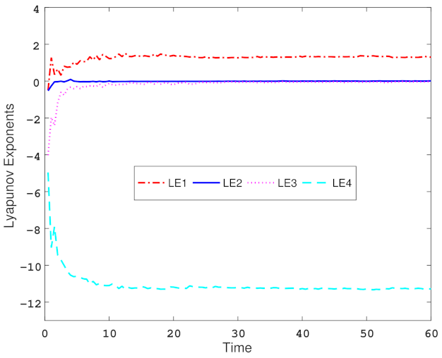
The Lyapunov exponent is used to represent the average exponential convergence or divergence rate between adjacent orbits in phase space, and it can determine the state of motion of a nonlinear system. If the system has a positive Lyapunov exponent, it indicates that the system is chaotic [42,43]. The Lyapunov exponent of the state variable of the hyper-chaotic system is calculated by the Wolf method [42], Figure 4 depicts the Lyapunov exponential spectrum of the Chen hyper-chaotic system. It is intuitive to see that the third and fourth Lyapunov exponents of the system are negative. Combined with the data analysis in Table 1, when the Lyapunov indicators of the four state variables are stable, it can be obtained that L E 1 = 1.3040 , L E 2 = 0.0158 , L E 3 = 0.0314 , and L E 4 = 11.2900 . The Kaplan–Yorke dimension of the Chen hyper-chaotic system [44] is defined as:
D K Y = η + η = 1 η L E η | L E η + 1 | = 3 + 1.3040 + 0.0158 0.0314 | 11.2900 | = 3.114 .
According to the conditions of the hyper-chaotic system, the system satisfies the condition that the Lyapunov exponent of two state variables is greater than zero and the sum of the exponents is negative, and the Lyapunov dimension is fractional, so it can be judged as a hyper-chaotic system.
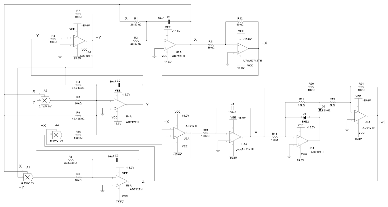
In order to verify the correctness of the numerical simulation, the modular circuit of the Chen hyper-chaotic system based on the memristor will be built, as shown in Figure 5. The absolute value circuit module of the memristor is composed of a capacitor, two diodes, four operational amplifiers, and six resistors.
Remark 1.
In the circuit, the power supply voltage is usually ± 15 v , and the power supply voltage range of operational amplifiers, multipliers, and other devices is about ± 13.5 v . The variables of the attractor phase diagram in Figure 3 exceed this range, so it is necessary to perform a proper linear transformation without changing the performance of the system; each variable is uniformly compressed by a factor of 10.
Based on the above, analytical calculations of the part of the circuit that has a capacitor are performed, and by using KCL and KVL [45], the circuit simulation diagram calculates the corresponding circuit equation as follows
d x d t = 1 C 1 R 2 y 1 C 1 R 1 x , d y d t = 1 C 2 R 4 y 1 C 2 R 3 x z 1 C 2 R 9 x + 1 C 2 R 16 x | w | , d z d t = 1 C 3 R 6 x y 1 C 3 R 5 z , d w d t = 1 C 4 R 10 x .
By comparing the coefficients of each variable in system (7), we can calculate the corresponding values, which are indicated in the circuit simulation diagram and are not given here. The phase diagram of the attractor observed on the oscilloscope is shown in Figure 6, which is consistent with the attractor simulated in Figure 3 through comparison.

3. Model Description and Some Initial Conditions

The following is a class of nonlinear systems with external inputs:
y ˙ ( t ) = M y ( t ) + N f ( y ( t ) ) + U ( t ) , y t 0 = y 0 ,
where M is a constant matrix, N is an orthogonal matrix, y R n presents a state vector, and f · = ( f 1 · , f 2 · , · · · , f n · ) T R n is a continuous nonlinear function that satisfies f ( 0 ) = 0 . Letting t 0 = 0 , y 0 R n be a given vector. Suppose that L 0 is a diagonal matrix that satisfies | | f ( ξ ( t ) ) | | 2 ξ T ( t ) L ξ ( t ) for any ξ R n , U ( t ) is an external input to system (10) and also an effective control gain, defined as follows
U ( t ) = K 1 y ( t ) , t ( μ T , μ T + T 3 ) , 0 , t ( μ T + T 3 , μ T + 2 T 3 ) , K 2 y ( t ) , t ( μ T + 2 T 3 , ( μ + 1 ) T ) .
Considering the segment control mechanism of (11), system (10) can be written as
y ˙ ( t ) = M y ( t ) + N f ( y ( t ) ) + K 1 y ( t ) , t ( μ T , μ T + T 3 ) , y ˙ ( t ) = M y ( t ) + N f ( y ( t ) ) , t ( μ T + T 3 , μ T + 2 T 3 ) , y ˙ ( t ) = M y ( t ) + N f ( y ( t ) ) + K 2 y ( t ) , t ( μ T + 2 T 3 , ( μ + 1 ) T ) , y ( t ) = ( I + J i ) y ( t ) , t = μ T + i 3 T , y ( t 0 ) = y 0 ,
where μ is an integer, ( μ 0 ), and K i ( i = 1 , 2 ) and J i ( i = 1 , 2 , 3 ) R n × n are constant matrices. T, which is an integer greater than 0, denotes a period of the system. The solution of system (10) satisfies the right continuous condition at the jump point t = t ϖ and the jump in the state variable y is represented by Δ y ( t ϖ ) = y ( t ϖ + ) y ( t ϖ ) , y ( t ϖ ) = y ( t ϖ + ) , y ( t ϖ ) = lim t t ϖ y ( t ) and y ( t ϖ + ) = lim t t ϖ + y ( t ) .
Remark 2.
Without losing generality, suppose that J 2 and J 3 are null matrices, then there will be no external impulses in the second half of the system, and the system proposed in this article will be a special sandwich control system, which means that the system model proposed in this paper extends the model in [46].
In order to describe our main results more clearly, the following lemmas are useful.
Lemma 1
([47]). Let Z i ( i = 1 , 2 , 3 ) R n × m , Z 3 = Z 3 T > 0 , and suppose there exists a scalar constant ϖ that satisfies ϖ 0 , then the following inequality is satisfied:
Z 1 T Z 2 + Z 2 T Z 1 ϖ Z 1 T Z 3 Z 1 + ϖ 1 Z 2 T Z 3 1 Z 2 .
Lemma 2
([48]).
Suppose that A ( ξ ) = A T ( ξ ) , D ( ξ ) = D T ( ξ ) , and
A ( ξ ) B ( ξ ) B T ( ξ ) D ( ξ ) > 0 ,
Then the above linear matrix inequality can be rewritten as the following inequality
D ( ξ ) > 0 , A ( ξ ) B ( ξ ) D 1 ( ξ ) B T ( ξ ) > 0 .

4. Theoretical Analysis and Main Results

Theorem 1.
Let ν j > 0 and ψ j > 0 ( j = 1 , 2 , 3 ) where ν j and ψ j are positive scalar constants and denote P as a symmetric and positive definite matrix. Suppose the following inequality conditions hold
P M + M T P + P K 1 + K 1 T P + ψ 1 1 L ν 1 P P N P N ψ 1 1 I 0 ,
P M + M T P + ψ 2 1 L ν 2 P P N P N ψ 2 1 I 0 ,
P M + M T P + P K 2 + K 2 T P + ψ 3 1 L ν 3 P P N P N ψ 3 1 I 0 ,
ν 1 + ν 2 + ν 3 T 3 + ln λ 1 + ln λ 2 + ln λ 3 < 0 ,
where λ j = λ D ( P 1 ( I + J j ) T P ( I + J j ) ) ( j = 1 , 2 , 3 ) , then it can be deduced that system (12) satisfies the condition of being exponentially stable at the origin.
Proof of Theorem 1.
Consider constructing a class of Lyapunov function,
V ( y ( t ) ) = y T ( t ) P y ( t ) ,
from (17), an inequality can be obtained as follows:
λ X ( P ) | | y ( t ) | | 2 V ( y ( t ) ) λ D ( P ) | | y ( t ) | | 2 .
Suppose that t ( μ T , μ T + T 3 ) , by means of the above, then
V ˙ ( y ( t ) ) = 2 y T ( t ) P y ˙ ( t ) = 2 y T ( t ) P ( M y ( t ) + K 1 y ( t ) ) + y T ( t ) P N f ( y ( t ) ) + f T ( y ( t ) ) N T P y ( t ) y T ( t ) [ P M + M T P + P K 1 + K 1 T P ] y ( t ) + ψ 1 y T ( t ) P N N T P y ( t ) + ψ 1 1 y T ( t ) L y ( t ) = ν 1 V ( y ( t ) ) + y T ( t ) [ P M + M T P + P K 1 + K 1 T P + ψ 1 P N N T P + ψ 1 1 L ν 1 P ] y ( t ) ν 1 V ( y ( t ) ) ,
and it can be obtained that
V ( y ( t ) ) V ( y ( ( μ T ) + ) ) e x p ( ν 1 ( t μ T ) ) .
Suppose that t = μ T + T 3 , then
V ( y ( t ) ) | t = μ T + T 3 = [ ( I + J 1 ) y ( t ) ] T P [ ( I + J 1 ) y ( t ) ] λ 1 V ( y ( t ) ) .
Suppose that t ( μ T + T 3 , μ T + 2 T 3 ) , it is then possible to obtain
V ˙ ( y ( t ) ) = 2 y T ( t ) P y ( t ) ˙ y T ( t ) [ P M + M T P ] y ( t ) + ψ 2 y T ( t ) P N N T P y ( t ) + ψ 2 1 y T ( t ) L y ( t ) = ν 2 V ( y ( t ) ) + y T ( t ) [ P M + M T P + ψ 2 P N N T P + ψ 2 1 L ν 2 P ] y ( t ) ν 2 V ( y ( t ) ) ,
from the above, it can be obtained that
V ( y ( t ) ) V ( y ( μ T + T 3 ) + ) e x p ( ν 2 ( t μ T T 3 ) ) λ 1 V ( y ( μ T + T 3 ) ) e x p ( ν 2 ( t μ T T 3 ) ) .
Suppose that t = μ T + 2 T 3 , then
V ( y ( t ) ) | t = μ T + 2 T 3 λ 2 V ( y ( t ) ) .
Suppose that t ( μ T + 2 T 3 , ( μ + 1 ) T ) , similar to the previous derivation process, the results are directly given here; it can be obtained that
V ˙ ( y ( t ) ) ν 3 V ( y ( t ) ) ,
then
V ( y ( t ) ) V ( y ( μ T + 2 T 3 ) + ) e x p ( ν 3 ( t μ T 2 T 3 ) ) λ 2 V ( y ( μ T + 2 T 3 ) ) e x p ( ν 3 ( t μ T 2 T 3 ) ) .
Suppose that t = ( μ + 1 ) T ; it is then possible to obtain
V ( y ( t ) ) | t = ( μ + 1 ) T λ 3 V ( y ( t ) ) .
From (19)–(27), combined with mathematical induction, several inferences can be obtained as follows:
Case 1 When the value of μ takes 0, there are different scenarios as follows.
Subcase 1 Suppose that t ( 0 , T 3 ) ; it can be obtained that
V ( y ( t ) ) V ( y 0 ) e x p ( ν 1 t ) ,
therefore,
V ( y ( T 3 ) ) V ( y 0 ) e x p ( ν 1 T 3 ) .
Subcase 2 Suppose that t [ T 3 , 2 T 3 ) , then
V ( y ( t ) ) λ 1 V ( y ( ( T 3 ) ) ) e x p ( ν 2 ( t T 3 ) ) λ 1 V ( y 0 ) e x p ( ν 1 T 3 + ν 2 ( t T 3 ) ) ,
therefore,
V ( y ( 2 T 3 ) ) λ 1 V ( y 0 ) e x p ( ν 1 T 3 + ν 2 T 3 ) .
Subcase 3 Suppose that t [ 2 T 3 , T ) , then
V ( y ( t ) ) λ 2 V ( y ( 2 T 3 ) ) e x p ( ν 3 ( t 2 T 3 ) ) λ 1 λ 2 V ( y 0 ) e x p ( ν 1 T 3 + ν 2 T 3 + ν 3 ( t 2 T 3 ) ) ,
therefore,
V ( y ( T ) ) λ 1 λ 2 V ( y 0 ) e x p ( ν 1 T 3 + ν 2 T 3 + ν 3 T 3 ) .
Subcase 4 If t = T , then
V ( y ( t ) ) | t = T λ 3 V ( ( y ( T ) ) ) λ 1 λ 2 λ 3 V ( y 0 ) e x p ( ν 1 T 3 + ν 2 T 3 + ν 3 T 3 ) .
Case 2 When the value of μ takes the value 1, then
Subcase 1 Suppose that t ( T , T + T 3 ) , it can be obtained that
V ( y ( t ) ) V ( y ( T ) + ) e x p ( ν 1 ( t T ) ) λ 1 λ 2 λ 3 V ( y 0 ) e x p ( ν 1 ( t 2 T 3 ) + ν 2 T 3 + ν 3 T 3 ) ,
therefore,
V ( y ( T + T 3 ) ) λ 1 λ 2 λ 3 V ( y 0 ) e x p ( ν 1 2 T 3 + ν 2 T 3 + ν 3 T 3 ) .
Subcase 2 Suppose that t [ T + T 3 , T + 2 T 3 ) , then
V ( y ( t ) ) λ 1 V ( y ( T + T 3 ) ) e x p ( ν 2 ( t T T 3 ) ) λ 1 2 λ 2 λ 3 V ( y 0 ) e x p ( ν 1 2 T 3 + ν 2 ( t T ) + ν 3 T 3 ) ,
therefore,
V ( y ( T + 2 T 3 ) ) λ 1 2 λ 2 λ 3 V ( y 0 ) e x p ( ν 1 2 T 3 + ν 2 2 T 3 + ν 3 T 3 ) .
Subcase 3 Suppose that t [ T + 2 T 3 , 2 T ) , then
V ( y ( t ) ) λ 2 V ( y ( T + 2 T 3 ) ) e x p ( ν 3 ( t T 2 T 3 ) ) λ 1 2 λ 2 2 λ 3 V ( y 0 ) e x p ( ν 1 2 T 3 + ν 2 2 T 3 + ν 3 ( t 4 T 3 ) ) ,
therefore,
V ( y ( 2 T ) ) λ 1 2 λ 2 2 λ 3 V ( y 0 ) e x p ( ν 1 2 T 3 + ν 2 2 T 3 + ν 3 2 T 3 ) .
Subcase 4 Suppose that t = 2 T , it can be obtained that
V ( y ( t ) ) | t = 2 T λ 3 V ( y ( 2 T ) ) λ 1 2 λ 2 2 λ 3 2 V ( y 0 ) e x p ( ν 1 2 T 3 + ν 2 2 T 3 + ν 3 2 T 3 ) .
From the previous derivation process of Theorem 1, combined with mathematical induction, the following relationship is obtained:
Case k + 1 When the value of μ takes the value k, mathematical induction is used as in the following scenarios
Subcase 1 Suppose that t ( k T , k T + T 3 ) , then
V ( y ( t ) ) λ 1 k λ 2 k λ 3 k V ( y 0 ) e x p ( ν 1 ( t 2 k T 3 ) + ν 2 k T 3 + ν 3 k T 3 ) .
Subcase 2 Suppose that t [ k T + T 3 , k T + 2 T 3 ) , then
V ( y ( t ) ) λ 1 k + 1 λ 2 k λ 3 k V ( y 0 ) e x p ( ν 1 ( k + 1 ) T 3 + ν 2 ( t ( 2 k + 1 ) T 3 ) + ν 3 k T 3 ) .
Subcase 3 Suppose that t [ k T + 2 T 3 , ( k + 1 ) T ) , it can be obtained that
V ( y ( t ) ) λ 1 k + 1 λ 2 k + 1 λ 3 k V ( y 0 ) e x p ( ν 1 ( k + 1 ) T 3 + ν 2 ( k + 1 ) T 3 + ν 3 ( t ( 2 k + 2 ) T 3 ) ) .
Subcase 4 If t = ( k + 1 ) T , then
V ( y ( t ) ) | t = ( k + 1 ) T λ 1 k + 1 λ 2 k + 1 λ 3 k + 1 V ( y 0 ) e x p ( ν 1 ( k + 1 ) T 3 + ν 2 ( k + 1 ) T 3 + ν 3 ( k + 1 ) T 3 ) .
From inequality (28) and letting t = k T , the following relationship is obtained:
V ( y ( t ) ) λ 1 k λ 2 k λ 3 k V ( y 0 ) e x p ( ν 1 k T 3 + ν 2 k T 3 + ν 3 k T 3 ) V ( y 0 ) e x p ( k [ ( ν 1 + ν 2 + ν 3 ) T 3 + ( l n λ 1 + l n λ 2 + l n λ 3 ) ] ) ,
where k T < t < k T + T 3 .
From inequality (29) and letting t = k T + 2 T 3 , the following relationship is obtained:
V ( y ( t ) ) λ 1 k + 1 λ 2 k λ 3 k V ( y 0 ) e x p ( ν 1 ( k + 1 ) T 3 + ν 2 ( k + 1 ) T 3 + ν 3 k T 3 ) V ( y 0 ) e x p ( k [ ( ν 1 + ν 2 + ν 3 ) T 3 + ( l n λ 1 + l n λ 2 + l n λ 3 ) ] + l n λ 1 + ν 1 T 3 + ν 2 T 3 ) ,
where k T + T 3 t < k T + 2 T 3 .
From inequality (30) and letting t = ( k + 1 ) T , there is the following inequality:
V ( y ( t ) ) λ 1 k + 1 λ 2 k + 1 λ 3 k V ( y 0 ) e x p ( ν 1 ( k + 1 ) T 3 + ν 2 ( k + 1 ) T 3 + ν 3 ( k + 1 ) T 3 ) V ( y 0 ) e x p ( k [ ( ν 1 + ν 2 + ν 3 ) T 3 + ( l n λ 1 + l n λ 2 + l n λ 3 ) ] + ln λ 1 + ln λ 2 + ν 1 T 3 + ν 2 T 3 + ν 3 T 3 ) ,
where k T + 2 T 3 t < ( k + 1 ) T .
From inequality (31), and supposing that t = ( k + 1 ) T , it can be obtained that
V ( y ( t ) ) | t = ( k + 1 ) T λ 1 k + 1 λ 2 k + 1 λ 3 k + 1 V ( y 0 ) e x p ( ν 1 ( k + 1 ) T 3 + ν 2 ( k + 1 ) T 3 + ν 3 ( k + 1 ) T 3 ) V ( y 0 ) e x p ( ( k + 1 ) [ ( ν 1 + ν 2 + ν 3 ) T 3 + ( l n λ 1 + l n λ 2 + l n λ 3 ) ] ) .
Remark 3.
Combining Theorem 1 and the corollary from above with the relevant conditions, it can be deduced that as t tends to infinity, k also tends to infinity, in which case lim t V ( y ( t ) ) = 0 . It follows the theoretical proof that system (12) is exponentially stable at the origin is completed. At this point, the validity and feasibility of Theorem 1 in this paper is confirmed.

5. Numerical Simulation Example

To further strengthen the persuasiveness of this paper, a numerical case simulation will be used to confirm the validity and feasibility of this paper.
Example 1.
From the analysis in Section 2 of this paper, it is clear that system (7) can be described as
y ˙ = M y + N f ( y ) ,
where
M = 35 35 0 0 22 28 0 0 0 0 3 0 1 0 0 0 , N = 1 0 0 0 0 1 0 0 0 0 1 0 0 0 0 1 ,
and
f ( y ) = 0 y 1 y 3 + 0.02 y 1 | y 4 | y 1 y 2 0 .
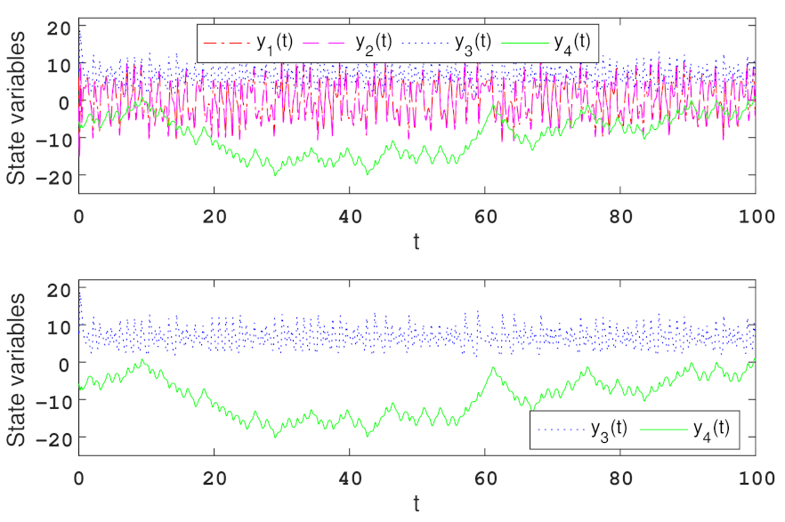
Suppose that y 1 ζ , ζ , where ζ > 0 is a constant, meanwhile, letting | y 4 | | y 3 | . It can be obtained that
| | f ( y ) | | 2 = y 1 2 y 3 2 + ( 0.02 ) 2 y 1 2 y 4 2 + y 1 2 y 2 2 0.04 y 1 2 y 3 | y 4 | 0.96 y 1 2 y 3 2 + 0.0004 y 1 2 y 4 2 + y 1 2 y 2 2 .
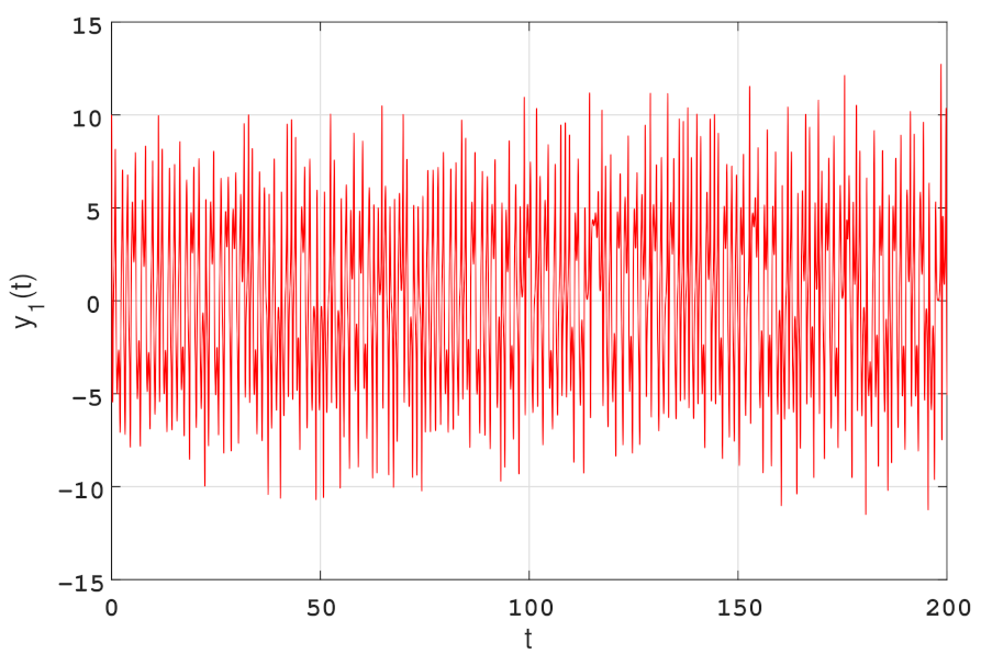
If y ( 0 ) = [ 6 , 2 , 8 , 6 ] T , as shown in Figure 7, it can be obtained that | y 1 | 15 , then
L = d i a g ( 0 , ζ 2 , 0.96 ζ 2 , 0.0004 ζ 2 ) = d i a g ( 0 , 225 , 216 , 0.09 ) .
Choosing a time width of 100, it can be seen from Figure 8 that | y 4 | | y 3 | is always satisfied; Figure 8 illustrates the chaotic time series with the initial condition y ( 0 ) = [ 6 , 2 , 8 , 6 ] T .
Choosing
K 1 = d i a g ( 4 , 5 , 6 , 5 ) ,
K 2 = d i a g ( 8 , 6 , 8 , 6 ) .
Suppose that T = 0.012, then calculate the three LMIs in Theorem 1 and inequality ν 1 + ν 2 + ν 3 T 3 + ln λ 1 + ln λ 2 + ln λ 3 < 0 , the following set of feasible solutions can be obtained:
ν 1 = 65 , ν 2 = 66 , ν 3 = 67 , ψ 1 = 35 , ψ 2 = 30 , ψ 3 = 37 ,
P = 0.7896 0.4657 0 0.0005 0.4657 0.7171 0 0.0069 0 0 0.9652 0 0.0005 0.0069 0 0.9191 , J 1 = 0.88 0.02 0 0 0 0.98 0.22 0 0.02 0 1.08 0 0 0 0.02 0.94 ,
J 2 = 1.08 0.22 0 0 0 0.96 0.16 0 0.01 0 1.04 0 0 0 0.02 0.98 , J 3 = 0.96 0.06 0 0 0 1.05 0.12 0 0.04 0 1.02 0 0 0 0.04 1.08 .
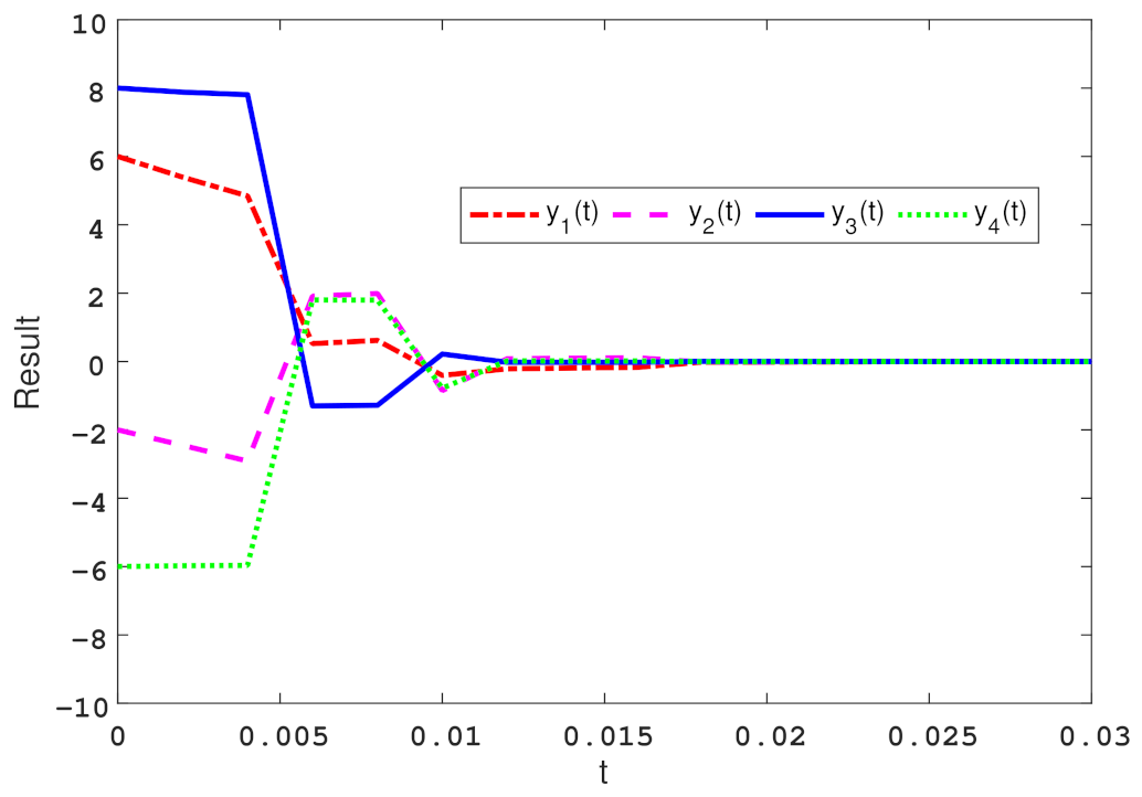
Based on the results obtained above, the feasibility of Theorem 1 of this paper is confirmed. As shown in the simulation results below, this system will stabilize in two periods as t increases. Therefore, it can be deduced that system (12) is exponentially stable at the origin by Theorem 1. Figure 9 depicts the state response curves of the controlled system with three-stage-impulse, where the initial conditions are set to y ( 0 ) = [ 6 , 2 , 8 , 6 ] T .

6. Conclusions

In this paper, a new hyper-chaotic system is designed based on the three-dimensional Chen system, using a smooth continuous nonlinear flux-controlled memristor model as the nonlinear feedback of this system, allowing the newly designed system to contain rich dynamical behavior. Some stability criteria are obtained based on the linear matrix inequality. Meanwhile, by using numerical simulation, the memristor-based Chen hyper-chaotic system can be stabilized by the method proposed in this paper; this method can also be extended to other nonlinear systems. Hyper-chaotic systems with unpredictability and complex dynamics can be extended to the field of secure communication, which will adopt synchronization control to achieve secure communication in the future.

Author Contributions

Conceptualization, Y.F.; Formal analysis, X.X.; Funding acquisition; S.W. and Y.F.; Supervision, S.W.; Writing, X.X. and B.O.O. All authors have read and agreed to the published version of the manuscript.

Funding

This work is supported by the Science and Technology Research Program of Chongqing Municipal Education Commission (No. KJZD-M202201204).

Data Availability Statement

There is no data associated with this paper.

Conflicts of Interest

The authors declare that they have no conflict of interest.

References

  1. Lorenz, E.N. Deterministic nonperiodic flow. J. Atmos. Sci. 1963, 20, 130–141. [Google Scholar] [CrossRef]
  2. Ueta, T.; Chen, G. Bifurcation analysis of Chen’s equation. Int. J. Bifurc. Chaos 2000, 10, 1917–1931. [Google Scholar] [CrossRef]
  3. Wu, C.; Zhang, Y.; Yang, N. Analysis of a novel four-wing hyperchaotic system from pseudo to real and circuit experimental research. In Proceedings of the 2014 International Conference on Information Science, Electronics and Electrical Engineering (ISEEE), Harbin, China, 17–18 May 2014; pp. 1138–1142. [Google Scholar] [CrossRef]
  4. Bao, B.; Liu, Z.; Xu, J. New chaotic system and its hyperchaos generation. J. Syst. Eng. Electron. 2009, 20, 1179–1187. [Google Scholar]
  5. Zhang, S.; Zeng, Y.; Li, Z. A novel four-dimensional no-equilibrium hyper-chaotic system with grid multiwing hyper-chaotic hidden attractors. J. Comput. Nonlinear Dyn. 2018, 13, 090908. [Google Scholar] [CrossRef]
  6. Laarem, G. A new 4-D hyper chaotic system generated from the 3-D Rösslor chaotic system, dynamical analysis, chaos stabilization via an optimized linear feedback control, it’s fractional order model and chaos synchronization using optimized fractional order sliding mode control. Chaos Soliton Fractals 2021, 152, 111437. [Google Scholar] [CrossRef]
  7. Chua, L.O. Memristor-the missing circuit element. IEEE Trans. Circuit Theory 1971, 18, 507–519. [Google Scholar] [CrossRef]
  8. Strukov, D.B.; Snider, G.S.; Stewart, D.R.; Williams, R.S. The missing memristor found. Nature 2008, 453, 80–83. [Google Scholar] [CrossRef]
  9. Sahin, M.; Taskiran, Z.C.; Guler, H.; Hamamci, S. Simulation and implementation of memristive chaotic system and its application for communication systems. Sens. Actuators A-Phys. 2019, 290, 107–118. [Google Scholar] [CrossRef]
  10. Itoh, M.; Chua, L.O. Memristor oscillators. Int. J. Bifurc. Chaos 2008, 18, 3183–3206. [Google Scholar] [CrossRef]
  11. Bao, B.; Bao, H.; Wang, N.; Xu, Q. Hidden extreme multistability in memristive hyperchaotic system. Chaos Soliton Fractals 2017, 94, 102–111. [Google Scholar] [CrossRef]
  12. Xi, H.; Li, Y.; H, X. Generation and nonlinear dynamical analyses of fractional-order memristor-based Lorenz systems. Entropy 2014, 16, 6240–6253. [Google Scholar] [CrossRef] [Green Version]
  13. Wang, X.; Min, X.; Zhou, P.; Yu, D. Hyperchaotic circuit based on memristor feedback with multistability and symmetries. Complexity 2020, 2020, 2620375. [Google Scholar] [CrossRef] [Green Version]
  14. Wang, M.; Deng, Y.; Liao, X.; Li, Z.; Ma, M.; Zeng, Y. Dynamics and circuit implementation of a four-wing memristive chaotic system with attractor rotation. Int. J. Nonlinear Mech. 2019, 111, 149–159. [Google Scholar] [CrossRef]
  15. Tu, Z.; Wang, D.; Yang, X.; Cao, J. Lagrange stability of memristive quaternion-valued neural networks with neutral items. Neurocomputing 2020, 339, 380–389. [Google Scholar] [CrossRef]
  16. Chen, M.; Sun, M.; Bao, B.; Wu, H.; Xu, Q.; Wang, J. Controlling extreme multistability of memristor emulator-based dynamical circuit in flux–charge domain. Nonlinear Dyn. 2018, 91, 1395–1412. [Google Scholar] [CrossRef]
  17. Li, H.; Yang, Y.; Li, W.; He, S.; Li, C. Extremely rich dynamics in a memristor-based chaotic system. Eur. Phys. J. Plus 2020, 135, 579. [Google Scholar] [CrossRef]
  18. Lai, Q.; Wan, Z.; Kuate, P.D.; Fotsin, H. Coexisting attractors, circuit implementation and synchronization control of a new chaotic system evolved from the simplest memristor chaotic circuit. Commun. Nonlinear Sci. 2020, 89, 105341. [Google Scholar] [CrossRef]
  19. Huang, L.; Wang, Y.; Jiang, Y.; Lei, T. A Novel Memristor Chaotic System with a Hidden Attractor and Multistability and Its Implementation in a Circuit. Math. Probl. Eng. 2021, 2021, 7457220. [Google Scholar] [CrossRef]
  20. Akif, A.; Karthikeyan, R.; Ali, D.; Muhammed, A.P.; Mustafa, Z.Y. A simple fractional-order chaotic system based on memristor and memcapacitor and its synchronization application. Chaos Soliton Fractals 2021, 152, 111306. [Google Scholar] [CrossRef]
  21. Wang, Z.; Qi, G. Modeling and analysis of a three-terminal-memristor-based conservative chaotic system. Entropy 2021, 23, 71. [Google Scholar] [CrossRef]
  22. Wang, X.; Gao, M.; Lu, H.C.; Wang, C. Tri-valued memristor-based hyper-chaotic system with hidden and coexistent attractors. Chaos Soliton Fractals 2022, 159, 112177. [Google Scholar] [CrossRef]
  23. Khan, A.; Tyagi, B. Analysis and hyper-chaos control of a new 4-D hyper-chaotic system by using optimal and adaptive control design. Int. J. Dyn. Control 2017, 5, 1147–1155. [Google Scholar] [CrossRef]
  24. Vaidyanathan, S.; Abba, O.A.; Gambo, B.; Alidou, M. A new three-dimensional chaotic system: Its adaptive control and circuit design. Int. J. Autom. Control 2019, 13, 101–121. [Google Scholar] [CrossRef]
  25. Li, D.; Lu, S.; Liu, L. Adaptive NN cross backstepping control for nonlinear systems with partial time-varying state constraints and its applications to hyper-chaotic systems. IEEE. Trans. Syst. Man. Cybern. Syst. 2021, 51, 2821–2832. [Google Scholar] [CrossRef]
  26. Tu, Z.; Ding, N.; Li, L.; Feng, Y.; Zou, L.; Zhang, W. Adaptive synchronization of memristive neural networks with time-varying delays and reaction-diffusion term. Appl. Math. Comput. 2017, 311, 118–128. [Google Scholar] [CrossRef]
  27. Hosseinabadi, P.A.; Abadi, A.S.S.; Mekhilef, S. Adaptive terminal sliding mode control of hyper-chaotic uncertain 4-order system with one control input. In Proceedings of the 2018 IEEE Conference on Systems, Process and Control (ICSPC), Melaka, Malaysia, 31 August–14 December 2018; pp. 94–99. [Google Scholar] [CrossRef]
  28. Mofid, O.; Momeni, M.; Mobayen, S.; Fekih, A. A Disturbance-Observer-Based Sliding Mode Control for the Robust Synchronization of Uncertain Delayed Chaotic Systems: Application to Data Security. IEEE Access 2021, 9, 16546–16555. [Google Scholar] [CrossRef]
  29. Lee, S.; Park, M.; Kwon, O.; Selvaraj, P. Improved Synchronization Criteria for Chaotic Neural Networks with Sampled-data Control Subject to Actuator Saturation. Int. J. Control Autom. 2019, 17, 2430–2440. [Google Scholar] [CrossRef]
  30. Wu, H.; Li, C.; He, Z.; Wang, Y.; He, Y. Lag synchronization of nonlinear dynamical systems via asymmetric saturated impulsive control. Chaos Soliton Fractals 2021, 152, 111290. [Google Scholar] [CrossRef]
  31. Sabaghian, A.; Balochian, S. Parameter estimation and synchronization of hyper chaotic Lu system with disturbance input and uncertainty using two under-actuated control signals. Trans. Inst. Meas. Control 2019, 41, 1729–1739. [Google Scholar] [CrossRef]
  32. Sabaghian, A.; Balochian, S.; Yaghoobi, M. Synchronisation of 6D hyper-chaotic system with unknown parameters in the presence of disturbance and parametric uncertainty with unknown bounds. Connect. Sci. 2020, 32, 362–383. [Google Scholar] [CrossRef]
  33. Yang, X.; Liu, Y.; Cao, J.; Leszek, R. Synchronization of coupled time-delay neural networks with mode-dependent average dwell time switching. IEEE Trans. Neural Netw. Learn. Syst. 2020, 31, 5483–5496. [Google Scholar] [CrossRef]
  34. Yang, X.; Wan, X.; Cheng, Z.; Cao, J.; Liu, Y.; Leszek, R. Synchronization of switched discrete-time neural networks via quantized output control with actuator fault. IEEE Trans. Neural Netw. Learn. Syst. 2020, 32, 4191–4201. [Google Scholar] [CrossRef] [PubMed]
  35. Li, Z.; Ke, T.; Xia, Q.; Xie, C.; Xu, Y. Finite-Time Impulsive Control of Financial Risk Dynamic System with Chaotic Characteristics. Connect. Sci. 2021, 2021, 5207154. [Google Scholar] [CrossRef]
  36. Li, X.; Li, P. Stability of time-delay systems with impulsive control involving stabilizing delays. Automatica 2021, 124, 109336. [Google Scholar] [CrossRef]
  37. Li, C.; Wu, S.; Feng, G.; Liao, X. Stabilizing effects of impulses in discrete-time delayed neural networks. IEEE Trans. Neural Netw. 2011, 22, 323–329. [Google Scholar] [CrossRef] [PubMed]
  38. Liao, C.; Tu, D.; Feng, Y.; Zhang, W.; Wang, Z.; Onasanya, B.O. A Sandwich Control System with Dual Stochastic Impulses. IEEE/CAA J. Autom. Sin. 2022, 9, 741–744. [Google Scholar] [CrossRef]
  39. Li, C.; Feng, G.; Huang, T. On hybrid impulsive and switching neural networks. IEEE Trans. Syst. Man Cybern. 2008, 38, 1549–1560. [Google Scholar] [CrossRef]
  40. Bao, B.; Xu, J.; Liu, Z. Initial state dependent dynamical behaviors in a memristor based chaotic circuit. Chaos Soliton Fractals 2010, 27, 070504. [Google Scholar] [CrossRef]
  41. Wang, W.; Zeng, Y.; Sun, R. Research on a six-order chaotic circuit with three memristors. Acta Phys. Sin. 2017, 66. [Google Scholar] [CrossRef]
  42. Wolf, A.; Swift, J.B.; Swinney, H.L.; Vastano, J.A. Determining Lyapunov exponents from a time series. Physica D 1985, 16, 285–317. [Google Scholar] [CrossRef] [Green Version]
  43. Leutcho, G.; Kengne, J.; Kengne, L.K. Dynamical analysis of a novel autonomous 4-D hyperjerk circuit with hyperbolic sine nonlinearity: Chaos, antimonotonicity and a plethora of coexisting attractors. Chaos Soliton Fractals 2018, 107, 67–87. [Google Scholar] [CrossRef]
  44. Frederickson, P.; Kaplan, J.L.; Yorke, E.D.; Yorke, J.A. The Liapunov dimension of strange attractors. J. Differ. Equ. 1983, 49, 185–207. [Google Scholar] [CrossRef] [Green Version]
  45. Gabelli, J.; Fve, G.; Berroir, B.; Etienne, B.; Glattli, D. Violation of Kirchhoff’s Laws for a Coherent RC Circuit. Science 2006, 313, 499–502. [Google Scholar] [CrossRef] [PubMed] [Green Version]
  46. Feng, Y.; Li, C.; Huang, T. Sandwich control systems. In Proceedings of the 2015 Sixth International Conference on Intelligent Control and Information Processing (ICICIP), Wuhan, China, 26–28 November 2015; pp. 1–5. [Google Scholar] [CrossRef]
  47. Sanchez, E.N.; Perez, J.P. Input-to-state stability (ISS) analysis for dynamic neural networks. Chaos Soliton Fractals 1999, 46, 1395–1398. [Google Scholar] [CrossRef]
  48. Boyd, S.; Ghaoui, L.E.; Feron, E. Linear Matrix Inequalities in System and Control Theory. Chaos Soliton Fractals 1994, 15, 157–193. [Google Scholar] [CrossRef]
Figure 1. The fundamental concept of the three-stage-impulse control systems.
Mathematics 10 04560 g001
Figure 2. Improved circuit diagram of the Chen system.
Mathematics 10 04560 g002
Figure 3. Phase portraits of the hyper-chaotic Chen system attractor. (a) xy plane. (b) x z plane. (c) y w plane.
Mathematics 10 04560 g003
Figure 4. The Lyapunov exponential spectrum of the hyper-chaotic Chen system.
Mathematics 10 04560 g004
Figure 5. Circuit diagram of Chen hyper-chaotic system with a memristor feedback.
Mathematics 10 04560 g005
Figure 6. Phase portraits of Chen hyper-chaotic system attractor. (a) x y channel. (b) x z channel. (c) y w channel.
Mathematics 10 04560 g006
Figure 7. Time domain range of variable y 1 ( t ) .
Mathematics 10 04560 g007
Figure 8. Time domain waveforms of state variables.
Mathematics 10 04560 g008
Figure 9. State response curves of controlled system with three-stage-impulse.
Mathematics 10 04560 g009
Table 1. Lyapunov exponents.
Time LE 1 LE 2 LE 3 LE 4
t = 0.5 0.4920 0.5292 4.0250 4.9560
t = 1 1.2790 0.2638 1.9660 9.0480
t = 59.5 1.3060 0.0039 0.0354 11.2700
t = 60 1.3040 0.0158 0.0314 11.2900
Publisher’s Note: MDPI stays neutral with regard to jurisdictional claims in published maps and institutional affiliations.