Abstract
CO2 is regarded as an effective and environmentally friendly refrigerant. Using a CO2 ejector is a proven method for enhancing the effectiveness of a transcritical CO2 refrigerant system. However, the complex internal flow of a CO2 ejector, involving supersonic effects, phase change effects, metastable effects, and so on, makes it difficult to understand. In order to summarize the current state of the technology and knowledge gaps, this work provides a comprehensive literature review on CO2 ejectors. In the first part, mathematical modelling and simulation calculations of CO2 ejectors are presented, and an overview and classification of ejector models are given. In the second part, the structural optimization part of the ejector is described in detail, and the nozzle structure, the mixing chamber length, improvements to multi-jet systems, and the impact of these factors on the system performance are analyzed. In the third part, flow visualization is used to study the complex flow phenomenon, and the effect of the shock wave on the entrained rate of the ejector is discussed. Finally, the paper outlines the relationship between all ejector technologies, working fluids, and ejector performance and makes valid recommendations for further research and development of CO2 ejectors.
Keywords:
CO2 ejector; mathematical model; structural optimization; shock wave; visualization experiment MSC:
76-05; 76-10
1. Introduction
Refrigeration technology is inextricably linked to the lives of humans, and as environmental concerns grow more serious, governments and scientific institutions are increasingly emphasizing environmentally friendly refrigerants. Due to its non-toxicity, non-flammability, negligible GWP (global warming potential), and minimal ODP (ozone depression potential), CO2 is a desirable gas for use in refrigeration systems. Much effort is currently being expended to highlight the advantages of the CO2 refrigeration systems [1,2,3].
In conventional vapor compression refrigeration systems (VCRS) that use a CO2 refrigerant, a significant quantity of energy cannot be recovered due to the transcritical operation and is lost during the throttling process. Therefore, there is an urgent need for a throttling component that can recover low pressure. The use of an ejector makes the expansion process nearly isentropic, recovering the kinetic energy of the process [4]. This method is effective at reducing irreversible losses during the throttling process and leads to improvements in the overall system efficiency and the compressor suction pressure. A CO2 ejector is composed of four elements: a motive nozzle, a suction chamber, a mixing chamber, and a diffuser. A transcritical CO2 expansion ejector refrigeration system (EERS) is promising due to the simple design of the ejector, the absence of moving components, and its ease of maintenance. A thorough investigation of CO2 ejectors used in heat pumps and refrigeration systems has been conducted [5]. The effectiveness of an EERS was examined by Deng et al. [6], and it was suggested that an EERS has an 18.6% greater cooling efficiency and a 22.0% higher COP (coefficient of performance) than a VCRS. With regard to CO2 ejector heat pump systems, Zhu et al. [7] performed various experimental tests. This system was more efficient at generating high-temperature hot water than traditional systems, and its COP was 10.3% higher than that of the traditional systems. Santini et al. [8] focused on the influence of high exterior temperatures on EERSs’ performance. Compared with a VCRS, the COP of an EERS increased from 1.83 to 2.64, and the exergy efficiency increased from 29.4% to 34.8%. The presence or absence of ejectors has an impact on the yearly average COP, with a circulating system with ejectors having a 5.5% higher COP than a circulating system without ejectors. According to the thermo-economic analysis suggested by Perez et al. [9], overall investment expenditure and yearly energy consumption expenses might be lowered by 14%. To summarize, CO2 ejector transcritical CO2 refrigeration provides a low carbon cycle with minimal impact on the environment, which increases system performance effectively.
Many studies have been conducted using simulation and experimental tests to improve the CO2 ejector efficiency and its effectiveness on the system characteristics. The original aims of ejector simulations were mainly to provide performance components such as the entrainment ratio and the pressure lift ratio. Most models have been developed to predict these indexes based on the thermodynamic method [10,11,12,13], aerodynamic function method [14,15], and CFD (computational fluid dynamics) method [16,17]. Subsequently, with the deepening of research, the internal flow characteristic was raised as a concern due to the two-phase flow. More and more effort is being put into studying the flow field information inside the ejector, and the single-phase flow model has developed gradually into the two-phase flow model, which considers the metastable flow and nucleation effect. Compared to single-phase flow, complex interactions are introduced via two-phase flow at the boundary between the gas and liquid phases. Furthermore, CFD simulations provide more useful information about the CO2 ejector flow field.
Moreover, to review the current status of the optimization on transcritical CO2 ejector systems, some optimal methods and techniques are utilized, such as changing the motive nozzle geometry, adjusting the mixing chamber structure, designing the multi-ejector combinations, and so on. In addition, most of the current research on shock waves in ejectors is reported, which is based on a combination of theoretical analysis and experimental verification. Experimental studies on shock wave phenomena and properties in ejectors could provide further insights into their effects on ejector performance.
In this paper, we summarize the diversified development of a theoretical model of CO2 ejectors, including the homogeneous equilibrium model (HEM), homogeneous relaxation model (HRM), mixture model, and delayed equilibrium model (DEM), as well as the shock wave. Based on the simulations, the mainstream optimizations of the ejector structure and the ejector refrigeration system are represented. Additionally, investigations into visualization experiments are being conducted, with a focus on the phase change position of the primary flow and the features of the shock waves created at the nozzle exit.
2. Model and Simulation
A CO2 ejector is schematically depicted in Figure 1. The primary flow is at a greater pressure and is accelerated to sound speed at the nozzle throat when it reaches the CO2 ejector. After that, most of the potential energy is converted into kinetic energy, the primary flow pressure is reduced, and the low-pressure CO2 stream enters the ejector as the second flow. The diffuser converts the kinetic energy of mixed fluids into potential energy after the two fluids have been properly mixed in the mixing chamber and the pressure has been raised until it reaches the exit pressure [9].
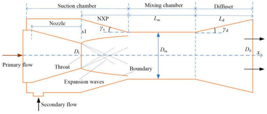
Figure 1.
A structure chart of a CO2 ejector.
The thermodynamic approach, the aerodynamic function method, and the CFD method are used to build the majority of models to forecast ejector performance. A CO2 ejector has a straightforward structure, yet it has an extremely intricate flow field. There are two broad types of two-phase flow models for CO2 ejectors: two-fluid and pseudo-fluid. Considering the average transport properties, the two phases can be regarded as a single pseudo-fluid in the pseudo-fluid approach. In contrast, the two-fluid method involves solving a series of calculations under each phase. The first type of pseudo-fluid model is the thermodynamic equilibrium, modeled as the HEM, and the other is the thermodynamic nonequilibrium. These models are categorized based on whether pseudo-fluid transport characteristics are evaluated. So far, only a few studies have assessed the velocity slip [17], and the majority of models presumptively assume homogenous flow.
2.1. HEM
The assumption behind the numerical model is that the local variables of velocity, pressure, and temperature are fixed for both the gas and liquid states of a single fluid. The HEM of the flow within the CO2 two-phase ejector is formulated as follows [18]:
where ρ is the density of fluid, u is the velocity vector, p is pressure, τ is the stress tensor, E is the total enthalpy, k is the effective thermal conductivity, and T is temperature.
In a thorough three-dimensional steady-state CFD model for a CO2 ejector, Smolka et al. [19] defined all properties in terms of pressure and total enthalpy. For activities near the critical point, the authors discovered that global characteristics such as the mass flow rate might be well estimated by the HEM method for activities near the critical point. The steady-state transport equation for any scalar has been formulated as follows:
where (~) denotes the Favre-averaged quantities, ϕ is the arbitrary scalar, Γeff is the effective diffusion coefficient, and Sϕ is the source term. When adding the scalar source phases into Equation (4), the following improved form of the transport Equation (5) is obtained:
where h is the specific enthalpy, and the source terms , , and describe the mechanical energy, irreversible kinetic energy dissipation, and turbulent kinetic energy dissipation, respectively. The built-in and revised energy formulations are used to determine the temperature and enthalpy fields, as illustrated in Figure 2 and Figure 3 [19]. The enthalpy in Figure 2a and Figure 3a was determined using the built-in solver, while that in Figure 2b and Figure 3b was suggested by the homogeneous model. Overall, both techniques yielded virtually equal specified range values for the parameters.
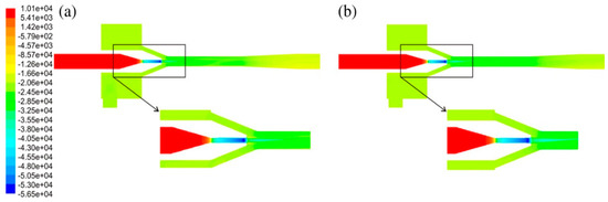
Figure 2.
The enthalpy (J kg−1) field inside the CO2 ejector. The enthalpy (J kg−1) was modelled using (a) a built-in solver and (b) the proposed homogenous model [19].
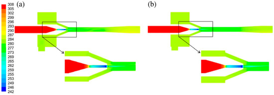
Figure 3.
The temperature field (k) inside the CO2 ejector. The enthalpy (J kg−1) was modelled using (a) a built-in solver and (b) the proposed homogenous model [19].
A comparable CO2 ejector model based on the HEM method was proposed by Lucas et al. [20]. Their study analyzed and compared the pressure recovery results by utilizing the outcomes of earlier experimental investigations. It was found that larger deviations between the experimental and simulation results were caused by the inaccuracy of the pressure loss model during the fluid mixing process. The parameter distribution revealed that the HEM is efficient and accurate for this condition. The applicability of the HEM technique under normal supermarket refrigerated situations was investigated by Palacz et al. [18]. The findings showed that the HEM method could accurately duplicate the experimental data, validating the accuracy of the ejector. The model predicts that under operating settings around or over the CO2 critical point, the lower the initial temperature, the shorter the distance to reach the saturation point, and the lower the accuracy of the corresponding model. Compared with the HEM implemented in ANSYS Fluent by Smolka [19], Giacomelli et al. [21] introduced a user-defined function to make the model more easily and quickly adaptable, which was different from the work of Smolka [19].
Bodys et al. [22] evaluated how fixed ejectors that had swirl flow at the entrance of the nozzles performed. For usage in supermarkets, CO2 refrigeration units are mounted in multi-ejector blocks. The results indicated that an appropriate primary flow rotational speed might boost ejector performance. Palacz et al. [23] proposed four CO2 ejector shape optimizations, where the objective of the optimization was to maximize ejector efficiency. Based on the HEM technique, an optimization algorithm was utilized in conjunction with a computational tool. Moreover, the flow field of the optimized device became more uniform due to momentum transfer. Figure 4 shows the pressure field of the basic design compared to the optimized design [23]. As is shown in Figure 4, the lowest pressure in the basic design was generated in the premixing chamber, whereas the lowest pressure in the optimized design occurred near the end of the motive nozzle. Additionally, Figure 5 shows an assessment of the intensity of the turbulence inside the basic and the optimized ejectors [23]. It can be observed from this that the turbulence intensity was the highest in the base ejector design near the wall side. Based on the theoretical studies of HEM, appropriate implementation of these technologies in real applications and heat pump systems was taken into consideration [24]. Liu et al. [25] simulated the CO2 ejector used for supermarket applications. The operational efficiency of the transcritical CO2 was analyzed by HEM. The outcomes demonstrated that the HEM was useful for predicting the power consumption of the CO2 ejectors.
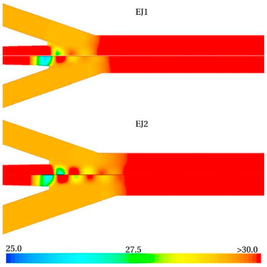
Figure 4.
The pressure field (Pa): the basic design of EJ1 and EJ2 is in the upper half and the optimized design is in the lower half [23].
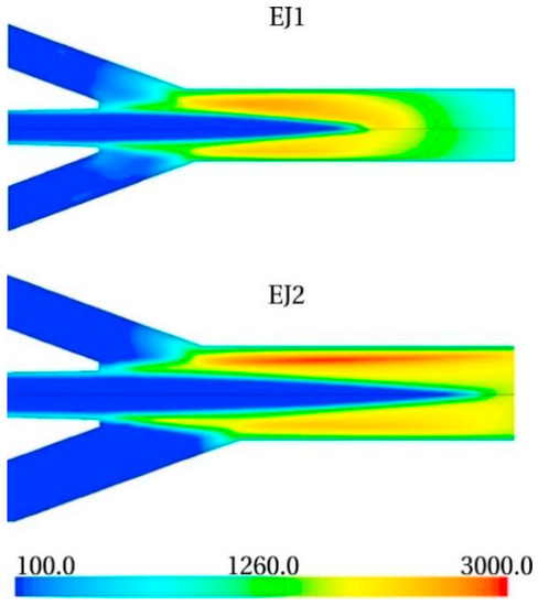
Figure 5.
The turbulence intensity [-]: the basic design of EJ1 and EJ2 is in the upper half and the optimized design is in the lower half [23].
Under supercritical conditions, the HEM has been extensively tested in the literature and is typically believed to generate findings that are quite accurate. Additionally, the simplification of the HEM is critical for the employment of optimization methods. Unfortunately, the model is not capable of depicting how the ejector works under low-pressure conditions and does not account for metastable flow.
2.2. HRM
The HRM was suggested by Bilicki [26], and the idea behind it arises from the inability to attain a transitory thermodynamic equilibrium between phases. In the model, this metastability is governed by a relaxation equation, as is shown in Equation (6), which treats the phase change as a relaxation process toward the equilibrium vapor quality [27].
where Γ is the vapor generation rate, θμ is the relaxation factor, is the mixture density, β is the instantaneous vapor mass fraction, and the time-averaged equilibrium vapor mass fraction. In HRM, nonequilibrium liquid–vapour transition is accounted for by a relaxation to thermodynamic equilibrium through the following equation for the vapour mass fraction:
where x is the dynamic vapour quality and θ is the relaxation time.
Haida et al. [27] also evaluated the flow of the dynamic nozzle, suction nozzle, premixing chamber, and mixing chamber at varied pre-relaxation time constants, increasing the calculation accuracy of the HRM method by about 5% compared to the HEM method. Figure 6 shows the outcomes.
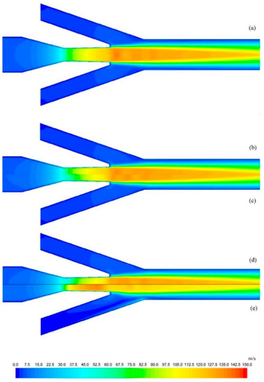
Figure 6.
Velocity field (m s−1) for (a) HEM and different relaxation time constants θ0 of (b) 10−6 s, (c) 10−5 s, (d) 10−4 s, and (e) 10−3 s [27].
The metastable events that occur during fluid expansion are not taken into consideration by the HEM, which causes the forecast error to rise as its accuracy decreases and the pressure and temperature fall, which has been argued for in previous ejector models [28]. The numerical model cannot incorporate metastable effects without the more complex two-phase flow model. In comparison to HEM, HRM takes into account metastable effects, which are applied to model the flow of the CO2 ejector. An HRM was later created by Angielczyk et al. for the CO2 flow in a two-phase ejector [28]. Compared to those predicted by HEM, the predicted velocity profiles are more in line with the experimental findings. The proposed relaxation time model has been implemented in the analysis of the nonequilibrium flow of the ejector:
where C is perimeter, and the relaxation time θ is included:
where θ0 is the relaxation time at the inlet temperature. a and b are empirical coefficients, α is the parameter for the mixture void fraction, ϕ is the pressure parameter, and x is the local instantaneous quality.
An HRM based on the relaxation parameters was proposed by Colombo et al. [29]. Their research showed that the modified HRM produced comparable precision to the HEM under supercritical operating conditions. Nonetheless, additional validation was required for investigations in a larger operating range. The Cramer method can be used to reduce the governing equations of the HRM. In this approach, Angielczyk et al. employed HRM to predict the critical flow of two-phase CO2 via the motive nozzle, and existing closure laws for relaxation time were adapted for CO2 flow [28]. The governing equation was as below:
In this case, the system of differential equations needs to be transformed into the following form:
where subscript ML is the metastable liquid fraction and l is an arbitrary parameter used as a new path variable of integration.
Colarossi et al. [30] applied the HRM approach to creating a 2D CFD model of a CO2 ejector. Examining the existence of nonequilibrium effects was the main goal of this investigation. The enthalpy near the diffuser (upper half) and the streak lines of the instantaneous velocity field (lower half) are shown in Figure 7. The high enthalpy of the gas mixes with the low enthalpy of the liquid at the beginning of the diffuser section. This mixing causes the vapor to condense. When the simulation was run for 0.3 s, vortices were formed due to the separation of the flow in the diffuser, which can be seen in the lower half of Figure 7 [30].
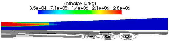
Figure 7.
The enthalpy (J kg−1) near the diffuser (upper half) and the streak lines of the instantaneous velocity field (lower half) [30].
The HRM and HEM techniques for CO2 ejectors were contrasted by Palacz et al. [31]. In the case of moving away from the critical point, the results revealed that HRM did better during the test when employing the constant relaxation time parameter proposed by Angielczyk et al. [28]. Overall, a 5% improvement in accuracy for HRM in the subcritical range was observed, but this improvement was insufficient. To get more precision, the relaxation time parameter has to be extensively investigated. The velocity distributions in the HEM and HRM motive nozzles are compared in Figure 8 [31]. The velocity near the nozzle throat was almost two times lower for the HRM case. In addition to velocity, the pressure field was examined. The HEM motive nozzle has a smoother distribution (the pressure distribution is more uniform and there is no mutation) than the HRM, as is shown in Figure 9 [31].
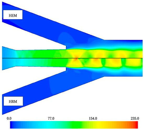
Figure 8.
The velocity fields in the motive nozzle and mixing chamber inlet for HEM (upper half) and HRM (lower half) [31].
Figure 9.
The pressure field in the motive nozzle and mixing chamber inlet for HEM (upper half) and HRM (lower half) [31].
An accurate turbulent flow model must first be constructed to simulate the internal mixing properties and flow field of the system accurately. Given the complexity of multi-phase turbulence and its distinctive thermophysical features, modeling turbulence flow in the CO2 ejector is more difficult than modeling single-phase flow. As a result, multi-phase turbulence is often neglected in current CO2 ejector models. For a two-phase HRM model, Haida et al. [27] linked the heat transmission inside the walls of a CO2 ejector and conducted an analysis of the covariates associated with various relaxation times. The best covariates for each relaxation time were determined using optimization techniques. They compared four turbulence models and suggested that more research into turbulence models be conducted. Bodys et al. [32] examined four cavitation events and turbulence models in the CO2 ejector. Using the considered turbulence model, the vapor distribution due to cavitation evaporation was described in the motive nozzle, and the effect of the turbulent form on the secondary flow characteristics in the mixing chamber was also explored. The relaxation and turbulence models are shown in Table 1.

Table 1.
Relaxation and turbulence models.
In general, an HRM uses CO2 equilibrium characteristics, much like an HEM, but adds a temporal delay that is dependent on the flow circumstances. An HRM is more accurate than an HEM at lower pressures (47–94 bar) and temperatures (6–36 °C).
2.3. Mixture Model
The equilibrium phase variation is the foundation of an HEM. However, the mixture model may represent the fluid characteristics under supercritical and metastable circumstances and describes nonequilibrium aspects. According to a comparison of the two models, the mixture model can forecast experimental findings more quickly and accurately than an HEM model, especially when it comes to mass flow prediction.
The flow within a CO2 two-phase ejector was modeled using a nonhomogeneous mixture, and the following equations were defined [17]:
where ρ and u represent the mixture density and averaged mass velocity, respectively, and E is the internal energy.
To simulate the flow of the nozzle in a CO2 ejector, Giacomelli et al. [36] presented a more detailed mixture model. To get a comprehensive set of thermodynamic flow characteristics for the two phases, NIST REFPROP [37] was used as the foundation for a look-up table.
where the two parameters σe and σc are two coefficients that are compared with the relaxation time and α is the volume fraction. The vapor and saturation characteristics are denoted by the subscript v and sat, respectively.
Furthermore, Giacomelli et al. [38] compared the HEM prediction results to those from the mixture model and discovered that the mixture model outperformed the HEM substantially, identifying a 19% error rate for the mixture model. Figure 10 depicts the density for the subcritical case with HEM and the mixture model [38]. The HEM has stronger shock waves at the motive nozzle exit and diffuser. According to Figure 11, the supercritical situation resulted in stronger shock and expansion waves [38]. Figure 12 depicts a comparison of the two cases according to vapor volume fraction, and a delayed phase change was apparent in it for subcritical processes [38].
Figure 10.
Contours of density for a subcritical situation: HEM (upper half) and mixture model (lower half) [38].
Figure 11.
Contours of density for the mixture model: supercritical (upper half) and subcritical cases (lower half) [38].
Figure 12.
Vapor volume fraction contour for the mixture model: supercritical case (upper half) and subcritical case (lower half) [38].
In addition to introducing a basic velocity slip model, Yazdani et al. [17] constructed a more realistic mixture model of a CO2 ejector than the HEM model. It was shown that the influence of the slip model on the overall effectiveness of the ejector was negligible. The relative velocity was used to calculate the drift velocity [11], which was the basis for the velocity slip and the relative velocity between a phase (p) and the mixture (m):
The velocity slip has a large impact on the shock wave pressure distribution, two-phase turbulence, and sound speed. Typically, velocity slip models only consider drag forces and ignore the interaction of the other two phases. Even so, a few research findings have taken velocity slip conditions into account.
The mixture model is capable of producing very accurate motive mass flow rates at supercritical pressures. Only a 2% error is observed for the motive mass flow rate [12]. The mixture model also evaluates more accurate phase variations via mass transfer and deals with the properties of gases and liquids under metastable conditions. However, low dynamic pressure testing has not been performed, and validation at low pressures is still pending due to a lack of a comprehensive literature database. Furthermore, mixture models increase the complexity and cost while necessitating additional model parameter adjustments.
2.4. DEM
In the DEM, metastable states in phase transitions are computationally investigated, which are particularly significant for calculating the critical mass flow rate of the primary flow for a certain motive nozzle design.
Based on the DEM, Banasiak et al. [39] developed differential equations along the CO2 ejector axis and then used the materiality equation to calculate the distribution of physical parameters in a one-dimensional CO2 two-phase ejector model. A set of ordinary differential equations, represented by the governing conservation equations, is shown below:
He et al. [40] created a 1D distribution model for a CO2 ejector and used the DEM to find the nonequilibrium phase change process in the nozzle. They then analyzed how the design of the ejector affected the performance and found that there was an optimal mixing chamber diameter for achieving higher efficiency and that when the mixing chamber diameter was known, a longer mixing chamber contributed to boosting the pressure lift ratio of the CO2 ejector. The DEM pressure distribution inside a converging–diverging nozzle has been examined by Angielczyk et al. [41]. Their findings indicate that the accuracy of the model is reduced by the introduction of nonequilibrium into the DEM.
Banasiak et al. [42] established a CO2 ejector by combining the DEM based on both homogeneous and heterogeneous nucleation theories. The CO2 expanding flow route was separated into three portions depending on the fluid thermodynamic condition and degree of thermal equilibrium.
In general, DEM considers the nonequilibrium phase change process, and the property equation is developed to represent the process. It should be noted that the two-phase sound speed should be studied in more detail, otherwise the robustness of the simulation is affected.
2.5. Shock Wave
Due to its complicated flow field characteristics, when CO2 diffuses from the super critical state to the two phases, it is likely to generate a shock wave, and the shock wave will have a significant influence on its operating performance due to its high-speed motion. To strengthen the effectiveness of the CO2 ejector cooling system, the shock waves have been examined. This is a research that has been concluded. To strengthen the effectiveness of the CO2 ejector cooling system, the shock waves are therefore being examined.
Most of the current research on shock waves in ejectors is based on a combination of theoretical analysis and experimental verification, and it is difficult to directly observe the presence of shock waves. Experimental studies of shock wave phenomena and properties in ejectors could provide further insights into their effects on ejector performance.
Berana et al. [43] investigated shock waves in a scaled nozzle of a CO2 ejector under various primary flow inlet conditions. The pressure drop could be well predicted with an equilibrium model prior to the shock waves, but a nonequilibrium model was required after the shock waves. That is why Berana et al. [43] suggested using an HRM to forecast the flow after the shock waves. The prediction of the ejector performance under various design parameters and non-design situations was carried out [44]. The findings have been verified with available data from the literature. Furthermore, He et al. [15] proposed an exergy analysis model, assuming a typical shock wave occurs at the entrance of the constant region. It should be noted that greater exergy losses occurred within the adjustable suction chamber of the ejector. This has been attributed to shock waves that were produced close to the needle, which reduced the entrainment effect and led to an entrainment ratio that was 5–11% lower.
To investigate the interior flow field of a shock wave, Lucas et al. [20] utilized a two-dimensional homogeneous model to numerically study a CO2 ejector and revealed that the pressure lift ratio was significantly influenced by the shock wave action at the motive nozzle exit. In order to characterize the development of the supersonic expansion wave, Zheng et al. [45] constructed a global mathematical model of the CO2 ejector. The diffuser and mixing chamber were modeled by a distribution parameter technique and a two-fluid model. The development of the shock wave in the suction chamber and its impact on the later mixing process were studied. Given the substantial influence of shock waves on the ejector performance, numerical simulations are necessary to determine the shock wave parameters at the ejector supersonic nozzle output and mixing chamber.
3. Optimization of Ejector Structure
The transcritical CO2 EERS performance enhancement is significantly influenced by the ejector structure characteristics. To forecast ejector performance indicators, Ringstad et al. [33] used a CFD simulation and trained a Gaussian process regression (GPR) machine learning model. In addition, for various ejector designs, the approach forecasts the local flow structure for pressure and velocity within the CO2 ejector to assess the performance of the ejector factors. Zheng et al. [46] combined experimental measurements and simulations. They discovered that as the area ratio and the nozzle exit position (NXP) increased, the efficiency of the components also increased. In an experimental study on the efficiency of ejectors [47], a novel mass balance ratio was implemented to assess the effectiveness of the system. The COP and entrainment ratio dropped as the liquid mass balance coefficient increased, and the ratio might be used to calculate the difference between the steady condition and the present operating condition.
In general, mainstream optimal methods and techniques for enhancing the ejector performance were suggested, including changing the geometry of the nozzle, controlling the throat cross area of the motive nozzle, adjusting the mixing chamber structure, and using multiple ejector combinations. Moreover, studies have been conducted to compare the benefits and drawbacks of the various optimization techniques. The configuration of the diffuser has less of an effect on the ejector performance than the mixing chamber design. Thus, the optimization process has not included this portion.
3.1. Change the Geometry of the Motive Nozzle
The geometry of the motive nozzle is the main factor that affects the efficiency of the CO2 ejector. Among them, the CO2 ejector is significantly influenced by the throat diameter of the motive nozzle, and the main flow rate of the CO2 ejector increases as the throat diameter of the motive nozzle increases, but the entrainment ratio decreases [48]. An adjustable CO2 ejector was investigated by Zheng et al. [46], in which the area of the motive nozzle and the NXP may both be changed using a needle. Then, the ejector performance and system characteristics were tested under various motive nozzle areas. After examining the motive nozzle of an adjustable CO2 ejector, Chen et al. [49] came to the conclusion that the efficiency of the nozzle was dependent on the type of working fluid, the working environment, and the design of the nozzle. A one-dimensional thermodynamic approach was suggested by Al-Tameemi et al. [13] to investigate the throat shape of an ejector. Moreover, the design parameters regarding nozzle geometry, area ratio, diameter, etc., were also derived. It was discovered that there was a shock wave at the motive nozzle exit. As the motive nozzle divergence angle rises, Huai et al. [50] experimentally analyzed the changing tendency of the entrainment ratio with fixed operating circumstances. Their research revealed that the COP of the system presented the opposite trend to the entrainment ratio of the CO2 ejector. When the throat of the motive nozzle was 2.00 mm in diameter and the diffusion angle of the first nozzle was 5° and 11°, the entrainment ratio and COP were at their highest. According to Liu et al. [51], the operating circumstances of CO2 two-phase ejectors have a considerable influence on their performance. The regulation and design of the ejector were essential for performance optimization, and the control system research and application of adjustable nozzle throat area regulation needed to be further expanded. He et al. [52] proposed an ideal controller for the CO2 ejector that was created to reach a maximum COP of about 3.155 by tracking the gas cooler pressure. Meanwhile, the optimal nozzle throat area is about 0.58 mm2, and the corresponding optimal gas cooler pressure is 11.2 MPa. The optimal controller is shown in Figure 13.
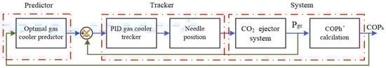
Figure 13.
The optimal controller for a transcritical CO2 refrigeration system with an adjustable ejector [52].
The adjustable throat area method is an effective method of adjusting the optimum high pressure for a given operating condition, and it could be realized by a needle in the motive nozzle, thereby improving the system’s performance.
3.2. Optimization of Mixing Chamber Structure
The CO2 ejector design and optimization require the consideration of other geometric parameters, particularly the dimensions. The turbulent mixing process causes the most irreversible losses, and the mixing chamber is the least efficient part of the device, demonstrating that the mixing chamber structure has a substantial influence on the ejector. Hence, in terms of optimizing the structure of the ejector, we also need to focus on the mixing section of the ejector.
Huang et al. [53] found the optimal mixing chamber lengths and diameters, 27 mm and 2.5 mm, producing an entrainment ratio close to 1.0. The structural characteristics of the mixing chamber had a big effect on how the shock wave properties changed. Lengthening the mixing chamber helped the length of the shock wave chain as long as its diameter remained constant, but as its length exceeded the optimal mixing chamber length, the strength of the shock wave gradually degraded. In addition, if the mixing chamber length remained constant, decreasing the mixing chamber diameter would result in a reduction in the amplitude of the shock wave at the motive nozzle exit and an increase in the shock wave at the diffuser inlet. To show that evaporation predominates the scintillation process in the CO2 ejector, Li et al. [16] employed a novel nonequilibrium evaporative cavitation CFD model to simulate the transient flow within the CO2 ejector. The geometric findings revealed that optimal mixing chamber diameters and lengths existed to improve the entrainment rates and that improperly sized mixing chambers could cause vortices or increased friction losses, reducing the entrainment ratio, secondary flow velocity, and mass flow rate.
To regulate the length of the mixing chamber while maintaining a constant mixing chamber diameter and other operational parameters, Zheng et al. [45] suggested an optimization approach that was computed for various expansion ratios. The velocity difference was initially reduced and subsequently grew as the length to diameter ratio of the mixing chamber increased while the expansion ratio of the ejector remained constant. The optimal mixing chamber length was achieved when there was little velocity differential between the two fluids, since this meant the two fluids were more thoroughly mixed. In the computed range, the ejector mixing chamber exhibited the best mixing uniformity and the smallest exit velocity difference when the length to diameter ratio was roughly 10.8 to 12.
Additional tests were conducted by Banasiak et al. [54] to evaluate the impact of the ejector mixing chamber. For their experimental conditions, the optimum mixing chamber diameter and length were obtained. However, these optimal structural parameters had to be matched to the operating parameters. The work carried out could be useful for the design of ejectors.
3.3. Method of Combining Multiple Ejectors
A single-geometry system has the drawback of being unable to successfully recover expansion work while also precisely managing the discharge pressure due to the limitation of constant ejector geometry. An alternate optimization strategy is a system with numerous ejectors in addition to sophisticated systems that manage the motive nozzle capacity and have great performance regardless of the operating circumstances. During their investigation, Haida et al. [55] employed several subcritical conditions and system loads, and the comparison demonstrated the significance of the multi-ejector block. The findings indicated that using a multi-ejector block could result in a 7% increase in the COP. As is shown in Figure 14 [56], a novel two-stage, the two-ejector transcritical CO2 refrigeration system was reported by Eskandari et al. [56]. In this study, each vapor compression line had its own ejector, so vapor compression was conducted in two steps.
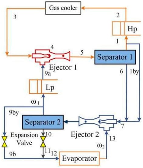
Figure 14.
Schematic of the novel two-stage, two-ejector transcritical CO2 refrigeration system [56].
A CO2 supermarket cooling system including dedicated mechanical subcooling and multiple ejectors (DMS + MEJ) was proposed by Liu et al. [57]. The yearly analysis also demonstrated that the DMS + MEJ system could increase the seasonal energy efficiency ratio by 42.73% in warm summer and mild winter zones while saving 29.94% in terms of energy. It was anticipated that the newly suggested system could replace the current CO2 supermarket booster refrigeration systems by significantly enhancing system performance and reducing energy consumption. Figure 15 provides a representation of the DMS + MEJ system [57].
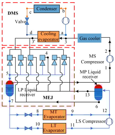
Figure 15.
An illustration of the DMS+MEJ system [57].
The effectiveness of a fixed CO2 ejector in a multi-ejector device installed in the cooling system was examined by Bodys et al. [58]. To investigate the operation of the module, a mean-order equilibrium model in a three-dimensional ejector model was considered. The multi-ejector module operated in seven configurations, each of which had a high cooling capacity and was suitable for industrial refrigeration installations. In all climates, commercial transcritical CO2 refrigeration systems have improved their position as market-ready options, according to Gullo et al. [59], who came to the conclusion that the multiple ejectors had contributed to this development. Moreover, a number of relevant installations have extensively demonstrated their dependability and viability, and their actual energy consumption has been monitored and reported.
For the refrigeration of supermarkets, Liu et al. [60] present their modified dual-ejector and dual-evaporator transcritical CO2 refrigeration cycle (MTRC) in Figure 16. Furthermore, the modified cycle had a flash tank and two ejectors in comparison to the traditional refrigeration cycle. When working in typical circumstances, the use of dual ejectors resulted in a 19.1% reduction in the compressor pressure ratio and 15.9–27.1% and 15.5–27.5% improvements in energy efficiency and COP, respectively, under different operational circumstances.
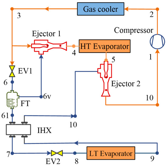
Figure 16.
The schematic diagram for the MTRC [60].
A two-temperature CO2 transcritical refrigeration cycle utilizing a two-cascade ejector was investigated by Bai et al. [61]. It was compared to different improved refrigeration systems. For the dual-ejector dual-temperature refrigeration cycle (DERC) shown in Figure 17 [61], to recover the expansion work done by the refrigerant in each stream, the gas cooler fluid may be separated into two streams using an extra ejector. This could improve the system efficiency and COP under different operating conditions.
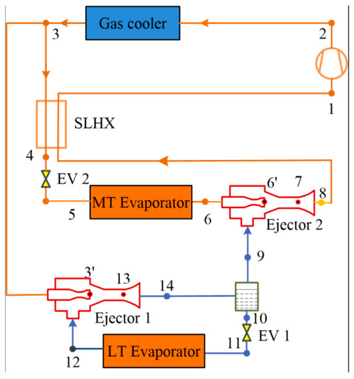
Figure 17.
The schematic diagram for the DERC [61].
Zou et al. [10] developed a dual ejector parallel transcritical CO2 cooling cycle, as shown in Figure 18 [10]. Additionally, they proposed an optimizing approach for fixed ejectors based on genetic algorithms. The dual ejector parallel system with enhanced ejector heating boosted its COP by 18% to 19.79% under heating conditions, and the system had better environmental adaptability.
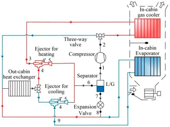
Figure 18.
The schematic diagram of a dual ejector parallel transcritical CO2 cooling cycle for an electric vehicle heat pump system [10].
Huang et al. [62] discovered that when the external temperature was below 17 °C, the conventional booster refrigeration system performed better than the booster refrigeration system with an ejector, and the opposite was true when the external temperature was above 17 °C. To maximize the system COP, the booster refrigeration system, shown in Figure 19 [62], was improved with two additional automatic control valves (ACV) before the fluid entered the ejector.
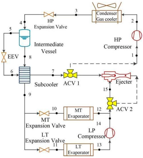
Figure 19.
The schematic diagram of a modified booster cooling system with a CO2 ejector [62].
4. Visualization Experiments with the CO2 Ejector
A corresponding experimental study of ejector performance on the CO2 ejector test rig was carried out in conjunction with the optimized design of the CO2 ejector, with the anticipated and experimental results showing excellent agreement. The present state of the experimental investigation of CO2 ejectors is examined in terms of how the structure of the ejector and the operating environment affect performance. By examining the system performance over the past 10 years, the intricate flow phenomena in the ejector have also drawn more and more attention. The complicated flow phenomena were investigated using flow visualization techniques.
Only the right ejector design and respective control approaches will allow for performance improvement. As a result, various groups of researchers have conducted many calculations on the properties of the flow of the fluids in the device. Unfortunately, there is not much experimental research on two-phase CO2, particularly with regard to the ability to visualize fluid movement. Berana et al. [43] explored shock wave forms in the CO2 two-phase flow in converging-diverging nozzles, but the images of the flow visualization did not show any shock waves. To determine the pressure distribution within the nozzle for six flow conditions, Li et al. [63] employed direct photography and pressure sensors to record the phase transition inside the motive nozzle of a CO2 ejector. This visualization experiment may serve as a roadmap for CO2 ejector geometry improvement and as input for CO2 ejector model validation. Furthermore, Li et al. [64] visualized the primary flow phase change and examined the impact of primary flow expansion on the entrainment rate. The nozzle pressure decreased with an increase in the nozzle diverging angles and the transition of primary flow from an under-expanded state to an overexpanded state when the diverging angle of the primary nozzle widened. The highest entrainment rate occurred at a 2.0° nozzle divergence angle, which was crucial for a thorough understanding of the main flow expansion process within a CO2 ejector. As illustrated in Figure 20, the visualization platform primarily consists of a light source, a visualization ejector, and a high-speed camera.
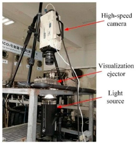
Figure 20.
Visualization test platform of CO2 ejector [64].
To observe the flow fields within the ejector under different operational circumstances, Zhu et al. [65] employed direct photography, as is shown in Figure 21. Under certain conditions, the mixing chamber inlet was blocked since the expansion angle was so large. Furthermore, the mixing chamber had a short mixing section for the mixed flow, so the mixed flow became homogeneous quickly.
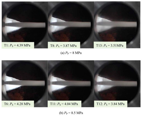
Figure 21.
Photographs of flows in the suction and mixing chamber [65].
Palacz et al. [66] concentrated on two-phase flows and mixing visualization testing within a CO2 ejector. As illustrated in Figure 22 [66], the experiment was performed on a CO2 vapor compression device that used a camera and multiple light sources to record the two-phase flow in the mixing section of the CO2 ejector.
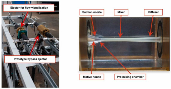
Figure 22.
CO2 ejector test (left) and transparent ejector mixing section (right) [66].
5. Conclusions
The application of a CO2 ejector greatly improves the energy utilization rate of CO2 vapor compression devices. Although this area of study is of great significance, it has not been reviewed comprehensively. This paper aims to improve the research on CO2 ejectors by comprehensively evaluating multi-phase flow modeling, turbulence characteristics, model applications and optimization, and visualization tests for flow fields in the ejector. The following main conclusions are drawn:
- (1)
- It is demonstrated that the HEM technique produces more accurate calculations for CO2 ejectors at supercritical operating conditions, whereas the HRM model improves model accuracy in terms of the mass entrainment ratio at lower temperatures and pressures by accounting for unbalanced phase changes. The DEM considers the nonequilibrium phase change to improve the model accuracy of a CO2 ejector. In Section 2 of this paper, we collect four different turbulence models to provide a summary chart that is able to compare the differences between these turbulence models.
- (2)
- The numerical analysis enables a detailed analysis of the operating processes within the ejector and the optimized design of its overall performance. The mainstream optimal methods and techniques were presented to enhance ejector efficiency. In this section, the effects of the motive nozzle, mixing chamber structure, and multiple ejectors on the performance of CO2 ejectors are investigated in terms of their structural dimensions. The adjustable throat area method is an effective method for adjusting the optimum high pressure. In the mixing chamber, the turbulent mixing procedure causes the greatest irreversible losses, which means that the performance of the mixing chamber is significantly impacted by its structural design. Using multiple ejectors could flexibly and effectively manage the discharge pressure and revive the expansion work.
- (3)
- This paper also investigates the flow field in the nozzle of a CO2 ejector. The results of this study show that the supersonic flow of fluid within the ejector causes irreversible processes such as shock waves and such irreversible processes can have an impact on the operating characteristics of the ejector. The importance of surge waves in the nozzle is emphasized by observing the flow field within the injector under different operating conditions in a visualization experiment of the CO2 ejector, which investigates the effect of surge waves on the injector entrainment rate and the injector cooling system.
However, further research and development are required in these areas since the design and execution of the CO2 ejector still have a lot of new issues to resolve and need to be gathered and improved in actual applications. The focus should be shifted from the external structure of the ejector to the complex internal flow, with a particular emphasis on the consequences of two-phase turbulence. The whole ejector design should be the focus of future ejector optimization operations.
Author Contributions
Conceptualization, L.Z., Y.Z. and H.L.; methodology, L.Z., Y.Z. and H.L.; software, L.Z., J.D. and Y.Z.; validation, L.Z., Y.Z. and L.H.; formal analysis, L.Z., Y.Z. and L.H.; investigation, L.Z., J.D. and Y.Z.; data curation, L.Z. and Y.Z.; writing—original draft preparation, L.Z., Y.Z. and W.L.; writing—review and editing, L.Z., Y.Z. and W.L.; supervision, L.Z. and W.L.; project administration, L.Z. and W.L.; funding acquisition, L.Z. and W.L. All authors have read and agreed to the published version of the manuscript.
Funding
This research was funded by The National Natural Science Foundation of China, grant numbers 51806132, 52274222, 51806131, and 51366001.
Data Availability Statement
The data presented in this study are available upon reasonable request from the corresponding author.
Conflicts of Interest
The authors declare no conflict of interest.
References
- Bellos, E.; Tzivanidis, C. A comparative study of CO2 refrigeration systems. Energy Convers. Manag. 2019, 1, 100002. [Google Scholar] [CrossRef]
- Yu, B.B.; Yang, J.Y.; Wang, D.D.; Shi, J.Y.; Chen, J.P. An updated review of recent advances on modified technologies in transcritical CO2 refrigeration cycle. Energy 2019, 189, 116147. [Google Scholar] [CrossRef]
- Nebot-Andrés, L.; Del Duca, M.G.; Aprea, C.; Zerovnik, A.; Tusek, J.; Llopis, R.; Maiorino, A. Improving efficiency of transcritical CO2 cycles through a magnetic refrigeration subcooling system. Energy Convers. Manag. 2022, 265, 115766. [Google Scholar] [CrossRef]
- Thongtip, T.; Aphornratana, S. Impact of primary nozzle area ratio on the performance of ejector refrigeration system. Appl. Therm. Eng. 2021, 188, 116523. [Google Scholar] [CrossRef]
- Ghazizade-Ahsaee, H.; Askari, I.B. The application of thermoelectric and ejector in a CO2 direct-expansion ground source heat pump; energy and exergy analysis. Energy Convers. Manag. 2020, 226, 113526. [Google Scholar] [CrossRef]
- Deng, J.Q.; Jiang, P.X.; Lu, T.; Lu, W. Particular characteristics of transcritical CO2 refrigeration cycle with an ejector. Appl. Therm. Eng. 2007, 27, 381–388. [Google Scholar] [CrossRef]
- Zhu, Y.; Huang, Y.; Li, C.; Zhang, F.; Jiang, P.X. Experimental investigation on the performance of transcritical CO2 ejector–expansion heat pump water heater system. Energy Convers. Manag. 2018, 167, 147–155. [Google Scholar] [CrossRef]
- Santini, F.; Bianchi, G.; Di Battista, D.; Villante, C.; Orlandi, M. Experimental investigations on a transcritical CO2 refrigeration plant and theoretical comparison with an ejector-based one. Energy Procedia 2019, 161, 309–316. [Google Scholar] [CrossRef]
- Pérez, B.P.; Carrillo, J.; Flor, F.; Lissen, J.; Navarro, A.M. Thermoeconomic analysis of CO2 ejector-expansion refrigeration cycle (EERC) for low-temperature refrigeration in warm climates. Appl. Therm. Eng. 2021, 188, 116613. [Google Scholar] [CrossRef]
- Zou, H.; Yang, T.; Tang, M.; Tian, C.; Butrymowicz, D. Ejector optimization and performance analysis of electric vehicle CO2 heat pump with dual ejectors. Energy 2022, 239, 122452. [Google Scholar] [CrossRef]
- Ringstad, K.E.; Allouche, Y.; Gullo, P. A detailed review on CO2 two-phase ejector flow modeling. Therm. Sci. Eng. Prog. 2022, 20, 100647. [Google Scholar] [CrossRef]
- Yu, F.; Poncet, S.; Nesreddine, H.; Bartosiewicz, Y. An open-source density-based solver for two-phase CO2 compressible flows: Verification and validation. Int. J. Refrig. 2019, 106, 526–538. [Google Scholar]
- Al-Tameemi, M.R.J.; Yu, Z. Thermodynamic approach for designing the two-phase motive nozzle of the ejector for transcritical CO2 heat pump system. Energy Procedia 2017, 142, 1206–1212. [Google Scholar] [CrossRef]
- He, Y.; Deng, J.Q.; Li, Y.F.; Zhang, X.P. Synergistic effect of geometric parameters on CO2 ejector based on local exergy destruction analysis. Appl. Therm. Eng. 2021, 184, 116256. [Google Scholar] [CrossRef]
- He, Y.; Deng, J.Q.; Li, Y.F.; Ma, L. A numerical contrast on the adjustable and fixed transcritical CO2 ejector using exergy flux distribution analysis. Energy Convers. Manag. 2019, 196, 729–738. [Google Scholar] [CrossRef]
- Li, Y.F.; Deng, J.Q. Numerical investigation on the performance of transcritical CO2 two-phase ejector with a novel non-equilibrium CFD model. Energy 2022, 238, 121995. [Google Scholar] [CrossRef]
- Yazdani, M.; Alahyari, A.A.; Radcliff, T.D. Numerical modeling of two-phase supersonic ejectors for work-recovery applications. Int. J. Heat Mass Transf. 2012, 55, 5744–5753. [Google Scholar] [CrossRef]
- Palacz, M.; Smolka, J.; Fic, A.; Bulinski, Z. Application range of the HEM approach for CO2 expansion inside two-phase ejectors for supermarket refrigeration systems. Int. J. Refrig. 2015, 59, 251–258. [Google Scholar] [CrossRef]
- Smolka, J.; Bulinski, Z.; Fic, A.; Nowak, A.J.; Banasiak, K.; Hafner, A. A computational model of a transcritical R744 ejector based on a homogeneous real fluid approach. Appl. Math. Model. 2013, 37, 1208–1224. [Google Scholar] [CrossRef]
- Lucas, C.; Rusche, H.; Schroeder, A.; Koehleret, J. Numerical investigation of a two-phase CO2 ejector. Int. J. Refrig. 2014, 43, 154–166. [Google Scholar] [CrossRef]
- Giacomelli, F.; Banasiak, K.; Hafner, A.; Mazzelli, F.; Milazzo, A. Experimental and numerical investigation on a ejector for CO2 vapor compression systems. In Proceedings of the 13th IIR Gustav Lorentzen Conference, Valencia, Spain, 18–20 June 2018. [Google Scholar]
- Bodys, J.; Smolka, J.; Palacz, M.; Haida, M.; Banasiak, K.; Nowak, A.T.; Hafner, A. Performance of fixed geometry ejectors with a swirl motion installed in a multi-ejector module of a CO2 refrigeration system. Energy 2016, 117, 620–631. [Google Scholar] [CrossRef]
- Palacz, M.; Smolka, J.; Nowak, A.J.; Banasiak, K.; Hafneret, A. Shape optimisation of a two-phase ejector for CO2 refrigeration systems. Int. J. Refrig. 2017, 74, 212–223. [Google Scholar] [CrossRef]
- Gullo, P.; Hafner, A.; Banasiak, K. Transcritical R744 refrigeration systems for supermarket applications. Curr. Status Future Perspect. 2018, 93, 269–310. [Google Scholar]
- Liu, G.D.; Wang, Z.; Zhao, H.X.; Ali Abdulwahid, A. R744 ejector simulation based on homogeneous equilibrium model and its application in trans-critical refrigeration system. Appl. Therm. Eng. 2022, 201, 117791. [Google Scholar] [CrossRef]
- Bilicki, Z.; Kestin, J. Physical aspects of the relaxation model in two-phase flow. Math. Phys. Sci. 1990, 428, 379–397. [Google Scholar]
- Haida, M.; Smolka, J.; Hafner, A.; Palacz, M.; Banasiak, K.; Nowak, A.J. Modified homogeneous relaxation model for the R744 trans-critical flow in a two-phase ejector. Int. J. Refrig. 2018, 85, 314–333. [Google Scholar] [CrossRef]
- Angielczyk, W.; Bartosiewicz, Y.; Butrymowicz, D.; Seynhaeve, J.M. 1-D modeling of supersonic carbon dioxide two-phase flow through ejector motive nozzle. In Proceedings of the International Refrigeration and Air Conditioning Conference, Purdue, IN, USA, 12–15 July 2010. [Google Scholar]
- Colombo, A.; Conti, P.; Orlandi, M. CFD simulations of a two-phase ejector for transcritical CO2 cycles applied to supermarket refrigeration systems. In Proceedings of the 13th IIR Gustav Lorentzen Conference, Valencia, Spain, 18–20 June 2018. [Google Scholar]
- Schmidt, D.; Colarossi, M.; Bergander, M.J. Multidimensional modeling of condensing two-phase ejector flow. In Proceedings of the International Seminar on Ejector/Jet Pump Technology and Applications, Louvain-la-Neuve, Belgium, 7–9 September 2009. [Google Scholar]
- Palacz, M.; Haida, M.; Smolka, J.; Nowak, A.J.; Banasiak, K.; Hafner, A. HEM and HRM accuracy comparison for the simulation of CO2 expansion in two-phase ejectors for supermarket refrigeration systems. Appl. Therm. Eng. 2017, 115, 160–169. [Google Scholar] [CrossRef]
- Bodys, J.; Smolka, J.; Palacz, M.; Haida, M.; Banasiak, K.; Nowak, A.J. Effect of turbulence models and cavitation intensity on the motive and suction nozzle mass flow rate prediction during a non-equilibrium expansion process in the CO2 ejector. Appl. Therm. Eng. 2022, 201, 117743. [Google Scholar] [CrossRef]
- Ringstad, K.E.; Banasiak, K.; Ervik, A.; Hafner, A. Machine learning and CFD for mapping and optimization of CO2 ejectors. Appl. Therm. Eng. 2021, 199, 117604. [Google Scholar] [CrossRef]
- Menter, F.R.; Kuntz, M.; Langtry, R. Ten years of industrial experience with the SST turbulence model. Heat Mass Transf. 2003, 4, 625–632. [Google Scholar]
- Bartosiewicz, Y.; Aidoun, Z.; Mercadier, Y. Numerical assessment of ejector operation for refrigeration applications based on CFD. Appl. Therm. Eng. 2006, 26, 604–612. [Google Scholar] [CrossRef]
- Giacomelli, F.; Mazzelli, F.; Milazzo, A. A novel CFD approach for the computation of R744 flashing nozzles in compressible and metastable conditions. Energy 2018, 162, 1092–1105. [Google Scholar] [CrossRef]
- Song, Y.; Ma, Y.; Wang, H.; Yin, X.; Cao, F. Review on the simulation models of the two-phase-ejector used in the transcritical carbon dioxide systems. Int. J. Refrig. 2020, 119, 434–447. [Google Scholar] [CrossRef]
- Giacomelli, F.; Mazzelli, F.; Banasiak, K.; Hafner, A.; Milazzo, A. Experimental and computational analysis of a R744 flashing ejector. Int. J. Refrig. 2019, 107, 326–343. [Google Scholar] [CrossRef]
- Banasiak, K.; Hafner, A. 1D Computational model of a two-phase R744 ejector for expansion work recovery. Int. J. Therm. Sci. 2011, 50, 2235–2247. [Google Scholar] [CrossRef]
- He, Y.; Zhang, Z.X.; Xue, C.L.; Yang, Y.Z.; Deng, J.Q. A CO2 two-phase ejector model based on delayed equilibrium model. J. Refrig. 2016, 37, 1–6. [Google Scholar]
- Angielczyk, W.; Seynhaeve, J.M.; Gagan, J.; Bartosiewicz, Y.; Butrymowicz, D. Prediction of critical mass rate of flashing carbon dioxide flow in convergent-divergent nozzle. Chem. Eng. Process. Process Intensif. 2019, 143, 107599. [Google Scholar] [CrossRef]
- Banasiak, K.; Hafner, A. Mathematical modelling of supersonic two-phase R744 flows through converging–diverging nozzles: The effects of phase transition models. Appl. Therm. Eng. 2013, 51, 635–643. [Google Scholar] [CrossRef]
- Berana, M.S.; Nakagawa, M.; Harada, A. Shock waves in supersonic two-phase flow of CO2 in converging-diverging nozzles. HVACR Res. 2009, 15, 1081–1098. [Google Scholar] [CrossRef]
- Taleghani, S.T.; Sorin, M.; Poncet, S. Modeling of two-phase transcritical CO2 ejectors for on-design and off-design conditions. Int. J. Refrig. 2018, 87, 91–105. [Google Scholar] [CrossRef]
- Zheng, L.X.; Hu, H.W.; Wang, W.B.; Zhang, Y.Y.; Wang, L.M. Study on Flow Distribution and Structure Optimization in a Mix Chamber and Diffuser of a CO2 Two-Phase Ejector. Mathematics 2022, 10, 693. [Google Scholar] [CrossRef]
- Zheng, L.X.; Deng, J.Q. Research on CO2 ejector component efficiencies by experiment measurement and distributed-parameter modeling. Energy Convers. Manag. 2017, 142, 244–256. [Google Scholar] [CrossRef]
- Zhu, Y.H.; Li, C.H.; Zhang, F.Z.; Jiang, P.X. Comprehensive experimental study on a transcritical CO2 ejector-expansion refrigeration system. Energy Convers. Manag. 2017, 151, 98–106. [Google Scholar] [CrossRef]
- Haberschill, P.; Nehdi, E.; Kairouani, L. Experimental study of a two-phase ejector for CO2 transcritical refrigeration system. Arch. Thermodyn. 2021, 42, 217–246. [Google Scholar]
- Chen, J.; Li, Y.; Chen, W.; Luo, X.; Ying, C.; Yang, Z.; Eames, I.W. Investigation of the ejector nozzle in refrigeration system. Energy 2018, 157, 571–587. [Google Scholar] [CrossRef]
- Huai, Y.S.; Guo, X.M.; Shi, Y.G. Experimental Study on Performance of Double-throttling Device Transcritical CO2 Ejector Refrigeration System. Energy Procedia 2017, 105, 5106–5113. [Google Scholar] [CrossRef]
- Liu, Y.F.; Yu, J.; Wu, Q. Current status of research on CO2 heat pump/cooling system with ejector. Build. Energy Effic. 2017, 46, 64–69, 78. [Google Scholar]
- He, Y.; Deng, J.Q.; Zheng, L.X.; Zhang, Z.X. Performance optimization of a transcritical CO2 refrigeration system using a controlled ejector. Int. J. Refrig. 2017, 75, 250–261. [Google Scholar] [CrossRef]
- Huang, H.L.; Liu, H.; Li, G. Performance optimization of transcritical CO2 ejectors based on boiling cavitation model. J. Sol. Energy 2020, 41, 233–240. [Google Scholar]
- Banasiak, K.; Hafner, A.; Andresen, T. Experimental and numerical investigation of the influence of the two-phase ejector geometry on the performance of the R744 heat pump. Int. J. Refrig. 2012, 35, 1617–1625. [Google Scholar] [CrossRef]
- Haida, M.; Banasiak, K.; Smolka, J.; Hafner, A.; Eikevik, T.M. Experimental analysis of the R744 vapor compression rack equipped with the multi-ejector expansion work recovery module. Int. J. Refrig. 2016, 64, 93–107. [Google Scholar] [CrossRef]
- Eskandari, M.F.; Cheraghi, M. Performance of a new two-stage transcritical CO2 refrigeration cycle with two ejectors. Appl. Therm. Eng. 2019, 156, 402–409. [Google Scholar] [CrossRef]
- Liu, X.; Yu, K.; Wan, X.; Li, X. Performance evaluation of CO2 supermarket refrigeration system with multi-ejector and dedicated mechanical subcooling. Energy Rep. 2021, 7, 5214–5227. [Google Scholar] [CrossRef]
- Bodys, J.; Palacz, M.; Haida, M.; Smolka, J.; Nowak, A.J.; Banasiak, K.; Hafner, A. Full-scale multi-ejector module for a carbon dioxide supermarket refrigeration system: Numerical study of performance evaluation. Energy Convers. Manag. 2017, 138, 312–326. [Google Scholar] [CrossRef]
- Gullo, P.; Hafner, A.; Banasiak, K.; Minetto, S. Multi-ejector concept: A comprehensive review on its latest technological developments. Energies 2019, 12, 406. [Google Scholar] [CrossRef]
- Liu, J.; Liu, Y.; Yu, J. Performance analysis of a modified dual-ejector and dual-evaporator transcritical CO2 refrigeration cycle for supermarket application. Int. J. Refrig. 2021, 131, 109–118. [Google Scholar] [CrossRef]
- Bai, T.; Yan, G.; Yu, J. Performance evolution on a dual-temperature CO2 transcritical refrigeration cycle with two cascade ejectors. Appl. Therm. Eng. 2017, 120, 26–35. [Google Scholar] [CrossRef]
- Huang, Z.; Zhao, H.; Yu, Z.; Han, J. Simulation and optimization of a R744 two-temperature supermarket refrigeration system with an ejector. Int. J. Refrig. 2018, 90, 73–82. [Google Scholar] [CrossRef]
- Li, Y.F.; Deng, J.Q.; Ma, L.; Zhang, Y.Z. Visualization of two-phase flow in primary nozzle of a transcritical CO2 ejector. Energy Convers. Manag. 2018, 171, 729–741. [Google Scholar] [CrossRef]
- Li, Y.F.; Deng, J.Q.; Ma, L. Experimental study on the primary flow expansion characteristics in transcritical CO2 two-phase ejectors with different primary nozzle diverging angles. Energy 2019, 186, 115839. [Google Scholar] [CrossRef]
- Zhu, Y.; Wang, Z.; Yang, Y.; Jiang, P.X. Flow visualization of supersonic two-phase transcritical flow of CO2 in an ejector of a refrigeration system. Int. J. Refrig. 2017, 74, 354–361. [Google Scholar] [CrossRef]
- Palacz, M.; Bodys, J.; Haida, M. Two-phase flow visualisation in the R744 vapor ejector for refrigeration systems. Appl. Therm. Eng. 2022, 210, 118322. [Google Scholar] [CrossRef]


Publisher’s Note: MDPI stays neutral with regard to jurisdictional claims in published maps and institutional affiliations. |
© 2022 by the authors. Licensee MDPI, Basel, Switzerland. This article is an open access article distributed under the terms and conditions of the Creative Commons Attribution (CC BY) license (https://creativecommons.org/licenses/by/4.0/).