Article

Adaptive Sensorless PI+Passivity-Based Control of a Boost Converter Supplying an Unknown CPL

by
Sebastián Riffo
1,*,
Walter Gil-González
2,
Oscar Danilo Montoya
3,4,
Carlos Restrepo
1,5,* and
Javier Muñoz
4,*
1
Department of Electrical Engineering, Universidad de Talca, Curicó 3340000, Chile
2
Department of Electrical Engineering, Universidad Tecnológica de Pereira, Pereira 660003, Colombia
3
Grupo de Compatibilidad e Interferencia Electromagnética, Facultad de Ingeniería, Universidad Distrital Francisco José de Caldas, Bogotá 110231, Colombia
4
Laboratorio Inteligente de Energía, Facultad de Ingeniería, Universidad Tecnológica de Bolívar, Cartagena 131001, Colombia
5
Principal Investigator Millenium Institute on Green Ammonia as Energy Vector (MIGA), Santiago de Chile 7820436, Chile
*
Authors to whom correspondence should be addressed.
Mathematics 2022, 10(22), 4321; https://doi.org/10.3390/math10224321
Submission received: 15 October 2022 / Revised: 7 November 2022 / Accepted: 10 November 2022 / Published: 17 November 2022
(This article belongs to the Special Issue Dynamic Modeling and Simulation for Control Systems)

Abstract

:
This paper presents an adaptive control to stabilize the output voltage of a DC–DC boost converter that feeds an unknown constant power load (CPL). The proposed controller employs passivity-based control (PBC), which assigns a desired system energy to compensate for the negative impedance that may be generated by a CPL. A proportional-integral (PI) action that maintains a passive output is added to the PBC to impose the desired damping and enhance disturbance rejection behavior, thus forming a PI+PBC control. In addition, the proposed controller includes two estimators, i.e., immersion and invariance (I&I), and disturbance observer (DO), in order to estimate CPL and supply voltage for the converter, respectively. These observers become the proposed controller for an adaptive, sensorless PI+PBC control. Phase portrait analysis and experimental results have validated the robustness and effectiveness of the adaptive proposed control approach. These results show that the proposed controller adequately regulates the output voltage of the DC–DC boost converter under variations of the input voltage and CPL simultaneously.

1. Introduction

1.1. General Context

Recent advances in electrical distribution networks with DC technologies for medium and low-voltage applications have boosted the massive integration of multiple distributed energy resources, such as renewable generation [1], energy storage systems [2], and controllable loads [3], among others. The main characteristic of integrating these devices in DC networks is the need to use power electronic converters to manage their behavior and take each one of them to an optimal operating point [4]. Figure 1 presents most of the typical DC–DC converters used to interface distributed energy resources and controllable loads to a DC bus.
Note that the technology of the converter will depend exclusively on the distributed energy resource it interfaces. In the case of solar and wind sources, the converter is unidirectional, and it may be a buck or boost converter [5]. Battery energy storage systems must be bidirectional in nature, as the battery behaves as a load in some periods and as a power supply in others [6]. For this reason, bidirectional boost converters constitute an alternative to manage energy behavior in batteries. In the case of controllable loads (linear or nonlinear), the energy flow goes from the DC bus to the load, which implies that a buck or boost converter can be used to integrate them into the DC network.
In Figure 1, it is evident that power electronic converters play the most important role in the massive integration of distributed energy resources and loads into DC networks. This implies that advanced control techniques are required to manage energy requirements effectively.

1.2. Motivation

The power electronic converters presented in Figure 1 pose important challenges to the operation of entire DC grids, given that efficient methodologies are needed to control the DC system at primary, secondary, and tertiary levels. The primary control design is the first layer that associates the system’s behavior with its physical devices, i.e., this control stage is entrusted with operating each converter. It is necessary to consider the system’s physical requirements regarding its response speed while ensuring a stable behavior under normal operating conditions [7]. The secondary control is also known as restorative control, which aims to stabilize the operation of the DC network under abnormal conditions, i.e., temporary short-circuit or load disconnections, with the main purpose of preserving all the state variables within a secure range of operation [8]. On the other hand, the tertiary control stage, also known as the optimization stage, is entrusted with defining the operative conditions of the network (signal references) in order to minimize or maximize some performance indicators [9].
The main interest of this research corresponds to the primary control design for a converter that interfaces the DC network with an energy user. Specifically, it focuses on designing a controller for a boost converter to support the voltage profile of a constant power load at the terminals while assuming that the voltage of the DC network and the value of the constant power consumption are unknown. This is a critical problem in microgrid energy management systems, as it is necessary to design an efficient controller that ensures the stable operation of the load and grid under normal operating conditions [10]. However, this is a challenging control task, given the nonlinearities introduced by the load (negative impedance) and that the boost converter has a nonlinear model [11,12]. Due to the above, it is important to study nonlinear controls that include estimators for the external inputs to the system, guaranteeing its stability [13,14,15].

1.3. Literature Review

Multiple studies on control methods implemented in boost converters have been presented in the specialized literature. Stability analysis for a boost converter supplied a constant power load (CPL) was proposed by [16]. A robust sliding mode control based on pulse-width modulation was described in [17] in order to remove possible instabilities provided by the CPL in DC microgrids. An adaptive backstepping sliding mode control to regulate the output voltage of a boost converter connected to a CPL was proposed in [18]. A sliding mode control to manage the output voltage of a boost converter feeding a CPL was presented in [19], where the authors employed a switching surface that relieves the inrush current in the boost converter and external disturbances by maintaining its output voltage at the desired value. Incremental passivity-based control (PBC) was presented in [20,21] to stabilize the output voltage of a DC–DC converter under time-varying disturbances, which were addressed by implementing a proportional-integral (PI) observer. In [22], a robust type-II fuzzy technique based on pulse-width modulation was presented to control a DC–DC boost converter with a CPL. The authors of [23] designed a controller to regulate the output voltage of a DC–DC boost converter feeding a CPL. This controller was based on a sliding mode control method and included a finite-time parameter observer. An adaptive output feedback control to maintain the output voltage of a DC–DC boost converter was shown in [24]. This control added an estimate for the converter’s inductor current and load conductance based on a reduced-order state observer. The study by [25] designed a PI-PBC method to ensure that the output voltage of a DC–DC boost converter remained at the desired value. This method included a parameter estimation-based observer for the converter inductor current. Finally, the authors of [26] presented a nonlinear control based on the interconnection and damping assignment (IDA) PBC strategy to regulate the output voltage of a boost-type DC–DC converter.

1.4. Contribution and Scope

Considering the aforementioned literature review, this research article makes the following contributions:
i.
The formulation of a general nonlinear control design based on PBC theory, which regulates the voltage at the terminals of an unknown constant power load fed by a boost converter.
ii.
The addition of a PI design that maintains passive output to improve the convergence of the proposed control and remove the oscillations generated by the disturbance.
iii.
The combination of the immersion and invariance (I&I) and disturbance observer techniques to estimate the CPL and input voltage of the converter with the proposed controller, thus making it an adaptive, sensorless PI+PBC control, as verified by the simulation and experiment results.
The main advantage of the proposed PBC design, which includes PI action, is that it ensures the asymptotic stable operation of the boost converter, taking into account that its input voltage, as well as the CPL values, are estimated in real-time (online). This is particularly important because the control law in closed-loop operation is independent of physical measures, namely the voltage input and load current. This approach reduces the number of sensors required.

1.5. Document Organization

The remainder of this document is structured as follows: the mathematical modeling of the DC–DC boost converter using averaging modeling theory and control problem formulations is presented in Section 2. The design of the proposed adaptive controller with the inclusion of the estimator is described in Section 3. Section 4 presents the phase portrait analysis and experimental results used to validate the proposed controller. Finally, Section 5 lists the main conclusions of this research.

2. Mathematical Modeling and Problem Formulation

This section uses averaging modeling theory to describe the general mathematical modeling of the boost converter feeding a constant power load. It also presents the equilibrium point for this system, which is essential in designing any control approach. In addition, the control problem formulation and the requirements for the voltage regulation of the studied converter are defined.

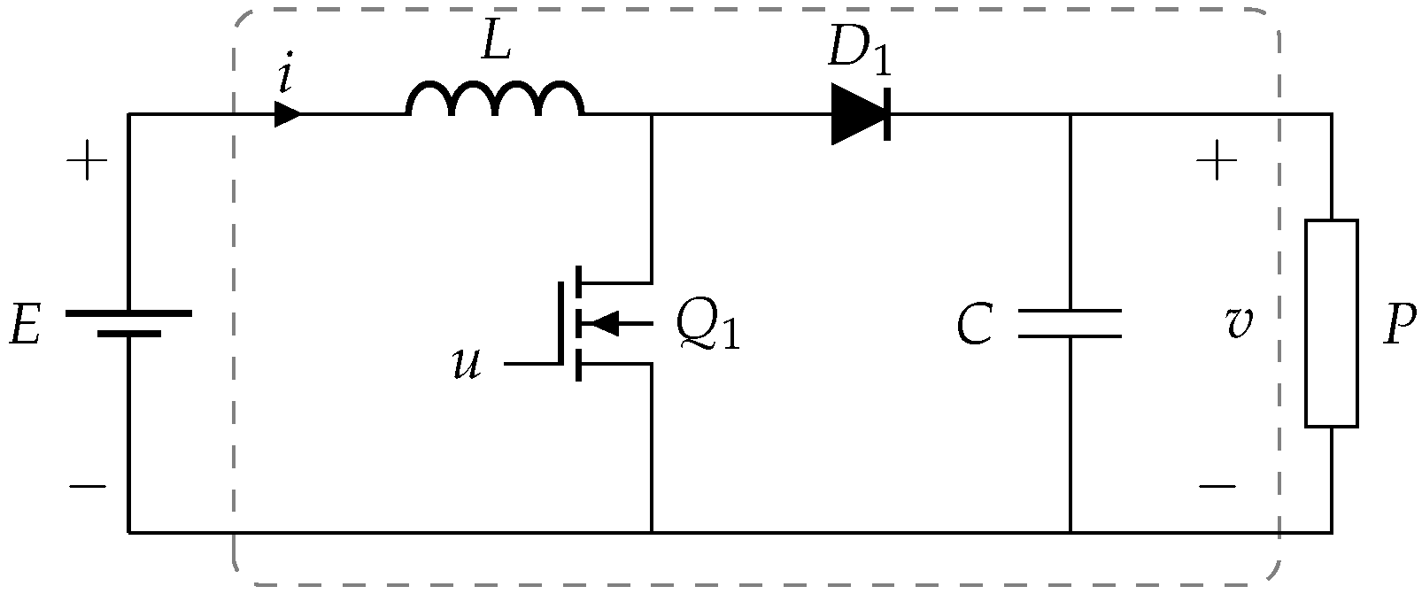
2.1. DC–DC Boost Converter Modeling

A boost converter is a DC–DC converter whose voltage output has a higher DC value than its input voltage, which makes it a step-up converter. A boost converter is composed of two semiconductor switches (diode and IGBT) and two elements for energy storage, namely the capacitor and the inductor [27]. Figure 2 illustrates a boost converter supplying a CPL. Its dynamic model is achieved using two of Kirchhoff’s laws. The second law is applied at node, which connects the capacitor, inductor, and IGBT. In contrast, Kirchhoff’s first law is applied to the closed-loop trajectory that contains the inductor, thus generating its dynamic model:
L i ˙ = 1 u v + E , C v ˙ = 1 u i P v ,
where i , v , E R > 0 are the inductor current, output voltage, and input voltage, respectively. P R > 0 is the CPL, u [ 0 , 1 ] is the control input, and L , C R > 0 are inductance and capacitance values, respectively.
The determination of the equilibrium point for the boost converter (1) is straightforward:
ε : = ( i , v ) R > 0 2 | i E P = 0 .

2.2. Control Problem Formulation

The control challenges for the dynamic model (1) lie in the extracted power load P and input voltage E, which are assumed to be unknown. Hence, the aims of the proposed controller are:
i.
To design a control law in order to regulate the output voltage v at the desired equilibrium point v ;
ii.
To develop an observer to estimate the value of the CPL which achieves an adaptive control;
iii.
To propose an estimator for the input voltage E in order to obtain a sensorless control scheme.
For the sake of simplicity, defining x 1 : = i , x 2 : = v yields the following:
L x 1 ˙ = ( 1 u ) x 2 + E , C x 2 ˙ = ( 1 u ) x 1 P x 2 .
The assignable equilibrium set for the dynamic model (3) can be expressed as
ε x : = ( x 1 , x 2 ) R > 0 2 | x 1 E P = 0 .
Hence, for a given x 2 in (4), the desired equilibrium point for x 1 is
x 1 = P E .
Remark 1. 
The main challenges in designing a controller to regulate the voltage output for a boost converter feeding a constant power terminal are the nonlinearities caused by the product between control inputs and state variables—which generates a bilinear system—and the presence of the CPL. This generates a negative impedance in the normal operation of the converter, which may lead to instabilities if it is not considered in the control design [28].

3. Adaptive PI+PBC Design

PBC is a well-founded theory that is supported by Lyapunov analysis and exploits the advantages of the port-Hamiltonian modeling of physical systems to design closed-loop controllers that maintain the pH structure of the system by modifying their internal energy behavior [29]. There are multiple approaches based on PBC theory, such as standard PBC design [30], interconnection and damping assignment (IDA-PBC) [26], the energy shaping PBC approach [31], and PBC with PI gains for purely bilinear systems [27]. The nature of the open-loop pH model determines the selection of a particular PBC theory to design a controller for a physical system.
In this research, the proposed controller is designed under the following considerations:
i.
The design of a PI-PBC control that guarantees locally asymptotically stability at desired equilibrium point ( x 1 , x 2 ) is described while assuming P and E as known parameters;
ii.
The immersion and invariance (I&I) technique is implemented to estimate the unknown CPL;
iii.
The proposed controller includes a nonlinear disturbance observer (DO) to observe the input voltage E;
iv.
By incorporating the I&I and DO techniques into the proposed controller, an adaptive sensorless PI+PBC control scheme is reached.
The dynamic system (3) can be presented as an Euler–Lagrange (EL) structure [29]:
M x ˙ + ( J ( 1 u ) + R ( x ) ) x = ζ ,
where x = [ x 1 , x 2 ] is the state variable; and M > 0 R 2 × 2 , R 0 R 2 × 2 , and J = J R 2 × 2 are the generalized inertia (matrix associated with the energy storage devices in the converter), damping, and interconnection matrices, respectively. These matrices are represented as
M = L 0 0 C , R = 0 0 0 P x 2 2 , J = 0 1 u ( 1 u ) 0 , ζ = E 0 .
The energy function H ( x ) of the dynamic system (6) is
H ( x ) = 1 2 x M x ,
which is a positive definite function.
Remark 2. 
Note that the differentiation with respect to time in (7) accomplishes the following power balance equation:
H ˙ ( x ) = E x 1 I n p u t p o w e r P O u t p u t p o w e r ,
which shows that the difference regarding the change in stored energy is equal to the difference between the input and output power.

3.1. PI+PBC Design

This subsection presents the general passivity-based control design for the converter model using a general Hamiltonian function that moves the equilibrium point to the desired operating point by ensuring asymptotic stability in closed-loop operation. The addition of the integral action of the PBC feedback control law is also described in detail.

3.1.1. PBC Design

The proposed controller is based on a PBC methodology [29] that stabilizes the dynamic model (6).
Theorem 1. 
Let us assume that the dynamic model (6) is controlled with the control input
u P B C = x 1 x 1 P x 2 + P x 2 x 2 x 2 2 x 2 ( E x 2 ) x 1 2 + x 2 2 .
Therefore, the dynamic model (6) is locally stable in closed-loop.
Proof. 
First, the error is defined as e : x x , and the dynamic model (6) is proposed as follows in closed loop:
M e ˙ + ( J + R ( x ) ) e = 0 ,
where x is constant, so e ˙ = x ˙ .
By proposing the desired stored energy function in closed loop, the dynamic model (6) is expressed as
H ( e ) = 1 2 e M e .
Taking its derivative with respect to the time along the trajectory (10) yields (6) as
H ˙ ( e ) = e J + R ( x ) e , = e J e e R ( x ) e = e R ( x ) e , 0
which implies that the system is passive.
Now, by subtracting (10) in (6), the following equation is achieved:
( J ( 1 u ) + R ( x ) ) x ( J + R ( x ) ) e = ζ .
Alternatively, Equation (13) can be expressed as
G ( x ) u + ( J + R ( x ) ) x ( J + R ( x ) ) e = ζ ,
with G ( x ) = [ x 2 , x 1 ] , and its full-rank left annihilator G ( x ) = [ x 1 , x 2 ] , which meets G ( x ) G ( x ) = 0 . Multiplying G ( x ) in (14) yields
x 1 = P x 2 + x 1 x 2 ( x 2 E ) x 2 2 .
The proposed PBC is obtained by solving (14) as
u P B C = [ G ( x ) G ( x ) ] 1 G ( x ) J + R ( x ) ) e ( J + R ( x ) ) x + ζ = x 1 x 1 P x 2 + P x 2 x 2 x 2 2 x 2 ( E x 2 ) x 1 2 + x 2 2 ,
which completes the proof.  □

3.1.2. PI Design

A PI controller was added to the proposed control law (16) in order to ensure that the closed-loop system is locally asymptotically stable.
Theorem 2. 
A PI controller is introduced into the dynamic system (6) as
u P I = K p G ( x ) e K i G ( x ) z z ˙ = e ,
where K p , K i R 2 × 2 > 0 are proportional and integral diagonal matrices, respectively.
Now, the closed-loop system takes the following form:
M e ˙ + ( J + R ( x ) ) e = u P I .
Analyzing the derivative with respect to the time of the desired stored energy function (11) along the trajectory (18) yields
H ˙ ( e ) = e J + R ( x ) e + e u P I = e J ( u ) e e R ( x ) e + e u P I = e R ( x ) e + e u P I < e u P I ,
which implies that the map u P I e is passive according to H ( e ) (for more details, see [32]). Therefore, the closed-loop system (18) is locally asymptotically stable with the Lyapunov function
W ( e , z ) = H ( e ) + 1 2 K i z z .
Proof. 
By defining χ = [ x , z ] , the closed-loop system (18), represented as an EU structure, can be expressed as
M 0 0 K i χ ˙ + J + R ( x ) + G ( x ) K p G ( x ) G ( x ) K i G ( x ) G ( x ) K i G ( x ) 0 χ = 0 .
By using the candidate Lyapunov function (20) and taking its deviate with respect to time along the trajectory (21), the following is obtained:
W ˙ ( e , z ) = H ˙ ( e ) + k i χ ˙ χ < e u P I + k i χ ˙ χ = K p e e K i e χ + K i e χ = K p e e < 0 .
Invoking the LaSalle–Yoshizawa theorem [33], the closed-loop system (21) is locally asymptotically stable as long as
lim t χ ( t ) = 0 .
e 0 is fixed, hence e = 0 in (21), which implies that z 0 .  □

3.2. CPL Estimator

The proposed PI+PBC control requires knowing the CPL to compute the control law, and the CPL is usually unknown. This study employs an immersion and invariance (I&I) technique for estimating said load.
Theorem 3. 
The load P in the dynamic system (3) is estimated with
P ^ = α + γ β ( x 2 ) α ˙ = γ β ( x 2 ) 1 u C x 1 P ^ C x 2 ,
where γ > 0 is the gain of the I&I technique.
By denoting the estimation error as
P ˜ = P ^ P ,
where P ˜ is the estimation error of CPL and P ^ is its estimation, the following is obtained:
lim t P ˜ ( t ) = 0 .
Proof. 
Taking the derivative of the estimation error (25) with respect to time yields the following result:
P ˜ ˙ = P ^ ˙ = α ˙ + γ β ( x 2 ) x ˙ 2 = α ˙ + γ β ( x 2 ) 1 u C x 1 P C x 2 = α ˙ + γ β ( x 2 ) 1 u C x 1 P ^ P ˜ C x 2 .
Now, by substituting α ˙ in (28), the following result is achieved
P ˜ ˙ = γ β ( x 2 ) P ˜ C x 2 .
Now, it is necessary to define β ( x 2 ) in order to ensure that the convergence of P ^ will be exponential, which is defined as
β ( x 2 ) = 1 2 C x 2 2 ,
and its time derivative is
β ( x 2 ) = C x 2 .
By replacing (30) in (28), the following expression is obtained:
P ˜ ˙ = γ P ˜ P ˜ ( t ) = P ˜ ( 0 ) e γ t .
In (31), it can be noted that P ˜ ( t ) will exponentially tend to zero for all initial conditions.  □

3.3. Input Voltage Estimator

Theorem 4. 
For the system (3), a DO technique to estimate input voltage is designed as follows:
E ^ = ζ + ρ x 1 ζ ˙ = ρ L ζ + ρ x 1 ( 1 u ) x 2 ,
where ρ > 0 is the gain of the DO technique. Defining the estimate error as E ˜ = E ^ E yields
lim t E ˜ ( t ) = 0 .
Proof. 
By taking the derivative E ˜ concerning time along the trajectories (3) and (32), the following is obtained:
E ˜ ˙ = E ^ ˙ = ζ ˙ + ρ x ˙ 1 = ρ L E ˜ E ˜ ( t ) = E ˜ ( 0 ) e ρ L t ,
which satisfies the convergence property in (33).  □

3.4. Adaptive Sensorless Control Design

By replacing the estimates P ^ of (24) and E ^ of (32) into (16), (15), and (17), the proposed adaptive sensorless control takes the following form:
u = u ^ P B C + u ^ P I = x 1 x ^ 1 P ^ x 2 + P ^ x 2 x 2 x 2 2 x 2 ( E ^ x 2 ) x 1 2 + x 2 2 + u ^ P I , u ^ P I = K p G ( x ) e ^ K i G ( x ) z ^ , e ^ = [ x 1 x ^ 1 , x 2 x 2 ] , z ^ ˙ = e ^ , x ^ 1 = P ^ x 2 + x 1 x 2 ( x 2 E ^ ) x 2 2 .

4. Results

This section presents the performance of the controller described in Section 3. The adaptive sensorless PI+PBC has been designed to stabilize the output voltage in a boost converter supplying an unknown CPL. Phase portrait analysis and experimental results are employed to evaluate the dynamic behavior of the proposed controller. The boost converter prototype’s list of components and values is presented in Table 1.
The RT-Box of Plexim was used to implement the proposed controller with a time sample of 10 μ S. Figure 3 depicts the implemented prototype system. The gains of the adaptive controller were tuned online via of the RT-box of Plexim. These gains are: k p 1 = 0.2 , k p 2 = 0.05 , k i 1 = 0.4 , k i 2 = 5 , γ = 0.1 and ρ = 2 .
The phase portrait for the boost converter implemented with the proposed controller is shown in Figure 4. The desired equilibrium point (Mathematics 10 04321 i001
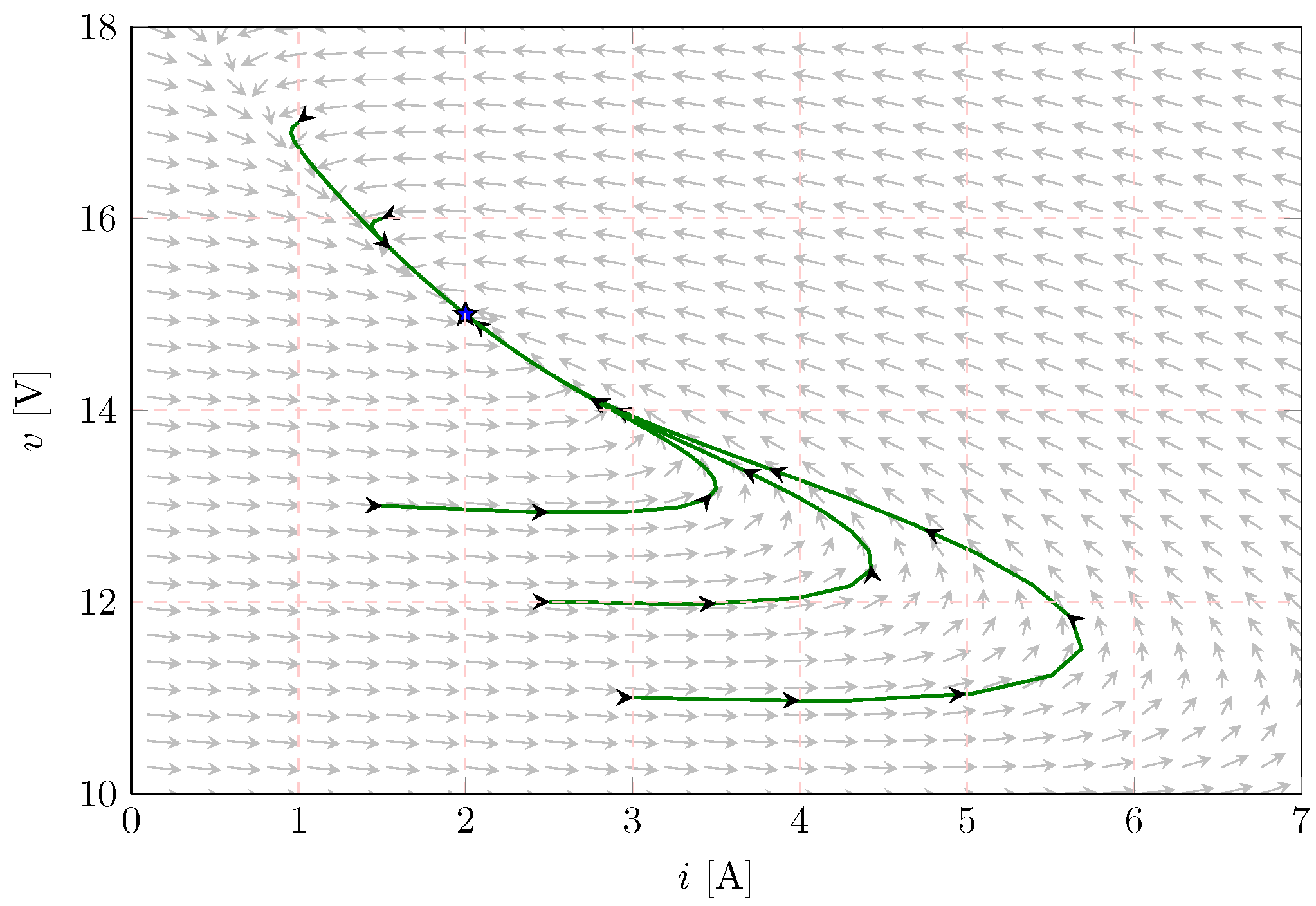
) for the boost converter is calculated with E = 10 V, P = 20 W, x 1 = 2 A, and x 2 = 15 V. Figure 4 also shows five trajectories for different initial points. It can be observed that the state variables move in ranges 1.5 A x 1 ( 0 ) 4 A and 6.5 V x 2 ( 0 ) 17 V . According to the figure, if x 2 ( 0 ) < x 2 , x 1 initially increases above its equilibrium point, while x 2 ( 0 ) goes near the desired equilibrium point; meanwhile, if x 2 ( 0 ) > x 2 , x 1 and x 2 converge directly to their equilibrium points.
Figure 5 illustrates the estimation of the input voltage when the CPL has a constant value ( P = 20 W). Figure 5a presents the dynamic response of the estimate E ^ (blue line) when the input voltage (yellow line) increases from 10 to 8 V. In contrast, Figure 5b reveals the estimate E ^ (blue line) when the input voltage (yellow line) decreases from 10 to 12 V. These figures show that the estimation of the input voltage E ^ can be validated and that its convergence rate is very fast.
Figure 6 depicts the experimental response of the boost converter while considering that the CPL varies between 20 and 40 W like a 100 Hz square waveform. In this case, it is also considered that the desired output voltage is x 2 = 15 V, and the input voltage for the boost converter varies from 10 and 8 V at the same time. Figure 6a shows the output voltage x 2 (yellow line), the inductor current x 1 (green line), the control signal u (blue line), and the estimate P ^ (purple line). Figure 6b depicts the input voltage E (yellow line) and the estimate E ^ (blue line).
In Figure 6a, it can be observed that the adaptive sensorless PI+PBC control can instantly stabilize the output voltage of the boost converter. The settling time for the output voltage is 1.53 ms, and its average overshoot is 5.1 %, while the inductor current has a settling time of around 0.171 ms and no overshoot. This demonstrates the adequate performance of the proposed controller under simultaneous CPL and input voltage variations. Additionally, it is observed that the inductor current x 1 (green line in Figure 7a) increases when the input voltage E decreases. This behavior is expected, given that the balance point for the inductor current depends inversely on the input voltage, as presented in (5) (hyperbolic relation between voltage and current in the presence of a CPL).
Figure 7 presents the experimental response of the boost converter when its input voltage changes from 10 V to 12 V, and the CPL varies between 20 and 40 W like a 100 Hz square waveform simultaneously. The desired output voltage remains the same x 2 = 15 V. Figure 7a illustrates the output voltage x 2 (yellow line), the inductor current x 1 (green line), the control signal u (blue line), and the estimate P ^ (purple line). Figure 7b shows the input voltage E (yellow line) and its estimation E ^ (blue line).
It can be seen in Figure 7a that the adaptive sensorless PI+PBC control instantly continues to regulate the output voltage of the boost converter under the changes considered. This is supported by the fact that the settling time for the proposed controller is 1.53 ms, and its average overshoot is 5.1 %. It is worth mentioning that, as expected, when the voltage input increases, the total current flowing through the inductor decreases since its movement is required to ensure constant power transference from the source to the load.

General Remarks

From the experimental validation presented for a boost converter feeding an unknown CPL while using the proposed controller, it is possible to observe that:
i.
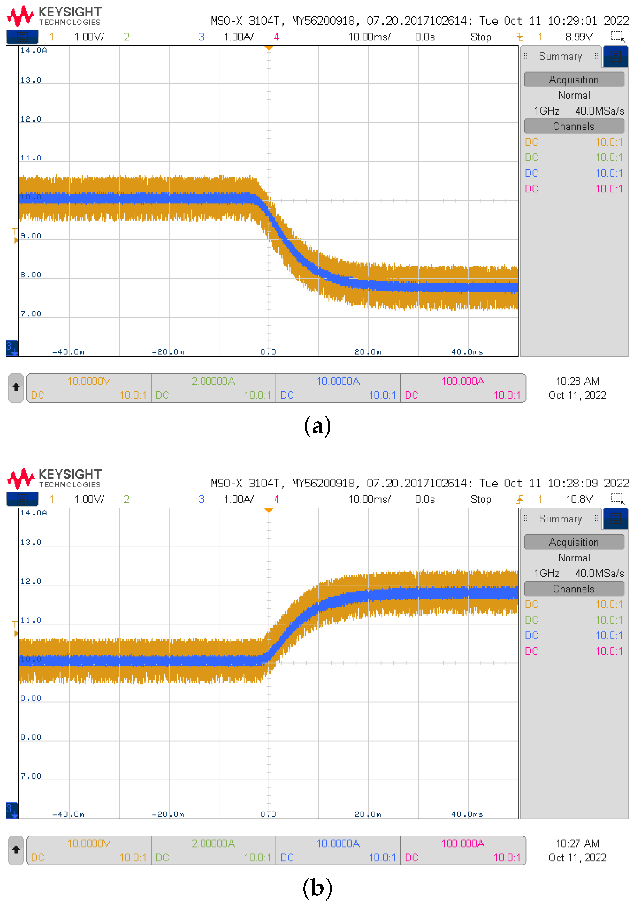
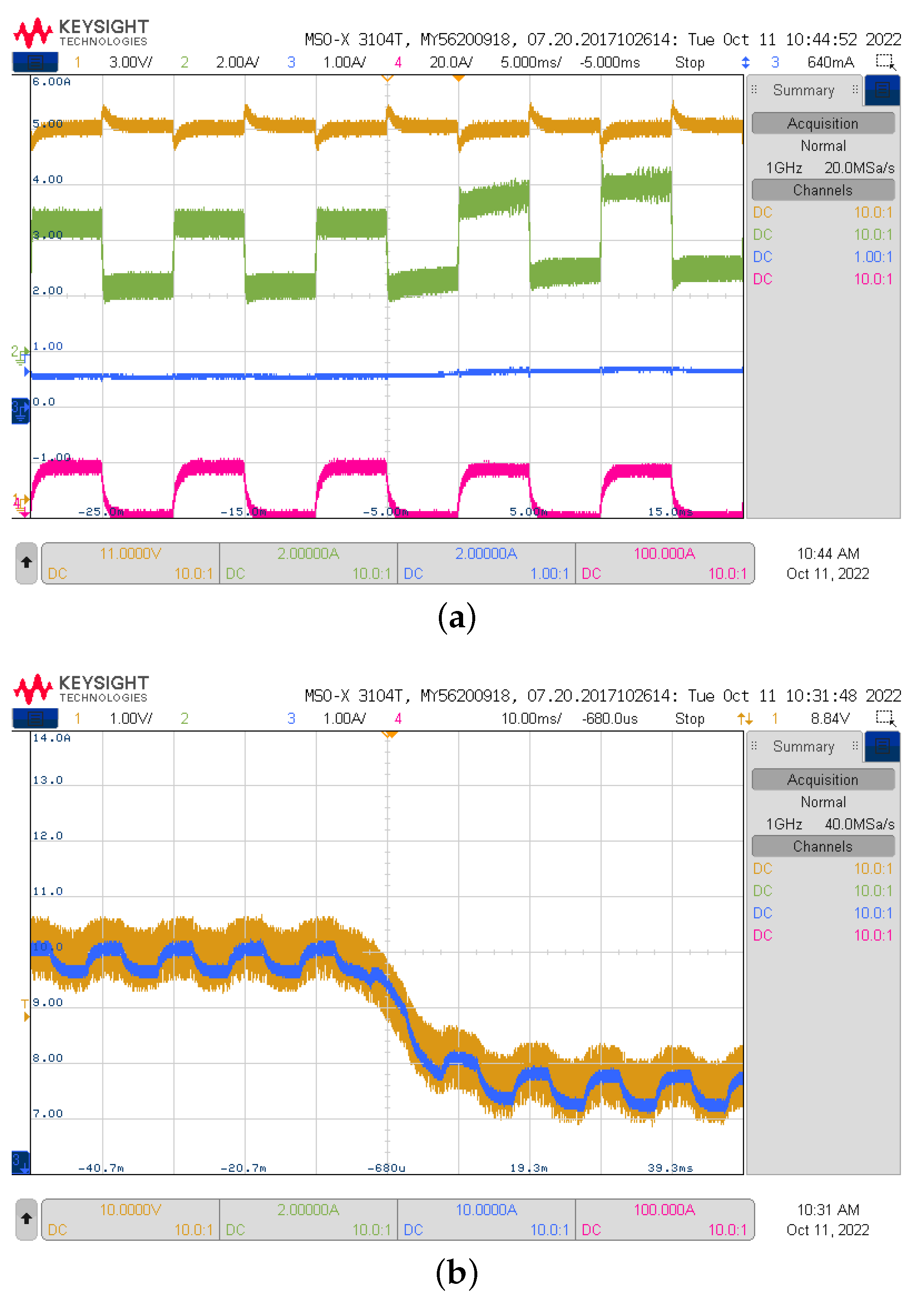
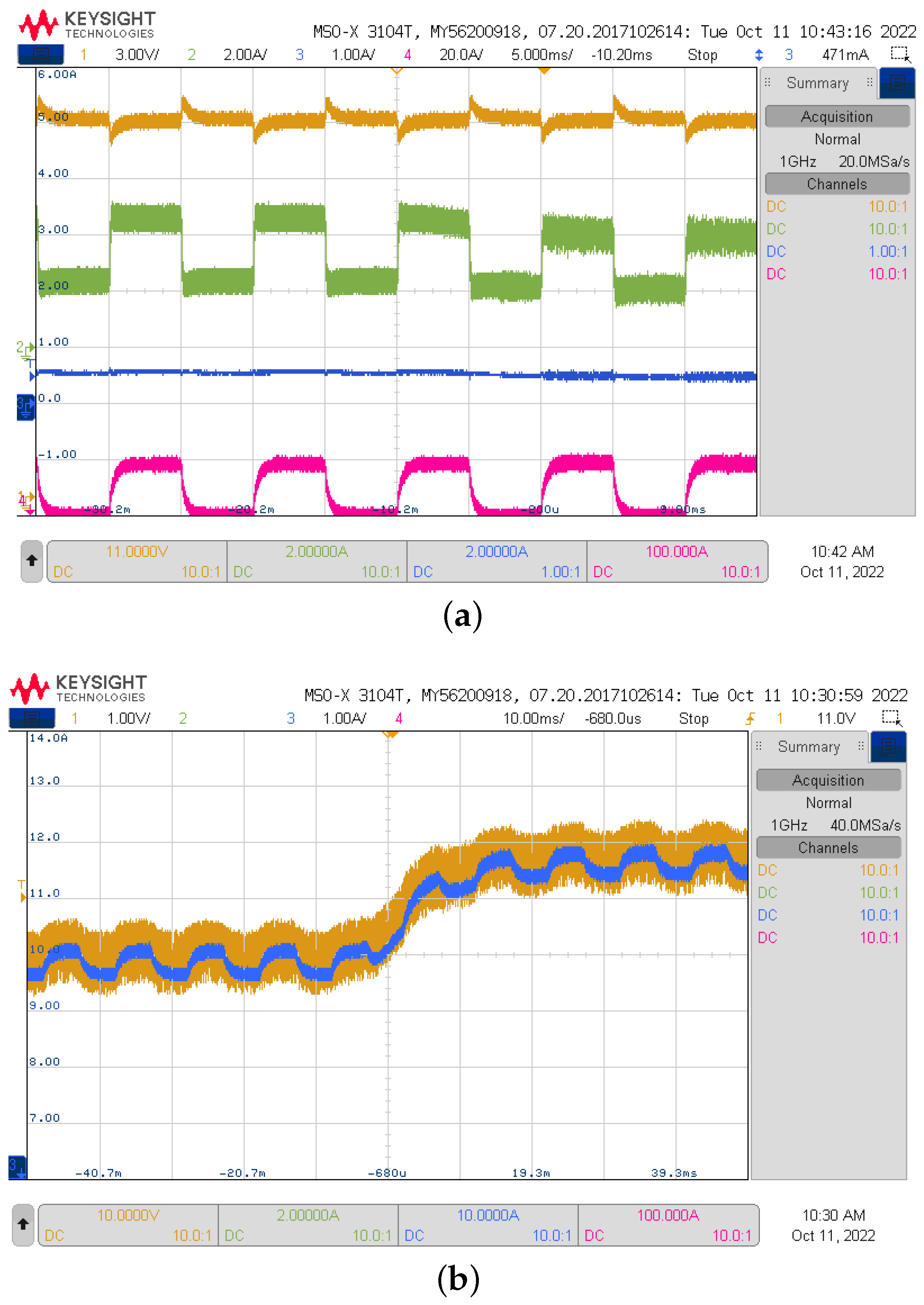
The presented estimator to determine the behavior of the voltage input has an exponential convergence to the exact value when the behavior of the constant power load remains constant (see Figure 5), regardless of whether the voltage input increases or decreases from an initial value. Notwithstanding, when the load varies with a square form and the voltage input also increases or decreases, the behavior of the voltage input estimator follows the average behavior of the input, albeit with square-form oscillations (see Figure 6b and Figure 7b), which is expected because the DO estimator presented in Section 3.3 is dependent on the current measured at the inductor, which is also a function of the current provided to the load.
ii.
The load estimator presented in Figure 6a and Figure 7a converges exponentially to the exact value, as predicted by the I&I method presented in Section 3.2. This is also expected since the estimator depends only on the voltage measured at terminals of the load, which is the control variable that remains constant, with small variations each time the load changes.
iii.
In general, the proposed PI+PBC approach demonstrated easy tuning characteristics (two control gains), and fast asymptotic convergence to the desired voltage reference, regardless of whether the load current and the voltage input are measured or estimated. These characteristics make the proposed PI+PBC structure a robust control approach that deals with voltage control in the face of unknown CPLs, thus reducing the number of sensors required in the physical implementation layer.

5. Conclusions

This paper presented the design of an adaptive control to regulate the output voltage of a DC–DC boost converter supplying an unknown CPL. The proposed controller used PBC theory to stabilize the output voltage at its desired value, and a PI action was added to accelerate its convergence. The PI action maintained a passive output, essential for PBC theory, and injected the desired damping, thus enhancing disturbance rejection. Additionally, the proposed controller added two observers, which allowed it not to depend on some parameters that, in general, can be difficult to measure. The I&I and DO techniques turned the controller into an adaptive sensorless PI+PBC control, whose robustness and effectiveness were evaluated by employing phase portrait analysis and experimental results. The whole set of these tests showed its ability to regulate and maintain the output voltage of the DC–DC boost converter at its desired values.
Some possible future works derived from this research may include: (i) extending the proposed control design and observers to classical second-order DC–DC converters (buck, buck-boost, and non-inverting buck-boost topologies) feeding CPLs, (ii) implementing inverse optimal control with integral action for controlling DC–DC converters in microgrid applications, Developing a sliding mode control with the I&I and DO techniques makes it more robust and allows the system to have a faster convergence.

Author Contributions

Conceptualization, methodology, software, and writing (review and editing): W.G.-G., O.D.M., S.R., C.R. and J.M. All authors have read and agreed to the published version of the manuscript.

Funding

This work was partially supported by the Chilean Government under projects ANID/FONDECYT/1191028, ANID/FONDECYT/1191680, SERC Chile (Anid/Fondap/15110019), and Millennium Institute on Green Ammonia as Energy Vector MIGA (ANID/Millennium Science Initiative Program/ICN2021 023).

Data Availability Statement

No new data were created or analyzed in this study. Data sharing is not applicable to this article.

Conflicts of Interest

The authors declare no conflict of interest.

References

  1. Mathew, E.C.; Das, A. Integration of renewable energy sources with MVDC network. In Proceedings of the 2020 IEEE International Conference on Power Electronics, Drives and Energy Systems (PEDES), Jaipur, India, 16–19 December 2020. [Google Scholar] [CrossRef]
  2. Bharatee, A.; Ray, P.K.; Subudhi, B.; Ghosh, A. Power Management Strategies in a Hybrid Energy Storage System Integrated AC/DC Microgrid: A Review. Energies 2022, 15, 7176. [Google Scholar] [CrossRef]
  3. Silani, A.; Cucuzzella, M.; Scherpen, J.M.; Yazdanpanah, M.J. Robust output regulation for voltage control in DC networks with time-varying loads. Automatica 2022, 135, 109997. [Google Scholar] [CrossRef]
  4. Iskender, I.; Genc, N. Power Electronic Converters in DC Microgrid. In Power Systems; Springer International Publishing: Berlin/Heidelberg, Germany, 2019; pp. 115–137. [Google Scholar] [CrossRef]
  5. Ramos-Paja, C.A.; Montoya, O.D.; Grisales-Noreña, L.F. Photovoltaic System for Microinverter Applications Based on a Non-Electrolytic-Capacitor Boost Converter and a Sliding-Mode Controller. Electronics 2022, 11, 2923. [Google Scholar] [CrossRef]
  6. Xie, D.; Wang, L.; Zhang, Z.; Wang, S.; Kang, L.; Yao, J. Photovoltaic Energy Storage System Based on Bidirectional LLC Resonant Converter Control Technology. Energies 2022, 15, 6436. [Google Scholar] [CrossRef]
  7. Prieto-Araujo, E.; Bolboceanu, D.B.; Sanchez-Sanchez, E.; Gomis-Bellmunt, O. Design methodology of the primary droop voltage control for DC microgrids. In Proceedings of the 2017 IEEE Second International Conference on DC Microgrids (ICDCM), Nuremburg, Germany, 27–29 June 2017. [Google Scholar] [CrossRef]
  8. Gao, F.; Kang, R.; Cao, J.; Yang, T. Primary and secondary control in DC microgrids: A review. J. Mod. Power Syst. Clean Energy 2018, 7, 227–242. [Google Scholar] [CrossRef] [Green Version]
  9. Moayedi, S.; Davoudi, A. Distributed Tertiary Control of DC Microgrid Clusters. IEEE Trans. Power Electron. 2016, 31, 1717–1733. [Google Scholar] [CrossRef]
  10. Oucheriah, S. Nonlinear control of the boost converter subject to unknown constant power load and parasitics. Int. J. Electron. Lett. 2022, 0, 1–11. [Google Scholar] [CrossRef]
  11. Emadi, A.; Khaligh, A.; Rivetta, C.; Williamson, G. Constant Power Loads and Negative Impedance Instability in Automotive Systems: Definition, Modeling, Stability, and Control of Power Electronic Converters and Motor Drives. IEEE Trans. Veh. Technol. 2006, 55, 1112–1125. [Google Scholar] [CrossRef]
  12. Shi, L.; Lei, W.; Li, Z.; Huang, J.; Cui, Y.; Wang, Y. Bilinear Discrete-Time Modeling and Stability Analysis of the Digitally Controlled Dual Active Bridge Converter. IEEE Trans. Power Electron. 2017, 32, 8787–8799. [Google Scholar] [CrossRef]
  13. Chang, Y.; Zhou, P.; Niu, B.; Wang, H.; Xu, N.; Alassafi, M.O.; Ahmad, A.M. Switched-observer-based adaptive output-feedback control design with unknown gain for pure-feedback switched nonlinear systems via average dwell time. Int. J. Syst. Sci. 2021, 52, 1731–1745. [Google Scholar] [CrossRef]
  14. Zhang, H.; Wang, H.; Niu, B.; Zhang, L.; Ahmad, A.M. Sliding-mode surface-based adaptive actor-critic optimal control for switched nonlinear systems with average dwell time. Inf. Sci. 2021, 580, 756–774. [Google Scholar] [CrossRef]
  15. Chen, Q.X.; Chang, X.H. Resilient filter of nonlinear network systems with dynamic event-triggered mechanism and hybrid cyber attack. Appl. Math. Comput. 2022, 434, 127419. [Google Scholar] [CrossRef]
  16. Hamidi, S.A.; Nasiri, A. Stability analysis of a DC–DC converter for battery energy storage system feeding CPL. In Proceedings of the 2015 IEEE International Telecommunications Energy Conference (INTELEC), Osaka, Japan, 18–22 October 2015; pp. 1–5. [Google Scholar]
  17. Singh, S.; Fulwani, D.; Kumar, V. Robust sliding-mode control of dc/dc boost converter feeding a constant power load. IET Power Electron. 2015, 8, 1230–1237. [Google Scholar] [CrossRef]
  18. Wu, J.; Lu, Y. Adaptive backstepping sliding mode control for boost converter with constant power load. IEEE Access 2019, 7, 50797–50807. [Google Scholar] [CrossRef]
  19. Martinez-Treviño, B.A.; El Aroudi, A.; Vidal-Idiarte, E.; Cid-Pastor, A.; Martinez-Salamero, L. Sliding-mode control of a boost converter under constant power loading conditions. IET Power Electron. 2019, 12, 521–529. [Google Scholar] [CrossRef]
  20. He, W.; Li, S.; Yang, J.; Wang, Z. Incremental passivity based control for DC–DC boost converter with circuit parameter perturbations using nonlinear disturbance observer. In Proceedings of the IECON 2016-42nd Annual Conference of the IEEE Industrial Electronics Society, Florence, Italy, 23–26 October 2016; pp. 1353–1358. [Google Scholar]
  21. He, W.; Li, S.; Yang, J.; Wang, Z. Incremental passivity based control for DC–DC boost converters under time-varying disturbances via a generalized proportional integral observer. J. Power Electron. 2018, 18, 147–159. [Google Scholar]
  22. Farsizadeh, H.; Gheisarnejad, M.; Mosayebi, M.; Rafiei, M.; Khooban, M.H. An intelligent and fast controller for DC/DC converter feeding CPL in a DC microgrid. IEEE Trans. Circuits Syst. II Express Briefs 2019, 67, 1104–1108. [Google Scholar] [CrossRef]
  23. He, W.; Shang, Y. Finite-Time Parameter Observer-Based Sliding Mode Control for a DC/DC Boost Converter with Constant Power Loads. Electronics 2022, 11, 819. [Google Scholar] [CrossRef]
  24. Zhang, X.; He, W.; Zhang, Y. An Adaptive Output Feedback Controller for Boost Converter. Electronics 2022, 11, 905. [Google Scholar] [CrossRef]
  25. Zhang, X.; Martinez-Lopez, M.; He, W.; Shang, Y.; Jiang, C.; Moreno-Valenzuela, J. Sensorless Control for DC–DC Boost Converter via Generalized Parameter Estimation-Based Observer. Appl. Sci. 2021, 11, 7761. [Google Scholar] [CrossRef]
  26. Serra, F.M.; Magaldi, G.L.; Fernandez, L.M.; Larregay, G.O.; CH, D.A. IDA-PBC controller of a DC–DC boost converter for continuous and discontinuous conduction mode. IEEE Lat. Am. Trans. 2018, 16, 52–58. [Google Scholar] [CrossRef]
  27. Gil-González, W.; Montoya, O.D.; Espinosa-Perez, G. Adaptive control for second-order DC–DC converters: PBC approach. In Modeling, Operation, and Analysis of DC Grids; Elsevier: Amsterdam, The Netherlands, 2021; pp. 289–310. [Google Scholar]
  28. AL-Nussairi, M.K.; Bayindir, R.; Padmanaban, S.; Mihet-Popa, L.; Siano, P. Constant Power Loads (CPL) with Microgrids: Problem Definition, Stability Analysis and Compensation Techniques. Energies 2017, 10, 1656. [Google Scholar] [CrossRef]
  29. Ortega, R.; Perez, J.A.L.; Nicklasson, P.J.; Sira-Ramirez, H.J. Passivity-Based Control of Euler-Lagrange Systems: Mechanical, Electrical and Electromechanical Applications; Springer Science & Business Media: Berlin/Heidelberg, Germany, 2013. [Google Scholar]
  30. Ortega, R.; Van Der Schaft, A.; Castanos, F.; Astolfi, A. Control by interconnection and standard passivity-based control of port-Hamiltonian systems. IEEE Trans. Autom. Control 2008, 53, 2527–2542. [Google Scholar] [CrossRef] [Green Version]
  31. Harandi, M.R.J.; Taghirad, H.D. On the matching equations of kinetic energy shaping in ida-pbc. J. Frankl. Inst. 2021, 358, 8639–8655. [Google Scholar] [CrossRef]
  32. Cisneros, R.; Gao, R.; Ortega, R.; Husain, I. A PI+ passivity-based control of a wind energy conversion system enabled with a solid-state transformer. Int. J. Control 2021, 94, 2453–2463. [Google Scholar] [CrossRef]
  33. Krstic, M.; Kokotovic, P.V.; Kanellakopoulos, I. Nonlinear and Adaptive Control Design; John Wiley & Sons Inc.: Hoboken, NJ, USA, 1995. [Google Scholar]
Figure 1. Some classical converters employed to interface distributed energy resources and loads in DC networks.
Mathematics 10 04321 g001
Figure 2. Scheme of a DC–DC boost converter supplying a CPL.
Mathematics 10 04321 g002
Figure 3. Experimental setup: (a) oscilloscope, (b) DC electronic device in CPL mode, (c) RT-Box with analog and digital breakout boards, (d) current probe power supply, (e) MOSFET driver power supply, (f) DC–DC boost converter, (g) current probes, (h) input voltage power supply, and (i) differential voltage probe.
Mathematics 10 04321 g003
Figure 4. Phase portrait for the PI+PBC method implemented in the boost converter.
Mathematics 10 04321 g004
Figure 5. Dynamic response of the estimate E ^ : (a) input voltage changes between 10 to 8 V; and (b) input voltage changes between 10 to 12 V. CH1: (1 V/div), CH3: (1 V/div).
Mathematics 10 04321 g005
Figure 6. Dynamic response of the proposed controller: (a) Experimental results for the boost converter when the CPL is a 100 Hz square waveform between 20 and 40 W, with a duty cycle of 0.5 . CH1: x 2 (3 V/div), CH2: x 1 (2 A/div), CH3: u (1/div), CH4: P ^ (20 W/div), and time base of 5 ms. (b) Input voltage changes from 10 V to 8 V. CH1: (1 V/div), CH2: (1 V/div), and time base of 10 ms.
Mathematics 10 04321 g006
Figure 7. Dynamic response of the estimate E ^ : (a) input voltage changes from 10 to 8 V. CH1: x 2 (3 V/div), CH2: x 1 (2 A/div), CH3: u (1/div), CH4: P ^ (20 W/div), and time base of 5 ms; (b) input voltage changes from 10 to 12 V. CH1: (1 V/div), CH2: (1 V/div), and time base of 10 ms.
Mathematics 10 04321 g007
Table 1. Description of the boost converter’s components.
ComponentDescriptionType/Value
Q 1 Power MOSFETIRFB4110
D 1 Schottky Power DiodeRURG8060
LInductorWurth Elektronik 74435584700, 47  μ H
CMultilayer Ceramic CapacitorTDK C5750X7S2A106M230KB, 10 × 10 μ F
Publisher’s Note: MDPI stays neutral with regard to jurisdictional claims in published maps and institutional affiliations.

