Abstract
In this study, the desired tracking control of the upper-limb exoskeleton robot system under model uncertainty and external disturbance is investigated. For this reason, an adaptive neural network using a backstepping control strategy is designed. The difference between the actual values of the upper-limb exoskeleton robot system and the desired values is considered as the tracking error. Afterward, the auxiliary variable based on the tracking error is defined and the virtual control input is obtained. Then, by using the backstepping control procedure and Lyapunov stability concept, the convergence of the position tracking error is proved. Moreover, for the compensation of the model uncertainty and the external disturbance that exist in the upper-limb exoskeleton robot system, an adaptive neural-network procedure is adopted. Furthermore, for the estimation of the unknown coefficient related to the parameters of the neural network, the adaptive law is designed. Finally, the simulation results are prepared for demonstration of the effectiveness of the suggested method on the upper-limb exoskeleton robot system.
Keywords:
neural network; adaptive law; backstepping control; external disturbance; wheelchair robot; tracker design MSC:
68T07; 68T40; 70E60; 93B52; 93D15; 15-XX; 93D21; 93D09; 93Dxx; 62F35; 93C10
1. Introduction
A wheelchair is usually used by disabled and elderly people due to its significant features, including it being easy to operate and energy efficient on flat roads. However, there exist some difficulties for wheelchair users such as the restricted driving of them on rough roads and the ability to climb stairs [1,2,3,4,5]. Thus, recent technologies have been taken into consideration and expanded on by researchers to boost the efficiency of the wheelchair system [6,7,8]. The exoskeleton system is a technical and an assistive robot which allows disabled people to experience better movement in their daily life [9,10,11,12]. The wheelchair upper-limb exoskeleton robot is one of the popular kinds of exoskeleton, which owns noteworthy features and offers many important applications. The main application of the wheelchair upper-limb exoskeleton is the assistance of the physically weak person, and so, a professional and up-to-date controller should be designed to boost the power assistance of these kinds of robots [10,13,14].
The position of each joint of the wheelchair upper-limb exoskeleton robot system is the chief parameter which needs to be controlled [15]. Then, an efficient control procedure should be designed and implemented with the aim of the position tracking control of the wheelchair upper-limb exoskeleton system [16,17,18]. Due to the existence of the nonlinear dynamics, the model’s uncertainty and the external disturbance in the dynamical model of the wheelchair upper-limb exoskeleton robot system, a Lyapunov-based control technique can be employed in the design of the controller for this system [19,20]. In [21], the tracking control of the exoskeleton robot system is investigated by using a sliding mode control scheme. In addition, at the aim of the optimal performance of this system, a genetic algorithm is used to regulate the control parameters optimally. Although, the rejection of the model’s uncertainty and the external disturbance is not examined in these articles. One of the best control schemes is the backstepping control technique which presents a systematic and recursive design procedure which can break down the complicated nonlinear systems into simple subsystems to realize the stabilization and tracking purposes [22,23]. In any physical system, the unknown dynamics such as model uncertainties, external disturbances, and unmodeled dynamics can always diminish the performance level of the system, and so, the compensator system should be designed to reject the unknown dynamics. In [24], the backstepping sliding mode control using a disturbance observer is offered for the control of the exoskeleton robot system. Additionally, the disturbance observer procedure is used to compensate for the uncertainty and external disturbance that exist in the exoskeleton robot system. In [25], the non-singular fast terminal sliding mode tracker that is based on a disturbance observer is used with the aim of tracking the control of the exoskeleton system. In [26,27], the fractional-order terminal sliding tracker for an exoskeleton robot system is proposed. However, in these studies, the adaptive neural network procedure which has a better performance when it is compared to the disturbance observer is not used for the rejection of the unknown dynamics. Therefore, one of the best methods for the rejection of the unknown dynamics is the adaptive neural network technique for the intelligent learning of unknown dynamics [28,29]. In [30], a backstepping sliding mode control tracker using the adaptive neural network approach is suggested for the exoskeleton robot system. In [31], the sliding mode control tracker via the usage of the adaptive neural network is offered for an exoskeleton robot system.
According to the above-mentioned discussion for the design of the controller for the position tacking control of the wheelchair upper-limb exoskeleton robot system, it can be concluded that this research field is still being discussed in the literature. Thus, in this paper, an adaptive neural network control strategy using backstepping control technique is presented with the aim of the position tracking control of the upper-limb exoskeleton robot system. So, the fundamental contributions of this paper can be summarized as follows:
- (i).
- Presentation of the dynamical model of the upper-limb exoskeleton robot system using a common model of the robot system;
- (ii).
- Using backstepping control strategy based on a virtual control input for the demonstration of the convergence of the position tracking error;
- (iii).
- Proposition of the adaptive neural network for the rejection of the model uncertainty and external disturbance;
- (iv).
- Adoption of the adaptation law for the estimation of the unknown constant parameter existed in the neural network process.
Now, the rest of this paper is organized as follows: In Section 2, the dynamical model of the upper-limb exoskeleton robot system is obtained. Some preliminaries are given in Section 3. The adaptive neural network using the backstepping control procedure is presented in Section 4. The simulation outcomes and some conclusions are provided in Section 5 and Section 6, respectively.
2. Model Description of Wheelchair Upper-Limb Exoskeleton System
Every wheelchair upper-limb exoskeleton robot system possesses a schematic as shown in Figure 1 and also owns two chief parts. The first part is related to upper-limb exoskeleton robot which includes three-degrees-of-freedom from joint 1 to joint 4 which are used for adduction/abduction, internal/external rotation, flexion/extension, and elbow flexion/extension functions, respectively [16].
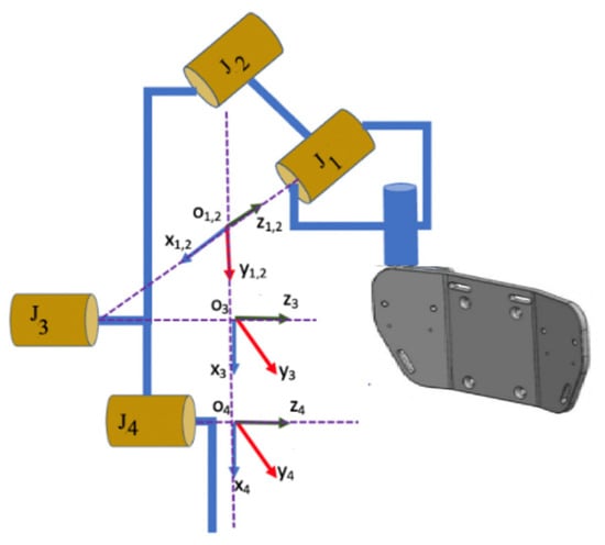
Figure 1.
Review of wheelchair upper-limb exoskeleton robot system.
According to the remark mentioned in [16], for the design of the controller for the wheelchair upper-limb exoskeleton robot system, the free typical dynamical model of the robot system is considered as
where , , and are the position, velocity, and accelerations of the robot system, respectively. The expressions , , and are the inertia, Coriolis and centrifugal forces, and gravitational forces, respectively, which are defined as
with , , and and . Furthermore, the parameter indicates the control input. Moreover, the constants parameters of the upper-limb exoskeleton robot system are considered as Table 1. By doing some mathematical calculations, the dynamical model (1) can be rewritten under the model uncertainty and the external disturbance of as

Table 1.
Parameters of the upper-limb exoskeleton robot system.
3. Preliminaries
In this section, some assumptions and Lemmas are expressed for their usage in the design of the proposed control strategy.
Lemma 1
[32]. For any homogeneous continuous function on , it can be said that if its integration exists and is infinite.
Lemma 2
[33]. For any and , the following inequality realizes
4. Main Results
The main purpose of this part is the design of the adaptive neural-based backstepping control method for the position tracking control of the upper-limb exoskeleton robot system. Hence, the tracking error is defined as
where is the desired position. Now, the supplementary variable is defined as
where and is the virtual control input.
- Step 1: Taking the time-derivative of Equation (8) for results in
With a substitution from (7) into (9) and in consideration of the equation, one can find
whereas , we obtain that
with , it can attain that
Moreover, the virtual control input is designed as
where .
Consider the Lyapunov function . By taking the time-derivative, and a substitution from Equation (12), we have
Using Equation (13), it can gain
- Step 2: Taking the time-derivative of Equation (8) for results in
With a substitution from (7) to (5), one can obtain
Because the terms and are unknown, the adaptive neural network technique is used to estimate them. Hence, the adaptive neural network law is adopted as
where and denote the ideal weight matrices such that are the ideal weight vectors related to the neural network estimate for element of and , respectively. and indicate the corresponding basic function vectors, signifies neural network input and and are the estimation error vectors and their upper boundary are and We define
with
where and are the unknown maximum eigenvalues of matrix and , respectively, which are estimated by adaptive law as
where .
When we consider the Lyapunov function as
With taking time-derivative from above Lyapunov function, we have
With substitution of Equation (15) in the above equation, it can gain
Now, the expression is substituted in above equation which results in
The control input is designed as
With substitution of the control input in (28), we have
From Equations (21) and (22), we can observe that
Based on Lemma 2 , we have
By adding and subtracting of the terms of and , one can find
With consideration of = and =, we can obtain
Now, the adaptation laws (23) and (24) are substituted in above equation and the following result is obtained:
After doing some simplification, we have
Theorem 1.
Consider the upper-limb exoskeleton robot system (5)with uncertainty and external disturbance. Based on the virtual control input (13) and control input (29) and parameter adaptation laws (23) and (24). Then, all of the signals in the closed-loop system are globally bounded, and furthermore, the tracking errors andconverge to zero.
Proof.
Considering the Young’s inequality as , we have
Hence, Equation (36) is converted to
where . By taking integrator from both side of Equation (39), we have
It means that and are bounded and based on the Barbalat Lemma , so, , hence, . Therefore, the position tracking control is realized. □
Remark 1.
As it is obvious, thediscontinuous function results in the chattering phenomenon of the control inputs. Due to this reason, can be replaced by , where is the boundary layer thickness coefficient [34]. Thus, the control inputs can be rewritten as follows:
5. Main Results
In this section, in order to investigate the proficiency of the adaptive neural-network mixed with the backstepping control strategy for desired tracking control of the upper limb exoskeleton robot system in the existence of model uncertainty and external disturbance, the simulation results have been obtained in two different scenarios with different desired values, various model uncertainties, and external disturbances. In each scenario, the simulation results were implemented using various initial conditions. All of the simulation results are modeled in the MATLAB (Simulink environment) software. Additionally, the desired values, control parameter, model uncertainty, external disturbance, and different initial conditions for each scenario are given in Table 2, Table 3, Table 4 and Table 5, respectively.

Table 2.
Desired values.

Table 3.
Design parameters.

Table 4.
Model uncertainty and external disturbance.

Table 5.
Considered initial conditions.
As it can be observed, the simulation results based on the Scenarios 1 and 2 are provided in Figure 2, Figure 3, Figure 4, Figure 5, Figure 6, Figure 7, Figure 8, Figure 9, Figure 10, Figure 11, Figure 12 and Figure 13. The desired tracking of the upper-limb exoskeleton robot system based on Scenario 1 and Scenario 2 is depicted in Figure 2 and Figure 8. As one can observe, the upper limb exoskeleton robot system tracks as desired, completely. The trajectories of the tracking error based on Scenario 1 and Scenario 2 are illustrated in Figure 3 and Figure 9, respectively. From these figures, we can observe the that desired tracking has been performed accurately. Moreover, the sliding surfaces based on Scenario 1 and Scenario 2 are displayed in Figure 4 and Figure 10, respectively, and it is obvious that the sliding surfaces converge to zero eventually. From the figures related to the desired tracking, tracking error, and sliding surface, it can be found that under different initial conditions, the proposed control method is robust and offers an acceptable performance. Additionally, the control inputs, which are obtained based on Scenarios 1 and 2, are shown in Figure 5 and Figure 11, respectively. Lastly, the adaptation laws based on the neural network are displayed in Figure 6, Figure 7, Figure 12 and Figure 13. As one can observe, the approximation of the upper bounds of the model uncertainty and external disturbance are accomplished appropriately. Therefore, from the simulation results, we can observe that the designed method proposes a robust and productive performance under different initial conditions, a diverse model uncertainty and external disturbance, and various desired values.
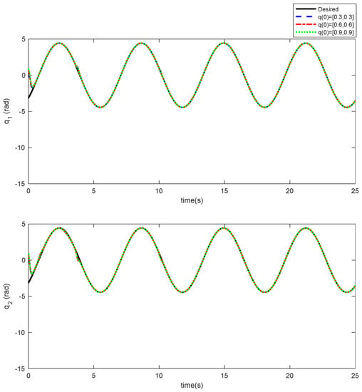
Figure 2.
Desired tracking based on Scenario 1.
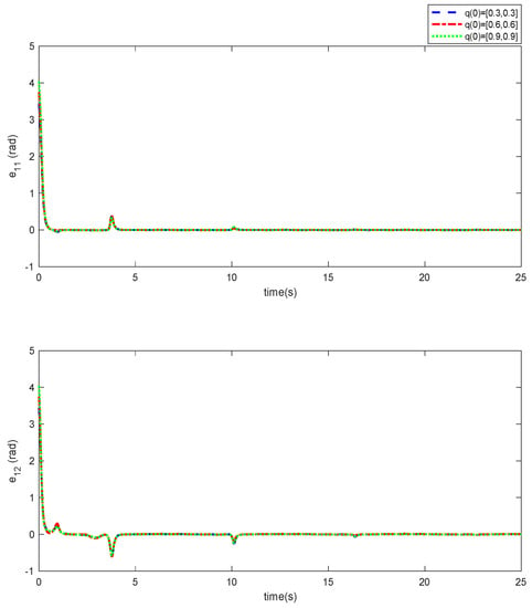
Figure 3.
Trajectory of the tracking error based on Scenario 1.
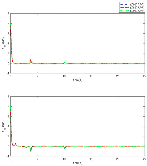
Figure 4.
Sliding surface in Scenario 1.
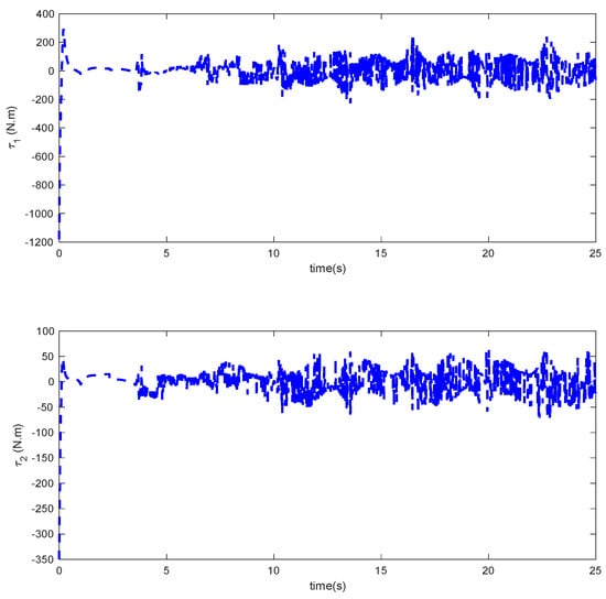
Figure 5.
Control input in Scenario 1.
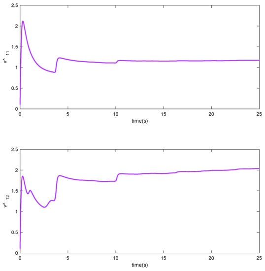
Figure 6.
Adaptation laws , in Scenario 1.
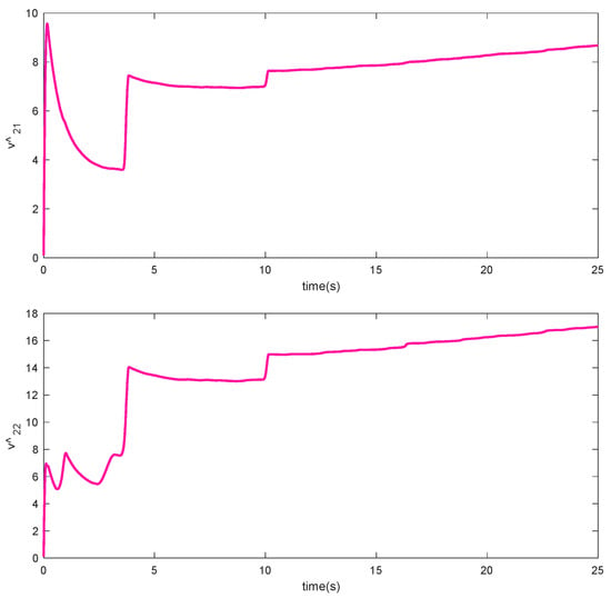
Figure 7.
Adaptation laws , in Scenario 1.
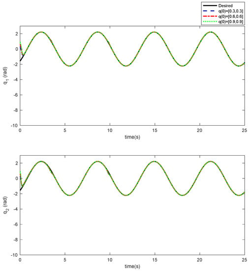
Figure 8.
Desired tracking based on Scenario 2.
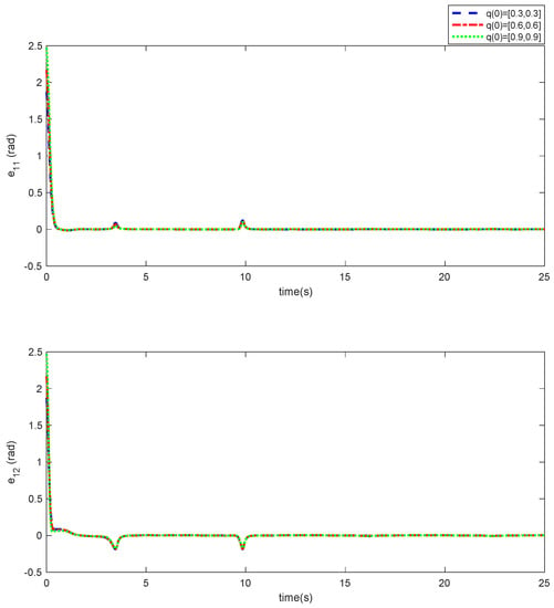
Figure 9.
Trajectory of the tracking error based on Scenario 2.
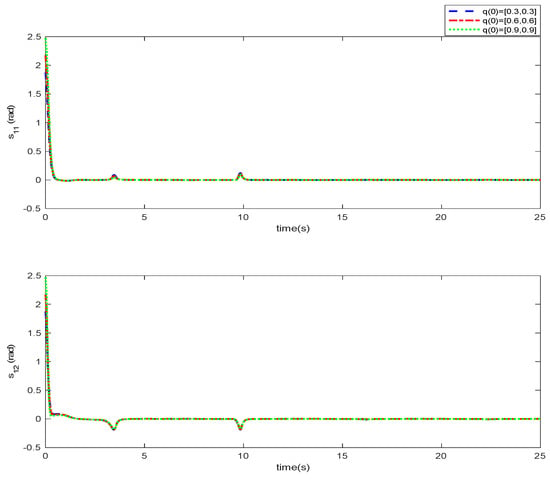
Figure 10.
Sliding surface in Scenario 2.
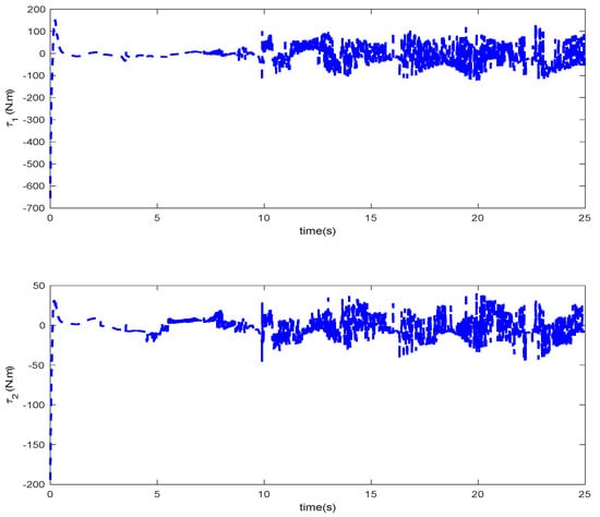
Figure 11.
Control input in Scenario 2.
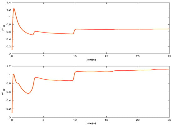
Figure 12.
CAdaptation laws , in Scenario 2.
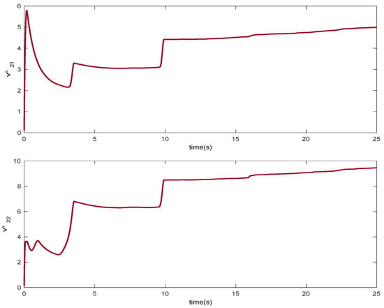
Figure 13.
Adaptation laws , in Scenario 2.
6. Conclusions
In this paper, the position tracking control of the upper-limb exoskeleton robot system in the appearance of the model’s uncertainty and external disturbance has been examined. Due to this reason, one control method based on the adaptive neural network using the backstepping control technique has been developed. Hence, using the backstepping control approach accompanied by the Lyapunov stability theory, the convergence of the position tracking error has been demonstrated. Afterward, the compensation of the model’s uncertainty and external disturbance has been accomplished using the adaptive neural network method. Due to the existence of some uncertainties related to the parameters of the neural network, the adaptation law has been used for the approximation of these uncertainties at any moment. Lastly, the simulation results have been prepared to show that the recommended method is applicable and useful over the upper-limb exoskeleton robot system. Moreover, the development of the adaptive neural network procedure for the upper-limb exoskeleton robot system under the input saturation condition and providing some experimental results are considered to be our future research work.
Author Contributions
Conceptualization, A.A.A., K.-H.H. and F.F.M.E.-S.; formal analysis, S.M., A.A., G.M. and D.-N.L.; funding acquisition, A.A.A.; investigation, S.M., G.M., K.-H.H. and A.A.A.; methodology, F.F.M.E.-S. and S.M.; writing—original draft, G.M., K.-H.H. and A.A.; writing—review and editing, and supervision, S.M., D.-N.L. and A.A.A. All authors have read and agreed to the published version of the manuscript.
Funding
This work is supported by King Salman Center for Disability Research through Research Group no KSRG-2022-021.
Institutional Review Board Statement
Not applicable.
Informed Consent Statement
Not applicable.
Data Availability Statement
The data that support the findings of this study are available within the article.
Acknowledgments
The authors extend their appreciation to the King Salman center For Disability Research for funding this work through Research Group no KSRG-2022-021.
Conflicts of Interest
The authors declare no conflict of interest.
References
- Ikeda, H.; Toyama, T.; Maki, D.; Sato, K.; Nakano, E. Cooperative step-climbing strategy using an autonomous wheelchair and a robot. Robot. Auton. Syst. 2021, 135, 103670. [Google Scholar] [CrossRef]
- Kirby, R.L.; Bennett, S.; Smith, C.; Parker, K.; Thompson, K. Wheelchair curb climbing: Randomized controlled comparison of highly structured and conventional training methods. Arch. Phys. Med. Rehabil. 2008, 89, 2342–2348. [Google Scholar] [CrossRef] [PubMed]
- Calder, C.J.; Kirby, R.L. Fatal wheelchair-related accidents in the United States. Am. J. Phys. Med. Rehabil. 1990, 69, 184–190. [Google Scholar] [CrossRef] [PubMed]
- Long, Y.; Peng, Y. Development and Validation of a Robotic System Combining Mobile Wheelchair and Lower Extremity Exoskeleton. J. Intell. Robot. Syst. 2022, 104, 5. [Google Scholar] [CrossRef]
- Aly, A.A.; Vu, M.T.; El-Sousy, F.F.; Hsia, K.-H.; Alotaibi, A.; Mousa, G.; Le, D.-N.; Mobayen, S. Adaptive Neural Network-Based Fixed-Time Tracking Controller for Disabilities Exoskeleton Wheelchair Robotic System. Mathematics 2022, 10, 3853. [Google Scholar] [CrossRef]
- Escobedo, A.; Spalanzani, A.; Laugier, C. Multimodal control of a robotic wheelchair: Using contextual information for usability improvement. In Proceedings of the 2013 IEEE/RSJ International Conference on Intelligent Robots and Systems, Tokyo, Japan, 3–7 November 2013; pp. 4262–4267. [Google Scholar]
- Aly, A.A.; El-Sousy, F.F.; Alotaibi, A.; Mousa, G.; Le, D.-N.; Mobayen, S. Fuzzy-Based Fixed-Time Nonsingular Tracker of Exoskeleton Robots for Disabilities Using Sliding Mode State Observer. Mathematics 2022, 10, 3147. [Google Scholar] [CrossRef]
- Jafari, M.; Mobayen, S.; Bayat, F.; Roth, H. A nonsingular terminal sliding algorithm for swing and stance control of a prosthetic leg robot. Appl. Math. Model. 2023, 113, 13–29. [Google Scholar] [CrossRef]
- Huang, G.; Ceccarelli, M.; Huang, Q.; Zhang, W.; Yu, Z.; Chen, X.; Mai, J. Design and feasibility study of a leg-exoskeleton assistive wheelchair robot with tests on gluteus medius muscles. Sensors 2019, 19, 548. [Google Scholar] [CrossRef]
- Thøgersen, M.B.; Mohammadi, M.; Gull, M.A.; Bengtson, S.H.; Kobbelgaard, F.V.; Bentsen, B.; Khan, B.Y.A.; Severinsen, K.E.; Bai, S.; Bak, T. User Based Development and Test of the EXOTIC Exoskeleton: Empowering Individuals with Tetraplegia Using a Compact, Versatile, 5-DoF Upper Limb Exoskeleton Controlled through Intelligent Semi-Automated Shared Tongue Control. Sensors 2022, 22, 6919. [Google Scholar] [CrossRef]
- Abdelbar, M.; Mohamed, I.; Abdellatif, A.; Hegaze, M.M. Towards the Mechatronic Development of a New Upper-Limb Exoskeleton (SAMA). Designs 2022, 6, 80. [Google Scholar] [CrossRef]
- Razzaghian, A. A fuzzy neural network-based fractional-order Lyapunov-based robust control strategy for exoskeleton robots: Application in upper-limb rehabilitation. Math. Comput. Simul. 2022, 193, 567–583. [Google Scholar] [CrossRef]
- Gopura, R.; Bandara, D.; Kiguchi, K.; Mann, G.K. Developments in hardware systems of active upper-limb exoskeleton robots: A review. Robot. Auton. Syst. 2016, 75, 203–220. [Google Scholar] [CrossRef]
- Wang, W.; Zhang, J.; Kong, D.; Su, S.; Yuan, X.; Zhao, C. Research on control method of upper limb exoskeleton based on mixed perception model. Robotica 2022, 40, 3669–3685. [Google Scholar] [CrossRef]
- Kapsalyamov, A.; Hussain, S.; Jamwal, P.K. State-of-the-art assistive powered upper limb exoskeletons for elderly. IEEE Access 2020, 8, 178991–179001. [Google Scholar] [CrossRef]
- Teng, L.; Gull, M.A.; Bai, S. PD-based fuzzy sliding mode control of a wheelchair exoskeleton robot. IEEE/ASME Trans. Mechatron. 2020, 25, 2546–2555. [Google Scholar] [CrossRef]
- Gandolla, M.; Dalla Gasperina, S.; Longatelli, V.; Manti, A.; Aquilante, L.; D’Angelo, M.G.; Biffi, E.; Diella, E.; Molteni, F.; Rossini, M. An assistive upper-limb exoskeleton controlled by multi-modal interfaces for severely impaired patients: Development and experimental assessment. Robot. Auton. Syst. 2021, 143, 103822. [Google Scholar] [CrossRef]
- Wu, Q.; Wang, X.; Chen, B.; Wu, H. Development of an RBFN-based neural-fuzzy adaptive control strategy for an upper limb rehabilitation exoskeleton. Mechatronics 2018, 53, 85–94. [Google Scholar] [CrossRef]
- He, W.; Li, Z.; Dong, Y.; Zhao, T. Design and adaptive control for an upper limb robotic exoskeleton in presence of input saturation. IEEE Trans. Neural Netw. Learn. Syst. 2018, 30, 97–108. [Google Scholar] [CrossRef]
- Kang, H.-B.; Wang, J.-H. Adaptive control of 5 DOF upper-limb exoskeleton robot with improved safety. ISA Trans. 2013, 52, 844–852. [Google Scholar] [CrossRef]
- Babaiasl, M.; Goldar, S.N.; Barhaghtalab, M.H.; Meigoli, V. Sliding mode control of an exoskeleton robot for use in upper-limb rehabilitation. In Proceedings of the 2015 3rd RSI International Conference on Robotics and Mechatronics (ICROM), Tehran, Iran, 7–9 October 2015; pp. 694–701. [Google Scholar]
- Zheng, K.; Zhang, Q.; Hu, Y.; Wu, B. Design of fuzzy system-fuzzy neural network-backstepping control for complex robot system. Inf. Sci. 2021, 546, 1230–1255. [Google Scholar] [CrossRef]
- Deng, W.; Yao, J.; Wang, Y.; Yang, X.; Chen, J. Output feedback backstepping control of hydraulic actuators with valve dynamics compensation. Mech. Syst. Signal Process. 2021, 158, 107769. [Google Scholar] [CrossRef]
- Khamar, M.; Edrisi, M. Designing a backstepping sliding mode controller for an assistant human knee exoskeleton based on nonlinear disturbance observer. Mechatronics 2018, 54, 121–132. [Google Scholar] [CrossRef]
- Yang, P.; Ma, X.; Wang, J.; Zhang, G.; Zhang, Y.; Chen, L. Disturbance observer-based terminal sliding mode control of a 5-DOF upper-limb exoskeleton robot. IEEE Access 2019, 7, 62833–62839. [Google Scholar] [CrossRef]
- Ahmed, S.; Wang, H.; Tian, Y. Model-free control using time delay estimation and fractional-order nonsingular fast terminal sliding mode for uncertain lower-limb exoskeleton. J. Vib. Control 2018, 24, 5273–5290. [Google Scholar] [CrossRef]
- Ahmed, S.; Wang, H.; Tian, Y. Robust adaptive fractional-order terminal sliding mode control for lower-limb exoskeleton. Asian J. Control 2019, 21, 473–482. [Google Scholar] [CrossRef]
- Xia, K.; Huo, W. Robust adaptive backstepping neural networks control for spacecraft rendezvous and docking with uncertainties. Nonlinear Dyn. 2016, 84, 1683–1695. [Google Scholar] [CrossRef]
- Sun, L.; He, W.; Sun, C. Adaptive fuzzy relative pose control of spacecraft during rendezvous and proximity maneuvers. IEEE Trans. Fuzzy Syst. 2018, 26, 3440–3451. [Google Scholar] [CrossRef]
- Wu, Q.; Chen, B.; Wu, H. Rbfn-based adaptive backstepping sliding mode control of an upper-limb exoskeleton with dynamic uncertainties. IEEE Access 2019, 7, 134635–134646. [Google Scholar] [CrossRef]
- Chen, X.; Li, D.; Wang, P.; Yang, X.; Li, H. Model-free adaptive sliding mode robust control with neural network estimator for the multi-degree-of-freedom robotic exoskeleton. Complexity 2020, 2020, 1–10. [Google Scholar] [CrossRef]
- Slotine, J.-J.E.; Li, W. Applied Nonlinear Control; Prentice Hall: Englewood Cliffs, NJ, USA, 1991; Volume 199. [Google Scholar]
- Chen, C.; Liu, Z.; Xie, K.; Zhang, Y.; Chen, C.P. Asymptotic adaptive control of nonlinear systems with elimination of overparametrization in a Nussbaum-like design. Automatica 2018, 98, 277–284. [Google Scholar] [CrossRef]
- Afshari, M.; Mobayen, S.; Hajmohammadi, R.; Baleanu, D. Global sliding mode control via linear matrix inequality approach for uncertain chaotic systems with input nonlinearities and multiple delays. J. Comput. Nonlinear Dyn. 2018, 13, 031008. [Google Scholar] [CrossRef]
Publisher’s Note: MDPI stays neutral with regard to jurisdictional claims in published maps and institutional affiliations. |
© 2022 by the authors. Licensee MDPI, Basel, Switzerland. This article is an open access article distributed under the terms and conditions of the Creative Commons Attribution (CC BY) license (https://creativecommons.org/licenses/by/4.0/).