Article

A Combined Control Scheme of Direct Torque Control and Field-Oriented Control Algorithms for Three-Phase Induction Motor: Experimental Validation

1
Wolfson Centre for Magnetics, School of Engineering, Cardiff University, Cardiff CF24 3AA, UK
2
Mechatronics and Laboratory Engineering Department, Sham University, Aleppo 11566, Syria
*
Author to whom correspondence should be addressed.
Mathematics 2022, 10(20), 3842; https://doi.org/10.3390/math10203842
Submission received: 1 September 2022 / Revised: 30 September 2022 / Accepted: 14 October 2022 / Published: 17 October 2022

Abstract

:
In this paper, a combined structure of algorithms based on field-oriented control (FOC) and direct torque control (DTC) is proposed for improving the performance of a three-phase induction motor (IM) over a wide range of torque loads. The objective of this study is to investigate the state-of-the-art research performed on the resilient intersection control management between FOC and DTC algorithms for IM drive. Three algorithms are employed in the proposed scheme: Direct Torque Stator Flux Control (DTSFC), Direct Torque Rotor Flux Control (DTRFC), and the FOC algorithm. The main aim of the control law is to launch the drive system by selecting DTSFC or DTRFC during the transient state while FOC is switched smoothly to the steady-state. The proposed method had several advantages, including the ability to produce torque beyond the pull-out torque range at 340%, high torque dynamics during transient state within 0.5 ms, low chattering up to 0.05 N.m, and fixed frequency at steady-state operation. Furthermore, a comprehensive comparison study has been conducted, including the most recent research, to verify the effectiveness and superiority of the proposed technique. Results were obtained using both MATLAB/Simulink environment and also were experimentally performed by using a dSPACE DS1103 digital signal processing board to verify the concept of the proposed control scheme.

1. Introduction

Induction motors are utilised more frequently in industrial and traction applications due to their robust design, low manufacturing cost, ease of maintenance, and low power-to-weight ratio compared with permanent magnet synchronous motors [1]. In high-performance variable speed drive applications for induction machines, there are two vector control methods: field-oriented control and direct torque control [2,3,4,5,6]. DTC is characterized by a fast dynamic response, structural simplicity, and robustness towards the stochastic and perturbed parameters of the machine [7,8,9]. Moreover, due to the absence of a pulse width modulator, position encoder, and frame transformation, the configuration of DTC is significantly simpler than the FOC [10,11]. In order to improve the performance of an induction motor in both transient and steady states, two methodologies are used in the literature: the first is to develop the algorithm itself, while the second is to use combined algorithms. In terms of the DTC methodology, several recent techniques are dedicated in the literature, such as: Universal Look Up Table (LUT) [12], where Voltage Vectors (VEs) are selected for lower hysteresis boundary conditions of torque and flux with null VEs or under different conditions of the dc-link voltage ratio [13], virtual VEs, where a sequential strategy is integrated with duty ratio optimization algorithm to select the optimal VE that can significantly alleviate the torque ripple [14,15,16], or sector boundary, where the vector plane is divided into sub-sectors with dynamic boundaries, and the rotating vectors are redenoted dynamically [17]. In terms of the FOC algorithm, a full-order, adaptive observer, sensorless speed algorithm with parameter identification is utilised in [18,19,20] to estimate rotational speed. Model Predictive Field-Oriented Control (PFOC), which minimizes the cost function [21], or Adaptive Neuro-Fuzzy Inference-based FOC Systems (ANFIS) [22] are the most attractive recent techniques for the authors to develop the performance of IM. Several approaches are found in the literature related to the second methodology. This technique was first known as the dynamic reconfiguration of algorithms, presented by [23]. Reference [24] provided a synthesis of the DTRFC algorithm by means of sliding mode theory. These control methods only focused on the switching function design for the state variables of rotor flux and torque. However, the combined algorithm DTRFC-FOC has not been fully tested and analysed; the system evolved with much complexity due to the orientation of FOC that was applied for the entire operation. A combined algorithm was proposed by [25] for three-phase induction motor drives. With this proposed control system, a current vector control is connected to a switching table. However, this approach has the drawback of high ripples in torque and flux responses instead of acting variable switching frequency. A new fuzzy logic VC-DTC scheme based on common vector control and direct torque control has been presented in [26]. The system used a current control scheme together with a DTC-type switching table. However, the analysis of torque and flux responses is missing. Furthermore, the system was not tested in the reverse direction. A recent study by [27] achieved a significant reduction in the torque ripple issue of DTC using a fuzzy logic control scheme. However, the system suffers from the low computation of running time. A current control loop in connection with a switching table was conducted by [28]. A brain emotional learning-based intelligent controller (BELBIC) was employed in the system, which provided good performance under different operating conditions. A combined strategy VC-DTC was presented in [29] to use a switching table instead of PI controllers for controlling the stator current. However, high torque and flux ripple could be noticed. To solve this problem, the method in [30] was proposed to employ an artificial neural network instead of the switching table and the hysteresis comparators, which could provide the appropriate logic outputs for the inverter. The design of combined VC–DTC methods was proposed and investigated for two independently controlled induction motors fed by a single Five Leg Inverter (FLI) [31]. However, the difficulty of manually tuning six PI controllers evolved rather than the shared leg of the inverter for two motors, which is the main drawback of this technique. The reconfigurable vector control system is introduced and analyzed with the treatment of the reconfiguration problems in [32]. It motivated the need for reconfiguration of the AC motor control. Reconfiguration is used to improve the working conditions imposed by speed, torque, or other variables. Reconfiguration is also used to maintain the fail-safe operation of the drive [33]. Recently, a new, combined Ant Colony Optimization algorithm (ACO) for the DTC strategy has been studied for optimizing the gains of the PID controller by using a cost function such as Integral Square Error (ISE) [34]. In Reference [35], two different optimization techniques, called Genetic Algorithm (GA) and Particle Swarm Optimization (PSO), were employed for the DTC of a three-phase IM. The ITAE fitness function was selected to evaluate the outer loop of the DTC drive. The results revealed a significant improvement in torque ripple reduction and a high dynamic of DTC.
Following a review of the published studies in this field, it is clear that there are still shortcomings in the absence of an integrated driving system for the induction motor. The lack of capability to work over a wide speed range and load torque with high dynamic and steady-state characteristics is still an issue. Such problems include high dynamics, fixed switching frequency, and low chattering in the torque response. In addition, the ability to provide large torque exceeds the nominal torque value. The contribution of this article is the proposal of a combined FOC and DTC algorithm for an induction motor to effectively enhance the performance over a wide range of torque loads. Its objective is to overcome the issue of torque ripples and variable switching frequency by the full use of both algorithms. In contrast to the models that are listed in the literature review, the proposed new method uses three algorithms: DTSFC, DTRFC, and FOC, to improve the torque response in terms of transient condition, steady state condition, high dynamics, low ripples, and constant frequency of operation. Accordingly, the proposed method enables the motor to produce any torque beyond the breakdown torque within the inverter’s dc-link voltage capabilities. The approach was validated in experiments using an interface device called dSPACE DS1103.
This manuscript is organized as follows: Section 2 presents a detailed assessment of the DTSFC algorithm. Then, an adequate comparison between DTSFC and DTRFC in terms of pull-out torque is performed in Section 3. FOC is described in Section 4. The proposed combined algorithms based on the derivation of the selected algorithms, DTC, FOC, DTSFC, and DTRFC, is given in Section 5. Section 6 presents and discusses the obtained results using MATLAB/Simulink, which is then extended to the experimental validation in Section 7. A comprehensive comparison is provided in Section 8 to verify the feasibility and effectiveness of the proposed algorithm. Section 9 highlights the conclusions and future research from this study.

2. Theoretical Background of the DTC Algorithm

The conventional DTSFC algorithm block diagram is shown in Figure 1. The stator flux amplitude ( Φ s ) and the electromagnetic torque ( T e m ) are controlled using two independent hysteresis controllers (HCs). Each of Φ s and ( T e m ) are estimated based on both the stator currents measurements and the inverter pulses. The two estimated state variables Φ s and T e m are injected into the driving system as feedback signals to be compared with their reference values [36]. In the voltage source inverter, there are eight switching pulsating signals that can be the candidate to energize the semiconductor device of the inverter, two of them are considered zero VEs, whereas six of them are active VEs with the same magnitude [37]. By selecting the appropriate VEs through a lookup table (LUT), the increase and decrease requirements of both Φ s and T e m can be achieved.
An induction motor can be modelled using stator current vector and rotor flux vector equations, which are referred to as a general reference frame, denoted by the superscript “k”. Mathematically approved equations of the entire model of the system started with the IM model, as shown in (1) [38].
d i s k d t d Φ r k d t = 1 σ τ s L m 2 σ τ r L s L r j ω k L m σ L s L r ( 1 τ r j ω ) L m τ r 1 τ r j ( ω k ω ) · i s k Φ r k + 1 σ L s 0 s k
where V s k is the stator VE; p is the number of pole pairs; L m , L r , and L s are the mutual, rotor, and stator self inductances, respectively; ( σ = 1 L m 2 L S L r ) is the leakage factor; τ s and τ r are the stator and rotor time constants, respectively; ω k is the general reference speed; and ω = P · Ω is the electrical rotor speed ( Ω is the mechanical rotor speed). In the stationary reference frame ( α s β s ) , the component derivatives of Φ s s are given in (2) and (3) [39].
d Φ s s α d t = V s s α R s i s s α
d Φ s s β d t = V s s β R s i s s β
where R s is the phase stator resistance. The two components of the stator VE, in the ( α s β s ) reference frame, are calculated via the sensed dc-link E, and the inverter switching pulses of the inverter C a , C b , C c are defined in (4) and (5) [40].
V s s α = 2 3 E [ C a 1 2 ( C b + C c ) ]
V s s β = 1 2 E [ C b C c ]
The two components of Φ r s , in the ( α s β s ) reference frame, are calculated in (6) and (7) [40].
Φ r s α = L r L m ( Φ s s α σ L s i s s α )
Φ r s β = L r L m ( Φ s s β σ L s i s s β )
The position of Φ s s is calculated (8) [41].
θ Φ s = arctan Φ s s β Φ s s α
The equation that relates the two vectors Φ s and Φ r in the synchronous reference frame can be expressed in (9) [42].
Φ r = L m L s 1 1 + j σ τ r ω r Φ s
ω r = ω s ω
where (10) is the slip frequency, which depends on the load. Equation (9) shows that the relationship between the two vectors, Φ s , Φ r , is a low pass filter with a time constant equals to σ τ r . The angle between the stator flux and the rotor flux vectors is given by (11).
γ = arctan σ τ r ω r
The electromagnetic torque can be expressed as [39].
T e m = p L m σ L s L r Φ s Φ r sin γ
According to (8), the six sectors are created as an orientated movement with 60o between each of them so that the first sector starts at the angle (for instants 30 ) of a width of 60 . The four active vectors to control both the stator flux and the electromagnetic torque in the DTC algorithm are shown in Table 1 [42], where the up arrow indicates an increase in flux or torque, while the down arrow indicates a decrease in flux or torque.
It is worth mentioning that the selection of the value of the hysteresis band is an important issue that affects the response of the flux and torque in the DTC algorithm. In general, when a LUT of four effective vectors are to be applied through a sector, it is preferable to use a zero band of the flux and torque regulator. However, if the switching table is expanded specifically by introducing zero voltage vectors, then a non-zero hysteresis window value is desirable for the hysteresis controller of the flux, torque, or both. The selection of the hysteresis window value depends on several factors, including the sampling time and the chosen reference value of the flux and torque. In general, a hysteresis window with a value of 10% of the reference value is an appropriate value [43,44].

3. DTRFC Versus DTSFC in Terms of Pull-Out Torque

Equation (9) demonstrates that while the stator flux vector modulus is maintained constant, the rotor flux value decreases as the machine load increases. To maintain a constant value of electromagnetic torque, the decrease in rotor flux is caused by the increase in load. Thus, this must be compensated for by increasing the angle ( γ ). This results in the machine not being able to exceed a particular torque, known as the breakdown torque. Alternatively, when the rotor flux vector modulus is maintained as a constant, the value of the stator flux grows as the machine’s load increases. Consequently, the machine can generate any torque permitted by the dc-link voltage level. When high pull-out torque is required, these considerations demonstrate the inherent advantage of controlling the rotor flux vector modulus compared to the stator flux control [24]. Equation (13) reported to obtain the breakdown torque [45].
T e m = p L r ( L m L s ) 2 [ τ r ω r ( 1 + σ τ r ω r ) 2 Φ s 2 ]
Equation (13) shows that the electromagnetic torque in the induction motor is dependent on the slip ( ω r ) when the stator flux modulus is constant. We can also derive (13) with respect to ( ω r ) and nullify the derivative in (14).
T e m ω r = 0
The critical electrical angular speed of electrical quantities in the rotor can be stated in (15).
ω r d = 1 σ τ r
The breakdown torque equation can be found in (16) after substituting (15) into (13).
T e m d = p 2 σ L r ( L m L s ) 2 Φ s 2
By substituting (15) into (11), the value of the critical angle can be written in (17).
γ d = arctan ( σ τ r ω r d ) = arctan ( σ τ r 1 σ τ r ) = arctan ( 1 ) = π 4
The critical value of the rotor flux value can be obtained by replacing the value of the critical angular speed from (15) into (9). The critical value of the rotor flux modulus of the tested induction motor will be calculated in (18).
Φ r d = L m L s 1 1 + ( σ τ r 1 σ τ r ) 2 · Φ s = L m L s 1 2 = 0.6826 W b
According to (18), it can be seen that the minimum allowable value of the rotor flux must not be less than the value 0.6829 Wb for the tested motor in the DTSFC algorithm to be able to provide the required value of the electromagnetic torque.

4. Theoretical Background of the FOC Algorithm

4.1. Working Principle

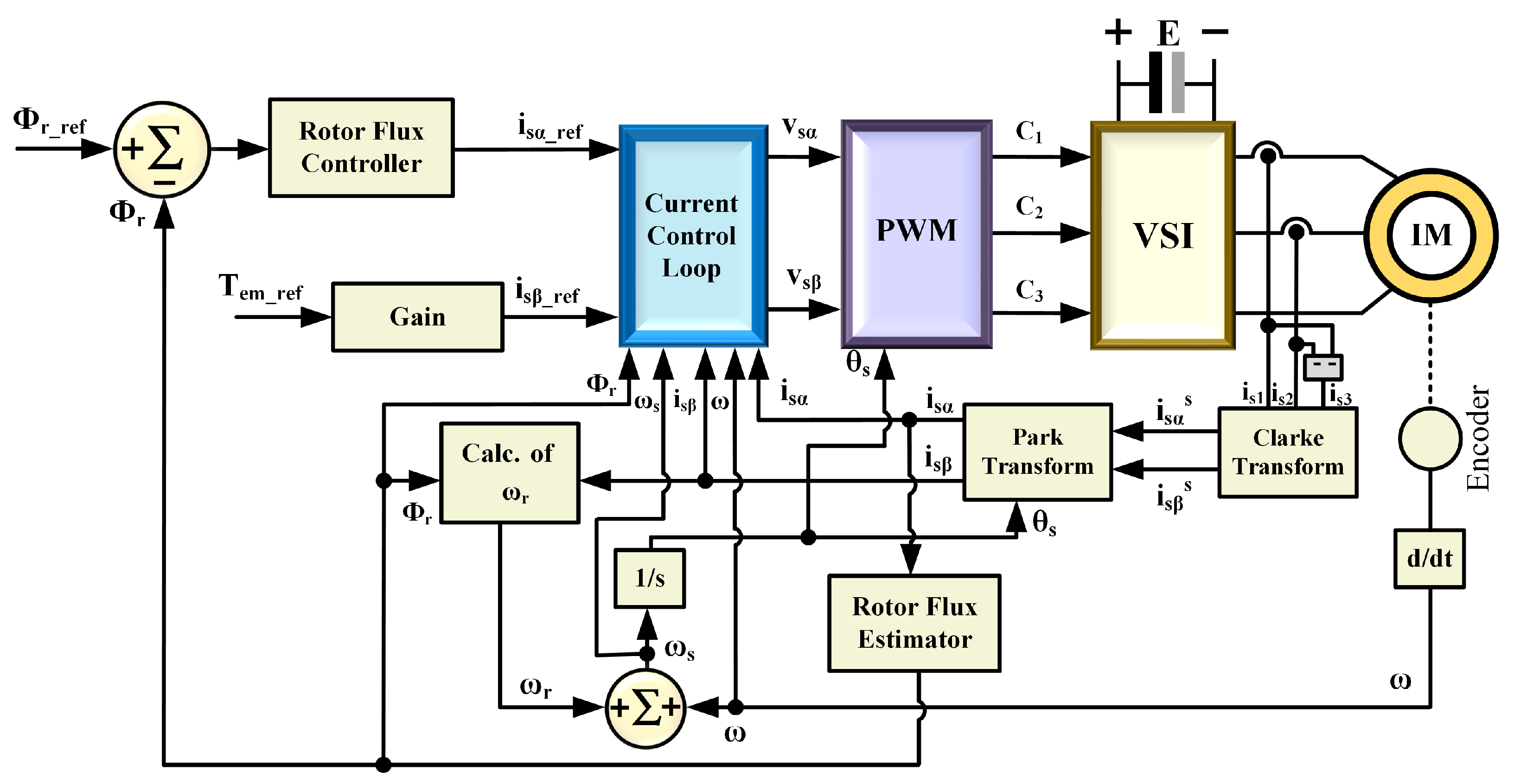
The field orientation concept implies that the direct axis of the rotating reference frame should be pointed towards the rotor flux vector. There are two available rotor field-oriented control schemes, namely IRFOC and DRFOC. In the indirect scheme, IRFOC, no information regarding the rotor flux is needed because it is controlled using the feed-forward method. This advantage offers an easy method for achieving acceptable performance for controlling an induction motor [46]. In the direct approach, DRFOC, it is highly appreciated that the flux is controlled by feedback and an appropriate controller for optimal performance. Consequently, an observer is required to determine the flux vector [47]. The general block diagram of the DRFOC algorithm is illustrated in Figure 2.
It contains two control loops, the first is to control the rotor flux towards the α -coordinate axis, while the second loop is to control the torque according to the β -coordinate axis. The output of the flux regulator and the torque gain are required reference values for each component of the stator current vector ( i s α r e f , i s β r e f ), respectively. In the synchronous reference frame ( α , β ), these values are entered into two intermediate loops to be compared with the measured ones in order to control the currents in the synchronous reference frame ( α , β ) [48]. The feedback currents of the stator’s three phases are sensed and transformed into a two-phase ( α s , β s ) stationary reference frame via Clarke transformation. The rotor speed ω is calculated from the sensed position via an incremental encoder. The angle θ s , calculated from the synchronous speed ω s , is used for the following transformation of currents via Park transformation from the stationary reference frame ( α s , β s ) to the synchronous reference frame ( α , β ). The internal current control loops result in the components ( V s α , V s β ) of the VE in the synchronous reference frame that are entered into the PWM stage. In fact, separate control of torque and rotor flux needs to be carried out, which is the key principle of FOC [49]. In the synchronous reference frame ( α , β ), taking into account the orientation of the rotor flux vector toward the ( α a x i s ), i.e., ( Φ r = Φ r α , Φ r β = 0 ). The real rotor flux component can be written as in (19) [50].
Φ r α = a 2 s + a 1 i s α
The slip speed ω r is estimated using one of the Equations (20) or (21) [51].
ω r = a 2 i s β | Φ r |
ω r = a 2 Φ r L r p L m T e m Φ r = a 2 L r p L m Φ r 2 T e m
By substituting (20) into (21), the torque can be written as in (22).
T e m = p L m L r ( Φ r i s β )
The rotor flux angle (the orientation angle) can be calculated by the integration of the synchronous speed ω s , which is the summation of the slip and rotor speeds, as in (23) [52].
ω s = ω r + ω
In relation to the IM mathematical model in (1), (21), and (24), accordingly, the block diagrams of the motor can be facilitated based on the α and β axes, as clarified in Figure 3.
Where ζ α = 1 b ( ω s i s β + a 3 Φ r α ) and ζ β = 1 b ( ω s i s α + a 5 i s β + a 4 ω Φ r α ) are the damping factors according to the α and β axes. Likewise, a 1 , a 2 , a 3 , a 4 , and a 5 are the motor constants that are detailed in Appendix C. For regulation purposes, the proportional-integral regulator PI will be chosen for the two axes ( α , β ). PID controllers are often a favourable choice due to the simplicity in tuning for performance and robustness requirements, as illustrated in Appendix B. The trial and error method is used to find the optimum values for Kp and Ki. Moreover, it can attain a zero steady-state error in the presence of constant disturbances [53]. Nevertheless, this controller suffers from the windup issue due to the presence of the integrator, causing the system to become unstable. This problem requires solving by using one of the anti-windup techniques to maintain the system stability [54].

4.2. Setting Gain Controls of the FOC Algorithm

To calculate the regulators gains, the pole-zero cancellation technique will be used. This technique does not change the order of the system. It is for simplicity’s purpose [55]. Figure 4a,b show the rotor flux controlling according to the α -axis and i s β component based on the β -axis, which means indirectly controlling the electromagnetic torque, as stated by (24). Figure 4a shows the gains of the current regulator in the inner loop for FOC. Subsequently, calculating the gains of the rotor flux regulator can be defined in the outer loop as well. The inner loop transfer function can be written as in (24).
i s α i s α r e f = K P ( α ) I · b s + K P ( α ) I · b
where the following equation was suggested in (25):
a 5 = K I ( α ) I K P ( α ) I K I ( α ) I = a 5 · K P ( α ) I
The gain K P ( α ) I is optional and can be tuned by the designer, the gain K I ( α ) I is calculated from (25). The outer loop transfer function of the rotor flux is as in (26).
Φ r Φ r r e f = K P ( α ) Φ r · K P ( α ) I · b · a 2 S 2 + K P ( α ) I · b · S + K P ( α ) Φ r · K P ( α ) I · b · a 2
where (27) expresses the following:
a 1 = K I ( α ) Φ r K P ( α ) Φ r
The proportional gain K P is for the rotor flux regulator defined in (28), presume that ξ = 1 2 as in (28) [56].
2 ξ ω n = K P ( α ) I . b ω n = K P ( α ) I · b 2 . 1 2 ω n 2 = K P ( α ) Φ r · K P ( α ) I · b · a 2
K P ( α ) Φ r = ω n 2 K P ( α ) I · b · a 2
Recall (27), the integral gain of the rotor flux regulator can be calculated as in (29).
K I ( α ) Φ r = a 1 · K P ( α ) Φ r
According to Figure 4b, the loop transfer function of i s β can be written in (30).
i s β i s β r e f = K P ( β ) I · b S + K P ( β ) I · b
where (31) was deemed as follows:
a 5 = K I ( β ) I K P ( β ) I K I ( β ) I = a 5 . K P ( β ) I
The value of K P ( β ) I is optional and can be tuned by the designer, and then the gain K I ( β ) I is calculated from (30). Appendix B, Table A2 determines the trial and error tuning method was used to obtain the optimal value of the gains for the PI current controller based on the ( α β ) reference frame; Table A2 also shows the substituted value of a5 related to Kp and Ki for the calculation. The a5 constant is illustrated in Appendix C for constant motor equations, which also include a1, a2, a3, a4, and b.

5. The Proposed Combined FOC and DTC Algorithms over a Wide Torque Operation Range

An improved drive system was designed and built to capitalize on the advantages of both the DTC and FOC algorithms while neglecting their drawbacks. The new driving system contains three algorithms, DTSFC, DTRFC, and FOC. The transition from one algorithm to the other depends on a specific control law that guarantees a smooth transition regardless of the operation point. High dynamic performance in the transient state can be achieved using DTSFC or DTRFC algorithms, while high performance in the steady state is achieved using the FOC algorithm. This type of system is called dynamic reconfiguration, as mentioned above.
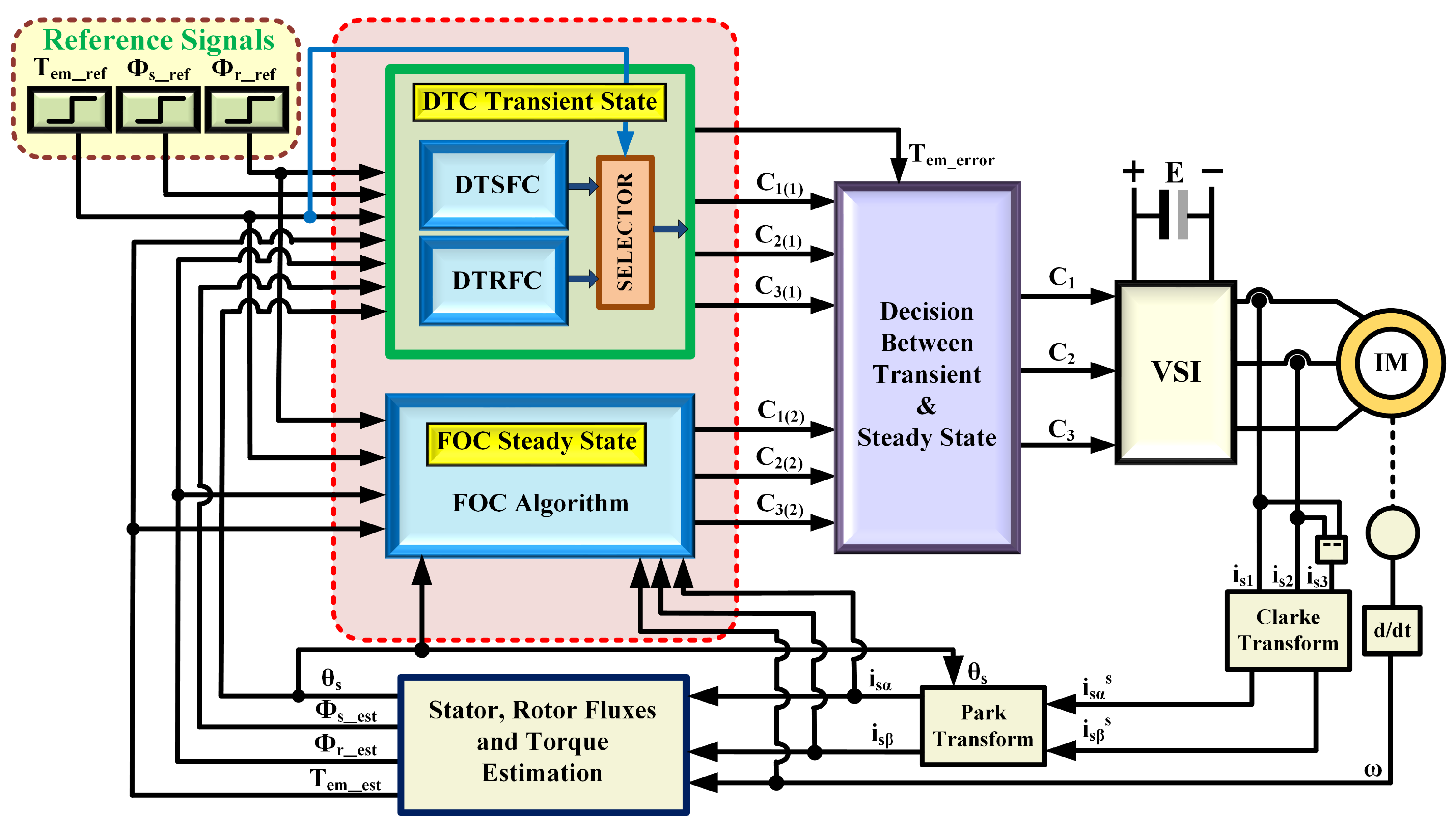
Figure 5 presents the block diagram of the proposed combined FOC-DTC algorithm based on the concepts of direct and indirect driving of the voltage source inverter. The reference values Φ s r e f and T e m r e f are applied to the DTSFC algorithm, while Φ r r e f and T e m r e f are applied to both the DTRFC and FOC algorithms. The selection of DTSFC or DTRFC during the transient state is achieved via a control law based on the torque command, while the transition between the transient state and the steady state (or vice versa) is achieved via a control law based on the torque error. All state variables are estimated within the estimation block after measuring the rotor position and the three-phase currents (measuring two currents and then calculating the third-phase current). The orientation angle θ s is calculated based on (23). The final pulses are applied to semiconductor switches of an inverter that drives the three-phase induction motor.
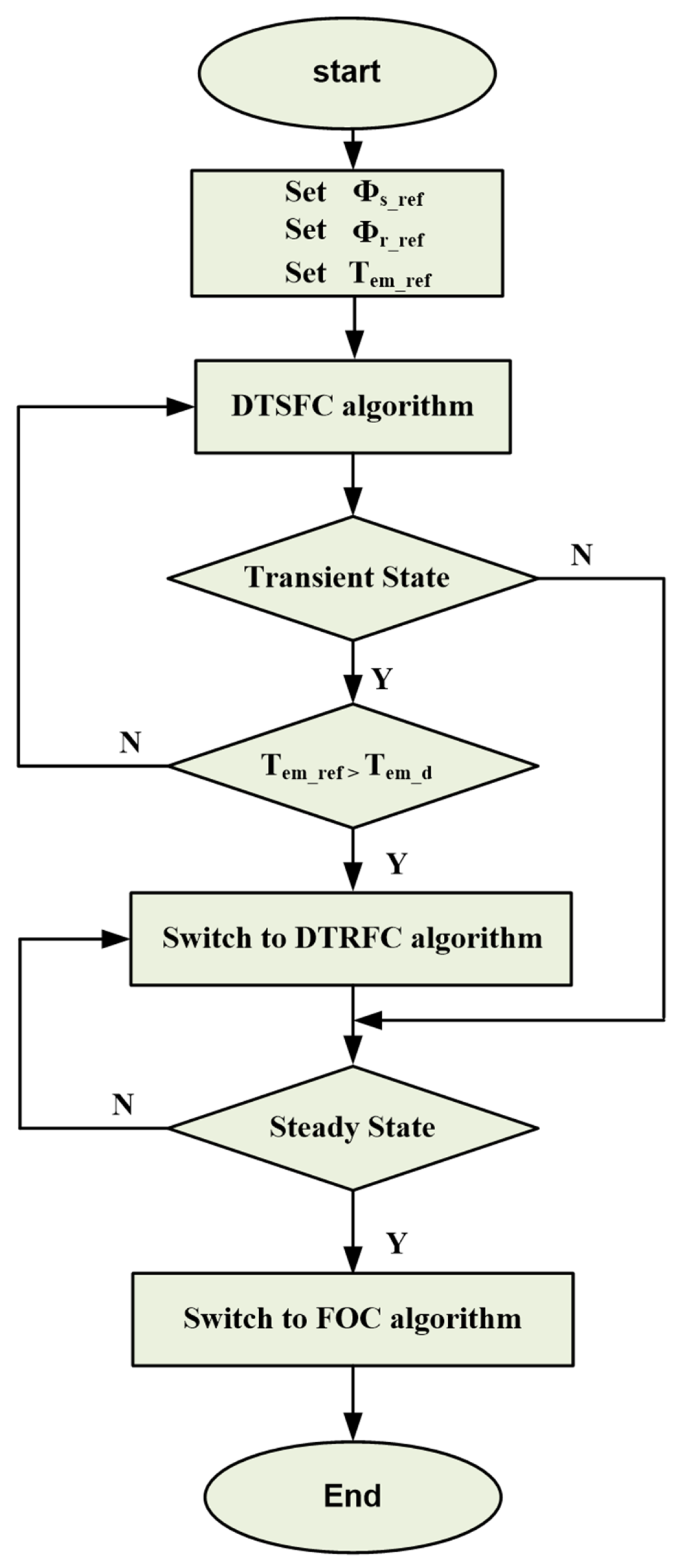
Figure 6 is a flowchart of the transition between the three algorithms. The DTSFC algorithm initially runs at the start of the torque production. This algorithm remains in operation as long as the transient state is satisfied and the reference torque is less than the critical torque T e m d . However, the DTRFC algorithm is selected once the reference torque exceeding the critical value is requested. The two algorithms, DTSFC and DTRFC, guarantee high torque dynamics within the transient state. When the steady state starts, The FOC algorithm is allowed to drive the inverter. The steady state is determined using a control law whose operation is based on the comparison of the torque error T e m e r r o r with a certain threshold ( δ ) specified by the user. If the torque error signal reaches the specified threshold ( δ ) , the proposed control allows the pulses generated by the FOC algorithm to be applied to the inverter while preventing the generated pulses from DTSFC or DTRFC. This is because of the concern about achieving low torque ripples and maintaining constant switched frequency. In fact, choosing the threshold value is an important issue in order to smoothly switch between both algorithms.

6. Simulation Results and Implementation

All aspects of the theoretical study are carefully designed using the MATLAB/Simulink platform. The simulation results were performed on a squirrel cage three-phase induction motor of 50 Hz, 230/400 V, and 0.25 kW. The rated speed is 1350 rpm, and the rated stator and rotor fluxes are 1.14 and 0.945 Wb, which were derived from the equations in Appendix E at rated torque 1.76 N.m, as given in Appendix A.

6.1. Simulation Results of DTRFC Versus DTSFC

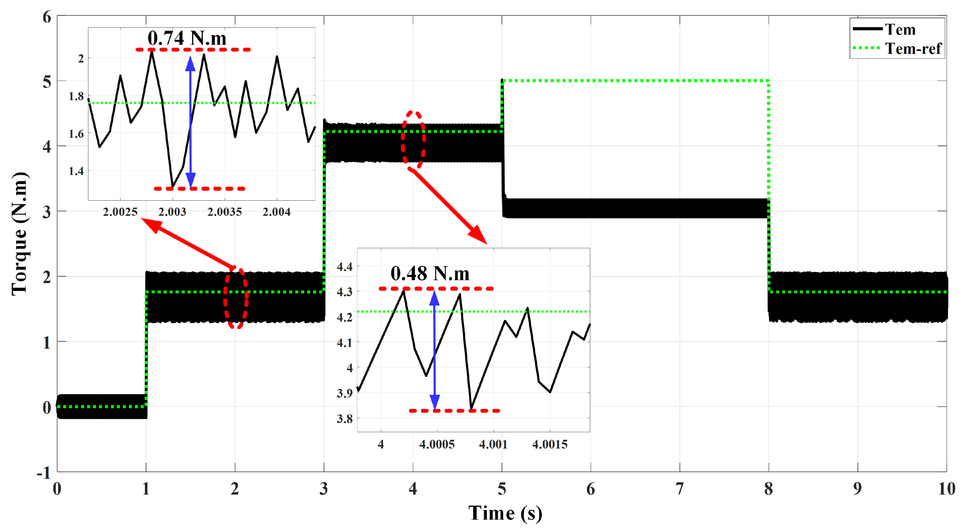
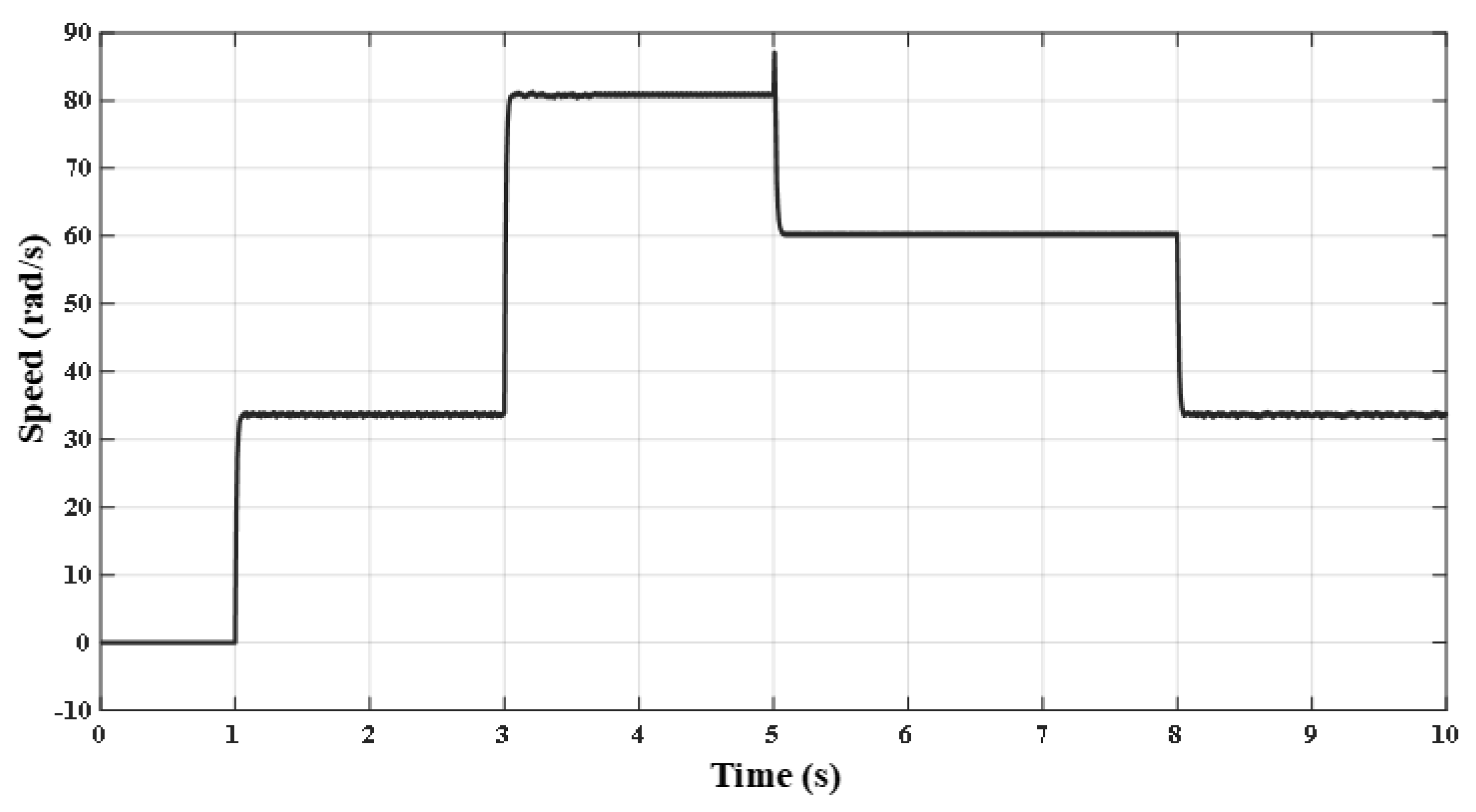
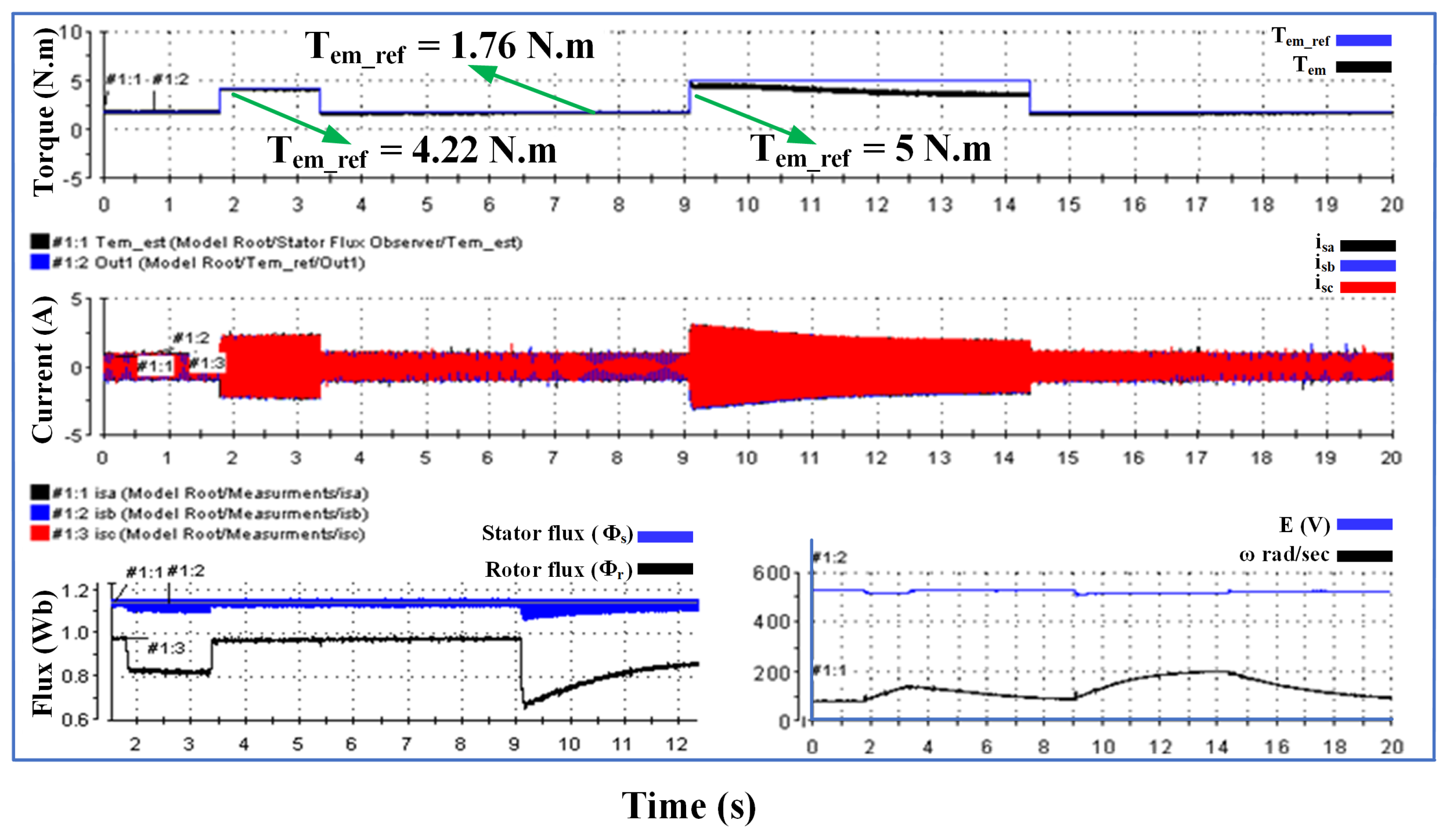
Figure 7 and Figure 8 show the performance of the DTSFC algorithm tested for successive steps at the reference torque. The nominal value of torque of 1.76 N.m was requested at 1 s, while a reference torque value was requested to be equal to the critical value, which is 4.22 N.m at 3 s. Moreover, the reference value of 5 N.m was requested at a 5-s period, exceeding the critical torque value.
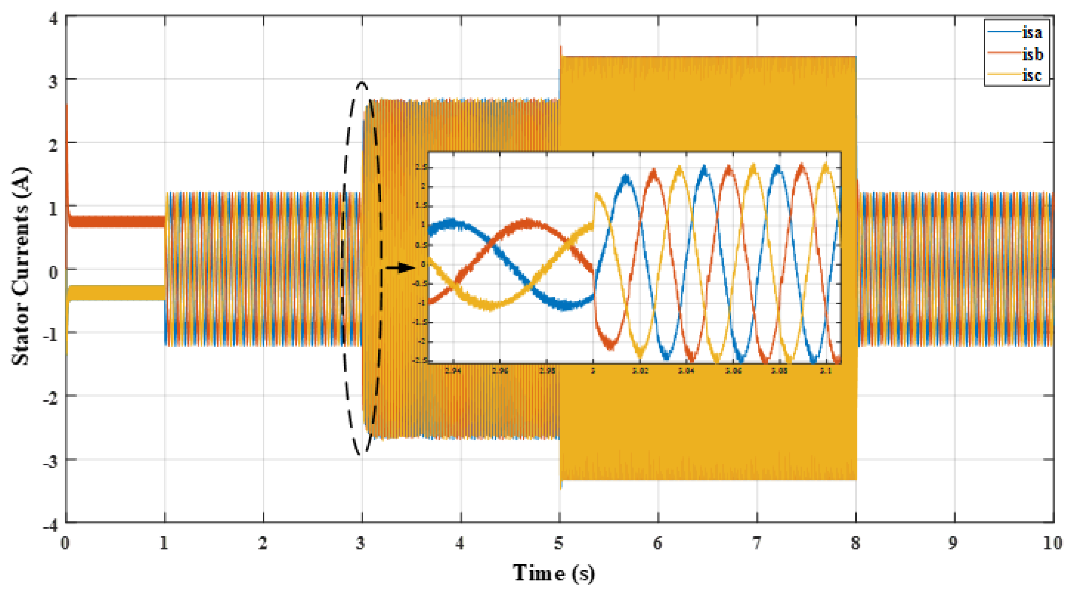
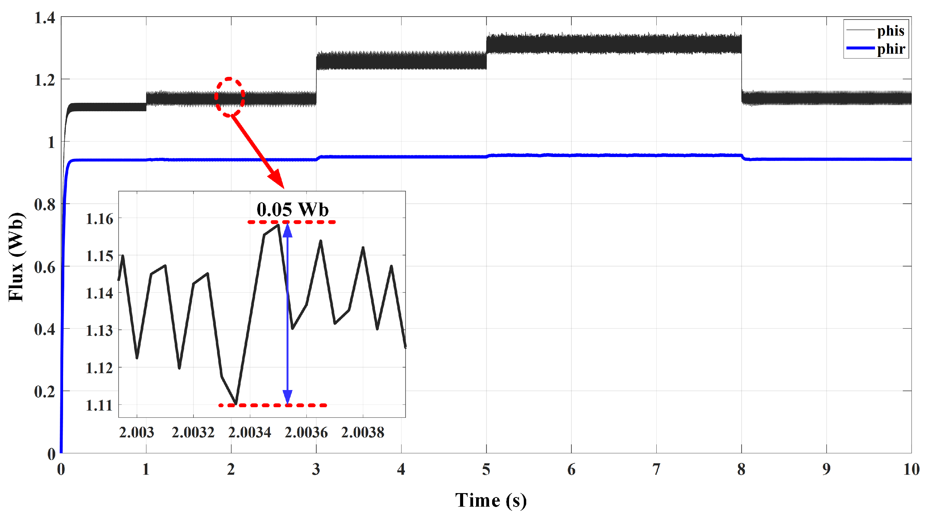
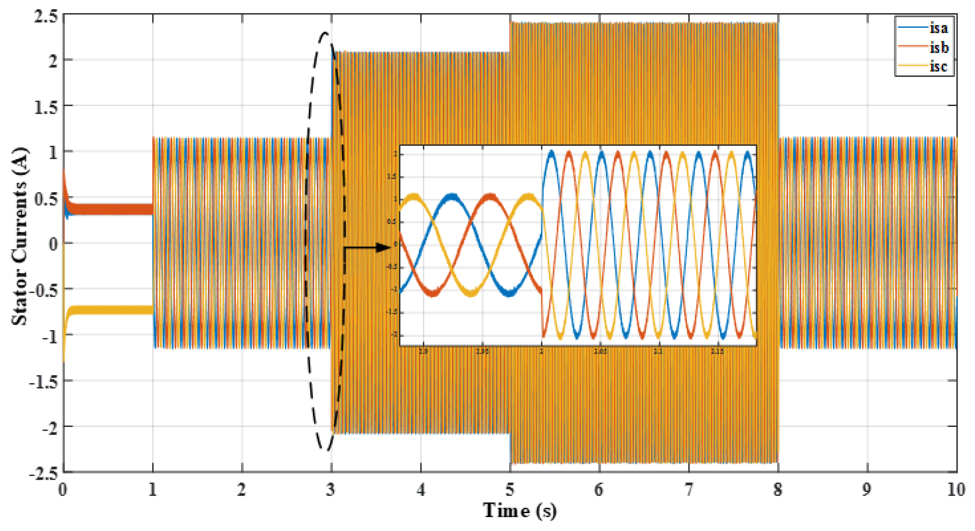
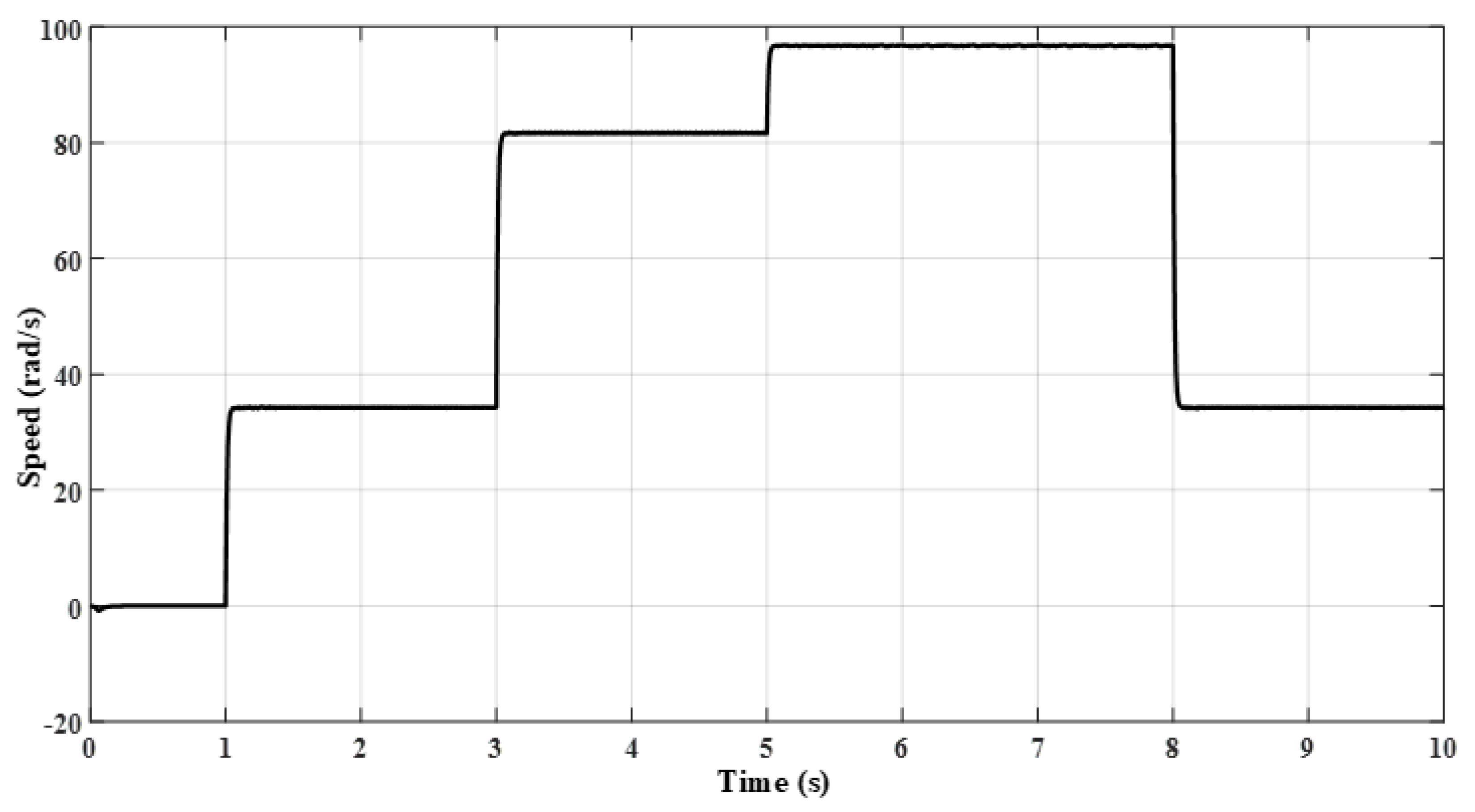
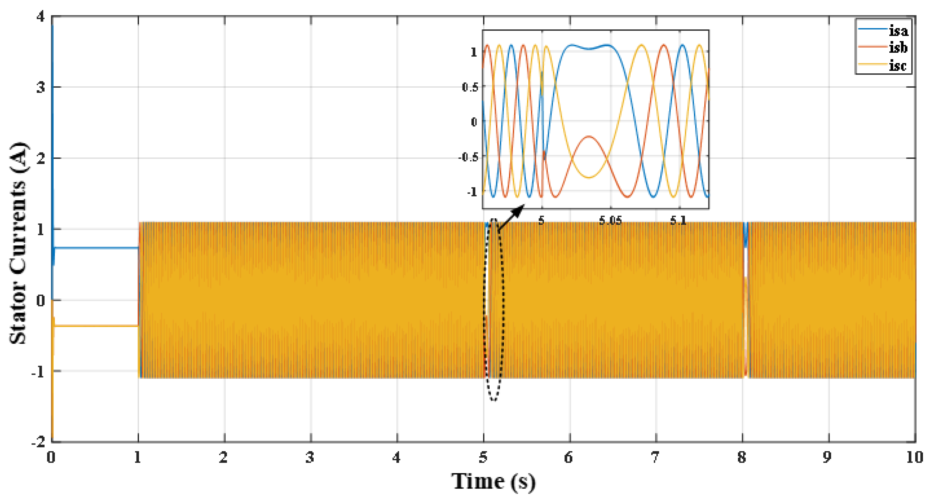
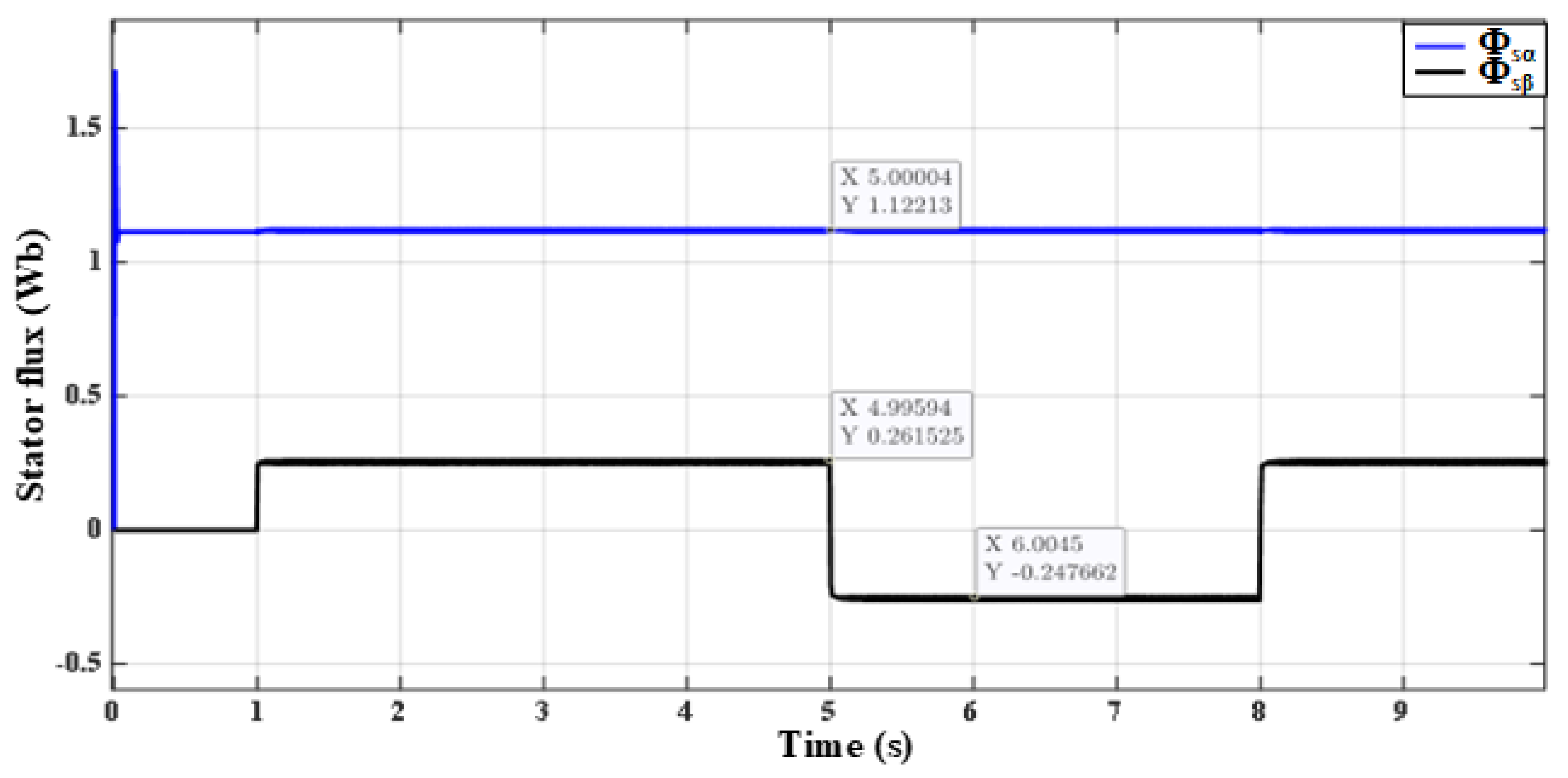
It is illustrated that the performance of DTSFC remained satisfactory as long as the required reference torque did not exceed the critical value. However, DTSFC failed when this value was exceeded. The torque chattering in Figure 8, at the time domain 1 to 3 s, is approximately 0.74 N.m at a speed of 33 rad/s, while the torque oscillation at the time domain 3 to 5 s is approximately 0.48 N.m at a speed of 81 rad/s. This difference is due to the fact that in the second range, the value of the critical torque was requested. Thus, the regulation process is in a critical state before its collapse. In the range 5 to 8 s, the torque was completely out of regulation as a result of requesting a reference torque that was greater than the critical torque. Therefore, low torque oscillation is not considered because the motor is no longer able to work with the required torque. The successive steps of the reference torque were accompanied by a drop in the rotor flux value (the stator flux remained regulated around the reference value of 1.14 Wb, as illustrated in Figure 7. According to (9), the decrease in rotor flux with increasing load is due to the inverse relationship between rotor flux and slip frequency. It can be observed from Figure 7 that the value of the rotor flux decreased at 5 s to 0.396 Wb. This aforementioned value is less than the critical value calculated in (18). Figure 9 and Figure 10 show the three-phase motor currents and the rotor speed of the DTSFC algorithm for the same previous successive steps of the torque. It can be observed that currents increased to 2.625 A per phase, with the increase in the reference torque exceeding their rated values. When the nominal torque was requested again, the value of the currents decreased to a value close to their nominal values. According to the DTRFC algorithm, as illustrated in Figure 11 and Figure 12, the performance tested based on the command of torque load operation was exactly the same as the steps in Figure 8 at the same time intervals. It is demonstrated that the DTRFC algorithm was able to provide the desired value of the torque in accordance with the required reference steps based on the allowance of a dc-link voltage of the inverter. In addition, Figure 11 and Figure 12 showed that the stator flux modulus increased with the increase in the required reference torque while the rotor flux modulus remained regulated around its reference value of 0.945 Wb. The successive increased steps of the reference torque were accompanied by an increase in the value of the three-phase motor currents exceeding their nominal values, as clearly seen in Figure 13 and Figure 14.

6.2. Simulation Results of FOC with Rotor Flux Vector Orientation towards ( α A x i s )

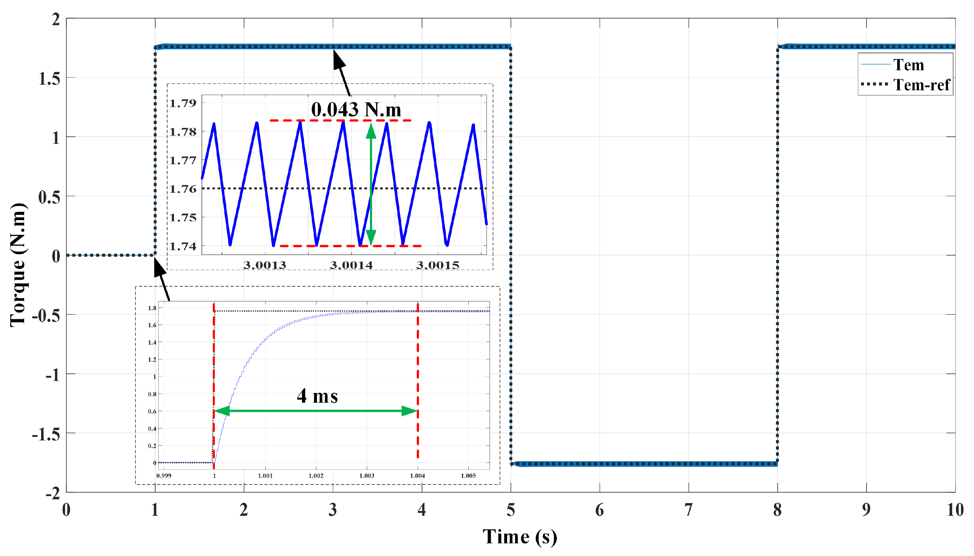
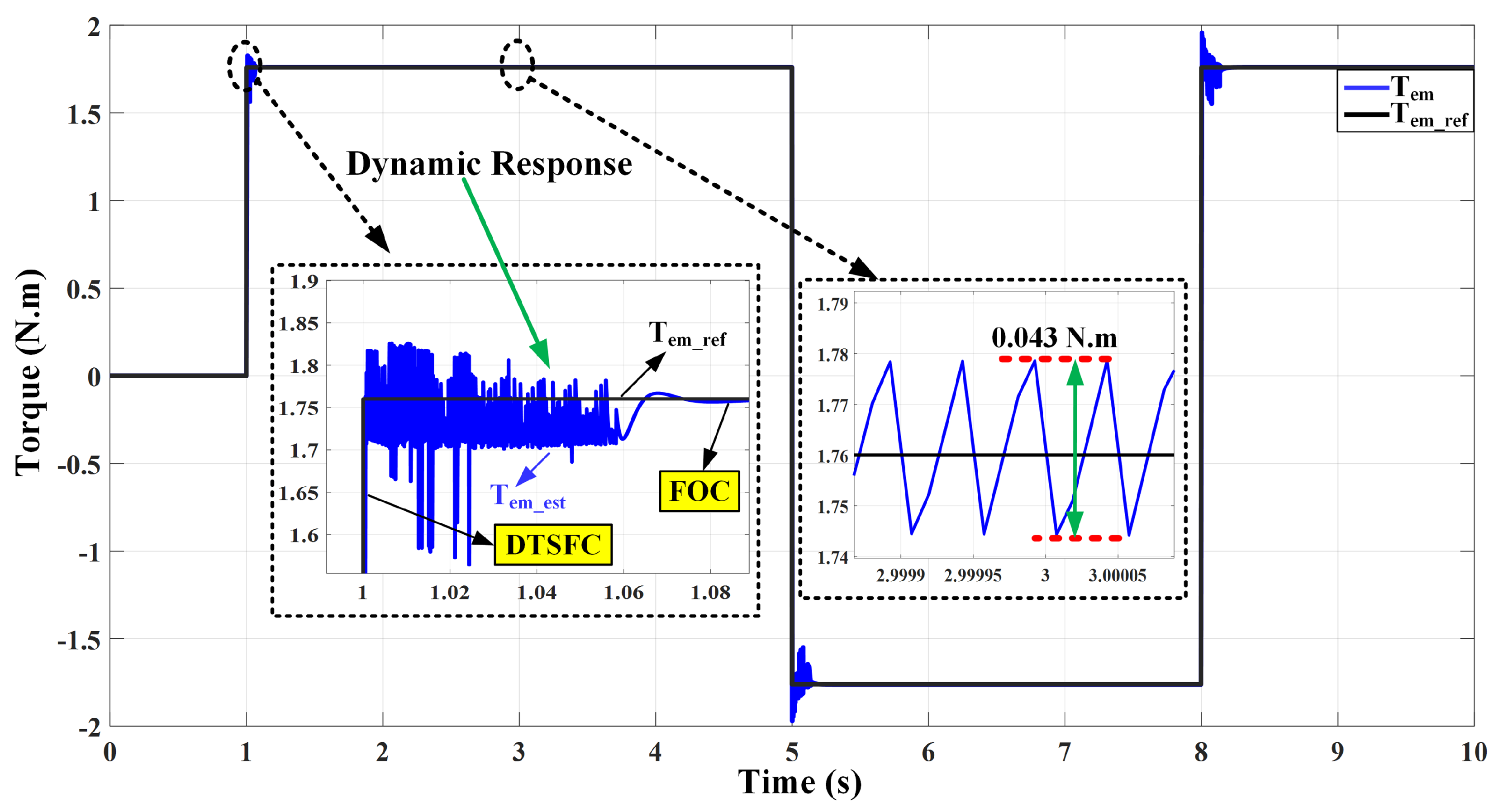
To evaluate the performance of the FOC algorithm, the following parameters were set. The switching frequency of the inverter was set as f P W M = 10 kHz and the sampling time of T s = 50 μs value was selected. The third harmonic injection technique was used to boost the reference voltages within the PWM stage in order to reach the value ( E 3 ) at the inverter output (i.e., an increase of 15.47% in ( E 2 ) is obtained) [57]. Figure 15 and Figure 16 illustrate the responses of rotor flux and torque, depicted in accordance with their rated reference values. The control was carried out at high speed, equivalent to 75% ω n rad/s. The proportional current gain values were set as K P ( α ) I = 100, K P ( β ) I = 400. It is observed that the control of both Φ r and T e m were excellent and matched well to their reference values. It is also apparent that the torque ripples of electromagnetic torque amplitude in the steady state have a small value of about 0.043 N.m, which is roughly 0.024% of T e m n ; this is one of the advantages of the FOC algorithm. However, the transient response value of the torque is slow and spent around 4 ms to reach its steady state condition, as demonstrated in Figure 16. This is due to the FOC method, which is based on the principle of indirect driving of the voltage inverter. Figure 17 shows the responses of stator current components i s α and i s β in the synchronous reference frame. It is evident that they are well regulated between 0.9 and 0.98 A with low ripples. The component i s β is a similar shape to the torque response since the relationship between them is linear when the rotor flux modulus is constant, as noticed in (22). Furthermore, in Figure 18, the sinusoidal three-phase currents are without distortions. Figure 19 and Figure 20 illustrate the responses of the two components of the stator and rotor fluxes vectors in the synchronous reference frame. It can be observed that the real component response of the stator flux vector is similar to the real component of the rotor flux vector in the steady state, while the imaginary component response of the stator flux vector is similar to both component i s β and the electromagnetic torque responses. The imaginary component of the rotor flux vector is zero ( Φ r β = 0 ) , which confirms the correctness of the orientation process towards the ( α a x i s ) .

6.3. Simulation Results of the Combined FOC and DTC Algorithm

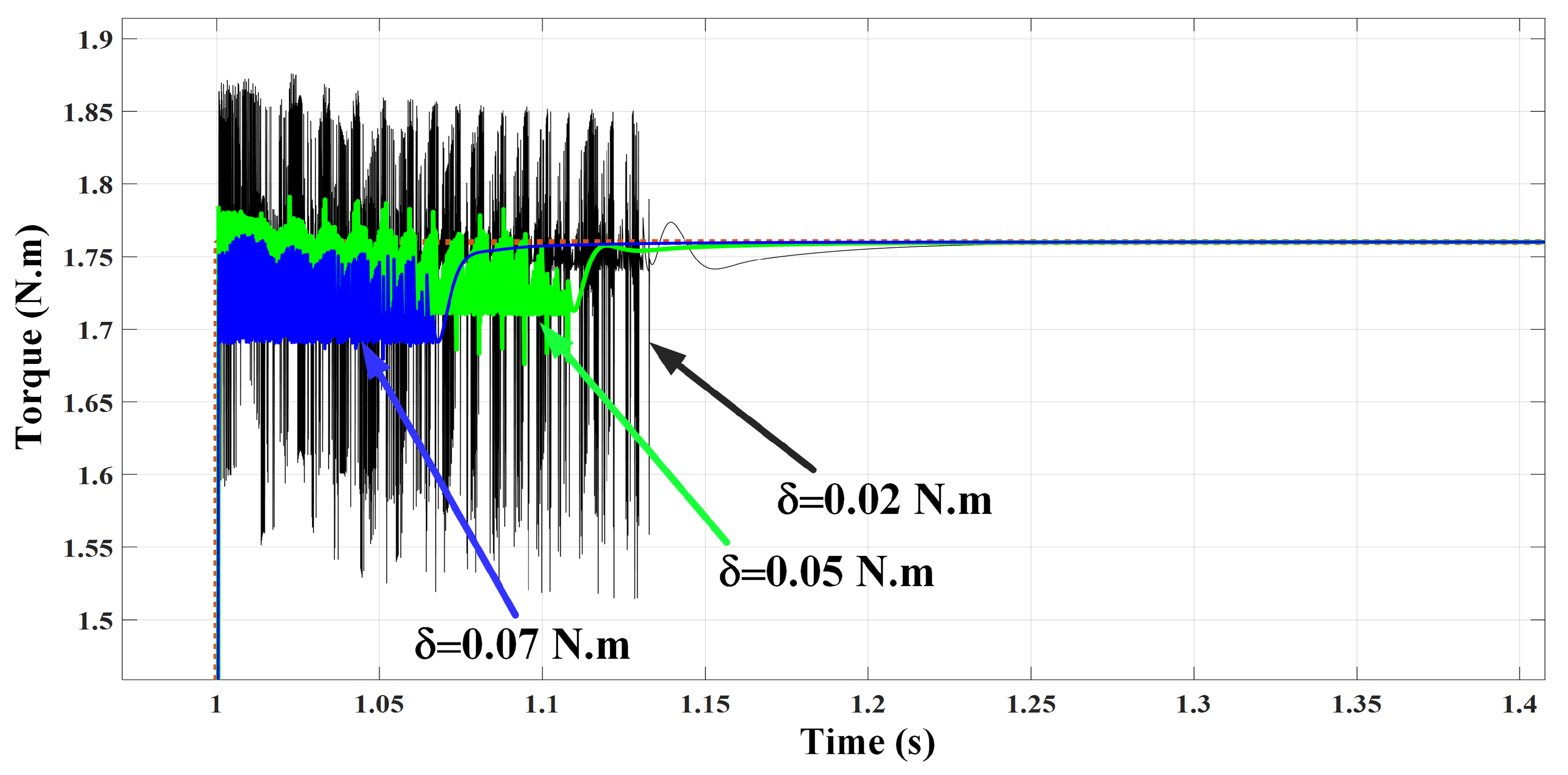
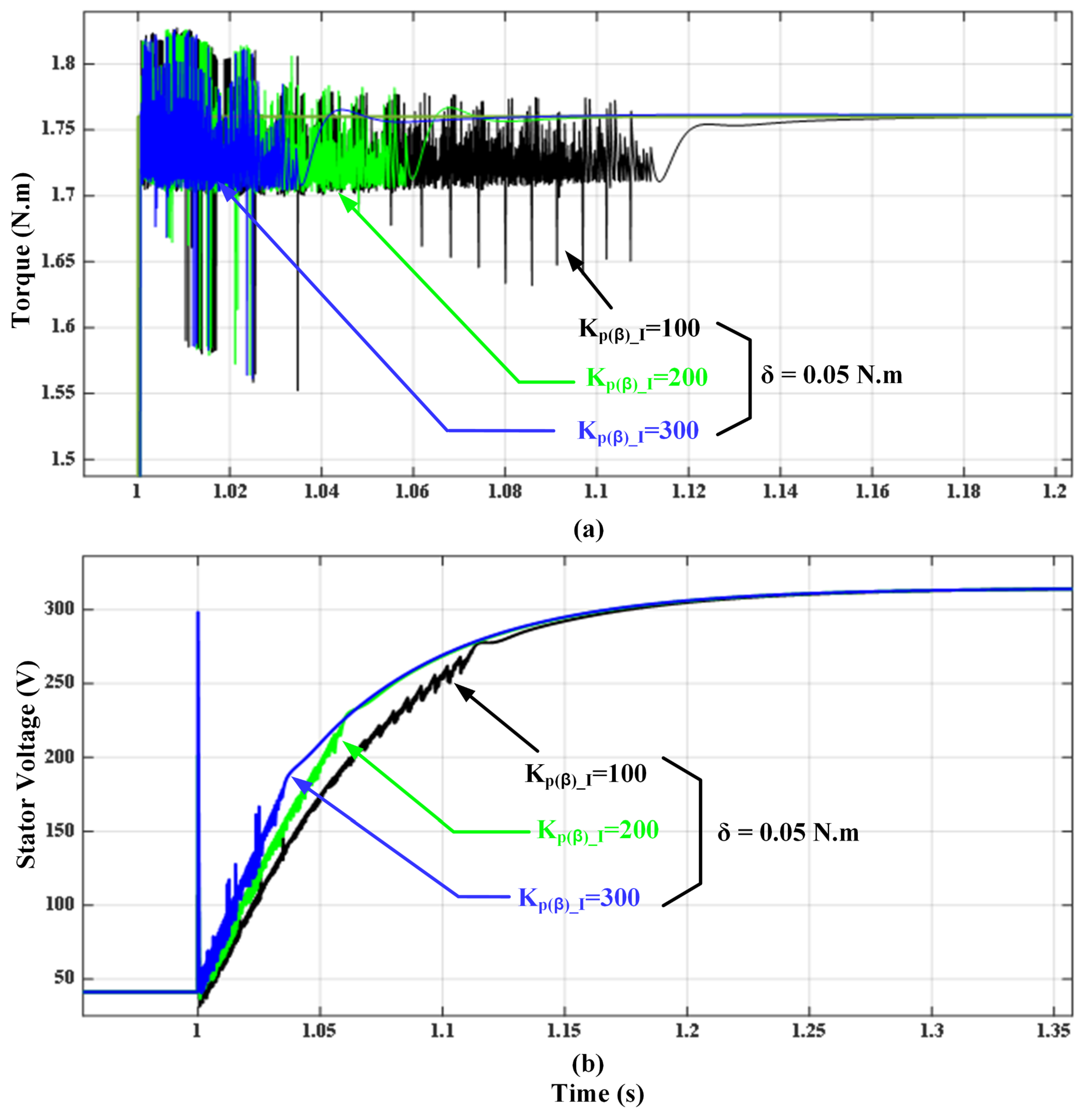
In the proposed scheme, a threshold value was initially selected of 0.05 N.m, and the frequency of the triangle signal in the FOC algorithm was set to f P W M = 10 kHz with a sampling time of T s = 50 μ s. When the FOC-DTC was in operation at a medium speed, at roughly 56% ω n , and a rated reference torque ±1.76 N.m, some disturbances accompanied the transition between DTSFC and FOC for the torque until the steady-state of the torque error stabilized within the predetermined threshold limits, as shown in Figure 21. The stator and rotor flux responses demonstrated in Figure 22 are the same as above scenarios, the transition time between the two algorithms started at 1 s. The value of the rotor flux remained constant at 0.945 Wb, and the stator flux was regulated around its rated reference value of 1.14 Wb just at the moment of applying the DTSFC algorithm. However, the stator flux slightly increased when the FOC algorithm was applied. The three-phase currents are illustrated in Figure 23, where the currents had a sinusoidal shape. Figure 23 shows that the transition procedure went successfully because it is clear that there was no undesirable disturbance of the current signals throughout that time. This indicates that the changeover proceeded smoothly. At the time of switching to the steady state, the distortion in the currents disappeared due to the application of the FOC algorithm, as demonstrated in Figure 23. The electromagnetic torque response in the combined algorithm for several threshold values, δ = 0.02, 0.05, or 0.07 N.m, was shown in Figure 24. An early transition from the DTSFC algorithm to FOC occurred when a large value of this threshold was set. It is worth mentioning that the threshold value should not be so large as to lead to an early transition to the FOC algorithm before the electromagnetic torque signal reaches its reference value. Figure 25 shows that the testbed of the system has been investigated during the transition between the two algorithms and the cause of the disturbances occurs before stabilization. A speed value was given at 0.75 ω n , and the transient response of the torque and the stator vector modulus V s were plotted for three values of the gain K P β I = 100, 200, and 300 with the value of the proportional gain K P α I = 100 at a threshold equal to δ = 0.05 N.m. It is clearly seen that the transient response of the vector V s increased with the increase in the value of this gain ( K P ( β ) I ). Therefore, there are two possible scenarios during the transition between the two algorithms that can be discussed in the following subsection with respect to different gain values.

6.4. Transition Case Results between FOC and DTC Algorithms

6.4.1. Case 1: Assuming a Positive Torque Error

For a value K P β I = 100, while gradually applying a step command of the electromagnetic torque (from zero to the rated value), the control law of the proposed method is to allow the pulses to go through the semiconductor switches of the inverter by DTSFC algorithm prior to FOC in order to achieve high dynamic torque. In the meantime, the torque error decreases due to the increase in the torque reaching its reference value. The control law switches to the FOC algorithm when the torque error comes within the limits of the predetermined threshold value. This causes the transition from a high voltage value (generated by DTSFC) to a lower voltage value (generated by FOC), which has a slow response. The low value of this voltage in FOC will result in a low value of torque, smaller than the value that resulted from the DTSFC algorithm before the time of switching between the two algorithms. As a result, the torque error will increase again instead of decreasing, which leads to exceeding the threshold value, based on the concept of the proposed control that would force switching again to the DTSFC algorithm. The switching process between the two algorithms will continue (in both directions) until the voltage vector VEs ensures that the value of the torque error remains within the threshold ( δ ) limits. In other words, to guarantee that the disturbances are clarified in a short time and fully enter into the steady-state condition.

6.4.2. Case 2: Voltage Vector Switching Is Higher

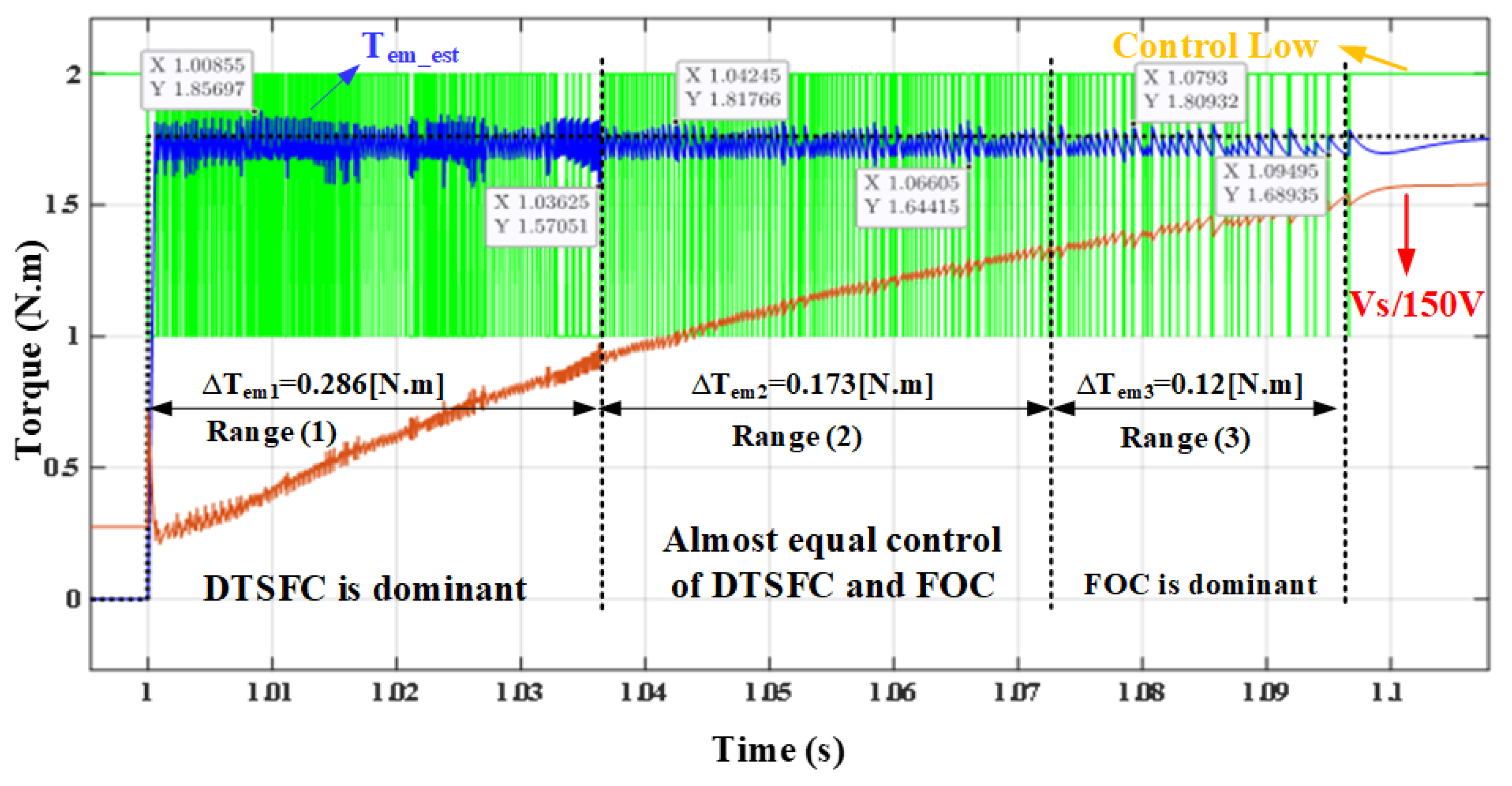
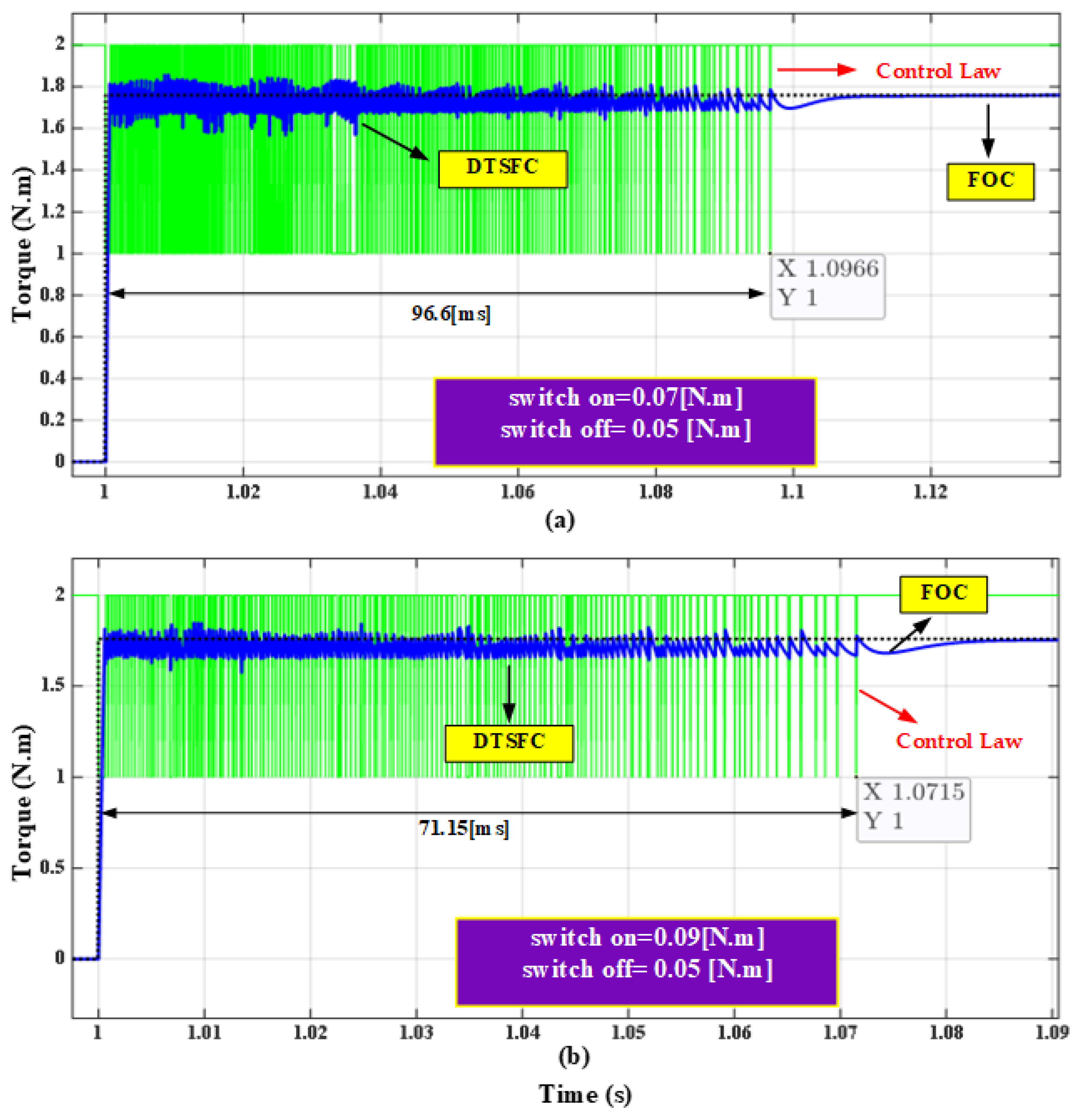
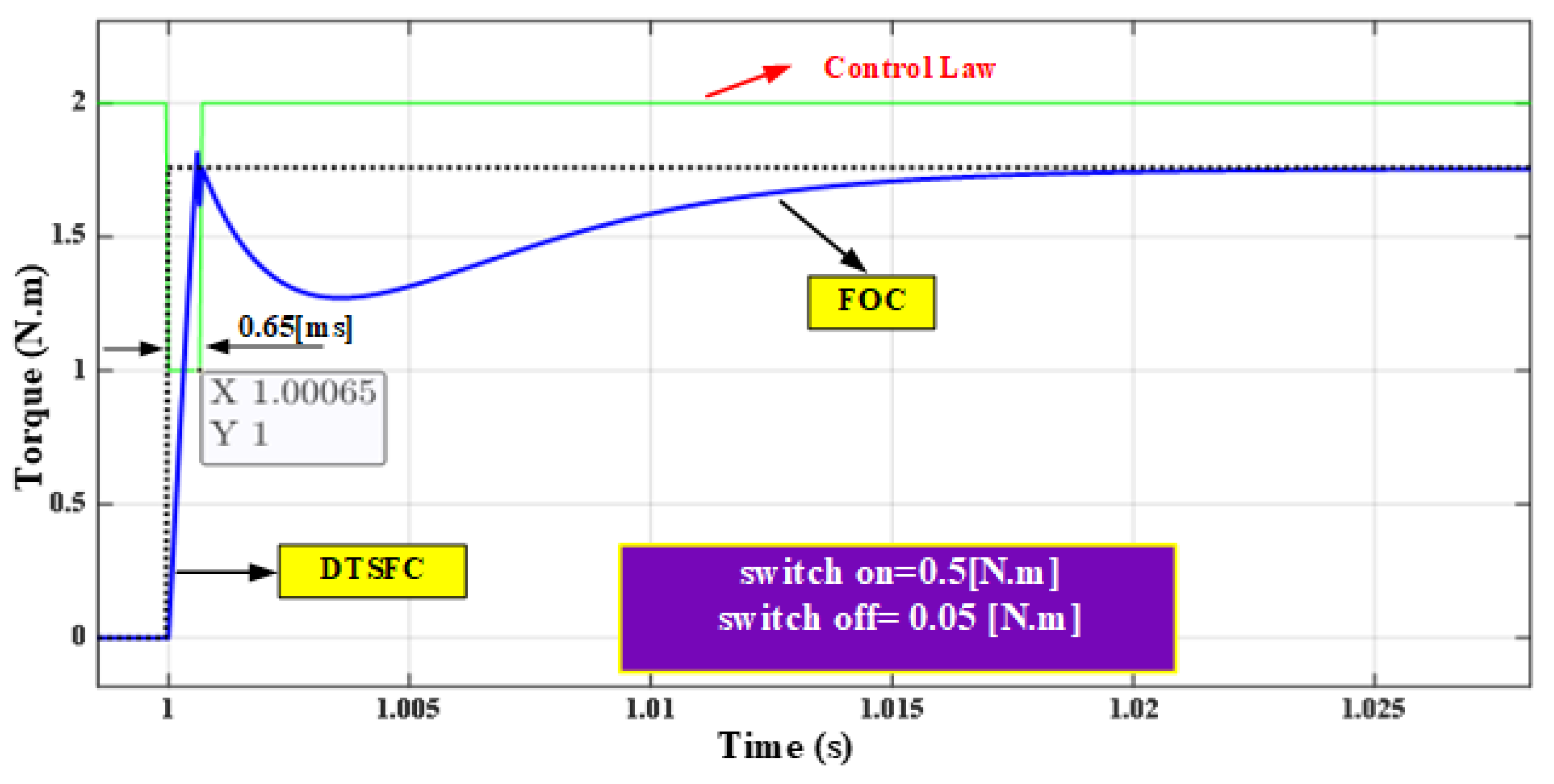
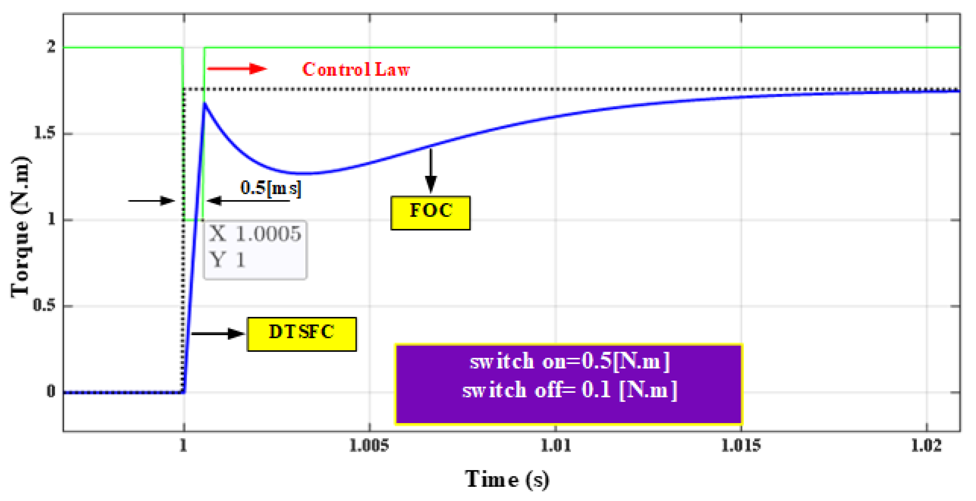
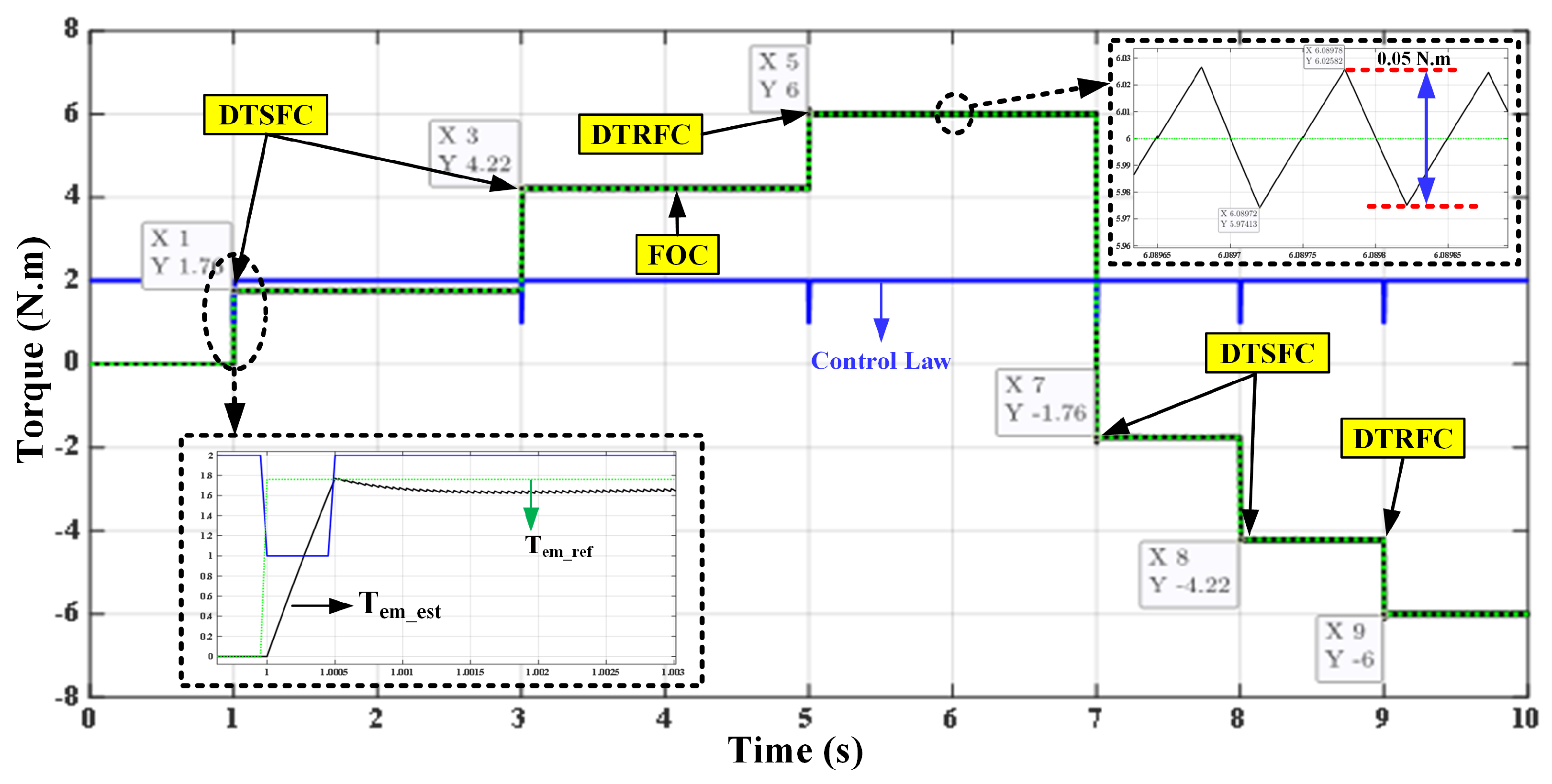
In the case of a gain value assumed to be K P β I = 200 and 300) taking into account the previous scenario, the process will be repeated, but at the time of switching, the voltage vector modulus is at the greatest value compared to case 1. This necessarily means that during this period, the value of the torque error remains less than its value in the first state. Therefore, the amount of perturbation caused by the frequent switching between the two algorithms will be less than the previous state. The above analysis helped out to understand the dynamic working of both algorithms in terms of participating in torque generation within the transient state. Indeed, the value of the voltage vector amplitude generated by the FOC algorithm determines the ratio of its participation in torque production within the transient state. This issue is illustrated in Figure 26, the transient torque response and the voltage vector modulus of the FOC algorithm were plotted. The control decision is assigned a value of range 1 when the DTSFC algorithm is selected and range 2 when the FOC algorithm is selected. It is noted that when the voltage modulus increases, the torque signal’s ripple amplitude decreases. The transient state can be divided into three ranges based on the torque error values, as demonstrated in Figure 26. The ripple’s amplitude value for each range is 0.286, 0.173, and 0.12 N.m, respectively. In the first range, it can be observed that the value of range 1 of the control law is dominant, which means that the DTSFC algorithm is dominant in generating the torque due to the large voltage generated by this algorithm compared to the small voltage produced by FOC. In the second range, the control law oscillates between the two values of range 1 and range 2 almost equally. This means that the torque is generated from each of the two algorithms almost equally with an average value of the amplitude of the ripple. However, in range 3, it is clear that the FOC algorithm has become dominant due to the value of the low ripple of 0.12 N.m. More specifically, the generated voltage by the FOC has ensured that the torque error remains within the threshold limits, as mentioned earlier. In order to improve the performance of the control law for the proposed control, the threshold-based classical method can be replaced by a hysteresis regulator. The selection of such a regulator was due to its stability as well as the act that it allows the designer to be more flexible in choosing the best threshold because it depends on two values (switch-on point, switch-off point). Figure 27 and Figure 28 show the torque response in the combined algorithm for different values of the switch-on and switch-off points of the hysteresis regulator. The control law of the proposed control represents the output of the hysteresis regulator, which is expressed in either range 1 or 2 based on the selected algorithm (DTSFC or FOC). In order to demonstrate the effect of the switch on and off of the hysteresis regulator, changes were made in one of them while the other value was fixed, as shown in Figure 27a,b and vice versa, Figure 28 and Figure 29. According to Figure 27a,b, two different values for switch-on were selected, 0.07 N.m or 0.09 N.m, while switch-off was fixed, 0.05 N.m. The switching time of the torque was 96.6 ms with the small value of switch-on = 0.07 N.m. However, the time decreased to 71.15 ms with a large switch-on value of 0.09. In Figure 28 and Figure 29, two different values of switch-off were set, 0.05 N.m or 0.1 N.m, while the switch-on was fixed at 0.5 N.m. The selection of the values in Figure 28 was satisfactory because the torque could reach its reference value. However, the selected values in Figure 29 were not reasonable because the FOC algorithm arrived early, which forced the torque to not reach its reference value. The last case led to the loss of the high dynamics resulting from the DTC algorithm. In order to validate the performance of the proposed combined algorithm FOC-DTC over the wide torque operation range, the three algorithms were allowed to participate in torque generation. There was a wide range of torque operations applied in Figure 30 and Figure 31, as shown in Table 2, which illustrated torque references with various values. The values of the thresholds were set as switch-on = 0.5 N.m and switch-off = 0.05 N.m.
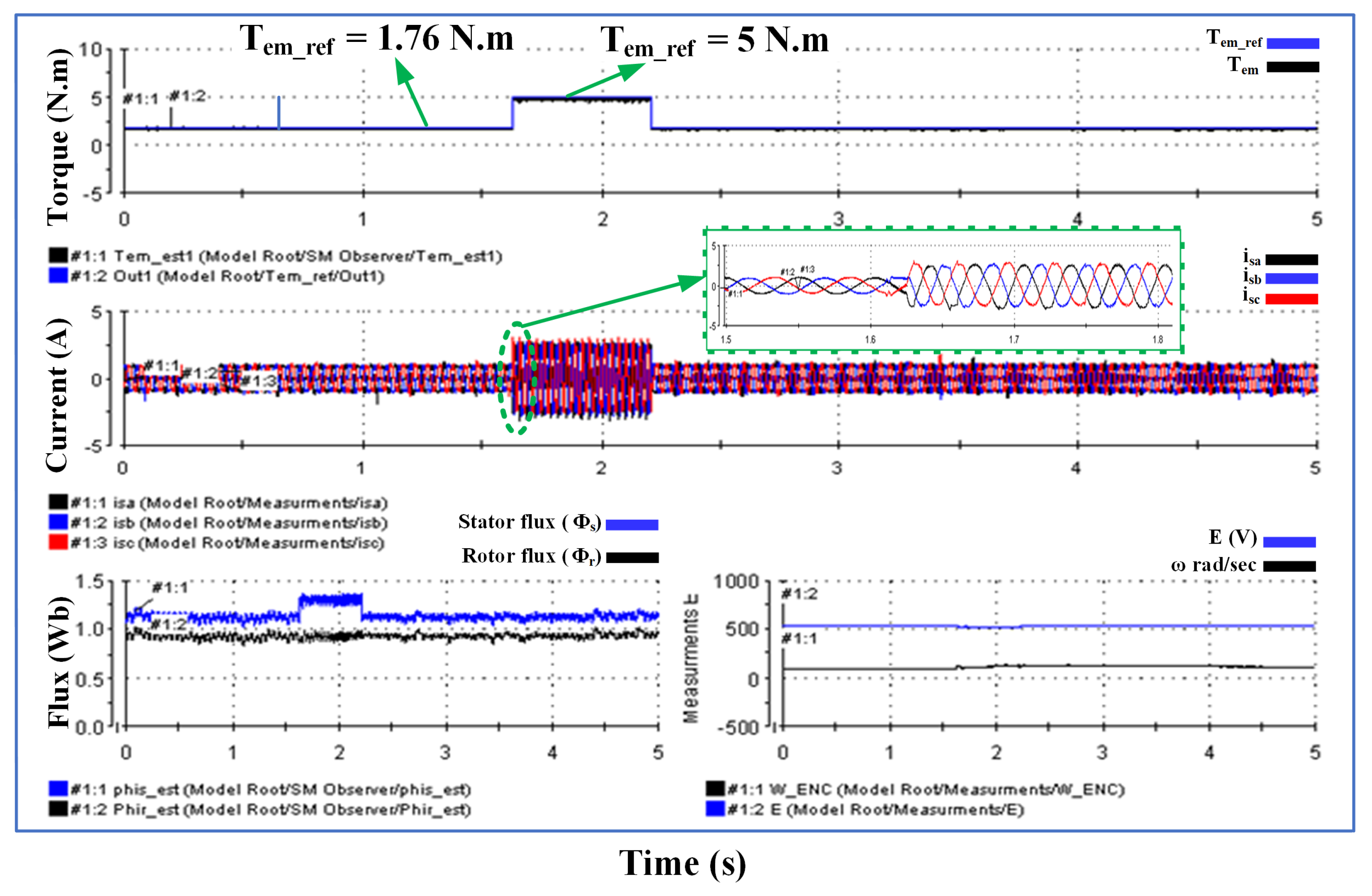
The proportional gains were set as K P α , β I = 100 and 400. It can be observed that, for the transient state, DTSFC was allowed to work within a reference torque range and should not exceed the breakdown value of 4.22 N.m, as shown in Figure 30. However, DTRFC was allowed to work once the torque exceeded the breakdown torque. More specifically, with a reference torque equalling T e m r e f = 6 N.m, the torque regulation was achieved. The rotor flux was regulated around the rated value of 0.945 Wb along the wide operation range. However, the stator flux increased or decreased according to the torque demand, as shown in Figure 31.

7. Experimental Results Using a dSPACE-DS1103-Based Platform

In order to support the simulation results of the analytical analysis performed over the entire speed range, a dedicated experiment was performed by using an interface device called a dSPACE-DS1103 card. The experiments were performed on a squirrel cage three-phase induction motor of 50 Hz, 230/400 V, and 0.25 kW. The motor was fed from a 22.8 kVA three-phase Semikron inverter. The dc-link voltage was set as 550 V. An incremental encoder of 1024 pulses per revolution was used to measure the speed. The three currents of the three-phase motor were measured using only two sensors. The two components of the voltage vector were estimated by measuring the voltage of the dc-link, E, and the pulses of the inverter. The platform was pictured as demonstrated in Figure 32.
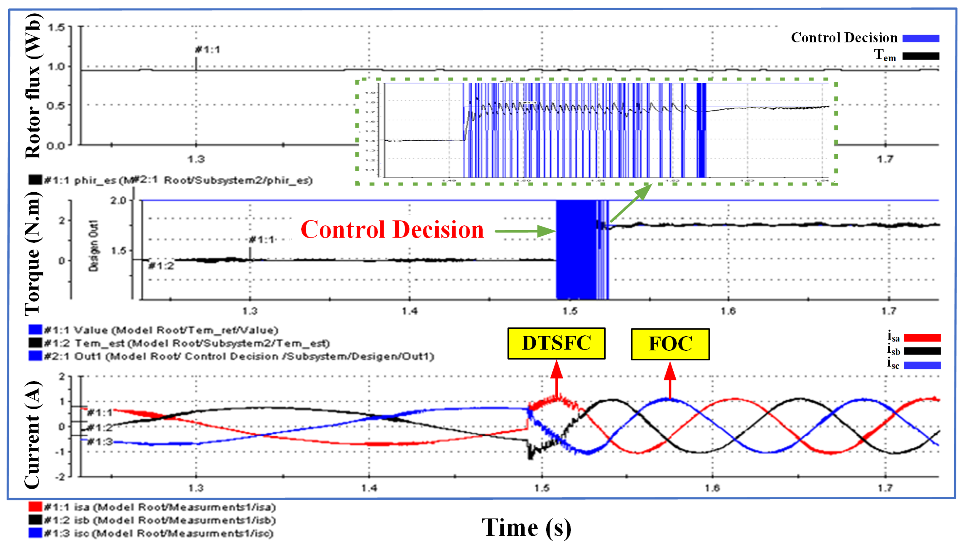
The test rig consists of all employed equipment, including the dSPACE DS1103 card. To compare the performance of the DTSFC versus DTRFC, the experimental results are shown in Figure 33 and Figure 34. DTSFC was tested for successive steps of the reference torque given. It is illustrated that the performance of DTSFC remained satisfactory as long as the required reference torque did not exceed the critical value of 4.22 N.m. However, DTSFC failed when this value was exceeded, and the successive steps of the reference torque were accompanied by a drop in the rotor flux value. The stator flux remained regulated around the reference value of 1.14 Wb. Regarding the DTRFC algorithm, the performance was tested for successive steps of the reference torque. It was proven that the DTRFC algorithm was able to provide the desired torque in accordance with the required reference steps as long as the inverter dc-link voltage allows. The stator flux modulus grew with the increase in the required reference torque, while the rotor flux modulus remained regulated around its reference value of 0.945 Wb. The results in Figure 33 and Figure 34 adequately agree with the simulation results shown in Figure 7, Figure 8, Figure 11, and Figure 12. In Figure 35, the experimental result of the implemented FOC-DTC scheme shows that the speed was set at 0.75 ω n with a sampling time of T s = 50 μ s, and the PWM frequency was f P W M = 20 kHz. The reference value of the rotor flux was 0.945 Wb. To test the robustness of the proposed scheme, the reference torque was instantly changed from 0.88 N.m to 1.76 N.m at 1.48 s. It is proven that the transition process took place well within the transient state after several disturbances in the value of the control decision. The rotor flux and torque are well controlled around the above reference values, and the three-phase currents have a sinusoidal shape. Clearly, the experimental results are in good agreement with the analytical results presented in Figure 21 and Figure 22, giving full validation to the adopted approach. Figure 36 shows the torque response in the combined algorithm for different values of the switch-on point and switch-off point of the hysteresis regulator. The control law representing the output of the hysteresis regulator is expressed in either range 1 or 2 depending on the selected algorithm (DTC or FOC). The same two values are selected in Figure 27, Figure 28 and Figure 29 where repetitive steps are addressed, i.e., switch-off was changed (switch-off = 0.05 or 0.1 N.m) while switch-on was fixed (switch-on = 0.5 N.m). It is noted that the disturbance in the transient state was greatly reduced, and the transition was fast between DTC and FOC. Therefore, the experimental implementation by using dSPACE DS1103 fully agreed with the simulation results presented in Figure 27, Figure 28 and Figure 29.

8. Robustness and Evaluation against Previous and Recent Related Techniques

To verify the feasibility and the effectiveness of the proposed algorithm, its performance is compared with previous and up-to-date related approaches in the literature review, which are specified in the following work reference [24,25,26,27,28,29,30,31,32,33,34,35,36]. Table 3 represents seven work references deemed to be worthy of comparison with the proposed control scheme. The most relatable case studies towards the proposed control scheme are in [24,31], while the rest of the articles clearly perform worse than the proposed algorithm because they all operate at a variable switching frequency, as well as are unable to generate a large torque beyond the critical torque. Study [24] contained four optional gains, which created difficulty in the synthesis process with the changing operating conditions as well as the need for orientation over the whole range of the operation. However, the proposed method had only two optional gains. In addition, the lack of simplicity in terms of orientation within the transient state and nominal torque range. Study [31] showed that the system suffers from a slow torque transient, the switching frequency is not always constant, and its incapacity to generate torque above the critical torque. The comparison pointed out that the proposed method has provided valuable results compared to the corresponding literature in terms of low flux and torque ripples, high torque production, constant switching frequency, and simplicity.
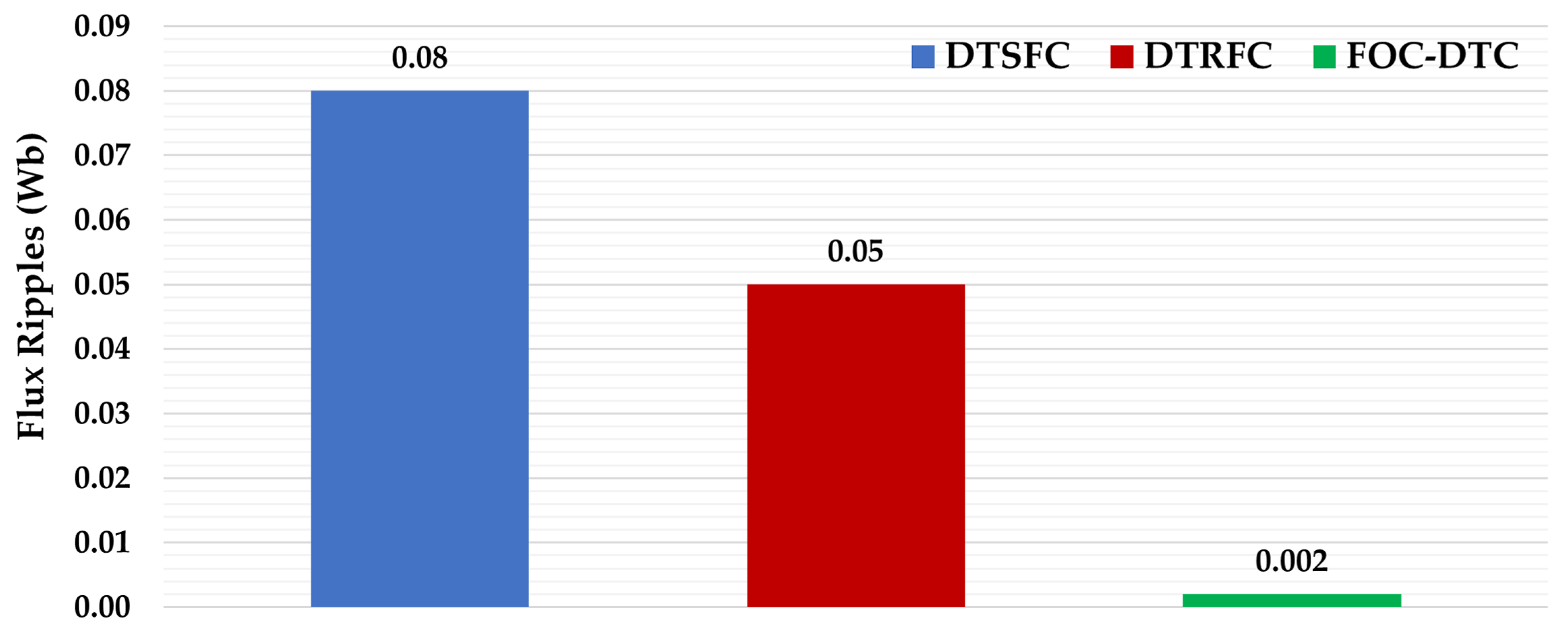
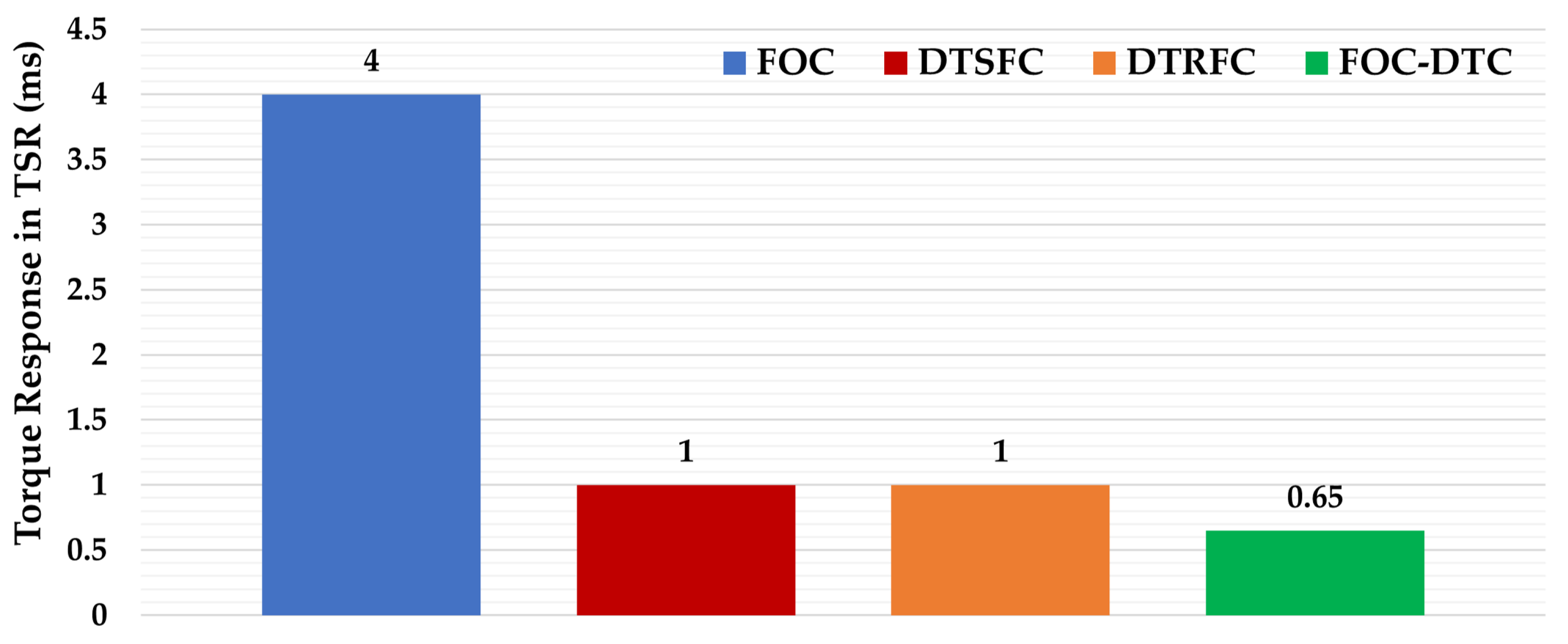
For further clarification of the indicated strategies in this article, a numerical comparison is shown in Figure 37, Figure 38 and Figure 39 in terms of flux ripples, torque ripples, and torque response in TSR, respectively. Figure 37 shows that the proposed combined strategy produced the lowest value in magnetic flux ripples at 0.002 Wb compared to the other two strategies, DTSFC and DTRFC. Similarly, according to Figure 38, the proposed strategy produced fewer torque ripples at 0.043 N.m compared to the other two strategies, DTSFC and DTRFC. Figure 39 demonstrates that the proposed combined technique is much faster in terms of torque response in TSR at 0.65 ms compared to FOC, DTSFC, and DTRFC.

9. Conclusions

In this article, an analytical investigation of a novel combined algorithm, namely, FOC-DTC, of induction motor drives were performed at transient and steady states over a wide range of torque operations. The working principle of the proposed scheme was based on the selection of DTSFC or DTRFC at the transient state in accordance with the defined reference torque. In contrast, FOC was switched smoothly at the steady-state condition based on a defined torque error. The contributions of the proposed scheme were successfully achieved and are summarized as follows:
  • Offered high dynamics of flux and torque due to the use of the DTSFC algorithm within the nominal torque range of 0.5 ms.
  • Enabled the generation of high torque beyond the breakdown torque due to the use of the DTRFC algorithm 6/1.76 N.m * 100 = 340% T e m n .
  • Excellent, low steady-state error of torque and torque ripple that was reduced to a great extent due to the use of the FOC algorithm at 0.05 N.m and 0.028% T e m n .
  • Excellent transition between the transient state and steady state with the best values of switch-on= 0.5 N.m, switch-off = 0.1 N.m.
  • Constant switching frequency was achieved at f p w m = 10 kHz due to the use of the FOC algorithm during the steady-state condition.
  • The results of the experiment distinguished the findings of the proposed study, which provided full validation for the adopted methodology and were in complete agreement with the simulated outcomes.
Despite the fact that the FOC algorithm performed well in the proposed scheme, the transient response value of the torque was slow and spent around 4 ms to reach its steady state. It is worth mentioning that the simplicity of the proposed technique was preserved since there is no requirement to modify the typical DTC or FOC structure. This particular feature is not involved in any article of the literature review. The simulation results and a full comparison with previous and the most recent research were presented, which then verified the superiority and effectiveness of the proposed scheme. Furthermore, the proposed approach maintains simplicity with a low cost solution for real implementation.
Future work will explore how to accurately control decisions in the proposed method and how to further design more robust approach for combined DTC and FOC strategies when taking into account the error and change in the error of the torque signal by means of intelligent techniques. This work can be developed in the future by developing the control decision so that it could contain a neural network that can make the decision not only based on the torque error but also on the change in the torque error, which will give higher dynamics with fewer fluctuations within the transient state. It is also possible to conduct in-depth studies on the change in motor parameters and their impact on the performance of the driving system.

Author Contributions

Conceptualization, M.E., F.A. and M.M.A.; methodology, M.E., F.A. and M.M.A.; software, M.E. and M.M.A.; validation, M.E., F.A. and M.M.A.; formal analysis, M.E. and M.M.A.; investigation, M.E. and M.M.A.; resources, M.E. and M.M.A.; data curation, M.E. and M.M.A.; writing—original draft preparation, M.E. and M.M.A.; writing—review and editing, M.E., F.A. and M.M.A.; visualization, M.E., F.A. and M.M.A.; supervision, M.E., F.A. and M.M.A.; project administration, M.E.; funding acquisition, M.E. All authors have read and agreed to the published version of the manuscript.

Funding

The Open-Access (OA) charges of this work are funded by the Cardiff University, Institutional OA Fund.

Institutional Review Board Statement

Not applicable.

Informed Consent Statement

Not applicable.

Data Availability Statement

Not applicable.

Acknowledgments

The authors would like to thank the School of Engineering, Cardiff University, for supporting this research work by funding the APC towards publishing this paper.

Conflicts of Interest

The authors declare no conflict of interest.

Appendix A

Table A1. Parameters of the induction motor.
VariableUnit Value
Nominal voltage230/400 V
Phase resistance stator R s = 45.83 Ω
Phase resistance rotor R r = 31 Ω
Phase inductance stator L s = 1.24 H
Phase inductance rotor L r = 1.11 H
Mutual inductance L m = 1.05 H
InertiaJ = 0.006 kg.m 2
Friction factorf = 0.001 N.m. sec/rad
Number of poles pairsp = 2
Nominal stator flux Φ s = 1.14 Wb
Nominal rotor flux Φ r = 0.945 Wb
Nominal power P n = 0.25 kW
Nominal frequencyF = 50 Hz
Nominal speed ω n = 282 rad/s
Nominal torque T e m = 1.76 N.m

Appendix B

Table A2. Parameters of PI current controller using the trial and error method.
Kp and Ki Gains for ( α β ) FrameCalculation of Kp and Ki Gains
K P ( α ) I = 100 K I ( α ) I = a 5 . K P ( α ) I
K P ( β ) I = 100, 200, 300 and 400. K I ( β ) I = a 5 . K P ( β ) I

Appendix C. Motor Constants

a 1 = R r L r , a 2 = L m R r L r , a 3 = L m R r σ L s L r 2
a 4 = L m σ L s L r , a 5 = L r 2 R s + L m 2 R r σ L s L r 2 , b = 1 σ L s

Appendix D

Table A3. Abbreviations.
AbbreviationDefinition
IMInduction Motor
DTSFCDirect Torque ans Stator Flux Control
DTRFCDirect Torque and Rotor Flux Control
FOCField-Oriented Control
VSIVoltage Source Inverter
VEsVoltage Vectors
HCsHysteresis Controllers
LUTLookup Table
PWMPulse Width Modulation
TSRTransient State Response
SSRSteady State Response
RefReference

Appendix E

To calculate the reference value of the stator and rotor flux, the following equations are used, considering a stationary reference frame:
Φ s = 2 3 · V s ω r = 2 3 · 311 2 π · 50 = 1.212 W b .
Due to the effect of the stator resistance with loading, the previous value drops to 1.14 Wb. Therefore, Φ s r e f = 1.14 Wb.
To calculate the reference rotor flux, the following equation is used after orienting the rotor flux vector towards the α axis in the synchronous reference frame:
Φ r = L m L s · 1 1 + ( σ τ r ω r ) · Φ s = 1.05 1.24 · 1 1 + ( 1.99 · 0.0358 · 32.15 ) · 1.14 = 0.945 Wb .
where
ω r = ω s ω n = 2 π · 50 282 = 32.15 r a d / s .
Therefore, Φ r r e f = 0.945 Wb.

References

  1. Priyanka, C.P.; Jagadanad, G. Inter-Turn Fault Analysis of Three Phase Induction Motor. In Proceedings of the 2020 IEEE 9th Power India International Conference (PIICON), Sonepat, India, 28 February–1 March 2020. [Google Scholar] [CrossRef]
  2. Shukla, S.; Singh, B. Single-Stage PV Array Fed Speed Sensorless Vector Control of Induction Motor Drive for Water Pumping. IEEE Trans. Ind. Appl. 2018, 54, 3575–3585. [Google Scholar] [CrossRef]
  3. Boulmane, A.; Zidani, Y.; Belkhayat, D.; Bouchouirbat, M. A GA-based adaptive mechanism for sensorless vector control of induction motor drives for urban electric vehicles. Turk. J. Electr. Eng. Comput. Sci. 2020, 28, 1731–1746. [Google Scholar] [CrossRef]
  4. Petri, A.M.; Petreus, D. Vector Control of Induction Machine Used in Electric Vehicle. In Proceedings of the 2020 43rd International Spring Seminar on Electronics Technology (ISSE), Demanovska Valley, Slovakia, 14–15 May 2020. [Google Scholar] [CrossRef]
  5. Aktas, M.; Awaili, K.; Ehsani, M.; Arisoy, A. Direct torque control versus indirect field-oriented control of induction motors for electric vehicle applications. Eng. Sci. Technol. Int. J. 2020, 23, 1134–1143. [Google Scholar] [CrossRef]
  6. Benbouhenni, H.; Bizon, N. Improved Rotor Flux and Torque Control Based on the Third-Order Sliding Mode Scheme Applied to the Asynchronous Generator for the Single-Rotor Wind Turbine. Mathematics 2021, 9, 2297. [Google Scholar] [CrossRef]
  7. Casadei, D.; Profumo, F.; Serra, G.; Tani, A. FOC and DTC: Two viable schemes for induction motors torque control. IEEE Trans. Power Electron. 2002, 17, 779–787. [Google Scholar] [CrossRef] [Green Version]
  8. Idris, N.R.N.; Yatim, A.H.M. Direct torque control of induction machines with constant switching frequency and reduced torque ripple. IEEE Trans. Ind. Electron. 2004, 51, 758–767. [Google Scholar] [CrossRef]
  9. Fekih, A.; Mobayen, S.; Chen, C.C. Adaptive robust fault-tolerant control design for wind turbines subject to pitch actuator faults. Energies 2021, 14, 1791. [Google Scholar] [CrossRef]
  10. Korkmaz, F.; Topaloğlu, İ.; Çakir, M.F.; Gürbüz, R. Comparative performance evaluation of FOC and DTC controlled PMSM drives. In Proceedings of the 2020 IEEE 4th International Conference on Power Engineering, Energy and Electrical Drives, Istanbul, Turkey, 13–17 May 2013. [Google Scholar] [CrossRef]
  11. Al-Mamoori, D.H.; Al-Tameemi, Z.H.; Jumaa, F.A.; Neda, O.M.; Al-Ghanimi, M.G. A Comparative Study of DTC-SVM and FOC-SVM Control Techniques of Induction Motor Drive. J. Eng. Appl. Sci. 2019, 14, 2135–2140. [Google Scholar] [CrossRef] [Green Version]
  12. Meesala, R.E.K.; Thippiripati, V.K. An improved direct torque control of three-level dual inverter fed open-ended winding induction motor drive based on modified look-up table. IEEE Trans. Power Electron. 2020, 35, 3906–3917. [Google Scholar] [CrossRef]
  13. Wang, M.; Sun, D.; Ke, W.; Nian, H. A Universal Lookup Table-Based Direct Torque Control for OW-PMSM Drives. IEEE Trans. Power Electron. 2021, 36, 6188–6191. [Google Scholar] [CrossRef]
  14. Suresh, S.; Rajeevan, P.P. Virtual Space Vector-Based Direct Torque Control Schemes for Induction Motor Drives. IEEE Trans. Ind. Appl. 2020, 56, 2719–2728. [Google Scholar] [CrossRef]
  15. Yang, G.; Yang, J.; Li, S.; Wang, Y.; Hussain, H.; Deng, R.; Yan, L. A Sequential Direct Torque Control Scheme for Seven-Phase Induction Machines Based on Virtual Voltage Vectors. IEEE Trans. Ind. Appl. 2021, 57, 3722–3734. [Google Scholar] [CrossRef]
  16. Muduli, U.R.; Behera, R.K.; Hosani, K.A.; Moursi, M.S.E. Direct Torque Control With Constant Switching Frequency for Three-to-Five Phase Direct Matrix Converter Fed Five-Phase Induction Motor Drive. IEEE Trans. Power Electron. 2022, 37, 11019–11033. [Google Scholar] [CrossRef]
  17. Deng, W.; Li, H.; Rong, J. A Novel Direct Torque Control of Matrix Converter-Fed PMSM Drives Using Dynamic Sector Boundary for Common-Mode Voltage Minimization. IEEE Trans. Ind. Electron. 2021, 68, 70–80. [Google Scholar] [CrossRef]
  18. Fan, B.; Fu, Z.; Liu, L.; Fu, J. The full-order state observer speed-sensorless vector control based on parameters identification for induction motor. Meas. Control 2019, 52, 202–211. [Google Scholar] [CrossRef] [Green Version]
  19. Khan, M.R.; Iqbal, A. Experimental investigation of five-phase induction motor drive using extended Kalman-filter. Asian Power Electron. J. 2009, 3, 1–7. [Google Scholar]
  20. Khadar, S.; Abu-Rub, H.; Kouzou, A. Sensorless Field-Oriented Control for Open-End Winding Five-Phase Induction Motor With Parameters Estimation. IEEE Open J. Ind. Electron. Soc. 2021, 1, 266–279. [Google Scholar] [CrossRef]
  21. Wang, F.; Mei, X.; Tao, P.; Kennel, R.; Rodriguez, J. Predictive field-oriented control for electric drives. Chin. J. Electr. Eng. 2017, 3, 73–78. [Google Scholar] [CrossRef]
  22. Farhan, N.S.; Humod, A.T.; Hasan, F. Field Oriented Control of AFPMSM for Electrical Vehicle Using Adaptive Neuro-Fuzzy Inference System (ANFIS). Eng. Technol. J. 2021, 39, 1571–1582. [Google Scholar] [CrossRef]
  23. Monmasson, E.; Robyns, B.; Mendes, E.; Fornel, B.D. Dynamic reconfiguration of control and estimation algorithms for induction motor drives. In Proceedings of the Industrial Electronics, ISIE 2002, IEEE International Symposium; L’Aquila, Italy, 8–11 July 2002. [CrossRef]
  24. Naassani, A.A.; Monmasson, E.; Louis, J.P. Synthesis of direct torque and rotor flux control algorithms by means of sliding-mode theory. IEEE Trans. Ind. Electron. 2005, 52, 785–799. [Google Scholar] [CrossRef]
  25. Vaez-Zadeh, S.; Jalali, E. Combined vector control and direct torque control method for high performance induction motor drives. Energy Convers. Manag. 2007, 48, 3095–3101. Available online: https://www.sciencedirect.com/science/article/pii/S0196890407001409 (accessed on 24 September 2007). [CrossRef]
  26. Jiang, Z.; Hu, S.; Cao, W. A New Fuzzy Logic Torque Control Scheme Based on Vector Control and Direct Torque Control for Induction Machine. In Proceedings of the 2008 3rd International Conference on Innovative Computing Information and Control, Dalian, China, 18–20 June 2008. [Google Scholar] [CrossRef]
  27. Elgbaily, M.; Anayi, F.; Packianather, M. Performance Improvement Based Torque Ripple Minimization for Direct Torque Control Drive Fed Induction Motor Using Fuzzy Logic Control, Control, Instrumentation and Mechatronics: Theory and Practice; Springer Nature Singapore Pte Ltd.: Singapore, 2022; pp. 416–428. [Google Scholar]
  28. Vaez-Zadeh, S.; Daryabeigi, E. Combined vector and direct torque control methods for IPM motor drives using emotional controller (BELBIC). In Proceedings of the 2011 2nd Power Electronics, Drive Systems and Technologies Conference, Tehran, Iran, 16–17 February 2011. [Google Scholar] [CrossRef]
  29. Boulghasoul, Z.; Elbacha, A.; Elwarraki, E.; Yousfi, D. Combined Vector Control and Direct Torque Control an experimental review and evaluation. In Proceedings of the 2011 International Conference on Multimedia Computing and Systems, Washington, DC, USA, 7–9 April 2011. [Google Scholar] [CrossRef]
  30. El Kharki, A.; Boulghasoul, Z.; Et-Taaj, L.; Elbacha, A. A New Intelligent Control Strategy of Combined Vector Control and Direct Torque Control for Dynamic Performance Improvement of Induction Motor Drive. J. Electr. Eng. Technol. 2022. Available online: https://link.springer.com/article/10.1007/s42835-022-01086-3 (accessed on 24 September 2007). [CrossRef]
  31. Talib, M.H.N.; Ibrahim, Z.; Rahim, N.A.; Yaakop, N.M. Development of combined vector and Direct Torque Control methods for independent two induction motor drives. In Proceedings of the 2012 IEEE International Power Engineering and Optimization Conference Melaka, Melaka, Malaysia, 6–7 June 2012. [Google Scholar] [CrossRef]
  32. Vasarhelyi, J.; Imecs, M.; Szabo, C.; Incze, I.I. Run-Time Reconfiguration of Tandem Inverter for Induction Motor Drives. In Proceedings of the 2020 IEEE 12th International Power Electronics and Motion Control Conference, Nanjing, China, 29 November–2 December 2020. [Google Scholar] [CrossRef]
  33. Vasarhelyi, J.; Incze, I.I.; Imecs, M.; Szabo, C. Improved Starting of the Induction Motor Fed by a Run-Time Reconfigurable Frequency Converter. In Proceedings of the 2006 International Conference on Intelligent Engineering Systems, International Conference on Intelligent Engineering Systems, London, UK, 26–28 June 2006. [Google Scholar] [CrossRef]
  34. Mahfoud, S.; Derouich, A.; Iqbal, A.; El Ouanjli, N. ANT-colony optimization-direct torque control for a doubly fed induction motor: An experimental validation. Energy Rep. 2022, 8, 81–98. [Google Scholar] [CrossRef]
  35. Elgbaily, M.; Anayi, F.; Packianather, M. Genetic and particle swarm optimization algorithms based direct torque control for torque ripple attenuation of induction motor. Mater. Today Proc. 2022, 67, 577–590. [Google Scholar] [CrossRef]
  36. Alsofyani, I.M.; Idris, N.R.N.; Lee, K. Dynamic Hysteresis Torque Band for Improving the Performance of Lookup-Table-Based DTC of Induction Machines. IEEE Trans. Power Electron. 2018, 33, 7959–7970. [Google Scholar] [CrossRef]
  37. Casadei, D.; Serra, G.; Tani, K. Implementation of a direct control algorithm for induction motors based on discrete space vector modulation. IEEE Trans. Power Electron. 2000, 15, 769–777. [Google Scholar] [CrossRef]
  38. Hajian, M.; Soltani, J.; Markadeh, G.A.; Hosseinnia, S. Adaptive Nonlinear Direct Torque Control of Sensorless IM Drives With Efficiency Optimization. IEEE Trans. Ind. Electron. 2010, 57, 975–985. [Google Scholar] [CrossRef]
  39. Lai, Y.-S.; Chen, J.-H. A new approach to direct torque control of induction motor drives for constant inverter switching frequency and torque ripple reduction. IEEE Trans. Energy Convers. 2001, 16, 220–227. [Google Scholar] [CrossRef]
  40. Buja, Y.G.; Menis, R. Steady-State Performance Degradation of a DTC IM Drive Under Parameter and Transduction Errors. IEEE Trans. Ind. Electron. 2008, 55, 1749–1760. [Google Scholar] [CrossRef]
  41. Casadei, D.; Serra, G.; Tani, A. Steady-state and transient performance evaluation of a DTC scheme in the low speed range. IEEE Trans. Power Electron. 2001, 16, 846–851. [Google Scholar] [CrossRef]
  42. Casadei, D.; Serra, G.; Tani, A.; Zarri, L. Assessment of direct torque control for induction motor drives. Bull. Pol. Acad. Sci. Tech. Sci. 2006, 54, 237–254. [Google Scholar]
  43. Ambrozic, V.; Buja, G.S.; Menis, R. Band-constrained technique for direct torque control of induction motor. IEEE Trans. Ind. Electron. 2004, 51, 776–784. [Google Scholar] [CrossRef]
  44. Mathapati, S.; Bocker, J. Analytical and Offline Approach to Select Optimal Hysteresis Bands of DTC for PMSM. IEEE Trans. Ind. Electron. 2013, 60, 885–895. [Google Scholar] [CrossRef]
  45. Shin, M.-H.; Hyun, D.-S.; Cho, S.-B. Maximum torque control of stator-flux-oriented induction machine drive in the field-weakening region. IEEE Trans. Ind. Appl. 2002, 38, 117–122. [Google Scholar] [CrossRef]
  46. Hiware, R.S.; Chaudhari, J.G. Indirect Field Oriented Control for Induction Motor. In Proceedings of the 2011 4th International Conference on Emerging Trends in Engineering & Technology, Mauritius, 18–20 November 2011. [Google Scholar] [CrossRef]
  47. Kabache, N.; Moulahoum, S.; Houassine, H. FPGA Implementation of direct Rotor Field Oriented Control for Induction Motor. In Proceedings of the 2013 18th International Conference on Methods & Models in Automation & Robotics (MMAR), Miedzyzdroje, Poland, 26–29 August 2013. [Google Scholar] [CrossRef]
  48. Bahrani, B.; Kenzelmann, S.; Rufer, A. Multivariable-PI-Based dq Current Control of Voltage Source Converters With Superior Axis Decoupling Capability. IEEE Trans. Ind. Electron. 2011, 58, 3016–3026. [Google Scholar] [CrossRef]
  49. Acevedo, G.; Hernando; Vargas, N.; Hernando, G.M.; Torres, C.; Jairo, J. Design of Rotor Flux Oriented Vector Control Systems for Induction Motor. In Proceedings of the 7th International Power Electronics and Motion Control Conference, Budapest, Hungary, 2–4 September 1996. [Google Scholar] [CrossRef]
  50. Pjetri, A.; Luga, Y.; Bardhi, A. Sensorless Speed rotor flux oriented control of three phase induction motor. Eur. Sci. J. 2015, 11, 1857–7881. [Google Scholar]
  51. Consoli, A.; Scarcella, G.; Testa, A. Slip-frequency detection for indirect field-oriented control drives. IEEE Trans. Ind. Appl. 2004, 40, 194–201. [Google Scholar] [CrossRef]
  52. Abad, G.; Rodriguez, M.Á.; Poza, J. Two-Level VSC Based Predictive Direct Torque Control of the Doubly Fed Induction Machine With Reduced Torque and Flux Ripples at Low Constant Switching Frequency. IEEE Trans. Power Electron. 2008, 23, 1050–1061. [Google Scholar] [CrossRef]
  53. Hodel, A.S.; Hall, C.E. Variable-structure PID control to prevent integrator windup. IEEE Trans. Ind. Electron. 2001, 48, 442–451. [Google Scholar] [CrossRef]
  54. Kumar, S.; Negi, R. A comparative study of PID tuning methods using anti-windup controller. In Proceedings of the 2012 2nd International Conference on Power, Control & Embedded Systems, Allahabad, Uttar Pradesh, India, 17–19 December 2012. [Google Scholar] [CrossRef]
  55. Okada, Y.; Yamakawa, Y.; Yamazaki, T.; Kurosu, S. Tuning Method of PI Controller for Given Damping Coefficient. In Proceedings of the 2006 SICE-ICASE International Joint Conference, Busan, Korea, 18–21 October 2006. [Google Scholar] [CrossRef]
  56. Dincel, E.; Yıldırım, U.; Söylemez, M.T. Modeling and control of under-damped second order systems with dead-time and inverse response. In Proceedings of the 2013 IEEE International Conference on Control System, Computing and Engineering, Penang, Malaysia, 29 November–1 December 2013. [Google Scholar] [CrossRef]
  57. Jose, J.; Goyal, G.N.; Aware, M.V. Improved inverter utilisation using third harmonic injection. In Proceedings of the 2010 Joint International Conference on Power Electronics, Drives and Energy Systems & 2010 Power India, New Delhi, India, 20–23 December 2010. [Google Scholar] [CrossRef]
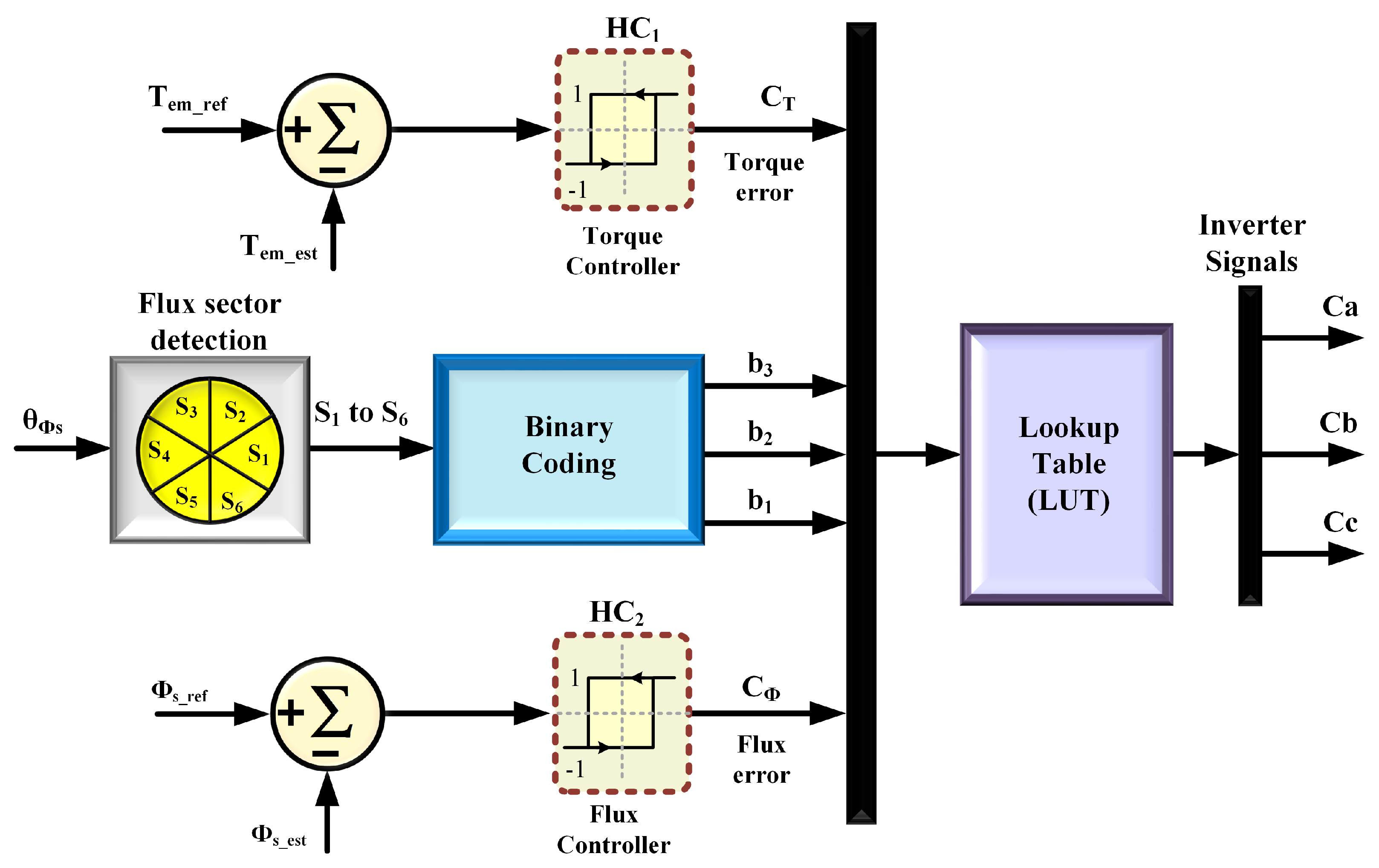
Figure 1. Block diagram of a conventional DTSFC algorithm.
Mathematics 10 03842 g001
Figure 2. The block diagram of the DRFOC algorithm of an induction motor.
Mathematics 10 03842 g002
Figure 3. The two block diagrams of the induction motor according to (a) α and (b) β axes.
Mathematics 10 03842 g003
Figure 4. (a) Control scheme of rotor flux for the α -axis. (b) Current controller for i s β component on the β -axis.
Mathematics 10 03842 g004
Figure 5. The proposed combined FOC-DTC algorithm.
Mathematics 10 03842 g005
Figure 6. Flowchart of the transition process in the proposed combined FOC-DTC algorithm.
Mathematics 10 03842 g006
Figure 7. The DTSFC with successive steps of torque references for testing stator and rotor flux responses.
Mathematics 10 03842 g007
Figure 8. The DTSFC algorithm with successive steps of the reference torque for testing torque response.
Mathematics 10 03842 g008
Figure 9. The DTSFC testbed for current response behaviour with increased torque reference.
Mathematics 10 03842 g009
Figure 10. The DTSFC testbed for speed response behaviour with increased torque reference.
Mathematics 10 03842 g010
Figure 11. The DTRFC with successive steps of torque reference for stator and rotor flux responses.
Mathematics 10 03842 g011
Figure 12. The DTRFC with successive steps of torque reference for testing torque response.
Mathematics 10 03842 g012
Figure 13. The DTRFC with successive steps of torque reference for current response.
Mathematics 10 03842 g013
Figure 14. The DTRFC with successive steps of torque reference for speed response.
Mathematics 10 03842 g014
Figure 15. The testbed behaviour of the FOC algorithm for rotor flux response.
Mathematics 10 03842 g015
Figure 16. The testbed behaviour of the FOC algorithm for torque response.
Mathematics 10 03842 g016
Figure 17. The testbed behaviour of the FOC algorithm for stator current vector components responses.
Mathematics 10 03842 g017
Figure 18. The testbed behaviour of the FOC algorithm three-phase current response.
Mathematics 10 03842 g018
Figure 19. The testbed behaviour of the FOC algorithm stator flux vector components responses.
Mathematics 10 03842 g019
Figure 20. The testbed behaviour of the FOC algorithm for rotor flux vector components responses.
Mathematics 10 03842 g020
Figure 21. Electromagnetic torque response of the proposed combined FOC-DTC algorithms.
Mathematics 10 03842 g021
Figure 22. Stator and rotor responses of the proposed combined FOC-DTC algorithm.
Mathematics 10 03842 g022
Figure 23. Three-phase currents of the proposed combined FOC-DTC algorithm.
Mathematics 10 03842 g023
Figure 24. Torque profile in the proposed combined FOC-DTC algorithm with different values of ( δ ) .
Mathematics 10 03842 g024
Figure 25. (a) Torque response of the proposed combined FOC-DTC algorithm for three values of K P ( β ) I . (b) Stator voltage vector modulus V s in the FOC algorithm.
Mathematics 10 03842 g025
Figure 26. Testbed behaviour of torque response within the transient state in the proposed FOC-DTC.
Mathematics 10 03842 g026
Figure 27. Torque response in the proposed combined FOC-DTC with different values of switch-on and -off.
Mathematics 10 03842 g027
Figure 28. Torque response in the proposed combined FOC-DTC with different values of switch-on and -off.
Mathematics 10 03842 g028
Figure 29. Torque response in the proposed FOC-DTC with different values of switch-on and -off.
Mathematics 10 03842 g029
Figure 30. Torque response in the proposed combined FOC-DTC over a wide torque range.
Mathematics 10 03842 g030
Figure 31. Stator and rotor fluxes responses in the proposed FOC-DTC over a wide torque range.
Mathematics 10 03842 g031
Figure 32. The experimental platform implemented to test the combined FOC-DTC scheme.
Mathematics 10 03842 g032
Figure 33. The performance of DTSFC with successive steps of the reference torque.
Mathematics 10 03842 g033
Figure 34. The performance of DTRFC with successive steps of the reference torque.
Mathematics 10 03842 g034
Figure 35. The performance of the proposed FOC-DTC at a speed value of 0.75 ω n .
Mathematics 10 03842 g035
Figure 36. The torque response in the combined FOC-DTC algorithm with different values of switch-on/off.
Mathematics 10 03842 g036
Figure 37. Comparisons of flux ripples for DTSFC, DTRFC, and the proposed FOC-DTC.
Mathematics 10 03842 g037
Figure 38. Comparisons of torque ripples for DTSFC, DTRFC, and the proposed FOC-DTC.
Mathematics 10 03842 g038
Figure 39. Comparisons of torque response in TSR for FOC, DTSFC, DTRFC, and the proposed FOC-DTC.
Mathematics 10 03842 g039
Table 1. Conventional switching table of the DTC algorithm.
Hysteresis LevelApplied Inverter Voltage Space Vectors
C F
C T
i = 1 V 5 V 6 V 3 V 2
i V i 2 V i 1 V i + 2 V i + 1
Table 2. Reference torque to test the combined algorithm over a wide range of torque operations.
Unit with TimeCommand Torque Sequence
Time (s)135789
T e m r e f (N.m)1.764.226−1.76−4.22−6
Table 3. Comparison between the proposed algorithm and previous and recent techniques.
Used MethodFlux RipplesTorque Response for (TSR)Torque Response for (SSR)High Torque Prod.Switching FrequencyOptional Gains
ProposedLower0.65 msLowerYesConstant2
Ref. [24]Low1 msLowYesConstant4
Ref. [25]High4 msHighNoVariable-
Ref. [26]No plot10 msLowNoVariableUnknown
Ref. [28]High1 msLowNoVariable-
Ref. [29]High10 msHighNoVariable-
Ref. [30]Low10 msLowNoConstant-
Ref. [31]High1 msHighNoVariable12
Ref. [34]Low16 msLowNoVariable2
Publisher’s Note: MDPI stays neutral with regard to jurisdictional claims in published maps and institutional affiliations.