Article

Improving Motor Imagery EEG Classification Based on Channel Selection Using a Deep Learning Architecture

by
Tat’y Mwata-Velu
1,
Juan Gabriel Avina-Cervantes
1,
Jose Ruiz-Pinales
1,
Tomas Alberto Garcia-Calva
1,
Erick-Alejandro González-Barbosa
2,
Juan B. Hurtado-Ramos
3 and
José-Joel González-Barbosa
3,*
1
Telematics and Digital Signal Processing Research Groups (CAs), Electronics Engineering Department, University of Guanajuato, Carr. Salamanca-Valle de Santiago km 3.5 + 1.8, Com. Palo Blanco, Salamanca 36885, Mexico
2
Tecnológico Nacional de México/ITS de Irapuato, Carretera Irapuato—Silao km 12.5 Colonia El Copal, Irapuato 36821, Mexico
3
Instituto Politécnico Nacional, Centro de Investigación en Ciencia Aplicada y Tecnología Avanzada—Unidad Querétaro, Av. Cerro Blanco 141, Col. Colinas del Cimatario, Querétaro 76090, Mexico
*
Author to whom correspondence should be addressed.
Mathematics 2022, 10(13), 2302; https://doi.org/10.3390/math10132302
Submission received: 26 May 2022 / Revised: 24 June 2022 / Accepted: 27 June 2022 / Published: 1 July 2022

Abstract

:
Recently, motor imagery EEG signals have been widely applied in Brain–Computer Interfaces (BCI). These signals are typically observed in the first motor cortex of the brain, resulting from the imagination of body limb movements. For non-invasive BCI systems, it is not apparent how to locate the electrodes, optimizing the accuracy for a given task. This study proposes a comparative analysis of channel signals exploiting the Deep Learning (DL) technique and a public dataset to locate the most discriminant channels. EEG channels are usually selected based on the function and nomenclature of electrode location from international standards. Instead, the most suitable configuration for a given paradigm must be determined by analyzing the proper selection of the channels. Therefore, an EEGNet network was implemented to classify signals from different channel location using the accuracy metric. Achieved results were then contrasted with results from the state-of-the-art. As a result, the proposed method improved BCI classification accuracy.

1. Introduction

Brain–computer interfaces (BCI) based on EEG signals have flooded scientific research and applications in recent years [1]. These BCI systems typically allow direct communication between a subject and a surrounding environment without muscle synergy movement and provide specific applications in various research fields. For example, BCIs have been used to diagnose cerebral diseases [2] and to propose patient treatment [3]. In addition, BCIs promise to improve the quality of life for many people [4]. Among BCI paradigms based on EEG signals, Motor Imagery (MI) signals take advantage of having direct social and medical impacts [5] by improving conditions of people who have lost motor skills, facilitating their independent communications with their surrounding environment [6]. Brain activity depends on the specific stimulus to which the subject under test is exposed. In particular, Electroencephalography records, invasively or non-invasively, the brain’s electromagnetic activity, i.e., neurons’ activity belonging to a specific area. Moreover, for visual stimulation, Bihan et al. [7] concluded that the visual cortex is activated in the same way as the mental representation of the same stimulus.
Innovative approaches have been proposed to solve the spatial resolution problem from non-invasive electroencephalography, increasing the number of active electrodes. These approaches intend to cover a larger cortical area obtaining relevant brain activity information [8]. However, for non-invasive BCI applications based on EEG signals, selecting appropriate electrodes for the targeted brain area is laborious if the equipment does not have built-in options to discriminate channels. For this reason, public EEG databases are developed considering all electrode channels, despite the prior knowledge of the brain zone activated by a specific stimulus.
The following practical challenges have arisen by increasing the number of electrodes for BCI systems:
1. Processing signals from inaccurate electrodes’ location: Basing exclusively on the electrode functions in the 10–20 or 10–10 international system [9] and neglecting the contribution of non-selected channels for a given task can lead to weak learning of signal features. Thus, there are less efficient results for the application.
2. Learning with noisy samples: Signals from passive electrodes, depending on the specific cognitive activity, are affected by noise, decreasing the performance of the suitable electrode channels. Therefore, signal processing can be computationally expensive and less efficient. In addition, Baig et al. [10] considered reducing the number of active electrodes between 10 and 30 without losing overall algorithmic performance [11].
3. Interference between signals from electrodes being too close together: Despite the precautions taken to control the electrode impedance and electromagnetic signal shielding features [12], another source of interference appears due to uncontrolled electrode closeness between them [13]. This challenge arises in practice with unconventional or low-tech systems.
Considerable research on EEG signals is still based on the 10–20 system proposed by the international federation for the electrodes placement [14], despite constructive criticism of its applicability on atypical skulls or specific cases [15], which also led to the variant 10–10 and 10–5 systems covering all the skull convexity by the electrodes and maximizing the cerebral activity measurements. Recently, motor imagery classification based on EEG channel selection has been developed to deduce the most discriminant channels implied in specific cognitive activities. Methods based on Common Spatial Pattern (CSP) and its variants flood the literature to maximize differences in variance between data labels. Yong et al. [16] reduced the number of electrodes by 11% on average from 118 electrodes, using a spatial filter based on CSP.
Conversely, Das and Suresh [11] applied a CSP variant and the effect-size based CSP (E-CSP) to eliminate channels that do not carry useful information, using Cohen’s based effect-size calculation. Likewise, efficient methods for electrode selection were explored using the Genetic Algorithm (GA) [17], mutual information [18], improved IterRelCen method built on the relief algorithm [19], and the modified Sequential Floating Forward Selection (SFFS) [20]. Additionally, one can gradually increase the number of electrodes to improve classification accuracy [21].
In summary, two effective ways to select the most discriminant electrode channels for a BCI system based on motor imagery EEG signals are: the measure built on electrode information and the criterion based on the classifier [10]. The first evaluates data properties like the distance between classes and probabilistic dependency [22]. The second type uses accuracy metric, error rate, Chi-squared, odds proportion, or probability ratio [23].
Although Table 1 specifies the specific brain area activated by a defined stimulus and Deecke’s and Neuper’s works locate imagined and executed limb movements on the somatosensory cortex [24,25], various authors experimented on the parallel activation of different brain areas caused by one or more stimuli [26,
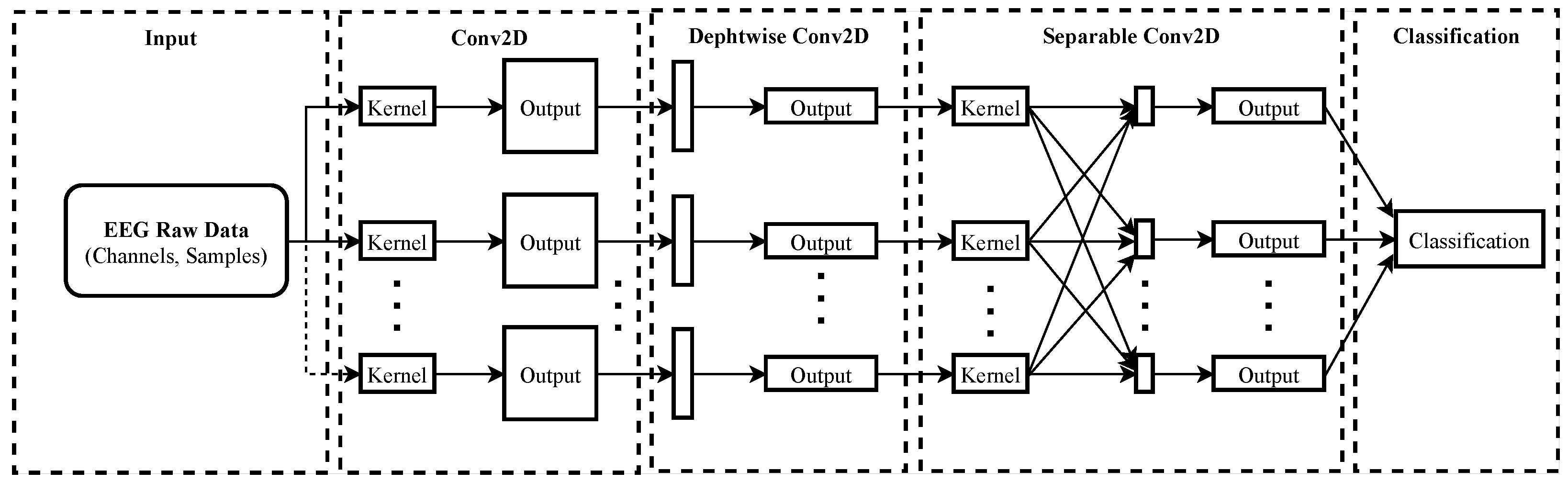
27]. Therefore, the hypothesis that other brain regions than the somatosensory cortex could be activated by fingers’ imagined movements is established in this paper. This work uses a classifier-based evaluation approach to select a discriminant channel subset maximizing the MI-EEG Signals classification using the EEGNet network [28]. This channel selection strategy is based on a software-level solution using the utility metric [29] to evaluate the influence of a group of channels on improving classification accuracy. A similar approach was developed by Narayanan and Bertrand in the auditory attention detection with the wireless EEG sensor network (WESN) [30], using the accuracy as the main outcome metric.
The public dataset proposed in [32], related to five-fingers MI-EEG signals, was used to analyze the channel contribution before building discriminant channel subsets. Secondly, the channel subset maximizing the classification accuracy using the EEGNet network is compared with channels suggested in the state-of-the-art. The main contributions of this study are summarized as follows:
  • A subset of discriminant electrode channels is more suitable for individual subject five-finger motor imagery classification.
  • A practical method to evaluate discriminant channel subsets for BCI systems is provided.
  • A cyclical learning rate is used in the EEGNet network to process the signal features efficiently and swiftly [33].
  • 4.
    In addition, the classification accuracy achieved by a compact DL technique is used as the BCI channel selection criterion.
    This paper is organized as follows: Section 2 presents the methods used in this work, including the EEG electrodes placement systems, the referred dataset, the proposed algorithm, and the neural network architecture. Then, in Section 3, the achieved results are discussed and evaluated, and, finally, the conclusions are given in Section 4.

    2. Methods

    The proposed approach aims to locate discriminant electrode channels for a given task using a public database and a compact convolutional neural network. Single signal and electrode combination accuracies are evaluated using the same parameters of the EEGNet network to deduce the discriminant electrode channels.

    2.1. Standardized Systems of EEG Electrodes Placement

    While numerous EEG capture equipment, standardized according to the international system 10–20 [9], use the craniocerebral topography illustrated in Figure 1a for electrodes placement, others benefit from the 10–10 norm presented in Figure 1b.
    The international 10–20 system provides 21 electrodes distributed proportionally on the scalp. The distance between two adjacent electrodes is 10 to 20% of the skull extremities’ total distance. The 10–10 standard [34] was developed with more electrodes (74). Table 1 explains the electrode function for each brain area. This work aims to determine the most discriminant electrode channels in terms of the accuracy metric.

    2.2. Referred Dataset

    The proposed method was evaluated on the public EEG dataset built by Kaya et al. [32], constituting five paradigms related to motor imagery. However, the present work uses paradigm #3 (5F) related to the right-hand fingers’ imagined movements (up or down flexion). Eight subjects (six men and two women) were trained to produce 36,800 independent samples of MI-EEG signals. EEG signals were captured with the Nihon Kohden-Japan EEG-1200 JE-921A medical equipment. The equipment consists of 19 electrodes organized according to the 10–20 International system and uses Neurofax recording software for playback and quantitative analysis of EEG data. In addition, experiment graphical user interfaces (eGUI) were designed in Matlab, helping test subjects to perform mental tasks. The experiment is summarized as follows: an experimental Graphical User Interface (eGUI) displays the right-hand fingers. When a number appears just above the finger, understood as the task start, the test subject imagines the flexion and extension movement of the corresponding finger for one second. The dataset holds thirteen files recorded at 1000 Hz (HFREQ) and six at 200 Hz (BFREQ). The recorded EEG signals are filtered internally at the hardware level by band-pass filters of 0.53–70 Hz for signals with a sampling frequency of 200 Hz and 0.53–100 Hz for those with a sampling frequency of 1000 Hz. In addition, the equipment integrates a notch filter at the hardware level, suitable at 50 Hz or 60 HZ depending on geographical areas of use, to reduce interference from the electrical grid.
    Technically limited by computational resources available for the algorithm test, this work presents only the results for signals at 200 Hz. Particularly, Kaya et al. [32] recommended the choice of the C3 channel for signal processing.

    2.3. Proposed Method

    The proposed method discriminates the active from the inactive electrode channels by classifying MI-EEG signals. Figure 2 presents the flowchart of the proposed method, which considers the public database, channel signal combinations, and the EEGNet network structure to deduce the best channel grouping based on classification accuracy. Therefore, the rating accuracy of classifying signals from channel combinations using the EEGNet network is considered to detect the stimulus-activated area. In this sense, Algorithm 1 seeks to find the subset of the most significant electrode channels maximizing the classification accuracy based on a given task. The first step consists of processing channel signals independently of those others. An electrode channel subset is constituted by selecting n channels with the best accuracies. Next, considering the number of electrodes maximizing the accuracy as a reference, combinations are made, progressively adding channels to the subset to obtain an accuracy equal to or greater than the reference accuracy. This latest varies according to the two, three, four, five, or six channels plus combinations. That is, the best classification accuracy of the 2-channel combination is taken as a reference to meet corresponding electrodes. In addition, this process is repeated for the 3-channel, 4-channel, and ith-channel combinations.
    Algorithm 1: Proposed algorithm for discriminant channel selection.
    Mathematics 10 02302 i001
    Finally, the most superior classification accuracy found with the ith-channel combination defines the nomenclature and, consequently, the spatial location of each electrode in the combination. The Gauss curve of accuracy depending on channel combination is expected with a maximum determining the number and nomenclature of discriminant channels. Let a = 2 i n , the number of channel combinations, and X i the accuracy corresponding to the ith-channel combination, that is,
    X i = f ( a ) ,
    and:
    N r = m a x ( X 2 , , X n ) ,
    where N r represents the number of recommended channels. In this work, only the increasing part of the accuracy curves will be reported to focus on the paper contribution.

    2.4. The EEGNet Model

    The EEGNet [28] is a CNN network whose robustness is proven by the number of related publications in BCI applications [35,36]. Such a network disposes of two convolution blocks: the first block comprises deep convolutions and the second block of separable convolutions. EEGNet uses temporal and spatial filters convolution to learn and produce separable features for the classifier, as illustrated in Figure 3.
    Whereas the matrix of the data read from the database is presented as:
    E E G r a w = ( n u m _ s a m p l e s , s a m p l e _ l e n g t h , C h a n n e l ) ,
    for the EEGNet input, that matrix is rearranged as (4),
    E E G r a w = ( n u m _ s a m p l e s , C h a n n e l , s a m p l e _ l e n g t h , 1 ) ,
    where num_samples is the number of samples and sample_length is the sequence length of the raw EEG signals. The depthwise convolution layer predicts an in-depth model based on the number of parameters, notably using a temporal and spatial filter bank. The separable conv2D layer temporally separates individual feature maps and optimizes the output before the classification step, where the Softmax activation function is applied.
    This work sets temporal and spatial filters at 8, kernel length at 3, and regularization dropout rate at 0.2. The built model was fitted with 2000 epochs, using the Nesterov-accelerated Adaptive Moment Estimation (NADAM) optimizer and a batch size of 330. This network parameters configuration is typically based on settings adjusted in [37], where another channel selection criterion was used. This is to evaluate the contribution of this paper making comparison. The cyclical learning rate [33] was implemented in this project to accelerate features learning, and the EEGNet network benefits from separating features with few training data. A triangular window was adopted, varying the learning rate between 10 5 and 5 × 10 3 , with a gamma value of 0.998. The model was built in Keras and Tensorflow with parameters illustrated in Table 2 and executed on a 64-bit A l i e n w a r e 14 laptop computer with dual GeForce GTX 765M GPUs under Linux. The 200-fold cross-validation method was used to support the results. Finally, Table 3 summarizes the hyper-parameters values set for the data training with the EEGNet model.

    3. Results and Discussion

    The first stage of the proposed algorithm consists of processing each electrode channel independently of the others, to group as many electrodes as possible and, therefore, to maximize the accuracy. Table 4 presents the results achieved by processing the 19 electrode channels. The top-6 accuracies achieved for each individual subject are indicated in boldface, where the best accuracy is highlighted in blue.
    Next, six channels corresponding to the top-6 accuracies were selected to constitute the electrode channel subset for the next algorithm stage. This number of electrodes was chosen accordingly after extensive testing with all channels’ combination, beginning from channels offering two best accuracies per subject and increasing this grouping for three, four, five, and for all best accuracies per subject. Thereby, accuracy curves remained to ascend while more channels were added until the six-channel combination before decreasing.
    For s u b j e c t A , the highest accuracy was 86.6%, using the F7 channel corresponding to the frontal brain region, curiously dedicated to verbal expression. Therefore, channels Fp1, Fp2, F3, F8, and T5, corresponding to the following top-5 accuracies, are selected to form 2-channel combinations with the F7 channel for the following step. The same procedure was carried out for individual s u b j e c t s B , C and F. For instance, the top-6 accuracies for s u b j e c t B correspond to T6, P4, P3, Cz, O1, and T5 channels. Therefore, channels P4, P3, Cz, O1, and T5 are selected to form 2-channel combinations with the T6 channel for the following step. Table 5 shows the results for the different 2-channel combinations for each subject. It can be observed that the highest classification accuracies are now 90.5%, 81.5%, 82.9%, and 76.6% for s u b j e c t s A , B , C , and F, respectively.
    For s u b j e c t A , the best results are obtained using channels {F7, Fp2} which correspond to the frontal region. Likewise, for s u b j e c t F , the best results are obtained using channels {O1, O2} corresponding to the occipital brain region, precisely related to visual processing. Contrariwise, for s u b j e c t s B and C, the best results were obtained for {T6, O1} and {C4, P3}, respectively, corresponding to different brain regions, temporal-occipital for s u b j e c t B and central-parietal for s u b j e c t C .
    Hence, {F7, Fp2}, {T6, O1}, {C4, P3}, and {O1, O2} combinations are used to form 3-channel combinations with the remaining channels ({Fp1, F8, F3, T5}, {T5, Cz, P3, P4}, {F8, T5, O1, T6} and {T5, P3, C3, P4}), for the next step. Table 6 presents classification accuracies achieved for each 3-channel combination and subject. s u b j e c t A achieved the highest accuracy of 90.8% with {F7, Fp2, T5} channel combination signals, s u b j e c t B an accuracy of 83.8% with signals from {T6, O1, Cz} channels combination. With {C4, P3, T6} channel combination signals, s u b j e c t C achieved an accuracy of 85.6%, while an accuracy of 79.3% was found with {O1, O2, P3} channel combination signals of s u b j e c t F . Therefore, those electrode channel combinations are used to form 4-channel combinations for the next step.
    Table 7 presents the results for each 4-channel combination and subject. The highest accuracies are now 91.7%, 85.1%, 88.5%, and 80.1% for s u b j e c t s A , B, C, and F, respectively.
    Table 8 shows the results for each 5-channel combination and subject. The highest accuracies change now to 92.8%, 86.3%, 88.6%, and 80.8% for s u b j e c t s A , B, C and F, respectively.
    Table 9 presents the results for 6-channel combinations. The best accuracies are 93.1%, 87.2%, 90.3%, and 81.0% for subjects A, B, C, and F, respectively.
    Figure 4 shows the classification accuracies as a function of the number of channels. Beyond six channels, the curves begin to decrease.
    Table 10 presents the gain in classification accuracy by adding selective channels according to Algorithm 1. For s u b j e c t s B and F, the best accuracy was obtained for channels {T6, O1, Cz, P4, P3, T5} and {O1, O2, P3, C3, T5, P4}.
    For s u b j e c t C , the best accuracy was achieved using channels {C4, P3, T6, T5, O1, F8}.
    By methodically adding channels according to Algorithm 1, the evolution of the classification accuracy reaches a maximum that defines the optimal number of channels.
    Figure 5 illustrates the discriminant channel subsets obtained by using the proposed algorithm. As established in the hypothesis, the parietal, temporal, visual, and motor cerebral cortices are stimulated by imaginary finger movements depending on the test subject. S u b j e c t A performs a classification accuracy with the frontal and parietal cortices activated. For s u b j e c t s B and F, the parietal, motor, and temporal cerebral cortices are activated against the stimulation of all cortices for s u b j e c t C . Each increase in the number of channels generates an accuracy gain, see Table 10.
    Table 11 summarizes the optimal channel combinations depending on the desired number of channels.
    Table 12 compares the results achieved using the proposed algorithm and other state-of-the-art approaches [37,38], where signals from the {C3, Cz, P3, Pz} channel subset or all channels were selected to be processed. In such studies, raw EEG signals were preprocessed using the Empirical Mode Decomposition (EMD) and Common Spatial Pattern (CSP) methods. In [39], Alomari et al. selected {C3, C4, Cz} EEG channel subset to discriminate right-left imagined and executed fists movements based on Deecke’s and Neuper’s works [24,25]. Similarly, O1 and O2 electrodes were evaluated as discriminant by Zhou et al. [40], in the implementation of a driving car brain–computer interfaces, using EEG signals of visual-motor imagery preprocessed by the Hilbert–Huang Transform. The results obtained in this work satisfactorily prove a classification accuracy improvement compared to the state-of-the-art, which uses wrong or all electrodes, as shown in Table 12.

    4. Conclusions

    The present work aimed to find discriminant channels using a DL approach. To accurately perform the imagined flexion-extension task of the right-hand fingers, whose EEG data are provided by a public dataset, the compact convolutional neural network for EEG-based brain–computer interfaces (EEGNet) was implemented. The search for discriminating channels was based on the inverse problem by determining the combination of electrodes that maximizes the classification accuracy. The results encountered explain the activation of various cerebral cortices depending on the test subject, despite the standard conditions defined in the paradigm (mental task, signal length, capture conditions). S u b j e c t A (93.1%) achieved the highest classification rates, followed by s u b j e c t C (90.3%). The lowest classification accuracy was obtained for s u b j e c t F , delivering 81.0%. Such an approach provides an average classification accuracy gain of 8.6% by increasing the number of channels from one to six. Therefore, whatever the standard used for capturing EEG signals, selecting channels for a BCI system whose EEG data are provided from more than one subject must consider the discriminating electrodes, the nomenclature of which may differ from one test subject to another. The outstanding contribution of this work proposes a practical channel selection method based on deep learning for EEG-BCI systems and provides better classification accuracy with the tested dataset. As future work, an embedded EEG-BCI based on fingers’ motor imagery signals is projected. The finger movements of a hand prosthesis will be controlled in real-time by an EMOTIV EPOC headset and a Jetson Nano development board. Hence, the results achieved in this work will serve as a comparison for the further step.

    Author Contributions

    Conceptualization, T.M.-V.; data curation, J.B.H.-R. and J.-J.G.-B.; formal analysis, J.B.H.-R., J.G.A.-C. and T.A.G.-C.; funding acquisition, J.-J.G.-B. and J.B.H.-R.; investigation, T.M.-V., J.R.-P., J.-J.G.-B. and J.G.A.-C.; methodology, J.R.-P. and J.G.A.-C.; software, T.M.-V., J.B.H.-R. and J.G.A.-C.; validation, J.R.-P., T.A.G.-C. and J.G.A.-C.; writing—original draft, T.M.-V. and E.-A.G.-B.; writing—review and editing, J.R.-P., E.-A.G.-B. and J.G.A.-C. All authors read and agreed to the published version of the manuscript.

    Funding

    This project was funded by the Mexican National Council of Science and Technology CONACyT, under Grant No. 763527 and the University of Guanajuato Grant No. 171/2022. Instituto Politécnico Nacional Grant Number SIP-20220644.

    Institutional Review Board Statement

    Ethical review and approval are waived for this kind of study.

    Informed Consent Statement

    No formal written consent was required for this study.

    Data Availability Statement

    Data available upon formal demand.

    Conflicts of Interest

    The authors declare that they have no conflict of interest. The funders had no role in the design of the study; in the collection, analyses, or interpretation of data; in the writing of the manuscript, or in the decision to publish the results.

    References

    1. Chamola, V.; Vineet, A.; Nayyar, A.; Hossain, E. Brain-Computer Interface-Based Humanoid Control: A Review. Sensors 2020, 20, 3620. [Google Scholar] [CrossRef] [PubMed]
    2. Wen, D.; Jia, P.; Lian, Q.; Zhou, Y.; Lu, C. Review of Sparse Representation-Based Classification Methods on EEG Signal Processing for Epilepsy Detection, Brain-Computer Interface and Cognitive Impairment. Front. Aging Neurosci. 2016, 8, 172. [Google Scholar] [CrossRef] [PubMed]
    3. Cervera, M.; Soekadar, S.; Ushiba, J.; Millan, J.d.R.; Liu, M.; Birbaumer, N.; Gangadhar, G. Brain-computer interfaces for post-stroke motor rehabilitation: A meta-analysis. Ann. Clin. Transl. Neurol. 2018, 5, 651–663. [Google Scholar] [CrossRef] [PubMed]
    4. Kobayashi, N.; Nakagawa, M. BCI-based control of electric wheelchair using fractal characteristics of EEG. IEEJ Trans. Electr. Electron. Eng. 2018, 13, 1795–1803. [Google Scholar] [CrossRef]
    5. Onose, G.; Grozea, C.; Anghelescu, A.; Daia, C.; Sinescu, C.; Ciurea, A.; Spircu, T.; Andone, I.; Spanu, A.; Popescu, C.; et al. On the feasibility of using motor imagery EEG-based brain-computer interface in chronic tetraplegics for assistive robotic arm control: A clinical test and long-term post-trial follow-up. Spinal Cord 2012, 50, 599–608. [Google Scholar] [CrossRef] [PubMed] [Green Version]
    6. Salguero, J.; Avilás Sánchez, O.; Mauledoux, M. Design of a Personal Communication Device, Based in EEG Signals. Int. J. Commun. Antenna Propag. (IRECAP) 2017, 7, 88. [Google Scholar] [CrossRef]
    7. Bihan, D.; Turner, R.; Zeffiro, T.; Cuenod, C.; Jezzard, P.; Bonnerot, V. Activation of human primary visual cortex during visual recall: A magnetic resonance imaging study. Proc. Natl. Acad. Sci. USA 1994, 90, 11802–11805. [Google Scholar] [CrossRef] [Green Version]
    8. Ganguly, S.; Singla, R. Electrode channel selection for emotion recognition based on EEG signal. In Proceedings of the 2019 IEEE 5th International Conference for Convergence in Technology (I2CT), Bombay, India, 29–31 March 2019; pp. 1–4. [Google Scholar] [CrossRef]
    9. Klem, G.; Lüders, H.; Jasper, H.; Elger, C. The ten-twenty electrode system of the International Federation. The International Federation of Clinical Neurophysiology. Electroencephalogr. Clin. Neurophysiol. 1999, 52, 3–6. [Google Scholar]
    10. Baig, M.Z.; Aslam, N.; Shum, H. Filtering techniques for channel selection in motor imagery EEG applications: A survey. Artif. Intell. Rev. 2020, 53, 1207–1232. [Google Scholar] [CrossRef] [Green Version]
    11. Das, A.; Suresh, S. An Effect-Size Based Channel Selection Algorithm for Mental Task Classification in Brain Computer Interface. In Proceedings of the 2015 IEEE International Conference on Systems, Man, and Cybernetics, Hong Kong, China, 9–12 October 2015; pp. 3140–3145. [Google Scholar] [CrossRef]
    12. Lin, C.T.; Liu, C.H.; Wang, P.S.; King, J.T.; Liao, L.D. Design and Verification of a Dry Sensor-Based Multi-Channel Digital Active Circuit for Human Brain Electroencephalography Signal Acquisition Systems. Micromachines 2019, 10, 720. [Google Scholar] [CrossRef] [Green Version]
    13. Wang, Y.; Xu, G.; Zhang, S.; Luo, A.; Li, M.; Han, C. EEG signal co-channel interference suppression based on image dimensionality reduction and permutation entropy. Signal Process. 2017, 134, 113–122. [Google Scholar] [CrossRef]
    14. Homan, R.; Herman, J.; Purdy, P. Cerebral location of International 10-20 system electrode placement. Electroencephalogr. Clin. Neurophysiol. 1987, 66, 376–382. [Google Scholar] [CrossRef]
    15. Oostenveld, R.; Praamstra, P. The five percent electrode system for high-resolution EEG and ERP measurements. Clin. Neurophysiol. Off. J. Int. Fed. Clin. Neurophysiol. 2001, 112, 713–719. [Google Scholar] [CrossRef]
    16. Yong, X.; Ward, R.; Birch, G. Sparse spatial filter optimization for EEG channel reduction in brain-computer interface. In Proceedings of the ICASSP, IEEE International Conference on Acoustics, Speech and Signal Processing, Las Vegas, NV, USA, 31 March–4 April 2008; pp. 417–420. [Google Scholar] [CrossRef]
    17. He, L.; Hu, Y.; Li, Y.; Li, D. Channel selection by Rayleigh coefficient maximization based genetic algorithm for classifying single-trial motor imagery EEG. Neurocomputing 2013, 121, 423–433. [Google Scholar] [CrossRef]
    18. Yang, H.; Guan, C.; Wang, C.; Ang, K. Maximum dependency and minimum redundancy-based channel selection for motor imagery of walking EEG signal detection. In Proceedings of the Acoustics, Speech, and Signal Processing (ICASSP-88, 1988), Vancouver, BC, Canada, 26–31 May 2013; pp. 1187–1191. [Google Scholar] [CrossRef]
    19. Shan, H.; Xu, H.; Zhu, S.; He, B. A novel channel selection method for optimal classification in different motor imagery BCI paradigms. BioMed. Eng. Online 2015, 14, 93. [Google Scholar] [CrossRef] [Green Version]
    20. Qiu, Z.; Jin, J.; Lam, H.K.; Zhang, Y.; Wang, X.; Cichocki, A. Improved SFFS method for channel selection in motor imagery based BCI. Neurocomputing 2016, 207, 519–527. [Google Scholar] [CrossRef] [Green Version]
    21. Shan, H.; Yuan, H.; Zhu, S.; He, B. EEG-based motor imagery classification accuracy improves with gradually increased channel number. In Proceedings of the 2012 Annual International Conference of the IEEE Engineering in Medicine and Biology Society, San Diego, CA, USA, 28 August–1 September 2012; pp. 1695–1698. [Google Scholar] [CrossRef]
    22. Lazar, C.; Taminau, J.; Meganck, S.; Steenhoff, D.; Coletta, A.; Molter, C.; de Schaetzen, V.; Duque, R.; Bersini, H.; Nowe, A. A Survey on Filter Techniques for Feature Selection in Gene Expression Microarray Analysis. IEEE/ACM Trans. Comput. Biol. Bioinform. 2012, 9, 1106–1119. [Google Scholar] [CrossRef]
    23. Sen, B.; Peker, M.; Cav, A.; Celebi, F. A Comparative Study on Classification of Sleep Stage Based on EEG Signals Using Feature Selection and Classification Algorithms. J. Med. Syst. 2014, 38, 18. [Google Scholar] [CrossRef]
    24. Deecke, L.; Weinberg, H.; Brickett, P. Magnetic fields of the human brain accompanying voluntary movement: Bereitschaftsmagnetfeld. Exp. Brain Res. Exp. Hirnforsch. Exp. Cerebrale 1982, 48, 144–148. [Google Scholar] [CrossRef]
    25. Neuper, C.; Pfurtscheller, G. Evidence for distinct beta resonance frequencies in human EEG related to specific cortical areas. Clin. Neurophysiol. Off. J. Int. Fed. Clin. Neurophysiol. 2001, 112, 2084–2097. [Google Scholar] [CrossRef]
    26. Ganis, G.; Thompson, W.L.; Kosslyn, S.M. Brain areas underlying visual mental imagery and visual perception: An fMRI study. Cogn. Brain Res. 2004, 20, 226–241. [Google Scholar] [CrossRef] [PubMed]
    27. Hermes, D.; Vansteensel, M.J.; Albers, A.M.; Bleichner, M.G.; Benedictus, M.R.; Orellana, C.M.; Aarnoutse, E.J.; Ramsey, N.F. Functional MRI-based identification of brain areas involved in motor imagery for implantable brain–computer interfaces. J. Neural Eng. 2011, 8, 025007. [Google Scholar] [CrossRef] [PubMed]
    28. Lawhern, V.J.; Solon, A.J.; Waytowich, N.R.; Gordon, S.M.; Hung, C.P.; Lance, B.J. EEGNet: A compact convolutional neural network for EEG-based brain–computer interfaces. J. Neural Eng. 2018, 15, 056013. [Google Scholar] [CrossRef] [PubMed] [Green Version]
    29. Bertrand, A. Utility Metrics for Assessment and Subset Selection of Input Variables for Linear Estimation [Tips & Tricks]. IEEE Signal Process. Mag. 2018, 35, 93–99. [Google Scholar] [CrossRef]
    30. Narayanan, A.M.; Bertrand, A. Analysis of Miniaturization Effects and Channel Selection Strategies for EEG Sensor Networks with Application to Auditory Attention Detection. IEEE Trans. Biomed. Eng. 2020, 67, 234–244. [Google Scholar] [CrossRef]
    31. Syakiylla, S.; Syakiylla Sayed Daud, S.; Sudirman, R. Decomposition Level Comparison of Stationary Wavelet Transform Filter for Visual Task Electroencephalogram. J. Teknol. 2015, 74, 7–13. [Google Scholar] [CrossRef] [Green Version]
    32. Kaya, M.; Binli, M.; Ozbay, E.; Yanar, H.; Mishchenko, Y. A large electroencephalographic motor imagery dataset for electroencephalographic brain computer interfaces. Sci. Data 2018, 5, 180211. [Google Scholar] [CrossRef] [Green Version]
    33. Smith, L.N. Cyclical learning rates for training neural networks. In Proceedings of the 2017 IEEE Winter Conference on Applications of Computer Vision (WACV), Santa Rosa, CA, USA, 24–31 March 2017; pp. 464–472. [Google Scholar] [CrossRef] [Green Version]
    34. Chatrian, G.E.; Lettich, E.; Nelson, P. Modified Nomenclature for the “10%” Electrode System. J. Clin. Neurophysiol. Off. Publ. Am. Electroencephalogr. Soc. 1988, 5, 183–186. [Google Scholar] [CrossRef]
    35. Waytowich, N.; Lawhern, V.J.; Garcia, J.O.; Cummings, J.; Faller, J.; Sajda, P.; Vettel, J.M. Compact convolutional neural networks for classification of asynchronous steady-state visual evoked potentials. J. Neural Eng. 2018, 15, 066031. [Google Scholar] [CrossRef]
    36. Shoji, T.; Yoshida, N.; Tanaka, T. Automated detection of abnormalities from an EEG recording of epilepsy patients with a compact convolutional neural network. Biomed. Signal Process. Control. 2021, 70, 103013. [Google Scholar] [CrossRef]
    37. Mwata-Velu, T.; Avina-Cervantes, J.G.; Cruz-Duarte, J.M.; Rostro-Gonzalez, H.; Ruiz-Pinales, J. Imaginary Finger Movements Decoding Using Empirical Mode Decomposition and a Stacked BiLSTM Architecture. Mathematics 2021, 9, 3297. [Google Scholar] [CrossRef]
    38. Anam, K.; Bukhori, S.; Hanggara, F.; Pratama, M. Subject-independent classification on brain-computer interface using autonomous deep learning for finger movement recognition. In Proceedings of the 42nd Annual International Conference of the IEEE Engineering in Medicine Biology Society (EMBC), Montreal, QC, Canada, 20–24 July 2020; pp. 447–450. [Google Scholar] [CrossRef]
    39. Alomari, M.; Awada, E.; Younis, O. Subject-Independent EEG-Based Discrimination Between Imagined and Executed, Right and Left Fists Movements. Eur. J. Sci. Res. 2014, 118, 364–373. [Google Scholar]
    40. Zhou, Z.; Gong, A.; Qian, Q.; Su, L.; Zhao, L.; Fu, Y. A novel strategy for driving car brain-computer interfaces: Discrimination of EEG-based visual-motor imagery. Transl. Neurosci. 2021, 12, 482–493. [Google Scholar] [CrossRef] [PubMed]
    Figure 1. The spatial location of electrodes according to standard systems. Each electrode is located by a letter and a number. The letter expresses the brain cortex for the electrode location: frontal (F), central (C), parietal (P), Occipital (O), temporal (T), and frontoparietal (FP). Even numbers are used for the brain’s right hemisphere, while odd numbers are for the brain’s left hemisphere. (a) the 10–20 International system; (b) the 10–10 International System.
    Figure 1. The spatial location of electrodes according to standard systems. Each electrode is located by a letter and a number. The letter expresses the brain cortex for the electrode location: frontal (F), central (C), parietal (P), Occipital (O), temporal (T), and frontoparietal (FP). Even numbers are used for the brain’s right hemisphere, while odd numbers are for the brain’s left hemisphere. (a) the 10–20 International system; (b) the 10–10 International System.
    Mathematics 10 02302 g001
    Figure 2. Overview of the proposed method. Each channel Data-stream ( F P 1 , F P 2 , , O 2 ) and their combinations are processed using the EEGNet network to classify five fingers’ imagined movements. Next, the best test accuracies found from signals classification are used to locate the respective channels.
    Figure 2. Overview of the proposed method. Each channel Data-stream ( F P 1 , F P 2 , , O 2 ) and their combinations are processed using the EEGNet network to classify five fingers’ imagined movements. Next, the best test accuracies found from signals classification are used to locate the respective channels.
    Mathematics 10 02302 g002
    Figure 3. The EEGNet network structure. As a typical CNN, the EEGNet structure additionally disposes of depth-wise and separable convolution layers, allowing features separation for the signal classification stage.
    Figure 3. The EEGNet network structure. As a typical CNN, the EEGNet structure additionally disposes of depth-wise and separable convolution layers, allowing features separation for the signal classification stage.
    Mathematics 10 02302 g003
    Figure 4. Accuracy as a function of the number of channels per subject.
    Figure 4. Accuracy as a function of the number of channels per subject.
    Mathematics 10 02302 g004
    Figure 5. Spatial maps of discriminant channel subsets for individual s u b j e c t s A , B , C , and F. (a) s u b j e c t A ; (b) s u b j e c t B ; (c) s u b j e c t C ; (d) s u b j e c t F .
    Figure 5. Spatial maps of discriminant channel subsets for individual s u b j e c t s A , B , C , and F. (a) s u b j e c t A ; (b) s u b j e c t B ; (c) s u b j e c t C ; (d) s u b j e c t F .
    Mathematics 10 02302 g005
    Table 1. Nomenclature and functions for the electrodes in the international 10–20 system, Syakiylla et al. [31].
    Table 1. Nomenclature and functions for the electrodes in the international 10–20 system, Syakiylla et al. [31].
    Brain RegionElectrode Function
    FrontalFp1Attention
    Fp2Judgment restrains impulses
    F7Verbal expression
    F3Motor planning
    F4Motor planning of left-upper extremity
    F8Emotional expression
    TemporalT3Verbal memory
    T4Emotional memory
    T5Verbal understanding
    T6Emotional understanding and motivation
    CentralC3Sensorimotor integration (right)
    CzSensorimotor integration (midline)
    C4Sensorimotor integration (left)
    ParietalP3Cognitive processing special temporal
    PzCognitive processing
    P4“Math word problems”, “Non-verbal reasoning”
    OccipitalO1Visual processing
    OzIncontinence
    O2Visual processing
    Table 2. Number of parameters for the implemented EEGNet receiving k channels.
    Table 2. Number of parameters for the implemented EEGNet receiving k channels.
    Layer (Type)Output ShapeParameters
    InputLayer(None, k, 170, 1)0
    Conv2D(None, k, 170, 8)64
    Batch_normalization_1(None, k, 170, 8)32
    Depthwise_conv2D(None, 1, 170, 64)64 × k
    Batch_normalization_2(None, 1, 170, 64)256
    Activation_1(None, 1, 170, 64)0
    Average_pooling2D_1(None, 1, 42, 64)0
    Dropout_1(None, 1, 42, 64)0
    Separable_conv2D(None, 1, 42, 64)5120
    Batch_normalization_3(None, 1, 42, 64)256
    Activation_2(None, 1, 42, 64)0
    Average_pooling2D_2(None, 1, 5, 64)0
    Dropout_2(None, 1, 5, 64)0
    Flatten(None, 320)0
    Dense(None, 5)1605
    Softmax(None, 5)0
    Table 3. The summary of configured hyper-parameters for the EEGNet’ model training.
    Table 3. The summary of configured hyper-parameters for the EEGNet’ model training.
    Hyper-ParameterValues Set
    Epochs number2000
    OptimizerNadam (0.001)
    Loss functionCategorical cross-entropy
    MetricAccuracy
    Batch size330
    Table 4. Classification accuracies achieved for each electrode channel.
    Table 4. Classification accuracies achieved for each electrode channel.
    ElectrodeAccuracies (%)
    Subject ASubject BSubject CSubject F
    Fp183.572.372.262.3
    Fp284.572.473.362.2
    F786.669.075.160.4
    F380.669.168.762.9
    Fz65.767.868.560.3
    F478.870.870.964.4
    F883.874.478.263.1
    T368.268.873.564.9
    C372.471.674.566.8
    Cz69.575.274.060.8
    C471.874.681.464.1
    T475.572.373.462.1
    T584.574.775.868.1
    P370.375.279.067.0
    Pz70.971.071.865.8
    P472.677.671.868.0
    T672.778.975.363.6
    O168.475.075.670.2
    O272.474.073.866.2
    Table 5. Classification accuracies achieved for each 2-channel combination.
    Table 5. Classification accuracies achieved for each 2-channel combination.
    SubjectCombinationAcc. (%)
    F7 - Fp187.0
    F7 - Fp290.5
    AF7 - F384.1
    F7 - F886.5
    F7 - T586.4
    T6 - P476.7
    T6 - P379.6
    BT6 - Cz76.3
    T6 - O181.5
    T6 - T580.0
    C4 - F881.5
    C4 - P382.9
    CC4 - T581.3
    C4 - O181.8
    C4 - T682.7
    O1 - O276.6
    O1 - T573.2
    FO1 - P371.1
    O1 - C370.7
    O1 - P472.4
    Table 6. Classification accuracies achieved for each 3-channel combination.
    Table 6. Classification accuracies achieved for each 3-channel combination.
    SubjectCombinationAcc. (%)
    F7 - Fp2 - Fp188.4
    AF7 - Fp2 - F889.5
    F7 - Fp2 - F389.4
    F7 - Fp2 - T590.8
    T6 - O1 -T583.0
    BT6 - O1 - Cz83.8
    T6 - O1 - P382.2
    T6 - O1 - P482.6
    C4 - P3 - F884.8
    CC4 - P3 - T583.9
    C4 - P3 - O183.7
    C4 - P3 - T685.6
    O1 - O2 - T577.5
    FO1 - O2 - P379.3
    O1 - O2 - C377.1
    O1 - O2 - P478.2
    Table 7. Classification accuracies achieved for each 4-channel combination.
    Table 7. Classification accuracies achieved for each 4-channel combination.
    SubjectCombinationAcc. (%)
    F7 - Fp2 - T5 - Fp190.6
    AF7 - Fp2 - T5 - F891.0
    F7 - Fp2 - T5 - F391.7
    T6 - O1 - Cz - T584.7
    BT6 - O1 - Cz - P384.3
    T6 - O1 - Cz - P485.1
    C4 - P3 - T6 - O186.4
    CC4 - P3 - T6 - T588.5
    C4 - P3 - T6 - F887.5
    O1 - O2 - P3 - T578.6
    FO1 - O2 - P3 - C380.1
    O1 - O2 - P3 - P479.0
    Table 8. Classification accuracies achieved for each 5-channel combination.
    Table 8. Classification accuracies achieved for each 5-channel combination.
    SubjectCombinationAcc. (%)
    AF7 - Fp2 - T5 - F3 - F8 92.8
    F7 - Fp2 - T5 - F3 - Fp192.2
    BT6 - O1 - Cz - P4 - T585.2
    T6 - O1 - Cz - P4 - P386.3
    CC4 - P3 - T6 - T5 - O188.6
    C4 - P3 - T6 - T5 - F888.1
    FO1 - O2 - P3 - C3 - T580.8
    O1 - O2 - P3 - C3 - P479.4
    Table 9. Classification accuracies achieved for each 6-channel combination.
    Table 9. Classification accuracies achieved for each 6-channel combination.
    SubjectChannels CombinationAcc. (%)
    AF7 - Fp2 - T5 - F3 - F8 - Fp193.1
    BT6 - O1 - Cz - P4 - P3 - T587.2
    CC4 - P3 - T6 - T5 - O1 - F890.3
    FO1 - O2 - P3 - C3 - T5 - P481.0
    Table 10. Classification accuracy gain achieved after adding channels for each subject.
    Table 10. Classification accuracy gain achieved after adding channels for each subject.
    SubjectHeadway of Adding ChannelsGain
    1 → 22 → 33 → 44 → 55 → 6
    A3.90.30.91.10.31.3
    B2.62.31.31.20.91.6
    C1.52.72.90.11.71.7
    F6.42.70.80.70.22.1
    Rel. Gain3.62.01.40.70.71.6
    Table 11. Summary of the optimal channel combinations.
    Table 11. Summary of the optimal channel combinations.
    SubjectNumber of Channels
    123456
    A{F7}{F7,Fp2}{F7,Fp2,T5}{F7,Fp2,T5,F3}{F7,Fp2,T5,F3,F8}{F7,Fp2,T5,F3,F8,Fp1}
    B{T6}{T6,O1}{T6,O1,Cz}{T6,O1,Cz,P4}{T6,O1,Cz,P4,P3}{T6,O1,Cz,P4,P3,T5}
    C{C4}{C4,P3}{C4,P3,T6}{C4,P3,T6,T5}{C4,P3,T6,T5,O1}{C4,P3,T6,T5,O1,F8}
    F{O1}{O1,O2}{O1,O2,P3}{O1,O2,P3,C3}{O1,O2,P3,C3,T5}{O1,O2,P3,C3,T5,P4}
    Table 12. Comparison with the state-of-the-art based on other channel selection approaches.
    Table 12. Comparison with the state-of-the-art based on other channel selection approaches.
    SubjectItemsMethods
    EMD+EEGNet [37]ADL Network [38]Proposed Method
    AChannels{C3,Cz,P3,Pz}All{F7,Fp2,T5,F3}
    No. of channels4194
    No. of samples497449744974
    Accuracy81.8%77.4%91.7%
    BChannels{C3,Cz,P3,Pz}All{T6,O1,Cz,P4}
    No. of channels4194
    No. of samples495949594959
    Accuracy75.2%77.8%85.1%
    CChannels{C3,Cz,P3,Pz}All{C4,P3,T6,T5}
    No. of channels4194
    No. of samples594159415941
    Accuracy82.2%81.6%88.5%
    FChannels{C3,Cz,P3,Pz}All{O1,O2,P3,C3}
    No. of channels4194
    No. of samples494749474947
    Accuracy79.7%78.1%80.1%
    Publisher’s Note: MDPI stays neutral with regard to jurisdictional claims in published maps and institutional affiliations.

    Share and Cite

    MDPI and ACS Style

    Mwata-Velu, T.; Avina-Cervantes, J.G.; Ruiz-Pinales, J.; Garcia-Calva, T.A.; González-Barbosa, E.-A.; Hurtado-Ramos, J.B.; González-Barbosa, J.-J. Improving Motor Imagery EEG Classification Based on Channel Selection Using a Deep Learning Architecture. Mathematics 2022, 10, 2302. https://doi.org/10.3390/math10132302

    AMA Style

    Mwata-Velu T, Avina-Cervantes JG, Ruiz-Pinales J, Garcia-Calva TA, González-Barbosa E-A, Hurtado-Ramos JB, González-Barbosa J-J. Improving Motor Imagery EEG Classification Based on Channel Selection Using a Deep Learning Architecture. Mathematics. 2022; 10(13):2302. https://doi.org/10.3390/math10132302

    Chicago/Turabian Style

    Mwata-Velu, Tat’y, Juan Gabriel Avina-Cervantes, Jose Ruiz-Pinales, Tomas Alberto Garcia-Calva, Erick-Alejandro González-Barbosa, Juan B. Hurtado-Ramos, and José-Joel González-Barbosa. 2022. "Improving Motor Imagery EEG Classification Based on Channel Selection Using a Deep Learning Architecture" Mathematics 10, no. 13: 2302. https://doi.org/10.3390/math10132302

    Note that from the first issue of 2016, this journal uses article numbers instead of page numbers. See further details here.

    Article Metrics

    Back to TopTop