1. Introduction
To reduce the nonlinear characteristics’ influence of the traditional squeeze film damper (SFD) in large eccentricity, the elastic ring was installed in the bearing chamber between the damper journal and clearance, equivalent to designing the elastic support inside the damper, which was the elastic ring squeeze film damper (ERSFD). Because of its compact structure, small footprint, noticeable frequency modulation, vibration reduction, and high system stability, it has been used in many aero-engines. However, there were still some deficiencies in studying the oil film characteristics of complex structures and frequency modulation and vibration reduction mechanisms. Therefore, studying the geometric form, motion state, and related models of the ERSFD has a high significance in analyzing the structural design of the damper and the ERSFD-rotor system.
Many research groups have researched the ERSFD. In terms of solving the approximate analysis of oil film forces, the traditional short and long bearing approximation theory, the Zhang W. model [
1], Yang J.F. model [
2], Capone model [
3], finite difference and finite element methods [
4,
5] and databases [
6] were mainly used. Wang [
7,
8] adopted the whole oil film hypothesis and separation of variables theories, Vignolo [
9] used the regular perturbation method, and Chasalevris [
10] used the variational principle to obtain the oil film force’s analytical solution without considering the cavity effect [
11]. Sfyris [
12] applied the separation of variables theory and the power series method and got the oil film pressure under zero-pressure boundary conditions, and Li [
13] derived it and combined the non-zero differential pressure boundary conditions and the clearance flow. Zhang [
14] obtained the pressure distribution based on the variational principle and determined the start–end positions in the circumferential direction under the continuity condition. Gustafsson [
15] considered the approximation solutions with an uncertain film thickness and carried out high-order discrete numerical solutions in spatial and random domains through the random Galerkin finite element method. Zhang [
16] researched the nonlinear phenomenon of oil film forces considering the axial diameter ratio of 0.8–1.0.
In terms of the structure and dynamics of ERSFD, Zhou [
17] established the double oil film models of the ERSFD using the element method and analyzed the oil characteristics. Cao [
18] studied the elastic ring and no-end sealing on the ERSFD rotor system. Zhang [
19] examined the deformation and contacts at the bosses’ position using the fluid–structure coupling method. Han [
20] calculated the elastic deformation using the FEM.
Zhang [
21] proposed an optimal scheme for the squirrel cage design using the cellular mapping method and experiments. Meeus [
22] advanced quasi-static bearing simulations and explained the reason for the nonlinear phenomena. Jeung [
23] estimated the force coefficients of an end sealed in a short bearing. Shoyama [
24] compared the damping coefficients between the single-clearance and double-clearance extruded film damper. Wang [
25] established a lumped mass model of the active floating SFD and calculated the system responses using the combination of explicit and implicit Newmark-
.
However, most of the research is on the single-state theoretical model of the ERSFD. These lack the analysis of four contacts (the suspension, the inner-bosses contact, the outer-bosses contact, and the inner–outer bosses contact) [
6], dynamic transformation processes of different contacts, and the structure and expression of analytical solutions of the finite-length bearing. Therefore, it is worth further study to establish oil film pressure models that were more consistent with actual structures according to fundamental theories and effectively applied to analyze dynamic characteristics and obtain approximate analytical solutions of oil film forces.
In this study, from geometrical structures and motion states, generalized models of the oil film pressure were established by dynamic pressure oil theories and generalized Reynolds equations of sliding bearings, including four contact conditions. Second, reasonable boundary conditions were selected and constructed according to the actual structures and working conditions. Booker’s formulas were improved and extended. Third, the approximate analytical oil film pressures of the finite length bearing approximate theory were obtained by making the special and general solution of the partial differential equation and mean-value theories. Next, general structures and expressions of oil film pressures and forces under three approximate theories were given. The theoretical derivation’s rationality, correctness, and universality were compared with existing conclusions. Finally, the relationships between the relevant structural parameters under different contacts were discussed through numerical simulations. Based on the essence of the problem, the model construction and theoretical derivation were studied in-depth to provide a theoretical basis for relevant dynamics models in this study.
2. Oil Film Pressure Model
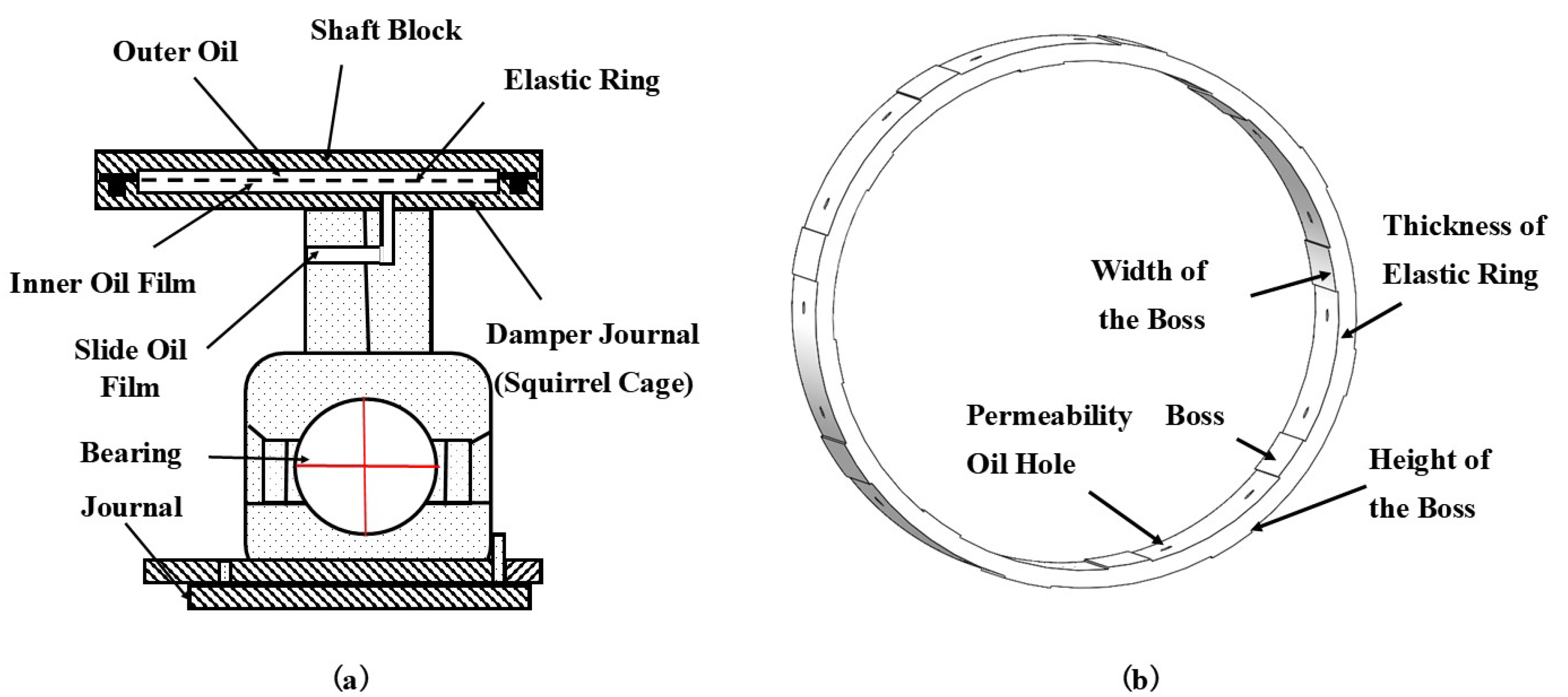
The ERSFD design ideal was that the elastic ring was added to the inner and outer ring of the traditional SFD. The double surfaces of the elastic ring were processed using staggered and evenly distributed bosses. The bosses on the inner surface were matched to the outer surface of the damper journal. The bosses on the outer surface were matched to the bearing seat. During the precession and rotation process, the damper journal was driven and subjected to varying the oil film supporting forces and the elastic ring variable supporting forces. This reduced vibration.
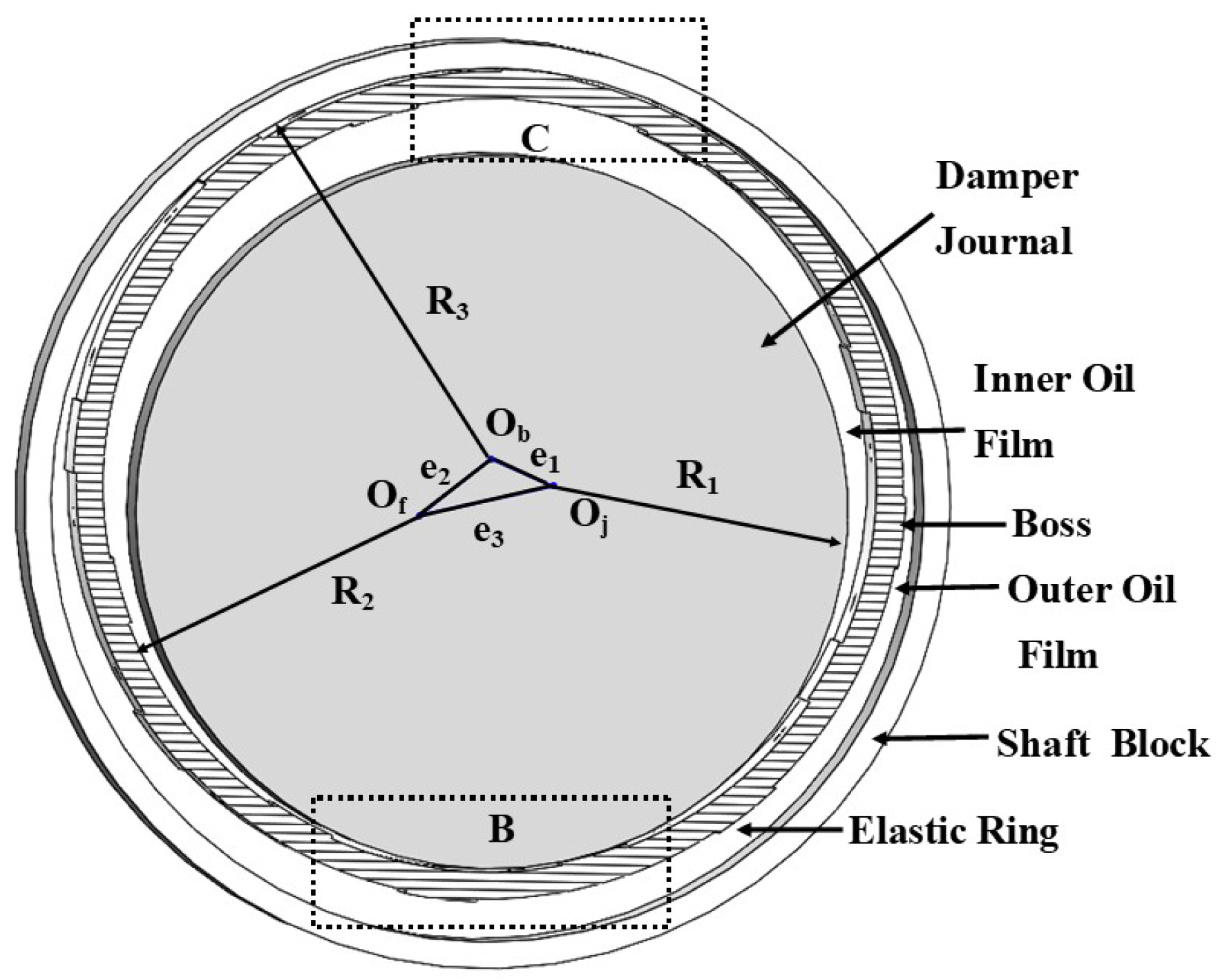
Figure 1 shows the ERSFD structure. The oil film and bearing seat were conducted from the inside to the outside of the structure in
Figure 1a, including the journal, bearing, slide oil film, damper journal, inner oil film, elastic ring, outer oil film, and shaft block. The inner oil film, the elastic ring, and the outer oil film are the research topics in this study. The elastic ring contains a boss and an oil hole, as shown in
Figure 1b. The simplified assumptions were made [
6,
18,
26]: (1) Only the velocity gradient of the oil film thickness direction was considered; (2) The incompressible flow conformed to Newton’s viscosity law; (3) The temperature effect and the journal curvature effect were not considered.
2.1. Basic Equations
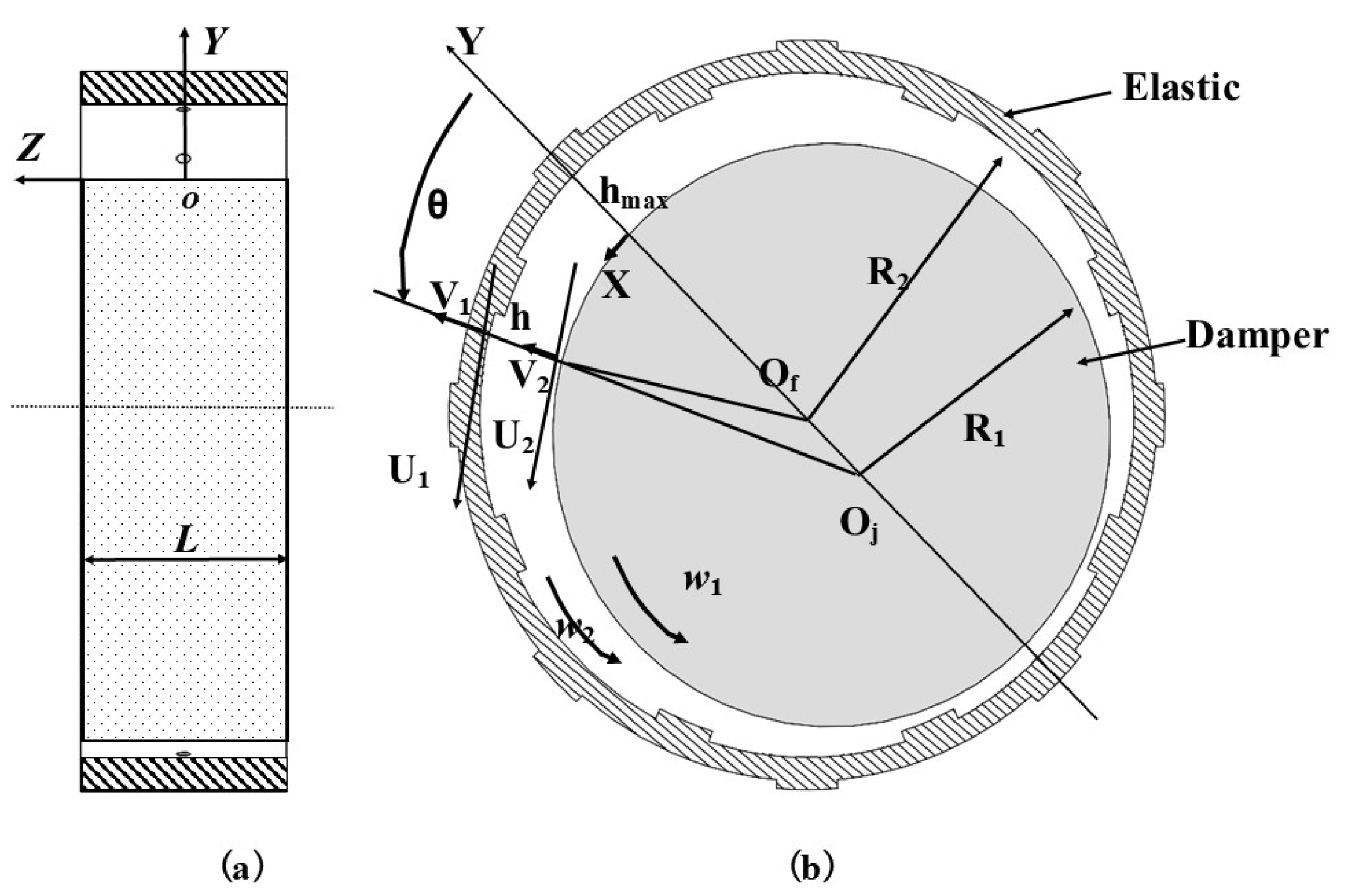
According to the geometric structures and motion states of the ERSFD, this section took the basic theory (the dynamic pressure lubrication theory and Reynolds equation of sliding bearings [
18]) as the starting point. First, the single-layer oil film is analyzed, as shown in
Figure 2. In the analysis process, the inner oil film of the damper journal and the elastic ring is taken as an example for analysis, and their structure is shown in
Figure 2a and
Figure 2b. The position is the inner oil film part in
Figure 1a, and the elastic ring is shown in
Figure 1b. The pressure equation of the single-layer oil film was established. Then, it was gradually generalized and extended to the multi-layers model. The oil film force models of the inner and outer oil film were established.
According to the construction methods of the Reynolds equation of sliding bearings, the precession speeds of the inner oil film ring and the damper journal were
and
, respectively.
Z was the axial direction along the damper journal. The partial speeds of the circular
X and the normal
Y of the circular surface on the damper were
u and
v, respectively. The flow outward through the upper surface
and the lower surface
was at the static speed
, which was the pore, gap, porous material, or other outward seepage speed. To the cylindrical coordinate
, the generalized Reynolds equation of the in-compressible flow in the traditional polar coordinate form was:
Considering the precession motion of the center
of the damper journal around the center
of the inner oil film, the precession angular speed was
, and
,
. Select
,
,
,
, and
, Equation (
1) was approximately converted to:
Neither the inner oil film ring nor the damper journal in the elastic ring extruded oil film damper rotates,
. When the damper journal only performed the circular precession around the center of the oil film, Equation (
2) was simplified as [
27]:
Similarly, the outer oil film pressure can be derived [
19]. The outer oil film pressure model was derived with Equations (2) and (3). In addition, the above transformation process in which the oil film pressure model of Equation (
2) extruded oil film damper included various motion states of sliding bearings and had the precession speed of the elastic ring and the damper journal. Equation (
3) was more consistent with the ERSFD geometric structures and actual working conditions, conducive to the subsequent study of four contact models of the elastic ring.
2.2. ERSFD Models
According to motion contacts and forces of the ERSFD, this section took the suspension model and the inner–outer bosses contact model as primary research objects, and then analogized the model construction ideas to complete four different contact models.
As shown in the above and following figures, is the journal radius. is the elastic ring radius. is the bearing seat radius. According to actual problems as in Equations (1)–(3), R could select , , and . Owing to the existence of the eccentricity during installation or movement, it is assumed that the eccentricity of and relative to the center of are and , respectively. The eccentricity of and is . denotes the viscosity coefficient. is the flow rate. represents the boss height. represents the boss thickness. The damper journal speed and the ERSFD speed are and , respectively.
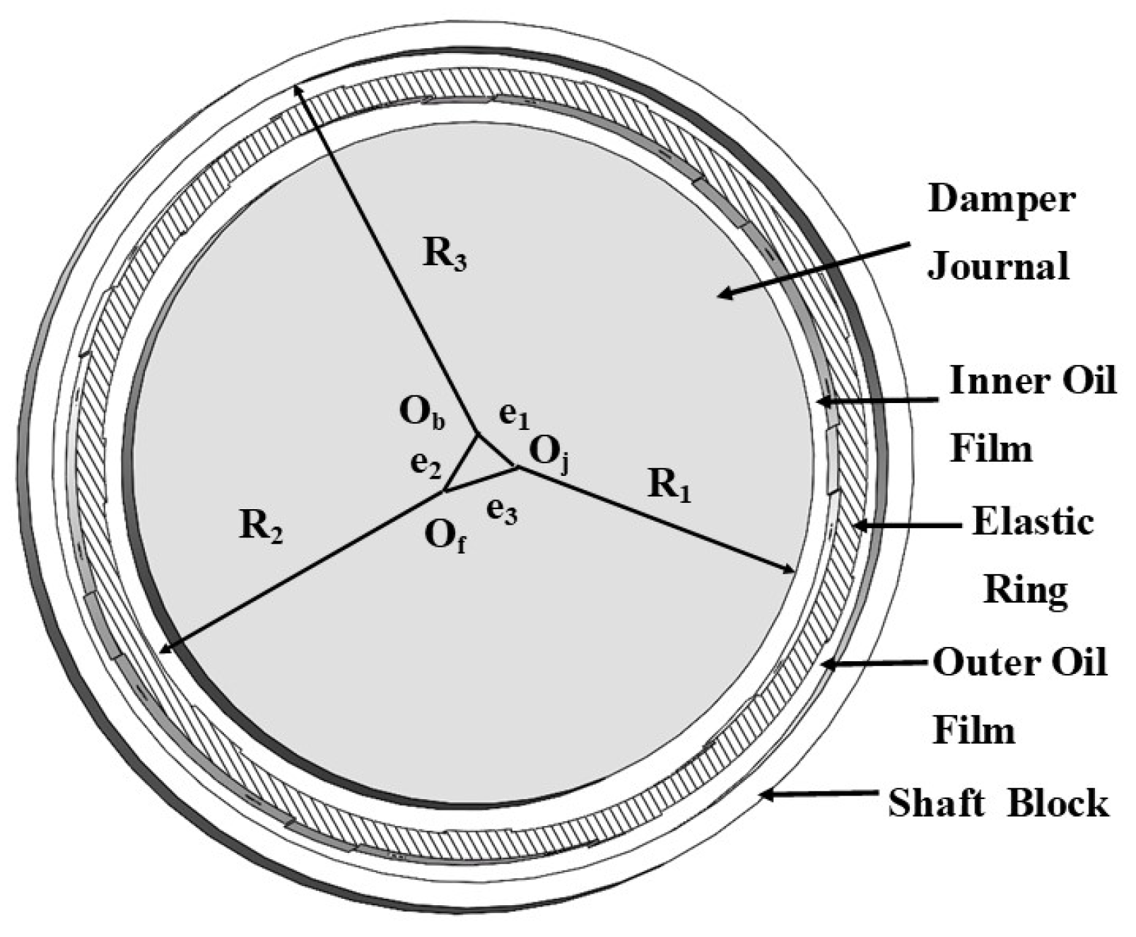
Suspension. The bosses did not contact the damper journal or bearing seat in the suspension. This state was similar to the motion state of the floating ring of the FRSFD [
26], as shown in
Figure 3. By analyzing motion states of the floating ring of the FRSFD and pressure equations [
26,
28], pressure equations in the suspension [
29] were deduced as follows, combined with the geometric position relation of the ERSFD structures.
where Equation (
4) describes the inner and outer pressure equations, respectively.
and
denote the inner and outer pressures, respectively.
and
include angles from the maximum thickness, respectively, which are positive counterclockwise. Considering the height of the bosses,
, otherwise,
.
is the inner gap, and
is the inner thickness, and
is the outer gap, and
is the outer thickness. The eccentricities are
.
.
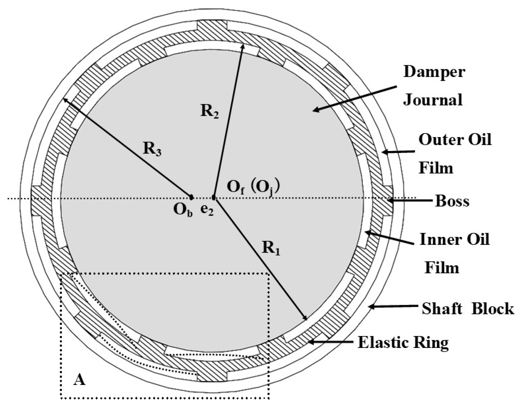
Inner–outer bosses contact. The inner bosses contact the damper journal and the outer bosses contact the bearing seat in the inner–outer bosses contact. This contact was similar to the motion state of the single-structure ring of the ERSFD [
17], as shown in
Figure 4. By studying the single-structure ring of the ERSFD [
17,
18], oil film pressure equations [
29] were deduced as follows.
where Equation (5) describes the inner and outer pressure equations.
and
are the included angles from the maximum thickness, respectively, which are positive counterclockwise.
is the inner gap, and
is the inner thickness, and
is the outer gap, and
is the outer thickness. The eccentricity are
,
.
Inner-bosses contact and Outer-bosses contact. The inner bosses were contacted with the damper journal in the inner-bosses contact, as shown in area
B of
Figure 5. The outer bosses were contacted with the bearing seat in the outer bosses contact, as shown in area
C of
Figure 5. The pressure models of contact areas and the oil film areas were deduced from the different combinations of Equations (4) and (5), respectively [
30]. According to the relationship between the two combination types of models and their corresponding parameter selection adjustment, the inner-bosses contact and the outer-bosses contact are further described [
30].
- (1)
The oil film force model for the inner-bosses contact is the suspension’s outer oil film pressure model and the inner oil film pressure model of the inner-outer bosses contact.
- (2)
The oil film force model of the outer-bosses contact is the suspension’s inner oil film pressure model and the outer oil film pressure model of the inner-outer bosses contact.
Furthermore, it was compared with the typical squeeze film dampers of SFD, PSFD, and FRSFD.
- (1)
The transient pressure model of the oil film of the squeeze film damper (SFD) with oil film alone
- (2)
The transient pressure model of the oil film of the porous squeeze film damper (PSFD) included the fluid amount of the oil hole
- (3)
The transient pressure models of the inner and outer oil film of the floating ring squeeze film damper (FRSFD).
where,
p,
, and
describe the pressure.
and
are included angles from the maximum thickness, respectively. The precession speed of the journal damper was
, and the precession speed of the elastic ring was
.
and
are the thickness of the inner and outer oil film.
Compared with the above typical oil film pressure models, it can be seen that the analytical thinking and mathematical models of the ERSFD are consistent with those of the squeeze film dampers in SFD, FSFD, and PSFD, if the thickness of the elastic ring and convex platform are not considered. Equations (4) and (5) contained the thickness, height, width, flow rate, other relevant geometric parameters, and actual motion states of the ERSFD, damper journal, and bearing seat, such as static and dynamic eccentricities. The elastic deformation of the ERSFD could also be described by selecting different oil film clearances, such as the misalignment and its variability [
31]. Moreover, the transformation process of various contacts was described by adjusted parameters, which were more consistent with the actual structures and working conditions.
In summary, oil film pressure models of four different contacts were constructed in this study, which improved the oil film pressure models of the ERSFD proposed by Russian scholars. Moreover, this also described two situations during installing dampers in real aero-engines. The first was that the initial installation state was the inner–outer bosses contact. The damper journal precessed and extruded staggered layout bosses during the initial process. The ERSFD and the flowing oil film played supporting and damping effects between the oil holes, as shown in
Figure 4 and the deformation area
A. As the platform was damaged,
Figure 3 and
Figure 5 show that this contact gradually evolved into the suspension. Second, the original installation state was the suspension. The inner and outer bosses existed when the journal precession amplitude was too large, as shown in the contact areas
B and
C in
Figure 5. This condition was more common, and the construction idea of the oil film pressure model of four contacts proposed in this study was to describe the dynamic transformation process of different contacts under this condition.
Therefore, it is beneficial to analyze the structure of the SFD from the aspects of the design and principle by studying systems and oil film pressure models.
3. Approximate Analytical Solutions
The approximate solutions of oil film pressure models were generally obtained by the short and long bearing approximate theories. The circumferential pressure was far less than the axial pressure when the axial radius ratio was small (the short bearing). The circumferential pressure was ignored. On the contrary, the axial pressure was ignored when the axial ratio was large (the long bearing). According to the Aero-engine Design Manual, the axial radius ratio of standard engine dampers was between 0.05 and 0.31. Moreover, from the mechanism perspective, the finite-length bearing approximate theory had a better effect. Therefore, this section analyzed and deduced the approximate analysis based on structural characteristics and actual working conditions of the ERSFD.
3.1. Determination of Boundary Conditions
The oil film boundary conditions (the rupture and second form boundaries) depend on the geometry and movement parameters of the bearing, the roughness of the section, state parameters of the oil (surface tension, points of the containing gas air-pocket pressures), physical properties, and dynamic effects of the Reynolds number. In this section, the logical relations of static conditions (Sommerfeld, Gumball, Reynolds, Floberg, and continuous static conditions), local dynamic conditions (Hahn and continuous dynamic boundary conditions), and attached boundary conditions were discussed [
6,
13,
14,
32]. Combined with the geometric structure, actual working condition, the derivation process, and using the finite coverage theorem, the boundary constraint condition of the multi-structure and multi-interval dynamic
oil film suitable was:
where the multi-structure refers to bosses, oil holes, and other structures. The multi-interval refers to the interval between bosses and the gap between adjacent bosses
and
, where
i and
j represent the number of boss clearances and bosses, respectively. According to the finite coverage theorem, the division between regions was reasonable and the interval set existed. Dynamic
refers to overall interval length
[
14].
is the eccentricity.
can be regarded as a circular motion.
can be regarded as an elliptical motion or other motions.
3.2. Finite Length Bearing
The oil film pressure model is a two-dimensional nonlinear partial differential equation with second-order variable coefficients and three independent variables, which is very difficult to solve. From the boundary conditions of existing ideas and the form of the Reynolds equation, the oil film pressure expressions are adopted by the short bearing, long bearing, variational, small parameter, and separation variables methods [
13,
19,
33,
34]. Considering the existence and structure of solutions of differential equations, it is necessary to select the appropriate solution structure to facilitate solving the analytical solution expression. For example, the experimental pressure function
was based on the variation theory. The function
was selected in the ‘Rotor Dynamics’ and the ‘Aero-engine Rotor Dynamics’.
was selected in the ‘Aeroengine Design Manual’. The different oil film pressure equations of four contacts are solved using the structure and existence theories of the partial differential equation (the adding and multiplying form) [
11,
12,
13] in this section.
The right side of Equations (4) and (5) were briefly described as a function of the eccentricity, precession velocity, and rotation angle. The general oil film pressure equation was transformed,
where
.
, and
are determined by Equations (4) and (5). In other words, Equation (7) realizes the general description of oil film pressure models with different contacts mentioned above, conducive to subsequent analysis and discussion. The eccentricities are
, and the precession speeds are
.
As the relevant theory of the partial differential equation, the solutions of Equation (7) exist, corresponding to the sum of the particular solution
of the inhomogeneous equation and the general solution
of the homogeneous equation, which can be obtained by substituting
and
into Equation (7) [
12,
13],
Considering that the extruded oil film damper has seals at both ends, the boundary conditions of the inhomogeneous equation and homogeneous equations are:
where
L was the length of the journal.
D was its diameter. The positive pressure area is
, and the local interval
is selected when considering oil film pressures at the boss and between two bosses.
The inhomogeneous Equation (8) is split into four differential equations.
From boundary conditions, we obtained:
Furthermore, the specific situation can be given by the actual research scope. According to the conditions of separating variables,
) is selected and substituted,
According to the value range of
T [
11,
12,
13], we obtained:
The oil film pressure in different contacts is derived as:
The radial and circumferential oil film forces in different contacts are:
where
,
,
,
,
, and their related operations can be obtained from Booker integral formulas [
35] and the following
Appendix A.
3.3. Method of Approximate Solution Expressions
There were two difficulties in obtaining approximate analytic expressions of Equations (14) and (15). Because the flow term
of permeability oil holes is considered,
is introduced and its reintegration with
,
,
, and
. This solution is relatively complex. The next is that
is not easy to double integrate. The difficulty of solving the above two equations was far beyond the derivation and the solution idea of the original Booker formulas. Therefore, most literature avoided this particular term by simplifying the geometric structure [
1,
3,
12,
19,
21], or directly adopting numerical calculation methods without analytic forms [
10,
14], which has been problematic for many years.
Based on basic Booker formulas, the separation, integration by parts, recursive adaptive Simpson, polynomial fitting, variable integral upper and lower limit, integrand function with parameters, integral median value theorems, and other strategies were used to solve the approximate analytic solution of the corresponding simple form.
. Using separation of variables, integration by parts, and other methods to propose a semi-analytical and semi-numerical solution and derive the integral formula, including parameters. The specific analysis was as follows. Get:
In combination with Equations (14) and (15), it was necessary to discuss the integral terms of formulas
and
. According to the idea of the function transformation and integrand function with parameters, the above two expressions were respectively regarded as functions of
.
- (1)
Combination with the range of the ERSFD, get
, and other situations were similar. Select:
because,
and
- (2)
The solution of Equation (21) was related to
. When
, it was converted to:
However, the corresponding integral Equation (23) was also very difficult to compute analytically. Therefore, the recursive adaptive Simpson method was used to calculate the integral and obtain the numerical solution of . Then the polynomial fitting method was used to select the appropriate function expression within the allowed error range. Moreover, the value of static eccentricity was generally between 0.1 and 0.35, in which Equations (20) and (23) were approximately linear. To simplify the calculation, the linear expression was selected. It should be noted that the numerical calculation method was not suitable for directly solving Equation (20), and sometimes there were imaginary roots, which were not conducive to subsequent analysis.
Based on the above solution ideas and methods, this study improved and expanded the Booker formulas, as shown in the
Appendix A, which tried to propose a semi-analytical and semi-numerical way to solve this problem.
. It contains
and
Z, and this kind of problem was encountered in solving oil film forces by other methods [
11], such as, the function
mentioned in the variational method. The integral mean value theorem was used to improve in this section. Select:
- (1)
If
was continuous on the interval
, there was at least one point
, so that:
If
, so
- (2)
If
was continuous on bounded closed region
D:
, and
was the area of
D, then there existed at least a point
in
D, such that
,
The feasibility of the simplified method was discussed theoretically, and the solving process was similar to Equations (14) and (15) and can be simplified; a reasonable approximate analytical solution can also be obtained.
3.4. General Expressions
The improved and extended Booker formulas and approximate solution methods were extended to the short and long bearing approximate theories, and related forces were obtained.
General expressions of oil film pressures and oil film forces were:
where
includes
,
,
, and
.
includes
,
,
, and
.
includes
,
,
, and
.
includes
,
,
,
,
, and
.
includes
,
,
,
,
, and
.
includes
,
,
,
,
,
, and
.
and
are the function
(Z), and
F consists of the radial force
and the circumferential force
. The related formulas are obtained from the corresponding formulas of (13)–(15) and (28)–(37).
Moreover, oil film pressures or oil film forces can be analyzed from three parts: the structure, motion state
, and sealing state
. The general expressions for three approximate theories in arbitrary intervals
and
were given and further discussed. Without considering
and its corresponding simplified formula, the expression in this study was consistent with that [
11,
12]. When
(
) selects the functions corresponding to functions in [
32,
33,
36,
37], the oil film force expressions of various simplified cases involved were the same. It also proved that this section’s oil film force expression was correct. The method of solving the equation and improving Booker formulas was reasonable and correct in this study. The next step mainly focused on the engineering application and analyzed the relationship between relevant parameters in different contacts.
3.5. Analysis of Oil Film Characteristics
The above solution methods and improved Booker formulas supplemented the relevant research work [
28]. This section further analyzed and studied the general expressions of the stiffness and damping provided by oil film forces in the dynamic equilibrium state so that it was more practical in the practical engineering and the rotor system dynamics Equation (
1).
3.5.1. Oil Film Characteristics
According to the dynamic equilibrium theory, the damper journal precesses around the elastic ring with a certain eccentricity at the constant speed, and the elastic ring precesses around the bearing seat with another certain eccentricity at the consistent speed. When the damper journal may cause a small initial displacement or velocity due to some external disturbance, eight general equations for dynamic characteristic coefficients of oil films were obtained from transient oil film force equations [
17],
3.5.2. Solution Methods of Characteristic Expression
Four contacts described by Equations (4) and (5) were affected by factors such as the eccentricity of different states, clearance and thickness of oil film, and rotational speed of damper journal and elastic ring. , , , and have , and , and as its composition functions, , , . Each Booker item in each contact has different meanings of . So, the derivative of and cannot be taken directly, and the derivative concerning , , and cannot be substituted. Equations (38) and (39) were also not easy to obtain. Here, the partial solution strategies based on geometric structure and separation of variables were as follows.
- (1)
Conversion.
In Equation (
4),
and
. However,
is not in the original expression. According to the geometric structure and vector solution,
In Equation (5), and .
In others, the oil film thickness can be adjusted according to the actual situation to describe the elastic ring deformation without conversion;
- (2)
and were regarded as two independent variables, and the oil film force was decomposed into two parts, including and . This section contains only without . The variables of Equations (35) and (36) were separated first, and then the derivative was obtained by parts. However, the inner oil film force in the suspension was complicated. In this case, and should be differentiated concerning and , respectively, and then summed up as the overall derivative result with the respect to ;
- (3)
The rotational angular speed of the damper journal and the elastic ring were derived.
Taking the synchronous motion under the semi-oil film theory as an example,
and
were the assumption of
Section 3.2. The simplified Equations (28)–(37) can be analyzed without considering the elastic ring compared to theoretical conclusions.
- (1)
- (2)
- (3)
Finite length bearing. These were obtained by the approximate function of Equations (14) and (15), which was between the short and the long bearing.
Based on the above, the stiffness and damping of four different contacts can be obtained by substituting the relevant parameters of different contacts (the clearance and thickness), which were simplified to find the equivalent stiffness and damping in the steady-state.
Moreover, the oil film characteristics of sliding bearings and more cases were further obtained according to (1)–(3), and the relevant theories in [
1,
6,
23,
29,
32] were also improved and corrected.
4. Discussion and Analysis
The structural parameters of the ERSFD were as follows. The length of the journal was m. Its diameter was m, and its radius was m. The inner radius of the elastic ring was m. The inner radius of the bearing seat was m. The thickness of the elastic ring was m. The height of the bosses was m. The width of the bosses was m. The precession speed of the journal was rad/s. Due to the synchronous precession between the journal and the elastic ring, it can be considered to describe the motion of the center of the circle in the stable state with the same fixed value of each eccentricity or to describe other movements in the unstable state with different values. In this study, the relatively simple case is considered for analysis, and the principle of other issues is the same. It is assumed that the damper journal and the elastic ring move synchronously. The eccentricities among the elastic ring, damper journal was m and the rate of eccentricity was and the number of bosses was .
In this part, the approximate analytical solutions of oil film pressures and oil film forces of the ERSFD under three approximate theories were analyzed from general structures and motion states of the ERSFD. The elastic deformation of the ERSFD could be described by selecting different oil film clearances.
4.1. Structural Parameters and Motion States
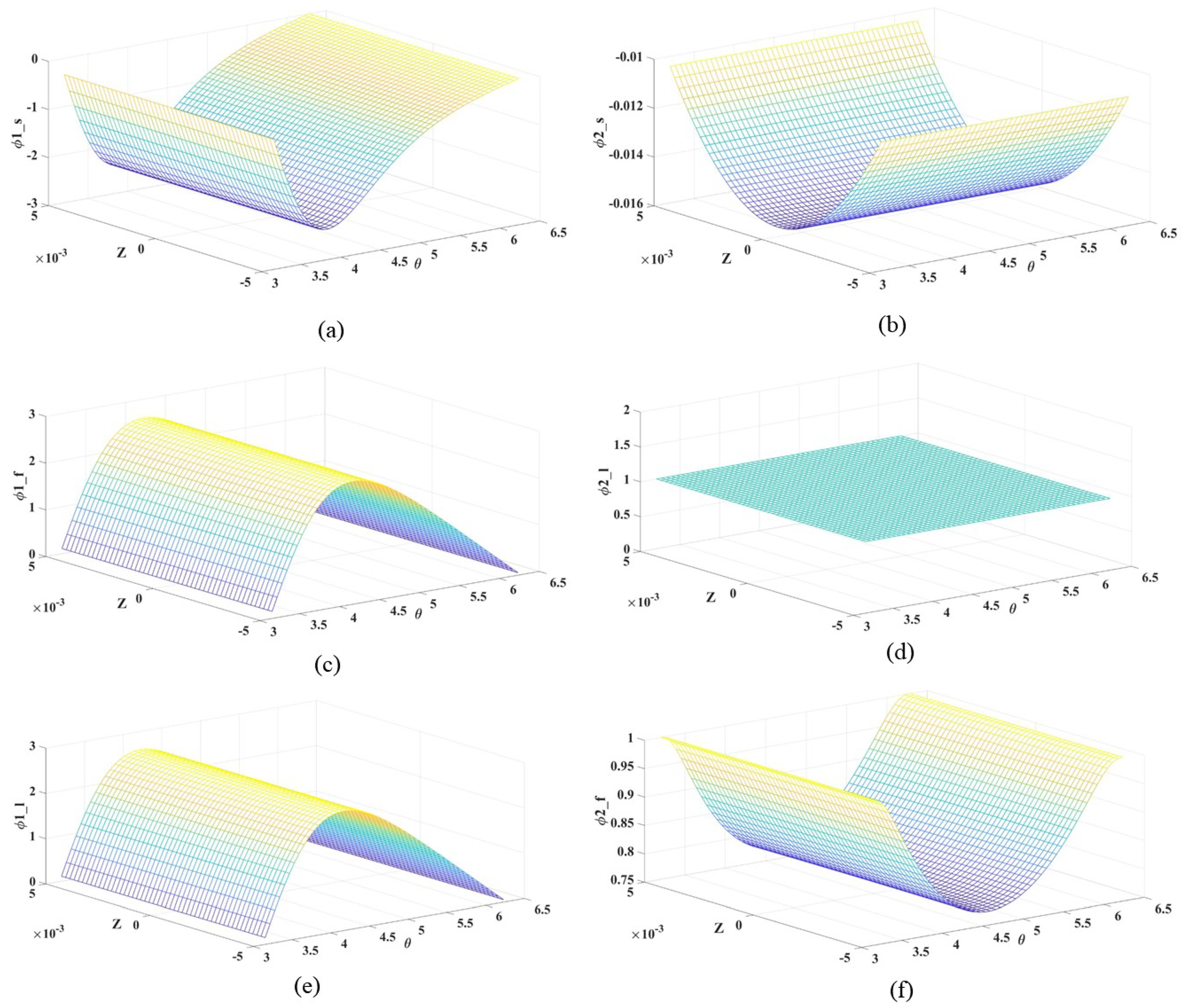
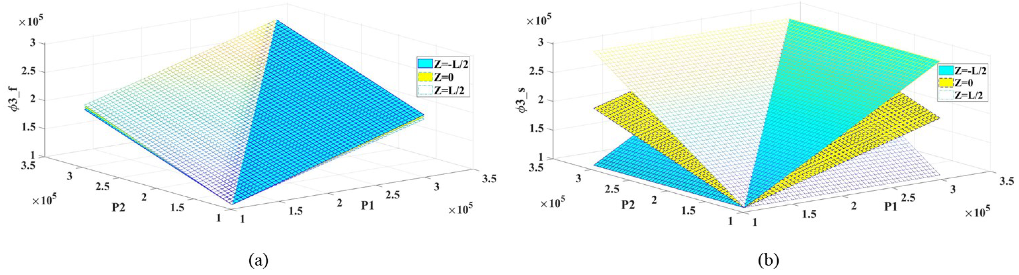
Figure 6 shows the relationship between
and
functions under three approximation theories is further analyzed.
Figure 6a,c,e describes
.
In the pressure expression of the short and long bearings,
and the function of
Z are independent of each other. The finite length bearing considers the length of the journal, and
is a mixed function of
and
Z. Under the condition of no-end seal, when the pressure at both ends are zero,
is a quadratic function of
Z under the short bearing, as shown in
Figure 6b. Under the finite length approximation theory, the value of
is the fixed value of
L, as shown in
Figure 6d. Under the finite length bearing, the compound function of
equals
Z is related to
and
Z, as shown in
Figure 6f.
This is related to the basic assumptions. is related to the state of motion and is related to the assumption of the length of the journal. Moreover, in the finite length bearing lies between and .
4.2. Relationship of Different Oil Film Pressures
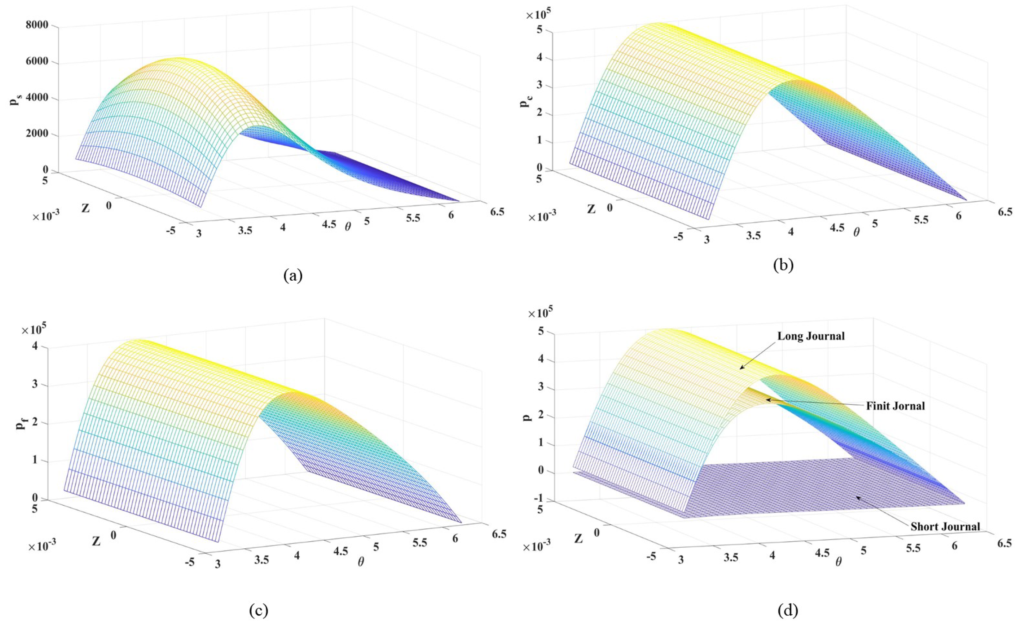
Figure 7 shows oil film pressures under three approximate theories. Compared with the difference method [
26,
36], the variation trend obtained in this study is consistent, indicating that the approach adopted is feasible and lays a foundation for subsequent research.
Figure 7a–c points out that the pressure of the short bearing is minimum, and the pressure of the long bearing is maximum. Putting the three figures together, the expression of the finite-length bearing is between the pressures of the short and long bearings, as shown in
Figure 7d. Moreover, as the axis ratio increases, the pressure of the finite bearing becomes closer to that under the long bearing.
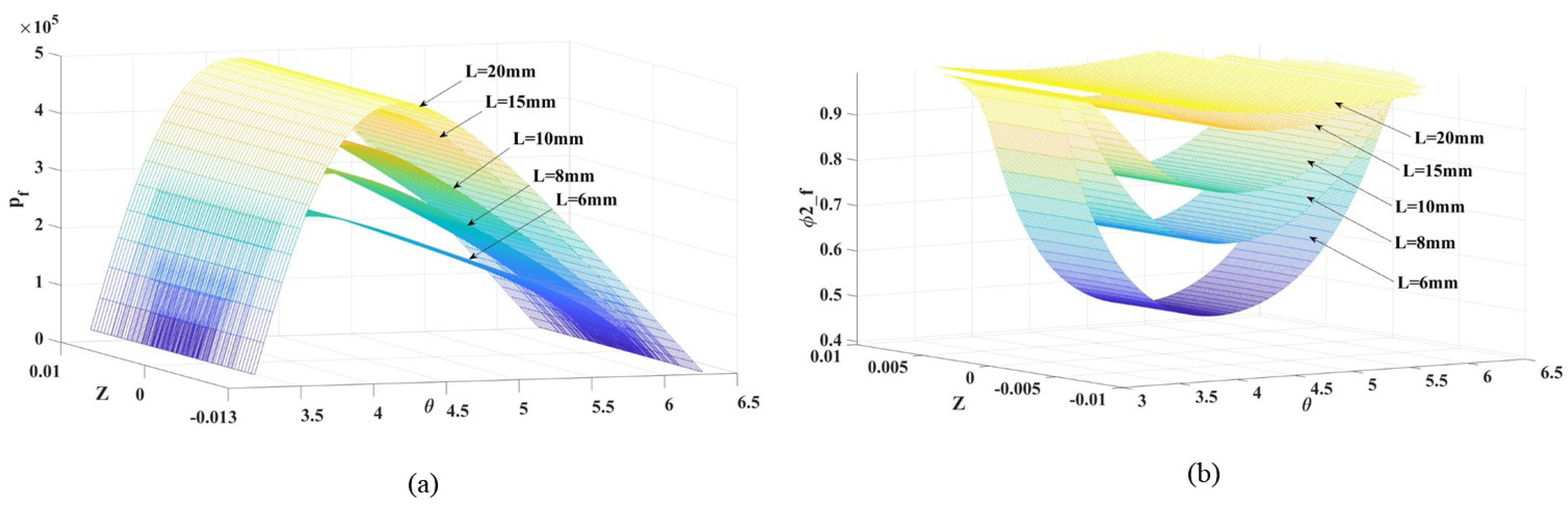
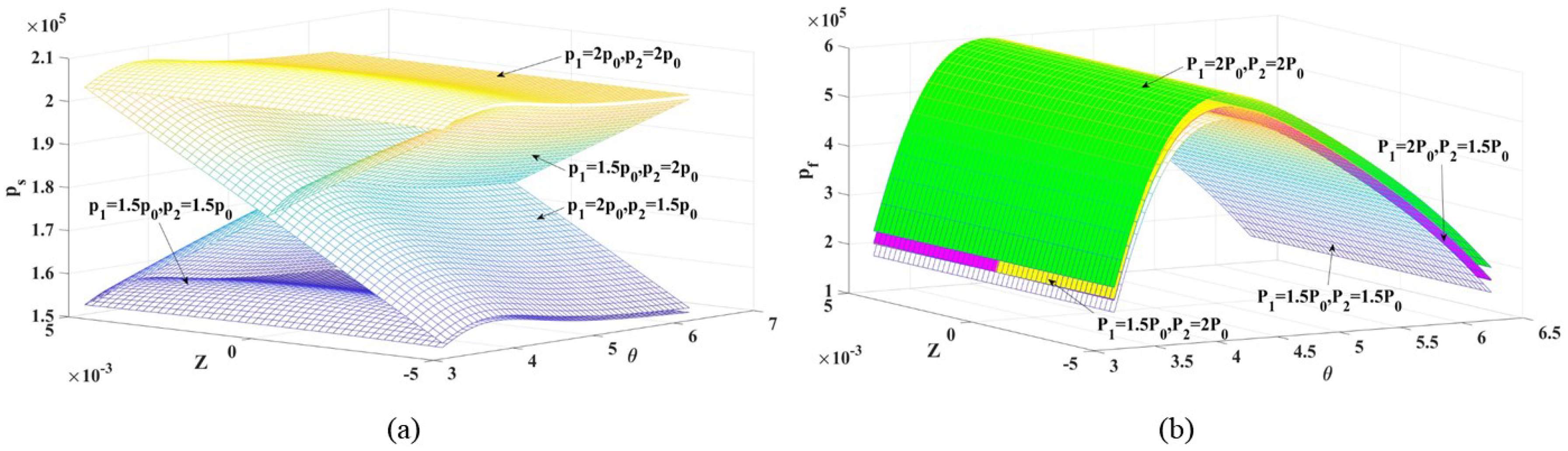
Figure 8 shows the variations and pressures of the finite length bearing. Theoretically, suppose that the short and long bearings are regarded as the two ends of the pressure function and force function, there should be some value in the middle (the corresponding value under the finite length hypothesis), as shown in
Figure 8a,b.
Furthermore, Equations (24)–(27) can be solved. From the process analysis of the short, long, and finite-length bearings, under the background of the practical engineering research, it is necessary to seek analytical relations of approximate functions closer to actual working conditions, which can be obtained from basic Booker formulas, the improved solution methods, and the formulas of this study in the
Appendix A.
4.3. End Sealings
The approximate theory generally selects the pressure at both ends of the journal seal as zero. In reality, the journal ends the sealing and needs to consider its sealing. However, the oil film pressure formula has no end-seal pressure term based on the long bearing. Therefore,
Figure 9 and
Figure 10 show that the end sealing is considered in the short and finite-length bearing.
The influence of the short bearing is more significant than that of the pressure term (
and
) under the long bearing.
Figure 9a,b shows that the main reason is that the bearing radius affects the finite length bearing.
If sealing pressures at both ends are equal, the oil film pressure under the short bearing is an overall and downward translation. A crossover phenomenon occurs when the sealing pressure at both ends is different, as shown in
Figure 10a. The finite length bearing is less affected by different pressures at both ends and is generally translated up and down, as shown in
Figure 10b.
4.4. Motion State
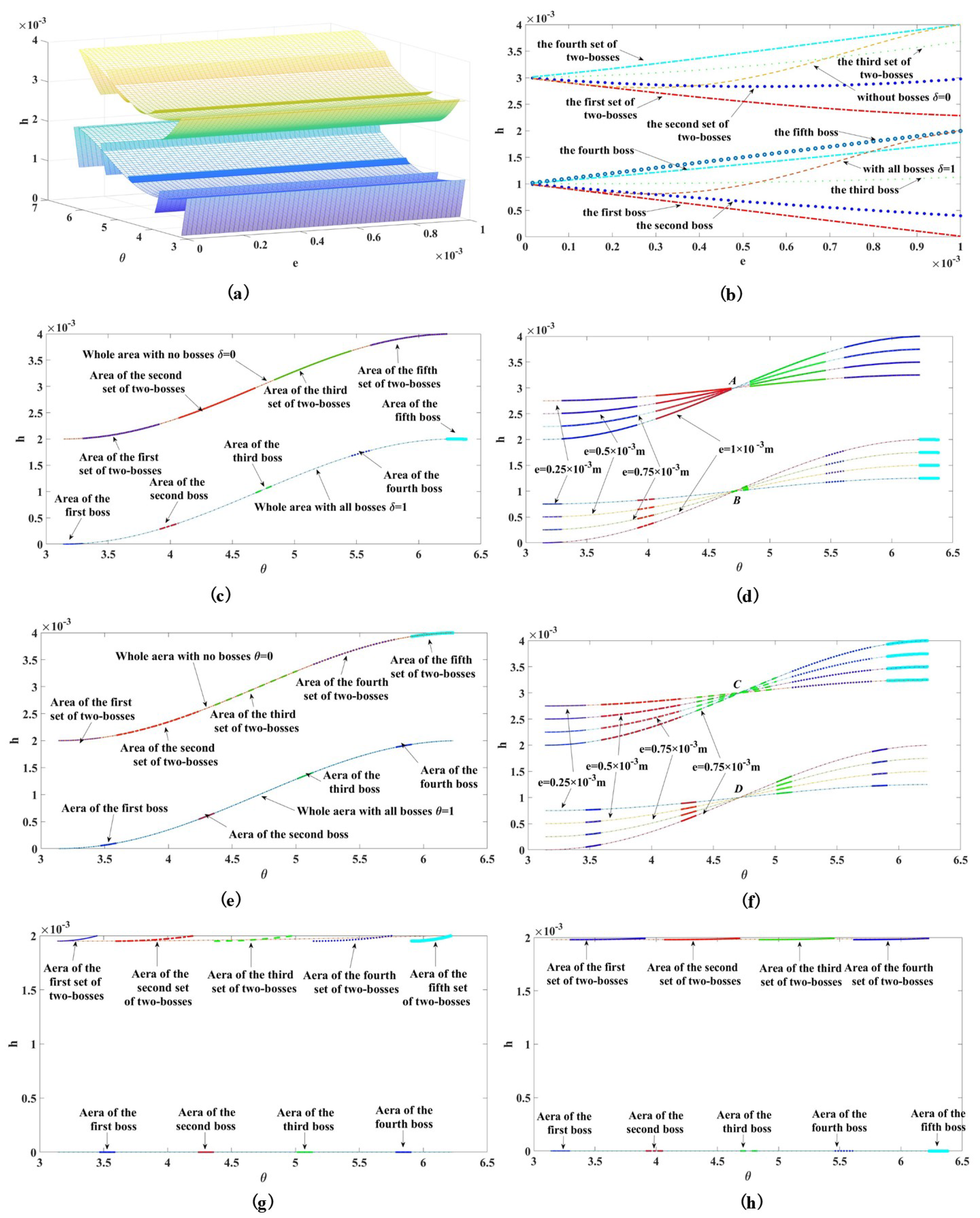
Figure 11 shows the thickness changes in the synchronous motion. Three design cases about the bosses structure, elastic ring without bosses I (keeping its thickness unchanged), and elastic ring without bosses II (the overall thickness is the boss height and original thickness of the elastic ring) were analyzed.
There was a significant difference in the thickness at bosses and that between adjacent bosses, as shown in
Figure 11a. With an increase in eccentricity, the thickness changes at different positions, and the trends are also different, as shown in
Figure 11b. The inner and outer thicknesses exhibited opposite changes in the same angle interval, which was mainly determined by the layout position of bosses, as shown in
Figure 11c,e,g,h. As the eccentricity increased, the thickness gradually decreased in the first interval and progressively increased in the second interval, as shown in points A, B, C, and D in
Figure 11d,f. When the eccentricity reached the maximum state, the contacts changed,
Figure 11g,h shows that the thickness at the boss decreased to 0, and the oil film thickness between bosses remained the same. If the elastic ring does not contain bosses I, the difference in the thickness is consistent with the difference between the two bosses. The elastic ring does not contain bosses II, and the thickness change is consistent with the change in the bosses. The oil film thickness of bosses varied between them.
It was verified that the design of the ERSFD can effectively improve the oil film performance. Because the thickness function selected in this study is relatively simple, although a slight improvement in the thickness between two bosses is shown in
Figure 11h, its trend transformation is affected by the elastic deformation and the flow rate. Thus, the related function formula can be improved for a more reasonable description.
4.5. Oil Film Forces
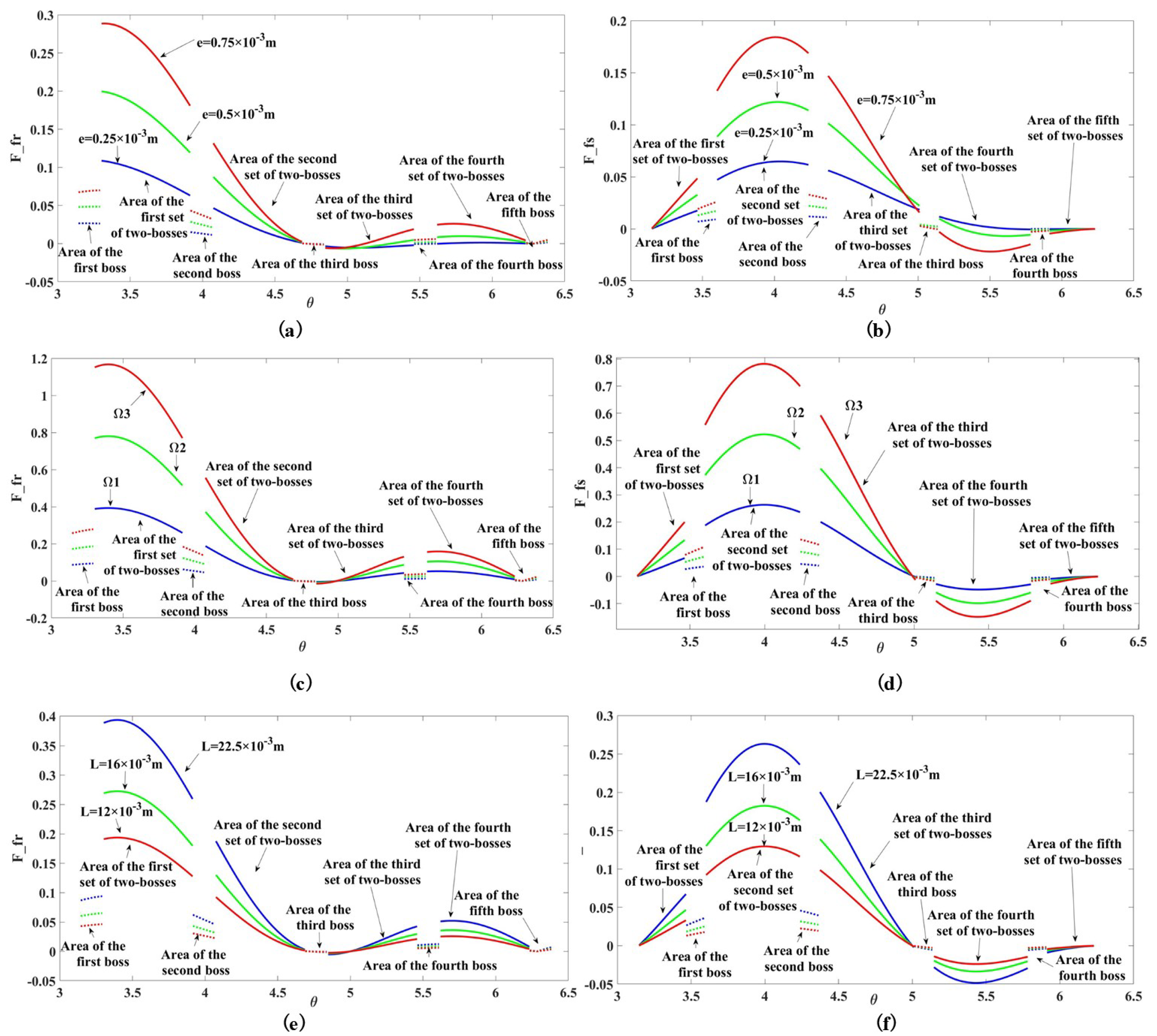
Figure 12 analyzed the oil film force about four different contacts under the finite length to describe the fundamental structural characteristics. Overall, the oil film forces of the boss and its region varied significantly, but the trend of each part remained unchanged. Journal extrusion decreases the thickness with increased eccentricity, and the double oil film forces gradually increase.
The force of
is higher than that of
because the thickness increases the angle gradually, and the force decreases accordingly. The outer oil film is close to zero in
and even has a negative value when the static eccentricity is small, indicating that no force is generated. It is generally zero, as shown in
Figure 12a,b. Similarly,
Figure 12c,d explains that the double oil film forces gradually increased with the rotational speed. In structural, with a decrease in the length of the journal and the diameter of the axle becoming smaller, the force under the finite length bearing tends from the long to the short bearing, as shown in
Figure 12e,f.
4.6. Oil Film Characteristics
The principal radial stiffness and circumferential principal damping in the suspension were used to analyze oil film characteristics, as shown in
Table 1 and
Table 2.
Other conditions were similar to in the study. In
Table 1 and
Table 2, oil film characteristics at 0.25, 0.5, and 0.75 of the axial diameter ratio of the boss, the clearance of bosses, and the interval of the semi-oil film were given, and the stiffness and damping of the transient oil film at each segment point and interval were solved. If the short term was not considered, it could be converted to the equivalent oil film characteristics of the damper or sliding bearing.
Table 1 and
Table 2 list that the oil film characteristics of bosses were higher than those of the boss due to the permeability and oil film flow. Moreover, with the axial radius ratio increased, the oil film stiffness and damping gradually increased, and the characteristics of the finite length bearing were close to those of the long bearing.
According to the stiffness and damping formula in
Section 3.5, in the steady-state of circular motion, the circumferential damping does not change with the precession velocity, and the radial stiffness increases with the increase of precession velocity. There are complex nonlinear relations between the damping and stiffness and the eccentricity. It is consistent with the conclusion [
14,
37].
5. Conclusions
Considering structural parameters, oil film pressure models of the ERSFD under four different contacts were constructed. The multi-structure and multi-interval dynamic boundary conditions were selected.The general expression solutions of three bearings’ inner and outer oil film forces were analyzed using the Simpson, Polynomial, integrated parameters, and mean values methods.
- (1)
Four different pressure models of the ERSFD were established by analyzing structural characteristics and motion states. A semi-analytical and semi-numerical method was proposed to improve and expand Booker formulas. The structures and expressions of analytical solutions of oil film forces under three approximate theories were obtained. The rationality and correctness of the theoretical derivation in this study were verified by comparing with the expressions in the existing literature;
- (2)
Three oil film forces conversion relationships of the short, long, and finite-length bearings are pointed out. Moreover, the thickness and force of bosses or the boss part have apparent changes, but the changing trend of each element is consistent. Moreover, with the eccentricity increased, the thickness decreased and the forces increased gradually. The inner and outer forces gradually increased as the precession speed increased. It was verified that the design of the ERSFD can effectively improve performance. The circumferential damping and radial stiffness decrease with the increase of eccentric moment. These have specific reference and application values for constructing relevant dynamic mathematical models;
In this study, the oil film force of the ERSFD under different contacts was taken as the starting point. The relationship between the ERSFD structure and mechanical parameters was obtained by theoretical derivation and numerical analysis, including the effective length of the damper, journal radius, oil film gap, viscosity coefficient, and oil film pressure, force, stiffness, and damping, which provides theoretical support for the optimization and analysis of mechanical parameters. The average method, transfer matrix, and incremental harmonic balance methods have been combined in the concentrated mass rotor system. Next, the semi-numerical and semi-analytical solutions will be explored by combining experiments or real machines. It has a reference and application value to optimize mechanical parameters and analyzes the correlation dynamics model.


