Article

The Use of Computed Tomography as a Teaching Resource for the Teaching of Structural Concrete in the Degree of Civil Engineering

Department of Civil Engineering, University of Burgos, 09001 Burgos, Spain
*
Author to whom correspondence should be addressed.
Educ. Sci. 2021, 11(12), 768; https://doi.org/10.3390/educsci11120768
Submission received: 16 September 2021 / Revised: 19 November 2021 / Accepted: 22 November 2021 / Published: 29 November 2021

Abstract

:
This paper shows a teaching experience related to the use of computed tomography in the teaching of concrete for undergraduate students of the civil engineering degree. This experience reveals that computed tomography is a powerful tool to facilitate the understanding of all those aspects related to the microstructure of concrete, thus facilitating comprehension of the correlation between the microstructure and its macroscopic response. In addition, students showed a greater motivation and interest in the subject, which promotes better academic learning. A pilot test was carried out to evaluate the viability of these practices and to analyze the teaching impact of this activity. The results show that students were very interested in the use of new technologies in teaching and, more particularly, in the use of computed tomography. The students satisfactorily received the project. A greater motivation of the students in the subject was also observed, which resulted in better grades when compared with those of previous courses. The results reveal that the average grade of the students rose by around 8%, and a higher percentage of students achieved higher scores when compared to the previous five years.

1. Introduction

The use of new and emerging technologies for teaching purposes may often represent an advance in teaching methodologies and student learning [1,2]. The degree of civil engineering is a good example of this. There are many examples of the use of technologies, initially developed with scientific or technological reasons, in teaching, such as, for example, augmented reality in science [3], engineering [4,5], architectural studies [6], history [7], or education [8,9], 3D printing in medicine [10,11,12,13] or engineering studies [14,15], virtual reality in medicine [16,17,18], education [19,20,21], or crime science studios [22], nuclear magnetic resonance in medicine studies [23,24,25,26], or apps in engineering [27,28] among others.
The new and emerging technologies have many advantages from the academic point of view, among which are increased student participation, learning by entertaining, saving time and/or space, raising motivation and attention levels, and increasing cooperation [29,30,31,32,33]. Another advantage is that the new and emerging technologies supports approaches such as constructivism, learning by doing, and authentic learning, which serve to make students active in the learning environment [34,35].
One of those disruptive technological advances developed in recent years is computed tomography (CT). It is a non-destructive test which allows characterizing the internal structure of matter on a microscopic scale. The method is based on the loss of energy that X-rays experience when passing through matter, according to the Beer–Lambert law (Equation (1)).
I = I 0 · exp [ μ ( s )   d s ]
where I is the final intensity of the X-ray, I0 is the initial one, and μ(s) is the linear attenuation coefficient along the path. This parameter depends mainly on the density ρ of the matter that the X-ray passes through during its path.
A CT scanner consists of an X-ray emitter and an intensity detector. The sample is placed between them and during the scanning process it is crossed by X-ray beams in different directions and at different heights. The scanner measures the initial and final intensity of all X-rays, thus finally determining the density at all points in the sample.
The result of a CT-scanning process is a set of images or a stack in which each image represents a sectional slice of the sample at a given elevation. Using digital image processing programs, it is possible to group all the images in the stack, generating a spatial image. The dimensions of the voxels (spatial pixels) determine the resolution of the three-dimensional image. In addition, each voxel corresponds to a grey value (in a range from 0 to 65,535, in the case of 16 bit images) that is associated with the mean density of the voxel. Lighter shades of grey correspond to high densities, while shades of darker grey indicate low densities.
One of the major limitations of computed tomography equipment is sample size. Currently, maximum sample sizes range from about 15–20 mm for high-resolution micro-CT scanners to 30–40 cm for high-energy scanners. The second limitation is the maximum resolution, which depends on the size of the sample and the type of scanner used. Typically, high-resolution micro-CT scanners can achieve resolutions in small samples of the order of 1 µm, while in the case of conventional equipment a resolution of around 30–40 µm is obtained.
Finally, as mentioned above, the principle of operation of CT is based on the different density of the materials that the X-ray beam passes through. Therefore, the closer the densities of the materials in a sample are, the more difficult it is for the scanner to differentiate between them. A detailed explanation of the working principle of the CT-Scan can be found in [36,37].
The first uses of computed tomography were in the field of medicine, in the 1970s [38,39,40], as a non-invasive technique to visualize internal parts of the body (organs, tissues, bones, etc.) and to detect pathologies. Starting in the 1980s, it began to be used in many other fields of science such as, for example, paleontology [41,42], archaeology and historical heritage [43,44], metals and composites [45,46,47,48], rocks [49,50], or concrete [51,52,53,54,55,56,57], among others. At this point, it should be emphasized that there are significant differences between a computed tomography scanner for medical purposes and another for scientific and industrial research. The most relevant is that, while in medicine low-intensity X-rays are used to avoid damaging human tissue, in inert objects high-intensity X-rays can be used, obtaining high-resolution images.
However, to date, computed tomography has very little educational use. In recent years, some teaching experiences related to the use of this technique in medical schools have been published [58,59,60,61], but outside this area, no teaching experiences have been found.
This paper shows some teaching experiences related to the use of computed tomography within Civil Engineering studies, and more specifically, within the subject of Structural Concrete, which is a compulsory subject for undergraduate students in all faculties of Civil Engineering.
Concrete is everywhere. It is the second-most consumed material after water and it shapes our built environment. Homes, schools, hospitals, offices, roads, and runways all make good use of concrete. Its consumption in 2014 was equivalent to 3 tons per inhabitant [62]. Concrete is a heterogeneous material, traditionally composed of aggregates (of different sizes), cement, and water. At a microscopic level, concrete has different phases, such as aggregates, cementitious matrix, pores, and cracks. In addition, they evolve over time, adding a higher degree of complexity. The distribution and morphology of each of the different phases deeply conditions its macroscopic response at a given moment and also its evolution over time.
Structural concrete is made up of concrete and steel in different forms (bars, cables, and/or fibers). It presents an even-higher level of complexity, since the previously described phases must include steel elements.
For civil engineering students, all the subjects related to concrete technology are important, but also complex, because, as it has been explained above, it is not a simple material. It is a very extensive body of knowledge, in which many theoretical concepts (laws of material behavior, calculation theories, etc.) coexist with other aspects of a normative or procedural nature. Both the theory and its practical application are strongly interrelated and the student must know well the behavior of the material to be able to correctly apply national and international standards and regulations. Knowing and understanding well the microstructure of concrete, both in its configuration at a given moment and its evolution over time, is essential to be able to master the technique of structural concrete.
Traditionally, teaching is based on master classes and blackboard practical classes, with some laboratory practices and/or visits to construction sites. The latter are not usually very common, because they are expensive. However, it is essential for students of structural concrete to have direct contact with the material. On the other hand, all the activities developed outside the classroom are highly motivating for the student, which strongly helps in the learning process [63,64,65,66]. At this point, the use of new technologies in the teaching of structural concrete can serve as a good teaching complement, being able to partially replace the expensive laboratory practices and the always-complex site visits [67].
Currently, computed tomography is an expensive technology, because it requires very expensive facilities, which must be handled by highly qualified technicians. However, the market is beginning to provide small-sized CT scanners (only slightly larger than a 3D-printed one) (Figure 1), at much more affordable prices. In the not-so-distant future, it is foreseeable that access to this technology will be much easier and cheaper than at present, and its use is going to be extended very significantly.
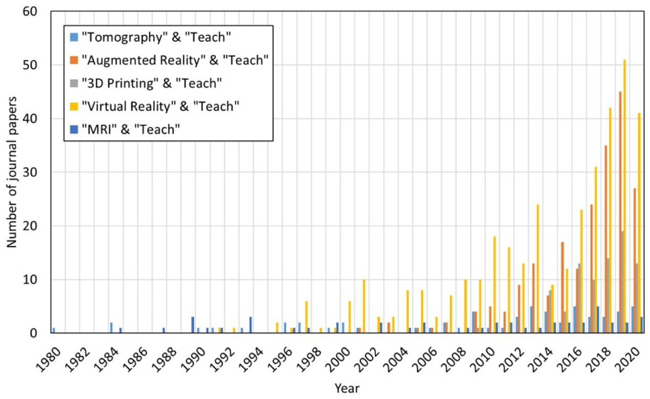
However, up to the present, it seems that the incorporation of computed tomography in teaching is much less than other technological advances such as augmented reality, 3D printing, or virtual reality. One of the ways of verifying this fact is to analyze how many scientific articles are published per year related to the use of new technologies in teaching. To this end, a bibliometric study was carried out. Figure 2 shows the number of papers published since 1980 related to the use of some of the latest technological developments (CT technology, Augmented Reality, 3D Printing, Virtual Reality, and Magnetic Resonance Imaging) in teaching. The data were obtained using the website Web of Science (Clarivate Analytics, Philadelphia, PA, USA).
The results show that, in recent years, the number of scientific publications has clearly increased. Figure 2 also shows that most of the articles show teaching experiences with augmented reality and virtual reality, and very few articles are related to teaching experiences with tomography.
Furthermore, as indicated above, the vast majority of articles related to the use of computed tomography in teaching show experiences in medical schools. The number of experiences in engineering fields is practically nil.

2. Research Objective

Concrete is the most widely used composite material in civil engineering. As in the rest of the modern composite materials, the understanding of the microstructure is very important to comprehend their macroscopic response. This experience can inspire other teachers from engineering schools to use the computed tomography as a teaching tool in their subjects about materials.
Certain technical concepts about concrete, especially those related to the microstructure and its macroscopic response, are difficult for students to assimilate, especially if they do not have the possibility of observing the microstructure of concrete with their own eyes.
At this point, the research question is how we can provide the student with the experience of observing the microstructure of concrete, so that it can be easier for them to understand those technical concepts related to its microstructure. In this sense, computed tomography could be a good tool.
The two main objectives of this research work were, firstly, to assess whether computed tomography is a good tool for the student to observe and better understand the microstructure of concrete and, secondly, if so, to determine to what extent the use of the computed tomography as a teaching tool improves the academic results about concrete in civil engineering students.
To this end, a pilot test was designed. This test consisted in performing a set of six practices, where the students discover and work with some aspects related to microstructure of concrete. The research objective of this pilot test was twofold. On the one hand, to evaluate the viability of these practices and, on the other hand, to analyze the teaching impact of this activity.
Other objectives of this research work were to evaluate how the practices using this new technology relate to the rest of the subject, and how the student values the incorporation of computed tomography in the studies.

3. Inclusion of Computed Tomography in the Teaching of Concrete Technology

In the degree of civil engineering, concrete technology is taught in several subjects, such as construction materials, reinforced concrete, advanced reinforced concrete, etc., and it is partially used in many others, such as construction procedures, bridge technology, etc. In all cases, around half of the teaching load is dedicated to practical classes. A part of them corresponds to practical laboratory classes. A small portion of these is dedicated to showing the students the experimental technique known as “computed tomography”. In this hands-on class, students learn some basic concepts of this technique and, under the supervision of the technician responsible of the CT-Scan device, they can see how the scanning of small structural concrete specimens is carried out.
From the pedagogical point of view, it is a very important activity, since it allows the students to become familiar with an experimental technique as innovative and with such projection as computed tomography.

4. Teaching Practices Related to the Use of Computed Tomography

Once the students have become familiar with the technique of computed tomography, they carry out a series of practices in which they study different concepts related to the microstructure of concrete, based on the information provided by computed tomography.
Next, some of the most interesting practices performed are shown. Due to time constraints in the subjects, it is not possible to carry out all the practices every year. These practices highlight the teaching possibilities of this experimental technique in the teaching of structural concrete.

4.1. Study of the Different Constituents of Concrete

At a microscopic level, concrete is a strongly heterogeneous material, composed of coarse aggregates, fine aggregates, a cementitious matrix that occupies the gaps between the aggregates, water bubbles, and pores.
The volumetric relationships between aggregates, cement paste, water, and pores have a strong influence on the macroscopic response of concrete. Thus, for example, when the volume of cement paste exceeds a certain minimum threshold, corresponding to the space between the coarse aggregate for a configuration of maximum compactness, the aggregates cease to be in contact and the interlocking between them is reduced, resulting in less rigidity of concrete. On the contrary, when the volume of paste is below this minimum threshold, pores appear between the cement paste.
In addition, the geometry of the coarse aggregate is of great importance in the behavior of concrete, both fresh and hardened. Thus, for example, when round aggregates from gravel pits (and therefore, with rounded edges and corners) are used, the interlocking between the aggregates is greatly reduced. The macroscopic result is that fresh concrete has greater fluidity, and hardened concrete, a lower modulus of elasticity. On the contrary, when crushing aggregate from quarries is used (and, therefore, with more-angular edges and corners), the bond between the aggregates is greater and the macroscopic behavior is clearly different.
Explaining all these concepts is not an easy task, especially if the students cannot observe them. In this sense, computed tomography is tremendously useful.
For this first teaching practice, computed tomography has previously been performed on a series of concrete test specimens (usually cubic or small cylindrical), with different dosages, that is, different volumetric ratio between the aggregate and the cement paste, and with different types of aggregate.
In this practice, the students must manipulate the three-dimensional images obtained from the scan, isolate the different components of the concrete, and observe and analyze the differences between them. To this end, they must use a digital image post-processing program. In this case, the free software IMAGEJ (developer National Institutes of Health, Stapleton, NY, USA) or the commercial software AVIZO (Thermo Fisher Scientific, Waltham, MA, USA) are usually used. In both cases, it is possible to identify and isolate the different phases that make up the concrete (Figure 3).
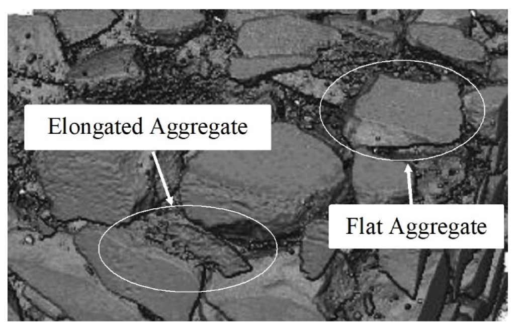
Another important aspect in relation to aggregates is the content of flat and elongated particles (Figure 4). This type of aggregate tends to break during concreting, alternating the mixture and causing a worse compaction of the concrete and a greater porosity.
The observation of this type of aggregate is very educational for the students, as it allows them to better understand this phenomenon.
The observation of the porosity of concrete is also very interesting. The first impression that the student has when explaining about the pores in concrete is that all of them show the same size and that they are spherical. However, this is not true, since as the phase is less dense and less rigid, it finally occupies the free space. Therefore, there are a multitude of sizes and shapes (Figure 5). In order to be easily identified, each pore is painted in a different color.
The teaching objective of this first practice is that the students can discover each one of the aspects mentioned above, such as, for example, observing the geometric and distribution characteristics of coarse aggregates, or pores.

4.2. Study of the Brittleness of High-Strength Concrete and Its Comparison with Conventional Concrete

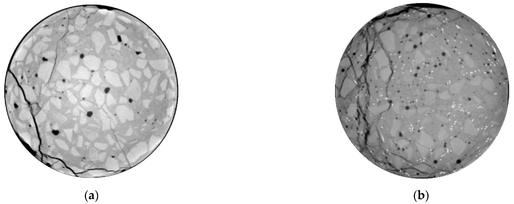
High-strength concrete is a concrete that presents a greater compressive strength than normal concrete. Its application is very widespread today, especially in singular structural elements, such as large bridges or skyscrapers. It has innumerable advantages, both from the point of view of mechanical behavior and durability. However, one of its disadvantages is that it shows a more fragile collapse. The explanation is that, when the concrete collapses, the cracks go through the aggregate, dissipating less energy during collapse. On the contrary, in conventional concretes, cracks surround the aggregate, dissipating more energy during collapse.
The observation of this behavior is very interesting from the teaching point of view, since it allows the students to better assimilate this concept and understand more clearly which are the design strategies in high-strength concrete, to eliminate its inherent fragility.
For this second teaching practice, computed tomography has been previously performed on two cylindrical concrete specimens, one of them of high-strength concrete and the other of normal concrete. Both specimens have been previously tested under monotonic compression until failure.
In this practice, the students have to identify the cracks and coarse aggregate and observe the different shape of cracks in both concrete specimens (Figure 6).
In summary, the teaching objective of this second practice is for students to be able to identify the different propagation patterns in high-strength concrete on one side and in normal concrete on the other side.

4.3. Study of the Evolution of Concrete Microstructure during Concrete Setting and Hardening

The microstructure of concrete does not remain immobile during setting and hardening, but evolves. The greatest evolution occurs with the pores, since in the first ages, they are full of water and, due to hydration, chemical reactions take place and the pores lose their water. During this process, the pores change in size and many of them collapse.
The observation of this process has great teaching value, since it allows the students to understand in a simple way some macroscopic phenomena of great interest, such as shrinkage by drying of concrete or plastic settlement in slabs.
For this third teaching practice, computed tomography has been previously performed on a cylindrical concrete specimen repeatedly during the first seven days of setting. In this case, the specimen is kept inside a PVC mold for the entire time. Therefore, the loss of water can only be produced by the upper face, which is the one in contact with the air.
In this practice, students must extract the pores and compare their evolution over time (Figure 7 and Figure 8).
This teaching practice specifically focuses on pores. Thus, for example, they can observe the spatial distribution of the pores, both in density and size. Students can evaluate how much smaller pores are near the top edge of the specimen, while inside they are larger. They also observe how the shrinkage causes part of the concrete to detach from the mold, leaving an empty space in that area. That is, they discover how shrinkage is a three-dimensional phenomenon and that it is associated with the loss of water during the setting and hardening of concrete.
In summary, the teaching objective of this third practice is for students to be able to analyze porosity in concrete along the depth.

4.4. Study of the Influence of Air-Void Agents on Concrete Microstructure

Concrete structures placed in regions with a high number of freeze–thaw cycles (such as the north of the USA and the south of Canada, or the north of China, etc.), are designed with a minimum threshold of air-voided content, to better withstand freeze–thaw cycles.
This is achieved using air-entraining agent (AEA), which is an additive to concrete that is incorporated into the concrete mass and it is able to generate small air bubbles that are finally trapped inside the concrete mass.
From the educational point of view, it is a very interesting concrete, since it is designed with a specific purpose: to better withstand freeze–thaw cycles.
Modern AEAs allow the generation of many small pores, thus improving the response to freeze–thaw cycles.
For this fourth teaching practice, computed tomography has previously been performed on a series of concrete specimens with different AEA contents (from 0.0% to 0.4% of AEA by volume). In this practice, students extract only the pores and compare the different specimens (Figure 9). Additionally, some basic statistical post-processing must be carried out to quantitatively compare the specimens.
This teaching practice complements the one previously described, since much more aspects about pores can be observed. Thus, for example, it can observe the spatial distribution of the pores, their quantity and shape, as a function of the AEA content. Observation allows the students to observe how an excess of AEA can have opposite effects to those desired.
In summary, the teaching objective of this fourth practice is for students to be able to analyze porosity in concrete from a more technological perspective.

4.5. Study of the Fiber Distribution and Orientation of Fiber-Reinforced Concrete

Fiber-reinforced concrete is a widely used structural solution of great engineering interest. It is an alternative solution to conventional reinforced concrete, in which the reinforcing bars are replaced, totally or partially, by fibers. In this case, the fibers support the tensile stresses, while the concrete supports the compressive stresses.
The main advantage of this structural solution is the reduction in labor in the manufacture of the concrete elements, since the fibers are added during the concreting process. However, this solution is more complex from a technological point of view.
Its structural response mainly depends on the morphological parameters and the distribution of the fibers within the concrete matrix. Aspects such as fiber content, length, thickness (or, in other words, slenderness), or distribution are basic aspects in the macroscopic response of fiber-reinforced concrete. Both fiber distribution and orientation are strongly random parameters, resulting in a macroscopic response with a higher degree of dispersion and uncertainty.
For this fifth teaching practice, computed tomography has previously been performed on several prismatic specimens of fiber-reinforced concrete. In some cases, the specimens have been extracted from larger structural elements in such a way that the dominant orientations of the fibers are clearly different. In this practice, students must extract only the fibers and observe their morphological parameters (Figure 10). To this end, students must develop some mathematical tools to help them to quantitatively compare the fibers.
This practice is the first introduction for the students into the study of fibers. Students can observe the different orientations of the fibers. On the other hand, the previously scanned specimens were flexibly tested under static or fatigue compression tests, measuring the compressive strength or the fatigue life, respectively. The student can compare how the different orientation of the fibers strongly conditions their mechanical response.
From the teaching point of view, this relationship is very revealing, since it allows the student to understand how the microstructure affects the macroscopic response.
In summary, the teaching objective of this fifth teaching practice is that students can become familiar with concrete with fibers and begin to understand how the morphological parameters and the orientation and distribution of the fibers affect the macroscopic response of concrete.

4.6. Study of the Failure Mechanisms of Fiber-Reinforced Concrete

As a continuation of the previous teaching practice, in this case it is proposed to study the failure mechanisms of fiber-reinforced concrete. In a similar way to what happens with reinforced concrete, the fibers are able to withstand tensile stresses because they are anchored to the cementitious matrix. When a concrete element is subjected to a load, cracks appear. Depending on the relative position between the cracks and the fibers, and also on the angle between the cracks and the fibers, the failure may be due to fiber breakage or anchorage failure.
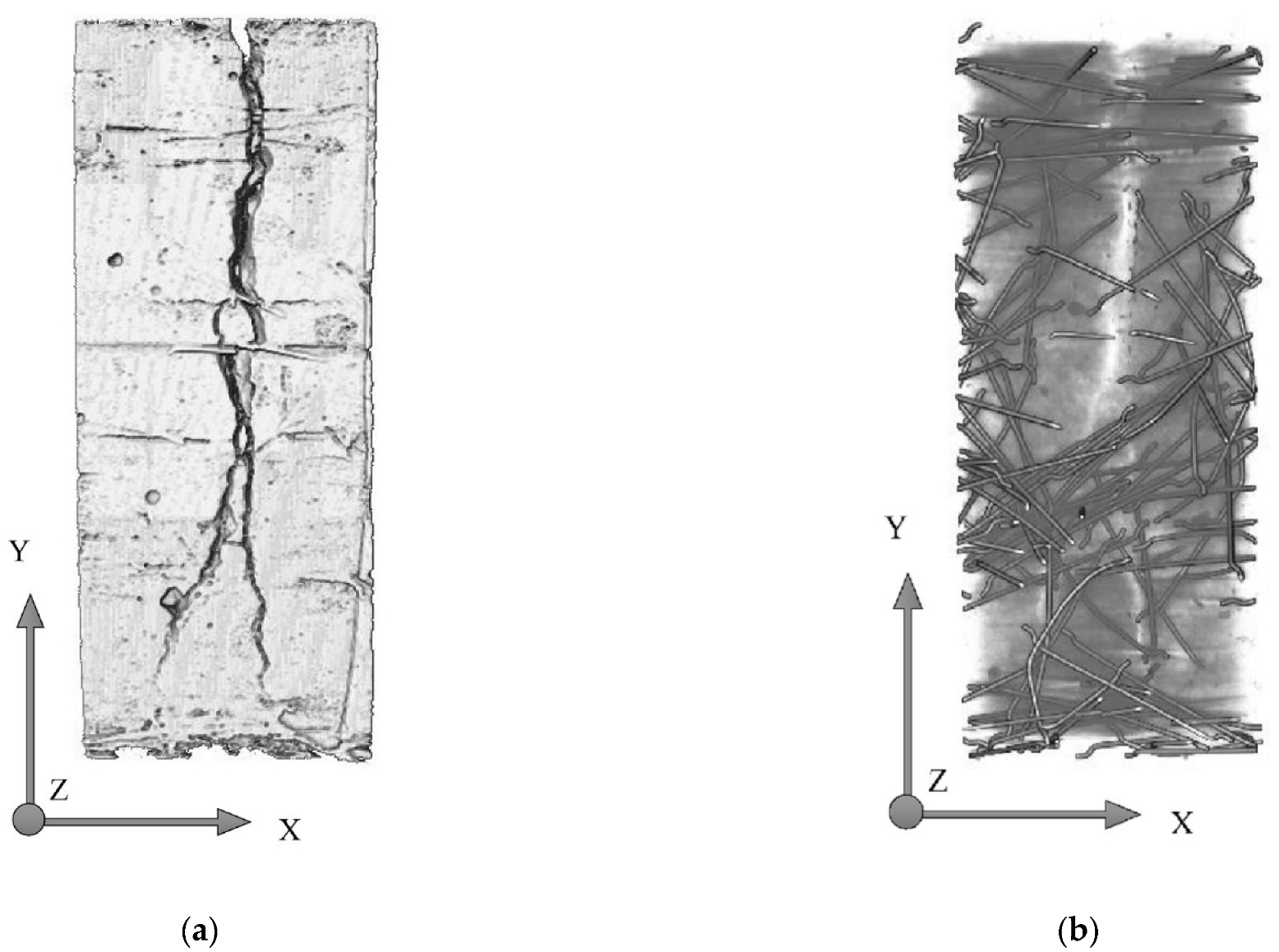
For this sixth teaching practice, computed tomography has been previously performed on several prismatic fiber-reinforced concrete specimens after having been subjected to a three-point bending test until failure. As in a previous teaching practice, these specimens have previously been extracted from a larger structural element in such a way that the dominant orientations of the fibers are clearly different. In this teaching practice, students have to extract and observe fibers and cracks (Figure 11).
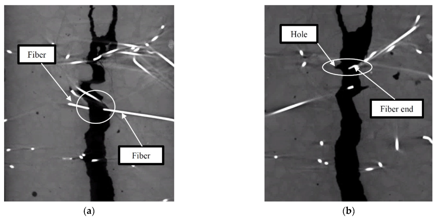
In this practice, the students have to identify the different types of failure, that is, failure by fiber breakage and failure by anchoring. Here, students will be able to observe how when the crack passes very close to the edge of a fiber, it tends to present an anchoring failure, while if the crack passes through the fiber through its central zone and, moreover, does so in a substantially perpendicular, the dominant failure is due to fiber breakage (Figure 12).
As in the previous teaching practice, the observations of these failure mechanisms are very enriching from the teaching point of view, since they allow the student to understand how the microstructure affects the macroscopic response.
As a summary, the teaching objective of this sixth practice is, for students, to be able to observe the different failure modes in fiber-reinforced concrete elements and to explore how the orientation and distribution of the fibers affect the macroscopic response of concrete elements.

5. Pilot Test

During the 2020–2021 academic year, a pilot test was carried out with a small group of students of the subject “Precast Concrete”, from which 11 students out of 38 students enrolled. The subject belongs to the fourth year of the Civil Engineering Degree at the University of Burgos. By the time of this study, all the students were familiar with the basic concepts of concrete technology, since they had passed subjects such as Introduction to Reinforced Concrete and Construction Procedures, among others. The students enrolled in this pilot test were identified as the “experimental group”, while the rest of the students, subjected to a traditional teaching methodology (conventional practical classes carried out on the blackboard), were identified as the “traditional group”. Students enrolled in this pilot test were randomly selected. These students also received the traditional teaching methodology, that is, they also received conventional practical classes carried out on the blackboard about topics other than concrete microstructure).
As explained before, the research objectives of this pilot test were to evaluate the viability of these practices and to analyze the teaching impact of this activity.
The complete project includes the six practices described above. The length of each of them is approximately 2 h. Students worked individually using the computer equipment provided by the university (in the faculty’s computer room) or they can use their own laptops.
The scans were carried out by the specialist technician of the tomography equipment and each student received a raw file with all the information generated by the computed tomography equipment.
At the beginning of the practice, each student received a small form with a series of questions to answer, related to the object of the practice. At the end, each student handed in the completed form to the teacher.
In order to evaluate the influence of the project on the students, a survey was carried out on all participating students. The survey consisted of 14 questions; the first six questions were related to the use of new technologies in teaching in general, and the next five questions were specifically related to the use of computed tomography for teaching issues. In addition, the last three questions were about their perception of the educational environment. This survey was conducted at the end of the pilot test.
The questions were written following the UWES (Utrecht Work Engagement Scale) [68]. Table 1 shows the survey.

6. Results

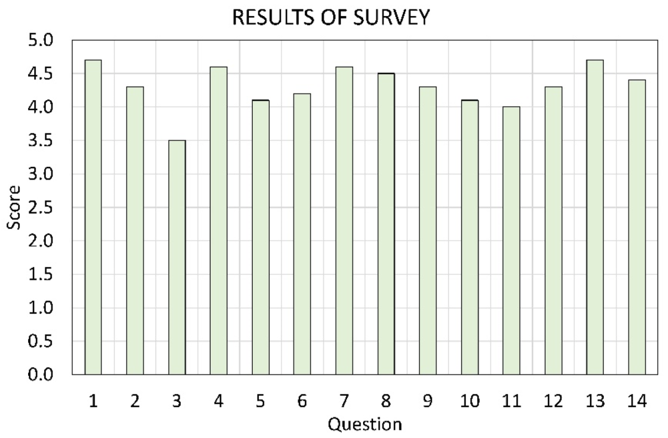
Next, the results of the survey (Figure 13) and a table including the main statistical results (Table 2) are shown.
The results obtained in this pilot test are very promising. First, the results of the survey reveal that the students consider very important the use of new technologies for teaching issues in civil engineering. All the questions reached a score above 4.0 (out of 5.0), except for question no. 3. In this case, students do not think that the practical classes on new technologies are more instructive than the conventional one. In fact, they consider that they are as instructive as the conventional one, and complementary.
Table 2 shows the mean and standard deviation values, both for the set of questions and for each of the three parts. The results show how the mean values are, in all cases, higher than 4.0. The highest result is obtained for the range of questions 12–14, that is, questions related to how students’ perception of their educational environment improves when new technologies are introduced in teaching.
One of the most interesting conclusions at this point is that students satisfactorily received the project. A greater motivation of students in the subject was also observed, which resulted in better grades when compared with those of previous courses.
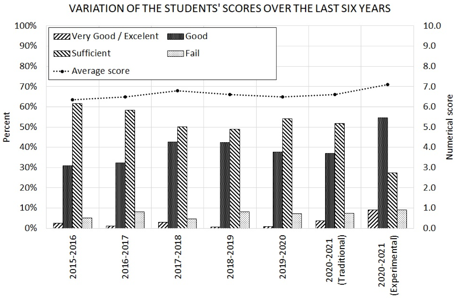
Figure 14 shows a comparison between the scores obtained by the students enrolled in the subject during the last six years (including the current academic year). This diagram includes the distribution of “Very Good/Excellent”, “Good”, “Sufficient”, and “Fail” over time (according to the European Credit Transfer and Accumulation System (ECTS)) and also the average score of the student (ranging from 0 to 10). In addition, for the year 2020–2021, both the score of the “experimental group” (i.e., the 11 students enrolled to this pilot test) and the “traditional group” (i.e., the rest of the students, subjected to the same traditional teaching methodology, equal to the one used in the previous years) are shown.
The results show how the incorporation of the teaching practices described in this paper improved the academic results of the students. Firstly, it is observed how the average grade of the students of the experimental group rose around 0.7 points (out of 10) with respect to the traditional group, and around 0.8 points (out of 10) with respect to the previous five years. Moreover, students with a “Very Good/Excellent” grade increased notably, rising from 3.7% in the traditional group to 9.1% in the experimental group. The percentage of students with a “Good” grade also increased, rising from 37% in the traditional group to 54.5% in the experimental group. In addition, in the 2020–2021 academic year, in the experimental group, the most common grade among students was “Good”, while in the traditional group and in the previous five years, the most common grade among students was “Sufficient”.
The results demonstrate that computed tomography is a useful tool for teaching purposes. This novel technology motivates students to study the microstructure of concrete and also facilitates them to understand it, improving their skills and knowledge in this field. The main consequence is a notable increase in the academic score of the students.

7. Conclusions

This paper shows the teaching experience of the authors in the use of computed tomography for teaching the subject of structural concrete in the studies of the degree of civil engineering.
In this case, the inclusion of computed tomography is carried out through six practical classes, in which students receive a series of previously scanned test specimens and work on different concepts related to the microstructure of concrete.
A pilot test was carried out to evaluate the viability of these practices and to analyze the teaching impact of this activity. The results show that students are very interested in the use of new technologies in teaching and, more particularly, in the use of computed tomography. From the teaching point of view, this learning project is very positive, since it allows students to visualize some concepts that are otherwise more difficult to understand. Furthermore, this knowledge is acquired in a more interactive environment, favoring students’ motivation and resulting in a remarkable improvement in their grades.
The comparison of the academic results between the students belonging to the experimental group and the traditional group reveals that the average grade of the students rose by around 0.7 points (out of 10). Similarly, the average score of the experimental group was around 0.8 points (out of 10) higher than the one obtained by the students in the previous five years.
Moreover, the percentage of students who achieved a “Very Good/Excellent” grade increased notably. In addition, the most common academic grade among students went from “Sufficient” (as in the previous five years) to “Good” in the experimental group.
Consequently, the pilot test reveals that computed tomography is a useful tool for teaching purposes, with high potential to help students to study and better understand the microstructure of concrete.

Author Contributions

Conceptualization and methodology M.A.V., J.M. and D.C.G.; teaching of the practice classes M.A.V., J.M. and D.C.G.; funding acquisition and project administration, M.A.V. and D.C.G.; writing—original draft preparation, D.C.G.; writing—reviewing and editing, M.A.V., J.M. and D.C.G. All authors have read and agreed to the published version of the manuscript.

Funding

This research was funded by the Ministerio de Economía y Competitividad, Gobierno de España (Spain); grant number PID2019-110928RB-C32.

Institutional Review Board Statement

The study was conducted according to the guidelines of the Declaration of Helsinki, and approved by the Institutional Review Board (or Ethics Committee) of University of Burgos (date of approval 17 June 2020).

Informed Consent Statement

Informed consent was obtained from all subjects involved in the study.

Conflicts of Interest

The authors declare no conflict of interest.

References

  1. Vuorikari, R.; Punie, Y.; Cabrera, M. Emerging Technologies and the Teaching Profession: Ethical and Pedagogical Considerations Based on Near-Future Scenarios; EUR 30129 EN; Publications Office of the European Union: Luxembourg, 2020. [Google Scholar]
  2. Sosa, E.A.; Salinas, J.; de Benito, B. Emerging technologies (ETs) in education: A systematic review of the literature published between 2006 and 2016. Int. J. Emerg. Technol. Learn. 2017, 12, 128–149. [Google Scholar] [CrossRef] [Green Version]
  3. Mussig, J.; Clark, A.; Hoermann, S.; Loporcaro, G.; Loporcaro, C.; Huber, T. Imparting Materials Science Knowledge in the Field of the Crystal Structure of Metals in Times of Online Teaching: A Novel Online Laboratory Teaching Concept with an Augmented Reality Application. J. Chem. Educ. 2020, 97, 2643–2650. [Google Scholar] [CrossRef]
  4. Carrera, C.C.; Asensio, L.A.B. Augmented reality as a digital teaching environment to develop spatial thinking. Cartogr. Geogr. Inf. Sci. 2017, 44, 259–270. [Google Scholar] [CrossRef]
  5. Turkan, Y.; Radkowski, R.; Karabulut-Ilgu, A.; Behzadan, A.H.; Chen, A. Mobile augmented reality for teaching structural analysis. Adv. Eng. Inform. 2017, 34, 90–100. [Google Scholar] [CrossRef]
  6. Redondo, E.; Fonseca, D.; Sanchez, A.; Navarro, I. New Strategies Using Handheld Augmented Reality and Mobile Learning-teaching Methodologies, in Architecture and Building Engineering degrees. 2013 International Conference on Virtual and Augmented Reality in Education. Procedia Comput. Sci. 2013, 25, 52–61. [Google Scholar] [CrossRef]
  7. Kysela, J.; Storkova, P. Using augmented reality as a medium for teaching history and tourism. International Conference on New Horizons in Education, INTE 2014. Procedia-Soc. Behav. Sci. 2015, 174, 926–931. [Google Scholar] [CrossRef] [Green Version]
  8. Dunleavy, M.; Dede, C.; Mitchell, R. Affordances and Limitations of Immersive Participatory Augmented Reality Simulations for Teaching and Learning. J. Sci. Educ. Technol. 2009, 18, 7–22. [Google Scholar] [CrossRef]
  9. Wei, X.D.; Weng, D.D.; Liu, Y.; Wang, Y.T. Teaching based on augmented reality for a technical creative design course. Comput. Educ. 2015, 81, 221–234. [Google Scholar] [CrossRef]
  10. Ye, Z.; Dun, A.S.; Jiang, H.M.; Nie, C.F.; Zhao, S.L.; Wang, T.; Zhai, J. The role of 3D printed models in the teaching of human anatomy: A systematic review and meta-analysis. BMC Med. Educ. 2020, 20, 335. [Google Scholar] [CrossRef]
  11. Kong, X.X.; Nie, L.Y.; Zhang, H.J.; Wang, Z.L.; Ye, Q.; Tang, L.; Huang, W.H.; Li, J.Y. Do 3D Printing Models Improve Anatomical Teaching about Hepatic Segments to Medical Students? A Randomized Controlled Study. World J. Surg. 2016, 40, 1969–1976. [Google Scholar] [CrossRef]
  12. McMenamin, P.G.; Quayle, M.R.; McHenry, C.R.; Adams, J.W. The Production of Anatomical Teaching Resources Using Three-Dimensional (3D) Printing Technology. Anat. Sci. Educ. 2014, 7, 479–486. [Google Scholar] [CrossRef] [PubMed]
  13. Scalfani, V.F.; Vaid, T.P. 3D Printed Molecules and Extended Solid Models for Teaching Symmetry and Point Groups. J. Chem. Educ. 2014, 91, 1174–1180. [Google Scholar] [CrossRef]
  14. Ford, S.; Minshall, T. Invited review article: Where and how 3D printing is used in teaching and education. Addit. Manuf. 2017, 25, 131–150. [Google Scholar] [CrossRef]
  15. Chong, S.; Pan, G.T.; Chin, J.K.; Show, P.L.; Yang, T.C.K.; Huang, C.M. Integration of 3D Printing and Industry 4.0 into Engineering Teaching. Sustainability 2018, 10, 3960. [Google Scholar] [CrossRef] [Green Version]
  16. Codd, A.M.; Choudhury, B. Virtual Reality Anatomy: Is it Comparable with Traditional Methods in the Teaching of Human Forearm Musculoskeletal Anatomy? Anat. Sci. Educ. 2011, 4, 119–125. [Google Scholar] [CrossRef]
  17. Josman, N.; Ben-Chaim, H.M.; Friedrich, S.; Weiss, P.L. Effectiveness of virtual reality for teaching street-crossing skills to children and adolescents with autism. Int. J. Disabil. Hum. Dev. 2008, 7, 49–56. [Google Scholar] [CrossRef]
  18. Gerson, L.B.; Van Dam, J. A prospective randomized trial comparing a virtual reality simulator to bedside teaching for training in sigmoidoscopy. Endoscopy 2003, 35, 569–575. [Google Scholar] [CrossRef] [Green Version]
  19. Ke, F.F.; Pachman, M.; Dai, Z.H. Investigating educational affordances of virtual reality for simulation-based teaching training with graduate teaching assistants. J. Comput. High. Educ. 2020, 32, 607–627. [Google Scholar] [CrossRef]
  20. Hoffman, H.; Vu, D. Virtual reality: Teaching tool of the twenty-first century. Acad. Med. 1997, 72, 1076–1081. [Google Scholar] [CrossRef]
  21. Chou, C.; Hsu, H.L.; Yao, Y.S. Construction of a virtual reality learning environment for teaching structural analysis. Comput. Appl. Eng. Educ. 1997, 5, 223–230. [Google Scholar] [CrossRef]
  22. Mayne, R.; Green, H. Virtual reality for teaching and learning in crime scene investigation. Sci. Justice 2020, 60, 466–472. [Google Scholar] [CrossRef]
  23. Wilhjelm, J.E.; Duun-Henriksen, J.; Hanson, L.G. A virtual scanner for teaching fundamental magnetic resonance in biomedical engineering. Comput. Appl. Eng. Educ. 2018, 26, 2197–2209. [Google Scholar] [CrossRef]
  24. Stawicki, S.P.; Grocias, V.H.; Schrag, S.P.; Martin, N.D.; Dean, A.J.; Hoey, B.A. The dead continue to teach the living: Examining the role of computed tomography and magnetic resonance imaging in the setting of postmortem examinations. J. Surg. Educ. 2008, 65, 200–205. [Google Scholar] [CrossRef] [PubMed]
  25. Hailey, D.M.; Crowe, B.L.; Burgess, I.A.; Khangure, M.S.; Morris, I. The effect of magnetic resonance imaging in a teaching hospital on patient management. Australas. Radiol. 1993, 37, 249–251. [Google Scholar] [CrossRef]
  26. Rundle, D.; Kishore, S.; Seshadri, S.; Wehrli, F. Magnetic resonance imaging simulator: A teaching tool for radiology. J. Digit. Imaging 1990, 3, 226–229. [Google Scholar] [CrossRef] [Green Version]
  27. Moheit, L.; Schmid, J.D.; Schmid, J.M.; Eser, M.; Marburg, S. Acoustics Apps: Interactive simulations for digital teaching and learning of acoustics. J. Acoust. Soc. Am. 2021, 149, 1175–1182. [Google Scholar] [CrossRef]
  28. Corral, E.; Gómez, M.J.; Ruiz, R.; Castejon, C.; García-Prada, J.C. Effects of an android app on mechanical engineering students. Comput. Appl. Eng. Educ. 2018, 26, 1050–1057. [Google Scholar] [CrossRef]
  29. Wojciechowski, R.; Cellary, W. Evaluation of learners’ attitude toward learning in ARIES augmented reality environments. Comput. Educ. 2013, 68, 570–585. [Google Scholar] [CrossRef]
  30. Yoon, S.A.; Elinich, K.; Wang, J.; Steinmeier, C.; Tucker, S. Using augmented reality and knowledge-building scaffolds to improve learning in a science museum. Int. J. Comput. -Supported Collab. Learn. 2012, 7, 519–541. [Google Scholar] [CrossRef]
  31. Ab Aziz, N.A.; Ab Aziz, K.; Paul, A.; Yusof, A.M.; Noor, N.S.M. Providing augmented reality based education for students with attention deficit hyperactive disorder via cloud computing: Its advantages. In Proceedings of the 2012 14th International Conference on Advanced Communication Technology (ICACT), PyeongChang, Korea, 19–22 February 2012; pp. 577–581. [Google Scholar]
  32. Sumadio, D.D.; Rambli, D.R.A. Preliminary Evaluation on User Acceptance of the Augmented Reality Use for Education. In Proceedings of the Second International Conference on Computer Engineering and Applications, Bali, Indonesia, 19–21 March 2010; pp. 461–465. [Google Scholar]
  33. Yuen, S.C.-Y.; Yaoyuneyong, G.; Johnson, E. Augmented Reality: An Overview and Five Directions for AR in Education. J. Educ. Technol. Dev. Exch. 2011, 4, 119–140. [Google Scholar] [CrossRef]
  34. Yilmaz, R.M.; Goktas, Y. Using augmented reality technology in storytelling activities: Examining elementary students’ narrative skill and creativity. Virtual Real. 2017, 21, 75–89. [Google Scholar] [CrossRef]
  35. Kirner, T.G.; Reis, F.M.V.; Kirner, C. Development of an interactive book with augmented reality for teaching and learning geometric shapes. In Proceedings of the 7th Iberian Conference on Information Systems and Technologies (CISTI 2012), Madrid, Spain, 20–23 June 2012; pp. 1–6. [Google Scholar]
  36. Vicente, M.A.; González, D.C.; Mínguez, J. Recent advances in the use of computed tomography in concrete technology and other engineering fields. Micron 2019, 118, 22–34. [Google Scholar] [CrossRef] [PubMed]
  37. Mena, A.; González, D.C.; Mínguez, J.; Vicente, M.A. Computed tomography beyond medicine: Applications to the microstructural study of concrete and other engineering materials. Hormigón Acero 2020, 71, 7–19. [Google Scholar]
  38. Seidelmann, F.E.; Reich, N.E. Computed tomography using the EMI scanner: Part I. The apparatus, the normal scan, and its variants. J. Am. Osteopath. Assoc. 1975, 74, 1125–1132. [Google Scholar]
  39. Watson, R.C. The whole body scan. Computed tomography (CT)—A major advance in the diagnosis of cancer. Clin. Bull. 1976, 6, 47–51. [Google Scholar]
  40. Jelden, G.L.; Chernak, E.S.; Rodriguez Antunez, A.; Haaga, J.R.; Lavik, P.S.; Dhaliwal, R.S. Further progress in CT scanning and computerized radiation-therapy treatment planning. Am. J. Roentgenol. 1976, 127, 179–185. [Google Scholar] [CrossRef] [Green Version]
  41. Jungers, W.L.; Minns, R.J. Computed tomography and biomechanical analysis of fossil long bones. Am. J. Phys. Anthropol. 1979, 50, 285–290. [Google Scholar] [CrossRef] [PubMed]
  42. Osti, F.; Santi, G.M.; Neri, M.; Liverani, A.; Frizziero, L.; Stilli, S.; Maredi, E.; Zarantonello, P.; Gallone, G.; Stallone, S.; et al. CT conversion workflow for intraoperative usage of bony models: From DICOM data to 3D printed models. Appl. Sci. 2019, 9, 708. [Google Scholar] [CrossRef] [Green Version]
  43. Notman, D.N.H.; Tashjian, J.; Aufderheide, A.C.; Cass, O.W.; Shane, O.C.; Berquist, T.H.; Gray, J.E.; Gedgaudas, E. Modern imaging and endoscopic biopsy techniques in Egyptian mummies. Am. J. Roentgenol. 1986, 146, 93–96. [Google Scholar] [CrossRef] [Green Version]
  44. Cheng, Q.; Zhang, X.; Guo, J.; Wang, B.; Lei, Y.; Zhou, G.; Fu, Y. Application of computed tomography in the analysis of glass beads unearthed in Shanpula cemetery (Khotan), Xinjiang Uyghur Autonomous Region. Archaeol. Anthropol. Sci. 2019, 11, 937–945. [Google Scholar] [CrossRef]
  45. Hilderbrand, B.; Harrington, T. Mapping of Materials Stress with Ultrasonic Tomography. In Proceedings of the DARPA/AFML Review of Progress in Quantitative NDE, La Jolla, CA, USA, 17–21 July 1978; p. 49. [Google Scholar]
  46. More, N.; Basse-Cathalinat, B.; Baquey, C.; Lacroix, F.; Ducassou, D. Application of novel techniques of medical imaging to the non-destructive analysis of carbon-carbon composite materials. Nucl. Instrum. Methods Phys. Res. 1983, 214, 531–536. [Google Scholar] [CrossRef]
  47. Kar, J.; Dinda, S.K.; Roy, G.G.; Roy, S.K.; Srirangam, P. X-ray tomography study on porosity in electron beam welded dissimilar copper–304SS joints. Vacuum 2018, 149, 200–206. [Google Scholar] [CrossRef] [Green Version]
  48. Yu, W.; Sing, S.L.; Chua, C.K.; Tian, X. Influence of re-melting on surface roughness and porosity of AlSi10Mg parts fabricated by selective laser melting. J. Alloys Compd. 2019, 792, 574–581. [Google Scholar] [CrossRef]
  49. Petrovic, A.M.; Siebert, J.E.; Rieke, P.E. Soil Bulk Density Analysis in Three Dimensions by Computed Tomographic Scanning. Soil Sci. Soc. Am. J. 1982, 46, 445–450. [Google Scholar] [CrossRef]
  50. Wang, G.; Jiang, C.; Shen, J.; Han, D.; Qin, X. Deformation and water transport behaviors study of heterogenous coal using CT-based 3D simulation. Int. J. Coal Geol. 2019, 211, 103204. [Google Scholar] [CrossRef]
  51. Morgan, I.L.; Ellinger, H.; Klinksiek, R.; Thomson, J.N. Examination of Concrete by Computerized Tomography. ACI J. Proc. 1980, 77, 23–27. [Google Scholar]
  52. Wang, Y.S.; Dai, J.G. X-ray computed tomography for pore-related characterization and simulation of cement mortar matrix. NDTE Int. 2017, 86, 28–35. [Google Scholar] [CrossRef]
  53. Vicente, M.A.; González, D.C.; Mínguez, J.; Tarifa, M.A.; Ruiz, G.; Hindi, R. Influence of the pore morphology of high strength concrete on its fatigue life. Int. J. Fatigue 2018, 112, 106–116. [Google Scholar] [CrossRef]
  54. Mínguez, J.; Vicente, M.A.; González, D.C. Pore morphology variation under ambient curing of plain and fiber-reinforced high performance mortar at an early age. Constr. Build. Mater. 2019, 198, 718–731. [Google Scholar] [CrossRef]
  55. Vicente, M.A.; Mínguez, J.; González, D.C. Computed tomography scanning of the internal microstructure, crack mechanisms, and structural behavior of fiber-reinforced concrete under static and cyclic bending tests. Int. J. Fatigue 2019, 121, 9–19. [Google Scholar] [CrossRef]
  56. Vicente, M.A.; Ruiz, G.; González, D.C.; Mínguez, J.; Tarifa, M.; Zhang, X. CT-Scan study of crack patterns of fiber-reinforced concrete loaded monotonically and under low-cycle fatigue. Int. J. Fatigue 2018, 114, 138–147. [Google Scholar] [CrossRef]
  57. Vicente, M.A.; Ruiz, G.; González, D.C.; Mínguez, J.; Tarifa, M.; Zhang, X. Effects of fiber orientation and content on the static and fatigue behavior of SFRC by using CT-Scan technology. Int. J. Fatigue 2019, 128, 105178. [Google Scholar] [CrossRef]
  58. Savoldi, F.; Yeung, A.W.K.; Tanaka, R.; Zadeh, L.M.S.; Montalvao, C.; Bornstein, M.M.; Tsoi, J.K.H. Dry Skulls and Cone Beam Computed Tomography (CBCT) for Teaching Orofacial Bone Anatomy to Undergraduate Dental Students. Anat. Sci. Educ. 2020, 14, 62–70. [Google Scholar] [CrossRef]
  59. Rutty, J.; Biggs, M.; Dowsett, D.; Kitchener, A.; Coltman, N.; Rutty, G. Post mortem computed tomography: An innovative tool for teaching anatomy within pre-registration nursing curricula. Nurse Educ. Today 2019, 76, 154–164. [Google Scholar] [CrossRef]
  60. Jaber, J.R.; Carrascosa, C.; Arencibia, A.; Corbera, J.A.; Ramirez, A.S.; Melian, C. 3-D computed tomography reconstruction: Another tool to teach anatomy in the veterinary colleges. Iran. J. Vet. Res. 2018, 19, 1–2. [Google Scholar]
  61. Murakami, T.; Tajika, Y.; Ueno, H.; Awata, S.; Hirasawa, S.; Sugimoto, M.; Kominato, Y.; Tsushima, Y.; Endo, K.; Yorifuji, H. An Integrated Teaching Method of Gross Anatomy and Computed Tomography Radiology. Anat. Sci. Educ. 2014, 7, 438–449. [Google Scholar] [CrossRef] [PubMed]
  62. Gagg, C.R. Cement and concrete as an engineering material: An historic appraisal and case study analysis. Eng. Fail. Anal. 2014, 40, 114–140. [Google Scholar] [CrossRef]
  63. Amirault, R.J. Distance learning in the 21st century University. Q. Rev. Distance Educ. 2012, 13, 253–265. [Google Scholar]
  64. Cassidy, E.D.; Colmenares, A.; Jones, G.; Manolovitz, T.; Shen, L.; Vieira, S. Higher Education and Emerging Technologies: Shifting Trends in Student Usage. J. Acad. Librariansh. 2014, 40, 124–133. [Google Scholar] [CrossRef]
  65. Gikas, J.; Grant, M.M. Mobile computing devices in higher education: Student perspectives on learning with cellphones, smartphones & social media. Internet High. Educ. 2013, 19, 18–26. [Google Scholar]
  66. Paul, J.A.; Cochran, J.D. Key interactions for online programs between faculty, students, technologies, and educational institutions: A holistic framework. Q. Rev. Distance Educ. 2013, 14, 49–62. [Google Scholar]
  67. Qasrawi, H. Optimal method for teaching concrete technology for civil engineering students. MOJ Civ. Eng. 2018, 4, 225–235. [Google Scholar] [CrossRef]
  68. Schaufeli, W.; Bakker, A. UWES. Utrecht Work Engagement Scale; Occupational Health Psychology Unit, Utrecht University: Utrecht, The Netherlands, 2004. [Google Scholar]
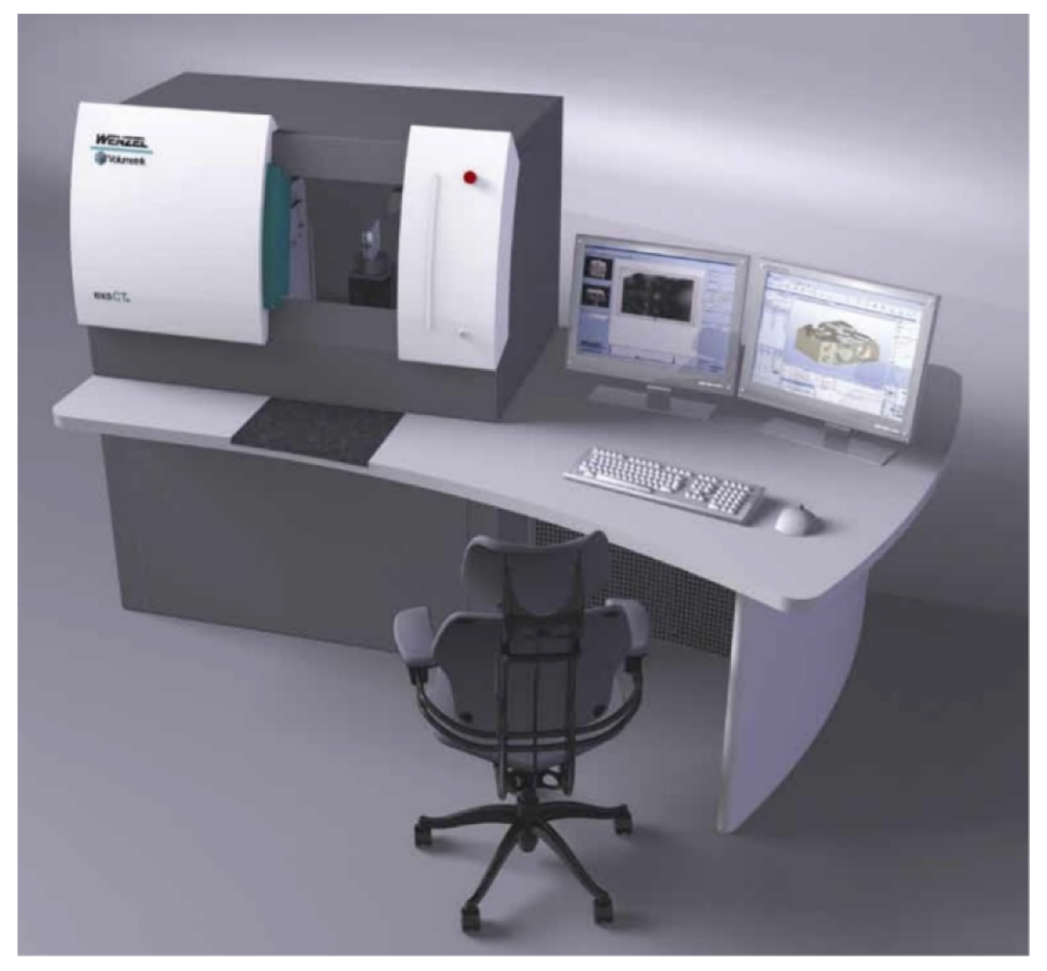
Figure 1. Example of Desktop CT-Scan, Courtesy of Wenzel Volumetrik (Hohentwiel, Germany).
Education 11 00768 g001
Figure 2. Increase in the number of scientific publications related to the teaching use of some of the most popular emerging technologies (1980–2020).
Education 11 00768 g002
Figure 3. Example of the different phases of concrete specimen. (a) The whole specimen, (b) the aggregates, (c) the pores, and (d) the fibers.
Education 11 00768 g003
Figure 4. Identification of flat aggregate and elongated aggregate.
Education 11 00768 g004
Figure 5. Detailed view of the pores inside a concrete specimen.
Education 11 00768 g005
Figure 6. Example of the different crack patterns in concrete specimens. (a) High-strength concrete and (b) normal concrete.
Education 11 00768 g006
Figure 7. Example of slices obtained from the CT-Scan device showing pore evolution over time. From left to right: 1, 2, 3, 4, and 7 days’ age.
Education 11 00768 g007
Figure 8. Example of pore evolution over time. From left to right: 1, 2, 3, 4, and 7 days age.
Education 11 00768 g008
Figure 9. Example of pore evolution over time. (ae): 0.0%, 0.1%, 0.2%, 0.3%, and 0.4% of AEA by volume.
Education 11 00768 g009
Figure 10. Example of concrete specimens with fibers. (a) Cubic specimen with long hooked-end fibers, (b) cylinder with small straight fibers, and (c) fibers segmentation.
Education 11 00768 g010
Figure 11. Example of a CT-Scan of the surrounding of a crack obtained through a three-point bending test. (a) The entire scan and (b) a detailed view of the crack and the fibers around it.
Education 11 00768 g011
Figure 12. Two examples of different fiber failure. (a) fiber breakage and (b) anchorage failure.
Education 11 00768 g012
Figure 13. Result of the survey.
Education 11 00768 g013
Figure 14. Variation of the students’ scores over the last six years.
Education 11 00768 g014
Table 1. Survey.
Table 1. Survey.
Please indicate your level of agreement with the following statement.
0 = Totally disagree
1 = Disagree
2 = Partially disagree
3 = Partially agree
4 = Agree
5 = Totally agree
1Incorporating new scientific advances into classes is motivating
2The practical classes on new technologies are more interesting
3The practical classes on new technologies are more instructive than the conventional ones
4The practical classes on new technologies are better for my professional future
5The subject is best learned when it is taught using new technologies
6Interest and motivation for the subject increases when new technologies are used for teaching
7Computed tomography is useful to understand the behavior of any material
8Computed tomography is useful to understand the behavior of concrete
9Using computed tomography, I better understand some aspects shown in the master classes
10Performing practical classes based on the results of computed tomography scans is good for my training
11Computed tomography helps me to interconnect concepts studied in other subjects
12Carrying out practical classes using new technologies improves my perception about the quality of my university
13Carrying out practical classes using new technologies improves my perception about the usefulness of my career
14Carrying out practical classes using new technologies improves the perception about the quality of the teachers of the subject
Table 2. Main statistical results of the survey.
Range of QuestionsMean ScoreStandard Deviation
1–144.310.32
1–64.230.43
7–114.300.25
12–144.470.21
Publisher’s Note: MDPI stays neutral with regard to jurisdictional claims in published maps and institutional affiliations.