Article

A Novel In Vitro Simulator to Investigate Promotion of Reconstruction of Damaged Neuronal Cell Colony Differentiated from iPS Cells with the Aid of Micro Dynamic Stimulation

1
Graduate School of Science and Engineering, Yamagata University, 4-3-16 Jonan, Yonezawa 992-8510, Yamagata, Japan
2
YOKOWO Co., Ltd., 1112 Kanohara, Tomioka 370-2495, Gunma, Japan
3
School of Medicine, Yamagata University, 2-2-2 Iida-nishi, Yamagata 990-9585, Yamagata, Japan
*
Author to whom correspondence should be addressed.
Technologies 2021, 9(4), 83; https://doi.org/10.3390/technologies9040083
Submission received: 27 September 2021 / Revised: 1 November 2021 / Accepted: 2 November 2021 / Published: 4 November 2021

Abstract

:
Neuronal cells are equipped with the function of a sensor that senses stimulation and elongates neurites to connect nearby neuronal cells in forming a neuronal network, as they are generally said to be hard to recover from physical damage, such as in the case of a spinal cord injury. Therefore, in this study, a novel in vitro simulator in which micro dynamic stimulations are applied to a damaged neuronal cell colony artificially is proposed to investigate the possibility of promoting the reconstruction of damaged neuronal cells on a colony basis. A neuronal cell colony differentiated from iPS cells is physically damaged by cutting off treatment, and micro dynamic stimulations are applied to the colony by utilizing a developed mini-vibration table system. NeuroFluor NeuO is used to establish a method for fluorescent staining of the living neuronal cells, and morphologies of the reconstructing neurons are analysed, revealing a relationship between the stimulation and the reconstructing process of the damaged neurons. It is found that significant differences are observed in the reconstructing efficiency between the statically cultured damaged neuronal cell colony and the dynamically stimulated one. The results suggest that applying appropriate micro dynamic stimulations is a promising approach to promote the reconstruction of a damaged neuronal cell colony.

Graphical Abstract

1. Introduction

In clinical treatment of neuronal medicine, various types of neuronal cells are reconstructed or transplanted into patients who suffer severe neuronal diseases or injuries such as Amyotrophic Lateral Sclerosis (ALS) [1], Parkinson’s disease [2,3] and spinal cord injury [4,5,6,7,8]. In the case of spinal cord injury, for example, reconstruction of the damaged neuronal cells colony might be carried out first if the damage is not so severe. On the other hand, in the future, regenerative medicine using pluripotency of stem cells will be a probable way to determine whether the damage severe to such an extent that the spinal cord is totally snapped off. Through the cellular reprogramming technique, by using four transcription factors Oct3/4, Sox2, Klf4, c-Myc, induced pluripotent stem (iPS) cells have been developed [9,10,11] that possess inherent properties to proliferate infinitely while retaining the ability to differentiate into almost any type of cell. Regenerative medicine is in currently in a phase of rapid development and the engraftment of transplanted neuronal cells, as well as the reconstruction of the neuronal network, will become the most important issue. In both cases it is strongly needed to develop new approaches or device systems to support these medical treatments technically, as well as to promote efficiency and quickness of the treatments.
Several studies have reported that well-controlled dynamic stimulations are able to promote abilities of cell proliferation, growth and recovery from damage [12,13,14,15,16,17]. Likewise, the appropriate mechanical stimulations may have the potential to raise the efficiency and speed of the differentiation of the iPS cells into the objective cells. Limited research reports have been published so far about the relationship between mechanical stimulations and cellular differentiation of rat pheochromocytoma (PC12), embryonic stem (ES) cells or iPS cells [18,19,20,21,22,23,24]. Rapid progresses in microelectromechanical systems (MEMS) to manipulate minute living cells, and in advanced materials to be used for scaffold in three-dimensional cellular culturing provide a novel method to approach various sciences and technologies related to iPS cells [25,26]. Effects of low frequency (10–40 Hz), low magnitude vibrations in the differentiation of stem cells have recently been reported, stating that low frequency, low magnitude vibrations are sufficient to induce or to promote mesenchymal stem cells into neural cells [27,28,29].
In view of the circumstances, in this study, a novel in vitro simulator in which micro dynamic stimulations are applied to an artificially damaged neuronal cell colony is proposed in order to investigate the possibility of promoting the reconstruction of a damaged neuronal cell colony. Firstly, a cantilever-type piezoelectric mini-vibration table, which enables us to impose various micro dynamic stimulations directly onto the cultured adhesive cells or cellular colonies on culture dish set inside the incubator, is developed together with an in vitro seeding-damage-reconstruction device. Secondly, in order to verify the ability of the developed system, dynamic stimulations are applied to a damaged mouse neuronal cell colony. The neuronal cells differentiated from mouse iPS cells are cultured for 5 days, and after the cells have grown sufficiently, the neuronal cell colony with neurites are physically damaged by cutting off treatment. Micro dynamic stimulations by using the developed mini-vibration table are applied for 6 days after the cutting damage, while NeuroFluor NeuO(STEMCELL Technologies) is used to conduct fluorescent staining of the living neuronal cells. Thirdly, effects of the dynamic stimulations on the reconstructing process of the damaged neuronal cells are investigated by analysing the immunostained areas of the living neuronal cell colony with or without dynamic stimulations. The parameters of reconstruction efficiency as well as the extensibility of reconstructed neurites are newly proposed in order to achieve quantitative analysis about the possibility of promoting the reconstruction of a damaged neuronal cell colony.

2. Materials and Methods

2.1. Development of Mini-Vibration Table

Figure 1a shows the practical construction of the proposed mini-vibration table which is designed based on the following analysis. Basically, vibrator of the table is made from one metal strip (stainless steel, 120 mm length × 6 mm width × 0.4 mm thickness as typical dimensions). Bi-morph type piezoelectric excitation is used utilizing piezoelectric elements (or PZTs) bonded on both side of the vibrator, where each side consists of four 6.0 × 3.0 × 0.2 mm PZTs (C-213, Fuji Ceramics, Shizuoka-ken, Japan) side by side. One end of the vibrator is rigidly clamped by two brass blocks. A culture dish with a 35 mm inner diameter is supposed to be mounted on triangular Aluminium support on the other free end of the vibrator. When voltage was applied to the PZTs on the vibrator, the inverse piezoelectric effect of the PZT bends the vibrator. This bending deformation causes the vibratory movement of the free end of the vibrator, as shown with a red arc in Figure 1a. Figure 1c shows the real view of the developed mini-vibration table with a cell culture dish on its free end. As shown in Figure 1b, by using the signal output function of the FFT analyser and an amplifier (NF Electric Instruments, HSA4012, Yokohama, Japan), a continuous sine wave is generated and applied to the PZTs of the vibration table. The cells in a culture dish mounted on the vibration table are stimulated dynamically with a given frequency, amplitude and direction. Eight such vibration tables can be set inside a conventional CO2 incubator after appropriate sterilization treatment. Practically, these eight vibration tables are electrically connected to the FFT analyser through a specially developed switching hub and are operated independently.
The above vibration table system is approximately modelled as a cantilever beam with a concentrated mass at its free end. Equation of motion of transverse vibration of beam [30] is given as
2 w t 2 + E I ρ A 4 w x 4 = 0
where w(x,t), E, I, A, ρ are transverse displacement, Young’s modulus, moment of inertia, cross-sectional area, and density of the beam, respectively, with distance x from the clamped edge and time t. The boundary conditions for this case are
w ( 0 , t ) = 0 ,       w ( 0 , t ) x = 0 ,     2 w ( l , t ) x 2 = 0 ,         E I 3 w ( l , t ) x 3 = m 2 w ( l , t ) t 2
where l is length of the beam, m is representative mass of the culture dish and its support at free end of the beam. Solving Equation (1) under the boundary conditions (2) yields following transcendental frequency Equation
1 + cos α l cos h α l + m ρ A l α l ( cos α l sin h α l sin α l cos h α l ) = 0
The natural frequency f [Hz] of the vibration table is given by the following Equation
f = ( α l ) 2 2 π l 2 E I ρ A     ,     α 2 = ρ A E I ω
where α l is a root of the frequency Equation (3) with circular frequency ω . The displacement of the table part is expressed by the following equation provided that the harmonic vibration is excited
w = a sin ( ω t + ϕ ) , ω = 2 π f  
where a, ϕ are amplitude of displacement and phase angle, respectively. Then, the acceleration of the table part is calculated as follows
w ¨ = a ω 2 sin ( ω t + ϕ )
where a ω 2 is the maximum acceleration of the table part.
Since the developed vibration table is a simple cantilever structure, stable large displacement can easily be achieved by adjusting the span of the vibrator, as seen in Figure 1c. Additionally, by rotating the culture dish, any direction of two-dimensional dynamic stimulation can be enforced to the cells cultured on the dish. Furthermore, natural frequencies can easily be sifted by adjusting the length l of the vibrator. In this study, stable vibrations in a horizontal direction are realized in condition with total amplitude up to 60 μm and frequency up to 12 Hz due to electro-mechanical ability of the device system.

2.2. Cell Preparations

In this study, mouse iPS cells (Cell No. APS0001, Cell name: iPS-MEF-Ng-20D-17, Lot No. 013) [9] are purchased from RIKEN Cell Bank and used in all experiments. The iPS cells are maintained in undifferentiated state when cultured in the presence of the SNL76/7 STO feeder cell [31] layer. The SNL76/7 STO cells are cultured in KnockOut DMEM (Dulbecco’s Modified Eagle Medium, Invitrogen, Waltham, MA, USA) + 2 mM Glutamine (nacalai tesque) + 10% FBS (foetal bovine serum, Lot No. A70109-1732 (standard quality)) + 1% antibiotic substance (penicillin streptomycin solution stabilized, SIGMA-Aldrich, St. Louis, MO, USA). The SNL76/7 STO cells are treated with 10 µg/mL Mitomycin C Solution (nacalai tesque) for 2 h. Then, the cells are washed with PBS twice and are replated on 0.1% gelatin coated tissue culture dishes at a density of 5.4 × 10⁵ cells/dish. The mouse iPS cells provided for the experiment are seeded on the SNL76/7 STO feeder cells at a density of 5 × 10⁵ cell/dish with D-MEM (Dulbecco’s Modified Eagle Medium, Wako, Osaka, Japan) + 15% FBS + 1% NEAA (Non-Essential Amino Acids, invitrogen) + 1% antibiotic substance + 10−4 M 2-Mercaptoethanol(Lot No. 2268B111, COSMO BIO Co., Tokyo, Japan) + 1000 U/mL LIF (Leukaemia Inhibitory Factor, MILLIPORE, Burlington, MA, USA), and are cultured in a CO2 incubator (temperature: 37 °C, humidity: 100% and 5% CO2 + 95% air). The culture medium is changed every 24 h. After 3 days of incubation, the iPS cell colonies are detached from the feeder cells by using Trypsin-EDTA solution (SIGMA) and are provided for the following differentiation process.
In this study, the SFEBq culture method (Serum-free Floating culture of Embryoid Body-like aggregates with quick reaggregation) [32] is used in neural differentiation process of the mouse iPS cells. The fundamental procedure of the differentiation can be divided into two main stages. In the first stage, the mouse iPS cells are induced into neural progenitor cells in suspension culture with G-MEM (Glasgow Minimum Essential Medium) + 10% KSR (Knockout Serum Replacement, Invitrogen) + 1% antibiotic substance + 2 × 10⁻³ M glutamine + 1 × 10⁻³ M sodium pyruvate (Invitrogen) + 0.1 × 10⁻³ M NEAA + 0.1 × 10⁻³ M 2-Mercaptoethanol. The cells are seeded on non-treated dishes at a density of 6 × 10⁵ cells/dish and are cultured in a CO2 incubator (temperature: 37 °C, humidity: 100%, 5% CO2 + 95% air) for five days. The neural differentiation process begins with separating the iPS cell colony from the feeder cells. Once the iPS cell colony detaches from the feeder cells, aggregation of the iPS cells in suspension initiates the differentiation.
Even if the feeder cells remain partially, these can be removed each time by transferring spherical aggregates of the floating iPS cells to a new culture dish, since the feeder cells need to attach to the culture dish. Thus, any contamination of the feeder cells can be avoided in the following adhesion culture of the cells. Then, in the second stage, the neural progenitor cells are induced into neurons in adhesion culture with the above-mentioned medium plus 1 × 10⁴ M all-trans-Retinoic Acid (Wako). This time the cells are seeded on four 2% Matrigel (FALCON)-coated dishes [33,34] and are cultured in the CO2 incubator (temperature: 37 °C, humidity: 100%, 5% CO2 + 95% air) for another four days. Main procedure of differentiation from mouse iPS cells into motor neurons is shown in Figure 2a together with a typical picture of the cell colony taken by a phase-contrast microscope.
Among the neurons, optical neurons, sensory neurons and motor neurons are well known. It is reported that motor neurons uniquely carry a motor neuron-specific transcription factor HB9 [35,36]. Therefore, as shown in Figure 2b, an additional experiment of immunostaining the HB9 by using Mouse Anti-MNR2 antibody (Developmental Studies Hybridoma Bank, Iowa City, IA, USA) is conducted in order to confirm what kind of neurons are induced in the above differentiation process, and it is confirmed that the present differentiated neurons are positive for HB9 staining and mostly identified as the motor neurons.

2.3. In-Vitro Seeding-Damage-Reconstruction System for Neuronal Cell Colony

The reconstruction experiment of the damaged neuronal cell colony is conducted as follows. Fluorescent staining of the damaged neuronal cell colony in reconstructing process is realized by using NeuroFluor NeuO (STEMCELL Technologies, Vancouver, BC, Canada), which has the remarkable ability to stain living neurons without fixation, and that the fluorescent image is continually observed under inverted phase-contrast microscope throughout the experiments. The proposed in vitro seeding-damage- reconstruction device is shown in Figure 3, while the detailed procedures are schematically explained in Figure 4 and Figure 5, and are summarized as follows:
(1) Retractable twin plates (A, B) system with guide structure is constructed inside the φ35 culture dish as seen in Figure 3a,c. The plate A is equipped with 2.0 × 3.0 × 1.7 mm seeding pit together with 0.5 × 0.5 × 0.3 mm guide tunnel in its lower side as shown in Figure 3b.
(2) After appropriate sterilization treatment using UV light exposure, 2% Matrigel coating is carried out on the surface of the culture dish.
(3) At day 0, the above-mentioned adhesion culture medium of 2 mL is dispensed on the culture dish and then the neural progenitor cell colony is seeded at a density of around 103 cells/colony inside the seeding pit under plate A, as shown in Figure 4a. The size of the colony is set as constant as possible. The seeded cell colony is easy to adhere at an appropriate point by the support of plate B. Three hours later, the experiment starts provided that the cells adhesion to the culture dish is confirmed. Delicate cell manipulations are carried out inside the isothermal chamber (Olympus IBMU and IBML which are installed on inverted phase-contrast microscope (Olympus, IX71, Shinjuku-ku, Japan)), of which the inner environment is kept at a temperature of 37 °C and CO2 at 5%, so that the cultured cells are kept in a normal condition during the experiment.
(4) At day 2, after the culture medium is aspirated out, plate B is removed so that the neurites are able to sprout freely to the right-hand direction, then a new culture medium is dispensed. Hereafter, the culture medium is changed every 48 h.
(5) At day 5, fluorescent stained images using 0.1% NeuroFluor NeuO are observed under an inverted phase-contrast microscope (Olympus, IX83) with excitation light of 488 nm wavelength. Then, cutting-off damage is conducted as the neuronal cell colony is severed by using a cell-scraper along the right-hand side edge line of plate A, as shown in Figure 4c,d. It is important to conduct the cutting operation smoothly by paying attention not to harm the Matrigel coat surface of the culture dish. After the cutting operation, the culture dish is kept untouched for three hours so that the cell adhesion becomes stable. From day 5, micro dynamic stimulations (vibration total amplitude: 60 µm, frequency: 5 Hz, 12 h. interval) using the mini-vibration table set inside CO2 incubator are applied as schematically described in Figure 5. On the other hand, static case (culture without the stimulations) is continued to culture in the completely same environment.
(6) At day 7 and day 9, reconstructing features of the damaged neuronal cell colony are observed by fluorescent stained images by using NeuroFluor NeuO without fixation of the cells.
(7) Finally, at day 11, immunostaining treatment is conducted by using Mouse Anti-βⅢ-tubulin antibody (R&D Systems, Minneapolis, MN, USA) with fixation of the cells. The cells are fixed by 4% paraformaldehyde phosphate-buffered solution (Wako Pure Chemical Industries, Ltd., Osaka, Japan) for 20 min, then are permeabilized with 0.3% Triton X-100 (Amersham Biosciences, Amersham, UK) + PBS for 5 min at room temperature. For the βⅢ-tubulin staining, the cells are incubated with Mouse Anti-βⅢ-tubulin antibody at 4 °C in darkness for 12 h. Then, the cells are further reacted with a 0.2% Alexa Fluor 488 goat anti-mouse IgG antibody (Invitrogen) for 60 min at room temperature. Then, fluorescent stained images through βⅢ-tubulin, which is uniquely carried by neurons, are observed under the phase-contrast microscope (Olympus, IX83) with excitation light of 488 nm wavelength.

3. Results

Effects of the dynamic stimulations on reconstructing process of the damaged neuronal cell colony differentiated from iPS cells are estimated by measuring the immunostained areas of the neural cells with or without the micro dynamic stimulations by utilizing the developed vibration table. In the results shown in the following Figures 7 and 10, differences between the dynamically stimulated case and the static case (control, i.e., at 0 Hz) are statistically analysed by t-test and are considered to be significant when the probability, p value, is less than 5 percent.
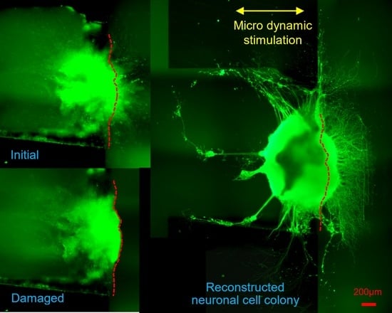
Figure 6 shows immunostained images of the in vitro reconstructing process of the damaged neuronal cell colony. Left side figures are the static case (control, without micro dynamic stimulation) for comparison. Right side figures are the case under micro dynamic stimulation (vibration total amplitude: 60 µm, frequency: 5 Hz, 12 h. interval). The reason why frequency of 5 Hz is used in this experiment is that it is most effective in differentiation and growth of mouse iPS cells into neurons as found by our previous study [23]. Figure 6a–d are stained fluorescent image by NeuroFluor NeuO, which has a remarkable ability to stain living neurons without fixation, and that the fluorescent image is continually observed under phase-contrast microscope throughout the experiments. As for Figure 6e, on the other hand, βⅢ-tubulin is stained after fixation of the cell colony in order to obtain a stable and clear image. It is clearly confirmed that neurites are sprouted around the seeding pit. Figures in green show direct fluorescent microscopic images with a dotted red line, which shows the approximate cutting line given from (b). The right end side figures in red show binarized images of the lost area (Alost in (a)) or the reconstructed area (Areconst. in (c), (d), (e)) in case of micro dynamic stimulation by utilizing WinROOF (scale bars = 200 µm). Furthermore, the yellow arrow in Figure 6c–e shows the direction of vibration stimulation by utilizing the developed mini-vibration table. Figure 6a shows the image just before cutting damage was made at day 5. Figure 6b shows the state immediately after the cutting damage (day 5), while the dotted red line shows the approximate cutting line. Black shadowy line behind the red cutting line shows the right-side edge of the Plate A explained in Figure 4. Figure 6c shows the initial reconstructing state (day 7 or 2 days after cutting damage) Neuronal reconstruction around the damaged boundary is gradually taking place by sprouting neurites in several points. Figure 6d shows the middle of reconstructing process (day 9 or 4 days after cutting damage) where reconstructed neurites are growing almost evenly and densely. Figure 6e shows the reconstructed final image in this series of experiment (day 11 or 6 days after cutting damage) where neurites are dramatically grown in numbers, density and length, especially in direction to the right-hand along with the cutting edge. This seems prominent in case under the micro dynamic stimulation.
Figure 7 shows a comparison of reconstruction efficiency Areconst./Alost (computed area ratio from Figure 6) of the damaged neuronal cell colony between the statically cultured neurons and the dynamically stimulated ones (vibration total amplitude: 60 µm, frequency: 5 Hz, 12 h. interval) with respect to culture time after the cutting damage operation. The reconstruction efficiency increases with increasing culture time as 7, 9 and 11 days (or, 2, 4 and 6 days after cutting damage) in the stimulation cases, while the situation is not observed in the static cases. In all three cases, the reconstruction efficiency of the dynamically stimulated cases is prominently higher than that of the static ones. Significant differences are observed between the statically cultured damaged neurons and the dynamically stimulated ones as the culture time increases, such as 9 to 11 days (or 4 to 6 days after the cutting damage). At day 11 (6 days after cutting damage), it is found that the reconstructed area from the cutting damage is up to around 80% in the dynamically stimulated case, while the area is almost unchanged with culture days and shows around 25% in the static case.
Figure 8 shows the relationship between the increase rate of reconstruction efficiency Areconst./Alost against the static case and the culture time. Y-axis is normalized reconstruction efficiency (stimulation/static) calculated from the results shown in Figure 7. The increase rate of reconstruction efficiency increases exponentially as the culture time increases, such as 7, 9, 11 days (or, 2, 4 and 6 days after cutting damage). The increase rate is the highest in the day 11 with about 241%, while it is about 96% in the day 7. It is found that the more the culture time after the cutting damage increases, the more the increase rate of reconstruction efficiency increases dramatically. This suggests that not only imposing the dynamic stimulation but also having appropriate culture time should be key factors to promote the reconstruction of damaged neuronal cell colony.
Figure 9 shows definition of parameters for evaluation of extensibility of reconstructed neurites of the colony [=(Em/Elost all) × 100] based on the typical binarized immunostained images which is treated by utilizing image analyser software WinROOf, Image J and Octave. Figure 9a shows definition of Llost_max: maximum straight-line length of neuron colony measured from edge line of the cutting damage to the furthest front line of the lost neurites, while Elost all: number of all pixels of the lost area of neurons Alost. Figure 9b shows parameters Lm and Em defined on the reconstructed neurons colony. The parameter Lm = (m/100) × Llost_max shows the location line until which the neuronal pixels are counted for from the line of cutting damage, with m = 100 coincide with Llost_max. The parameter Em is the number of neuronal pixels existing on the right side of line Lm on reconstructed neurites of the colony.
Figure 10 shows the effect of dynamic stimulation (vibration amplitude: 60 µm, frequency: 5 Hz, 12 h. interval) upon extensibility of the reconstructed neurites [=(Em/Elost all) × 100] with respect to the value of m (indicating location line up to which the neuronal pixels are counted for) as well as the culture time. Results are computed based on the parameters defined in Figure 9. At day 5 (Figure 10a), extensibilities of the statically cultured damaged neurons and the dynamically stimulated ones almost coincide with each other, since these are the initial state, i.e., just before the cutting damage. In Figure 10b–d, significant differences are observed between the statically cultured damaged neurons and the dynamically stimulated ones as the culture time increases, such as day 7, 9, 11, respectively (or 2, 4, 6 days after cutting damage). Especially, at day 11 (or 6 days after cutting damage), it is found that significant differences are observed in the cases with lower m such as m = 15~35, which correspond to comparatively proximal area to the cutting damage line. Furthermore, at day 11, maximum value of m in the stimulated cases reaches up to 110, which implies that reconstructed neurites finally surpass the initial length: Llost_max. (straight-line length measuring from the line of cutting damage to the front line). Thus, it is confirmed that the dynamic stimulation promotes reconstruction and extension of neurites within the damaged neuronal cell colony.
Figure 11 shows the effect of culture time after cutting damage upon the extensibility of reconstructed neurites [=(Em/Elost all) × 100] in the static case (a) and the dynamically stimulated (vibration amplitude: 60 µm, frequency: 5 Hz, 12 h. interval) case (b). Basically, figure axis and each data are the same as those given in Figure 10. On day 7, the extensibility of the reconstructed neurites in the dynamically stimulated case (Figure 11b) is far below compared to the initial state which is the state immediately before the cutting damage. However, the extensibility gradually increases as the culture time increases in order of 7, 9, 11 days (or 2, 4, 6 days after cutting damage), and reaches closer to the initial state. On the other hand, in the static case (Figure 11a), the extensibility does not increase systematically or stably as the culture time increases in order of 7, 9, 11, and it is not clear whether the extensibility is closer to the initial state or not, as the culture time increases. Especially, on the day 11, in the lower area of m, such as 0 to 22 which is the proximal area to the cutting damage, the extensibility is far below compared to the case of day 9.

4. Discussion

It has been pointed out that neuronal cells are equipped with the function of a sensor that senses physical or chemical stimulations and elongates neurites in appropriate directions to connect nearby neuronal cells in forming a network [37], while the cells are generally said to be hard to recover from major physical damage where the cell body or main neurites are almost severed completely. However, in the case of neuronal cell colony differentiated from iPS cells with appropriate size and environment [7,8], neurites might newly sprout from near-by undamaged neuronal cells within the colony. By avoiding the damaged neurons or their remains, some of the newly sprouted neurites will have the ability to make a connection between the damaged host neurons and the target neurons, similar to rewiring activity taking place in the spinal cord injury [4,5]. The immunostained images of the in vitro reconstructing process of the damaged neuronal cell colony shown in Figure 6c–e of this study imply the above possibility. Especially, Figure 6e shows how the reconstructing activity takes place around the damaged edge area of the neuronal cell colony. It is notable that an abundant thick bundle of neurites are sprouted from the right-hand side periphery of the cell colony and these construct a complex and dense neurites network. On the other hand, these phenomena are not seen in other un-damaged edge areas of the colony.
In spinal cord injury, it has been pointed out that three cases are likely to try to rewire the partly injured spine [5]. The first case is to promote axonal regeneration or direct endogenous reconnection, and the second one is to have axonal sprouting or indirect endogenous reconnection. The third case is to conduct neural stem cell transplantation and that to promote indirect exogenous reconnection, which will be valid even in the fully damaged spine. In the first two approaches, activation of damaged axon as well as neuron itself will likely be key factor for regenerating the damaged axons and following successful endogenous reconnection. Therefore, it is indispensable to develop techniques and devices to promote axonal regeneration and axonal sprouting.
Regenerative medicine, on the other hand, is currently in a phase of rapid development where the engraftment of transplanted neuronal cells as well as the reconstruction of neuron networks are becoming the most important issues to be solved. In both cases, henceforth, it is strongly needed to develop new approaches or device systems to support these medical treatments technically, as well as to promote efficiency and quickness of the treatments. In practical cases, various electric massagers embedded in bags, pillows, sofas, beds, etc. in which electric vibrators are utilized might become simple and possible candidates to apply the dynamic stimulations to the patient who has been under the clinical regenerative treatments, provided that appropriate technical adjustments and medical monitoring are carefully conducted.
In Figure 7, it is found that the reconstruction efficiency increases with increasing culture time, such as in 7, 9 and 11 days (or, 2, 4 and 6 days after cutting damage) in the stimulation cases. Furthermore, the increase rate of the reconstruction efficiency also increases with elapsed culture time as shown in Figure 8. On the other hand, in the static cases, the reconstruction efficiency is almost unchanged with increasing culture time as 7, 9 and 11 days. This implies that an important fact for the neuronal cell colony reconstruction from the cutting damage such that the appropriately controlled dynamic stimulation is indispensable to initiate the reconstruction process. However, the biochemical and molecular mechanism of the reconstruction phenomena of the damaged neuronal cells has not been elucidated thoroughly [4,5,6,7,8]. In this study, the neurons used are directly differentiated from iPS cells and that undamaged neurons near-by damaged area in the neuronal cell colony might intrinsically retain better ability in neurites sprouting and growth compared to spontaneously grown neuronal cell colony.
In Figure 10 and Figure 11, it is observed that the extensibility of the reconstructed neurites in the dynamically stimulated case is gradually increases as the culture time increases in the order of 7, 9, 11 days (or 2, 4, 6 days after cutting damage), and is getting closer to the initial state (the state immediately before the cutting damage), while the phenomenon does not explicitly occur in the static case. This means that the appropriately controlled dynamic stimulation is quite effective and stable to promote the extensibility of the reconstructed neurites from the damage. It is considered that the sensors of neuronal cells detect the vibration stimulation and translate it into chemical or electrical signals, and these might be transferred to neuronal cell growth cones leading stable neurites sprouting.
The results obtained in this study suggest various opportunities to develop effective reconstruction strategies of neurites from the physical damage. Namely, it is confirmed that the appropriate dynamic stimulation (or in other words dynamic stress) even as µm order amplitude vibration (acceleration is computed as 3.0 × 10⁻³ G from Equation (6)) is a promising approach to promote reconstruction of the damaged neuronal cell colony. The method can possibly provide a supporting measure in clinical treatment for the damaged neurons in cases such as spinal cord injury, in which a huge scientific and medical challenge to restore lost functions is still towering.
In the future, a more realistic and comprehensive in vitro simulator should be developed to meet serious and urgent clinical needs, for instance, in spinal cord injuries. In order to achieve this goal, firstly, it is necessary to identify the optimal condition of the directionality, the frequency, the magnitude, the timing, and the duration time of the applied dynamic stimulations to promote the reconstruction of the damaged neuronal cell colony. Secondly, a human neuronal cell colony should be used instead of the mouse one, although the differentiation time from human iPS cells into neuronal cells is required 30 to 40 days and its process is much more complicated. Thirdly, the present in vitro simulator system should be expanded in a three-dimensional culture environment in order to realize more actual conditions of the spinal cord injury. One promising candidate for this challenge might be the incorporation of gel-embedded three-dimensional culture [24]. Finally, neuroelectric reactions between the reconstructed neurons and nearby target neurons should be examined to confirm not only structural reconstruction but also functional reconstruction as a neuronal network.

5. Conclusions

In this study, a novel in vitro simulator which is able to apply micro dynamic stimulations onto a damaged neuronal cell colony differentiated from iPS cells is developed in order to investigate neuronal repair and regeneration. By using the system, as a first step, influence of the dynamic stimulations on the promotion of the reconstruction process of the neuronal cell colony from the damage is investigated. Newly proposed parameters for the reconstruction efficiency as well as the extensibility of reconstructed neurites are used for the evaluation of the present method. The results can be summarized as follows.
(1) Applying dynamic stimulations by utilizing a developed mini-vibration table together with an in vitro seeding-damage-reconstruction device and time dependent fluorescent staining observations by using NeuroFluor NeuO are able to provide a novel method to simulate ongoing reconstruction process of the damaged neuronal cell colony;
(2) It is found that significant differences are observed in the reconstruction efficiency: Areconst./Alost between the statically cultured damaged neuronal cell colony and the dynamically stimulated one as the culture time increasing such as 4 to 6 days after cutting damage operation;
(3) The extensibility of the reconstructed neurites [=(Em/Elost all)×100] in the dynamically stimulated case is gradually increasing as the culture time increasing in the order of 2, 4, 6 days after cutting damage operation and is getting closer to the initial state, while it does not explicitly occur in the static case;
(4) It is confirmed that applying appropriate micro dynamic stimulations is a promising approach to promote the reconstruction of the damaged neuronal cell colony, and that the present in vitro simulator system could possibly provide some fundamental information as a simple disease model for the spinal cord injury.

Author Contributions

The authors confirm contribution to the paper as follows: study conceptualization and design, T.K. (Tadashi Kosawada); methodology and data collection, T.K. (Tadashi Kosawada), T.K. (Taku Kitsunai), K.G.; analysis and interpretation of results, T.K. (Tadashi Kosawada), T.K. (Taku Kitsunai), Z.F.; draft manuscript preparation, T.K. (Tadashi Kosawada), T.K. (Taku Kitsunai); funding acquision, T.K. (Tadashi Kosawada), Z.F., K.G. All authors have read and agreed to the published version of the manuscript.

Funding

This research was funded in part by research grants from Grant-in-Aid for Scientific Research, Japan Society for the Promotion of Science, Nos. 15K13894, 16H04289 and 19H02089.

Institutional Review Board Statement

Not applicable.

Informed Consent Statement

Not applicable.

Data Availability Statement

The dataset generated or analyzed during the present study are available from the corresponding author on reasonable request.

Acknowledgments

The mouse iPS cells (Cell No. APS0001, Cell name: iPS-MEF-Ng-20D-17) was purchased from the RIKEN BRC through the Project for Realization of Regenerative Medicine and the National Bio-Resource Project of the MEXT, Japan.

Conflicts of Interest

The authors declare that they have no conflict of interest, financial or otherwise to report regarding the present study.

Ethics Approval

All experiments in this study are under approval of the Ethics Review Board of the Yamagata University (Yamagata, Japan).

References

  1. Chaddah, M.R.; Dickie, B.G.; Lyall, D.; Marshall, C.J.; Ben Sykes, J.; Bruijn, L.I. Meeting report of the International Consortium of Stem Cell Networks’ Workshop Towards Clinical Trials Using Stem Cells for Amyotrophic Lateral Sclerosis/Motor Neuron Disease. Amyotroph. Lateral Scler. 2011, 12, 315–317. [Google Scholar] [CrossRef] [PubMed]
  2. Cooper, O.; Hallett, P.; Isacson, O. Using stem cells and iPS cells to discover new treatments for Parkinson’s disease. Parkinsonism Relat. Disord. 2012, 18 (Suppl. 1), S14–S16. [Google Scholar] [CrossRef] [Green Version]
  3. Kikuchi, T.; Morizane, A.; Doi, D.; Magotani, H.; Onoe, H.; Hayashi, T.; Mizuma, H.; Takara, S.; Takahashi, R.; Inoue, H.; et al. Human iPS cell-derived dopaminergic neurons function in a primate Parkinson’s disease model. Nature 2017, 548, 592–596. [Google Scholar] [CrossRef] [PubMed]
  4. Dell’Anno, M.T.; Strittmatter, S.M. Rewiring the spinal cord: Direct and indirect strategies. Neurosci. Lett. 2017, 652, 25–34. [Google Scholar] [CrossRef]
  5. Zhu, Y.; Uezono, N.; Yasui, T.; Nakashima, K. Neural stem cell therapy aiming at better functional recovery after spinal cord injury. Dev. Dyn. 2018, 247, 75–84. [Google Scholar] [CrossRef] [PubMed] [Green Version]
  6. Tran, A.P.; Warren, P.M.; Silver, J. The biology of regeneration failure and success after spinal cord injury. Physiol. Rev. 2018, 98, 881–917. [Google Scholar] [CrossRef] [PubMed]
  7. Assinck, P.; Duncan, G.J.; Hilton, B.J.; Plemel, J.R.; Tetzlaff, W. Cell transplantation therapy for spinal cord injury. Nat. Neurosci. 2017, 20, 637–647. [Google Scholar] [CrossRef] [PubMed]
  8. Silva, D.; Sousa, R.A.; Salgado, A.J. Hydrogels as delivery systems for spinal cord injury regeneration. Mater. Today Bio. 2021, 9, 100093. [Google Scholar] [CrossRef] [PubMed]
  9. Okita, K.; Ichisaka, T.; Yamanaka, S. Generation of germline-competent induced pluripotent stem cells. Nature 2007, 448, 313–317. [Google Scholar] [CrossRef] [PubMed]
  10. Takahashi, K.; Tanabe, K.; Ohnuki, M.; Narita, M.; Ichisaka, T.; Tomoda, K.; Yamanaka, S. Induction of Pluripotent Stem Cells from Adult Human Fibroblasts by Defined Factors. Cell 2007, 131, 153. [Google Scholar] [CrossRef] [PubMed] [Green Version]
  11. Nakagawa, M.; Koyanagi, M.; Tanabe, K.; Takahashi, K.; Ichisaka, T.; Aoi, T.; Okita, K.; Mochiduki, Y.; Takizawa, N.; Yamanaka, S. Generation of induced pluripotent stem cells without Myc from mouse and human fibroblasts. Nat. Biotechnol. 2008, 26, 101–106. [Google Scholar] [CrossRef] [PubMed]
  12. Rosenberg, N.; Levy, M.; Francis, M. Experimental model for stimulation of cultured human osteoblast-like cells by high frequency vibration. Cytotechnology 2002, 39, 125–130. [Google Scholar] [CrossRef] [PubMed]
  13. Konno, K.; Kosawada, T.; Akutsu, M. Three-dimensional micro actuator and sensor system for dynamic stimulations and evaluations of mechanical properties of minute living cells. J. Biomech. Sci. Eng. 2006, 1, 147–158. [Google Scholar] [CrossRef] [Green Version]
  14. Konno, K.; Kosawada, T.; Suzuki, M.; Nakamura, T.; Feng, Z.; Yasukazu Hozumi, Y.; Goto, K. Dynamic actuation and sensing micro-device for mechanical response of cultured adhesive cells. Microsyst. Technol. 2010, 16, 993–1000. [Google Scholar] [CrossRef]
  15. Suter, D.M.; Miller, K.E. The emerging role of forces in axonal elongation. Prog. Neurobiol. 2011, 94, 91–101. [Google Scholar] [CrossRef] [PubMed] [Green Version]
  16. Ahmed, W.W.; Rajagopalan, J.; Tofangchi, A.; Saif, T.A. Neuromechanics: The Role of Tension in Neuronal Growth and Memory. Nano Cell Mech. 2013, 35–61. [Google Scholar] [CrossRef]
  17. Nagai, Y.; Yokoi, H.; Kaihara, K.; Naruse, K. The mechanical stimulation of cells in 3D culture within a self-assembling peptide hydrogel. Biomaterials 2012, 33, 1044–1051. [Google Scholar] [CrossRef] [PubMed] [Green Version]
  18. Ito, Y.; Kimura, T.; Nam, K.; Katoh, A.; Masuzawa, T.; Kishida, A. Effects of Vibration on Differentiation of Cultured PC12 Cells. Biotechnol. Bioeng. 2011, 108, 592–599. [Google Scholar] [CrossRef] [PubMed]
  19. Kuo, Y.C.; Huang, M.J. Material-driven differentiation of induced pluripotent stem cells in neuron growth factor-grafted poly (ε-caprolactone)-poly (β-hydroxybutyraye) scaffolds. Biomaterials 2012, 33, 5672–5682. [Google Scholar] [CrossRef] [PubMed]
  20. Teramura, T.; Takehara, T.; Onodera, Y.; Nakagawa, K.; Hamanishi, C.; Fukuda, K. Mechanical stimulation of cyclic tensile strain induces reduction of pluripotent related gene expressions via activation of Rho/ROCK and subsequent decreasing of AKT phosphorylation in human induced pluripotent stem cells. Biochem. Biophys. Res. Commun. 2012, 417, 836–841. [Google Scholar] [CrossRef]
  21. Horiuchi, R.; Akimoto, T.; Hong, Z.; Ushida, T. Cyclic mechanical strain maintains Nanog expression through PI3K/Akt signaling in mouse embryonic stem cells. Exp. Cell Res. 2012, 318, 1726–1732. [Google Scholar] [CrossRef]
  22. Khayat, G.; Rosenzweig, D.H.; Quinn, T.M. Low frequency mechanical stimulation inhibits adipogenic differentiation of C3H10T1/2 mesenchymal stem cells. Differentiation 2012, 83, 179–184. [Google Scholar] [CrossRef]
  23. Kosawada, T.; Koizumi, T.; Ugajin, K.; Feng, Z.; Goto, K. Novel Three-dimensional Micro Vibration Actuator for Imposing Dynamic Stimulations to Promote Differentiation of iPS Cells. Microsyst. Technol. 2016, 22, 45–56. [Google Scholar] [CrossRef]
  24. Kosawada, T.; Ohnishi, K.; Satoh, H.; Feng, Z.; Goto, K. Novel Methods to Apply Micro Dynamic Stimulations on Cultured Adhesive Cells and Its Application in Constructing Gel-embedded Three-dimensional Neuronal Structures Differentiated From Human iPS Cells. Microsyst. Technol. 2018, 24, 625–638. [Google Scholar] [CrossRef]
  25. Le Marchand, S.J.; Dalva, M.B. New imaging tools to study synaptogenesis. Cell. Migr. Form. Neuronal Connect. 2013, 2, 599–622. [Google Scholar]
  26. Edwards, J.H.; Reilly, G.C. Vibration stimuli and the differentiation of musculoskeletal progenitor cells: Review of results in vitro and in vivo. World J. Stem Cells 2015, 7, 568–582. [Google Scholar] [CrossRef] [PubMed]
  27. Cho, H.; Seo, Y.K.; Jeon, S.; Yoon, H.H.; Choi, Y.K.; Park, J.K. Neural differentiation of umbilical cord mesenchymal stem cells by sub-sonic vibration. Life Sci. 2012, 90, 591–599. [Google Scholar] [CrossRef] [PubMed]
  28. Choi, Y.K.; Cho, H.; Seo, Y.K.; Yoon, H.H.; Park, J.K. Stimulation of sub-sonic vibration promotes the differentiation of adipose tissue-derived mesenchymal stem cells into neural cells. Life Sci. 2012, 91, 329–337. [Google Scholar] [CrossRef]
  29. Marycz, K.; Lewandowski, D.; Tomaszewski, K.A.; Henry, B.M.; Golec, E.B.; Maredziak, M. Low-frequency, low-magnitude vibrations (LFLM) enhances chondrogenic differentiation potential of human adipose derived mesenchymal stromal stem cells (hASCs). PeerJ 2016, 4, e1637. [Google Scholar] [CrossRef] [Green Version]
  30. Timoshenko, S.; Young, D.H.; Weaver, J.R.W. Vibration Problems in Engineering, 4th ed.; John Wiley & Sons: Hoboken, NJ, USA, 1974; pp. 415–420. [Google Scholar]
  31. Pan, C.; Hicks, A.; Guan, X.; Chen, H.; Bishop, C.E. SNL fibroblast feeder layers support derivation and maintenance of human induced pluripotent stem cells. J. Genet. Genomics 2010, 37, 241–248. [Google Scholar] [CrossRef] [Green Version]
  32. Kamiya, D.; Banno, S.; Sasai, N.; Ohgushi, M.; Inomata, H.; Watanabe, K.; Kawada, M.; Yakura, R.; Kiyonari, H.; Nakao, K.; et al. Intrinsic transition of embryonic stem-cell differentiation into neural progenitors. Nature 2011, 470, 503–509. [Google Scholar] [CrossRef] [PubMed]
  33. Ma, W.; Tavakoli, T.; Derby, E.; Serebryakova, Y.; Rao, M.S.; Mattson, M.P. Cell-extracellular matrix interactions regulate neural differentiation of human embryonic stem cells. BMC Dev. Biol. 2008, 8, 13. [Google Scholar] [CrossRef] [PubMed] [Green Version]
  34. Dottori, M.; Pebay, A.; Pera, M.F. Neural Differentiation of Human Embryonic Stem Cells. In Neural Stem Cells; Humana Press: Totowa, NJ, USA, 2010; pp. 75–86. [Google Scholar]
  35. Hu, B.; Zhang, S.-C. Differentiation of spinal motor neurons from pluripotent human stem cells. Nat. Protoc. 2009, 4, 1295–1304. [Google Scholar] [CrossRef]
  36. Hu, B.; Zhang, S.-C. Directed differentiation of neural-stem cells and subtype-specific neurons from hESCs. Methods Mol. Biol. 2010, 636, 123–137. [Google Scholar]
  37. Tessier-Lavigne, M.; Goodman, C.S. The Molecular Biology of Axon Guidance. Science 1996, 274, 1123–1133. [Google Scholar] [CrossRef] [PubMed] [Green Version]
Figure 1. (a): Construction schematic of developed simple mini-vibration table by using bi-morph piezoelectric elements. (b): Control system of the mini-vibration table set inside CO2 incubator. (c): Typical real view of the developed mini-vibration table with cell culture dish on its free end.
Technologies 09 00083 g001
Figure 2. (a): Differentiation procedures from mouse iPS cells into motor neurons. By way of motor neuron progenitor cells, motor neurons are formed, and neurites start to sprout from the colony in all directions after about 10 days. (b): Typical differentiating mouse neuronal cell colony (at Day 8) from iPS cells. Left side figure: Light phase-contrast micrograph. Right side figure: Stained image of HB9 the motor neuron-specific transcription factor by using Mouse Anti-MNR2 antibody. The stained image is observed under the phase-contrast microscope with excitation light of 546 nm wavelength. Cell body of the motor neuron is coloured in red. It is confirmed that the differentiated neuronal cells are positive for HB9 staining. (Scale bars = 100 µm).
Technologies 09 00083 g002
Figure 3. In vitro seeding-damage-reconstruction device. Retractable twin plates (A, B) built in culture dish to be used for the reconstruction experiments of the damaged neuronal cell colony. (a) Construction schematic of the system. (b) Details of plate A and its 2.0 × 3.0 × 1.7 mm seeding pit and 0.5 × 0.5 × 0.3 mm guide tunnel. (c) Real view of the developed system built in the ϕ 35 culture dish.
Technologies 09 00083 g003
Figure 4. Schematic diagram of reconstruction experiments of the damaged neuronal cell colony by utilizing the developed system shown in Figure 3. (a) A neuronal cell colony is seeded at Day 0. (b) Plate B is removed at Day 2. (c,d) Cutting off damage is conducted at Day 5. (e) Reconstructed neurites are sprouting at Day 7–11.
Technologies 09 00083 g004
Figure 5. Experimental time scheme of reconstructing culture procedures of damaged neuronal cell colony by applying 12 h. Intermittent dynamic stimulations (vibration total amplitude: 60 µm, frequency: 5 Hz, 12 h. interval) for 6 days along with completely static case for comparison.
Technologies 09 00083 g005
Figure 6. Immunostained images of the in vitro reconstructing process of a damaged neuronal cell colony. Left side figures are the static case (control, without micro dynamic stimulation) for comparison. Right side figures are the case under micro dynamic stimulation (vibration total amplitude: 60µm, frequency: 5 Hz, 12 h. interval). (ad) are stained by NeuroFluor NeuO, while (e) by βIII-tubulin. Figures in green show direct microscopic images. The right end figures in red show area presumed to be cut off and lost: Alost. (a), or reconstructed area: Areconst. (ce). These are binarized images by utilizing WinROOF in case of micro dynamic stimulation. The dotted red line shows the approximate cutting line which is given from (b), and the yellow arrow shows the direction of vibration stimulation. (a): Just before cutting damage is conducted (day 5). (b): Immediately after cutting damage (day 5). (c): Initial reconstructing process (day 7 or 2 days after cutting damage). (d): Middle of the reconstructing process (day 9 or 4 days after cutting). (e): Reconstructed final image (day 11 or 6 days after cutting). It is clearly seen that neurites are sprouted around the seeding pit. Reconstructed neurites are dramatically sprouted to the right-hand direction, especially in a micro dynamic stimulation case. (scale bars = 200 µm).
Technologies 09 00083 g006aTechnologies 09 00083 g006b
Figure 7. Comparison of reconstruction efficiency Areconst./Alost of the damaged neuronal cell colony between the statically cultured neurons and the dynamically stimulated ones (vibration amplitude: 60 µm, frequency: 5 Hz, 12 h. interval) with respect to culture time according to the computed area from Figure 6. Significant differences are observed between the statically cultured damaged neurons and the dynamically stimulated ones as the culture time increases, such as 4 to 6 days after cutting damage operation.
Technologies 09 00083 g007
Figure 8. Relationship between the increased rate of reconstruction efficiency Areconst./Alost and the culture time. Y-axis is normalized reconstruction efficiency (stimulation/static) calculated from the results shown in Figure 7.
Technologies 09 00083 g008
Figure 9. Definitions of parameters for the evaluation of extensibility of the reconstructed neurites of the colony [=(Em/Elost all) × 100] based on the typical binarized immunostained images. The value of m indicates the location line up to which the neuronal pixels are counted for, with m = 100 coinciding with Llost_max., while Em is the number of neuronal pixels existing on the right side of line Lm defined on reconstructed neurites of the colony after the cutting damage. (a) Definition of Llost_max:maximum straight-line length of neuron colony measured from edge line of the cutting damage to the furthest front line of the lost neurons; (b) Lm and Em defined on reconstructed neuron network.
Technologies 09 00083 g009
Figure 10. Effect of dynamic stimulation (vibration amplitude: 60 µm, frequency: 5 Hz, 12 h. interval) upon extensibility of the reconstructed neurites [=(Em/Elost all) × 100] with respect to the value of m (indicating location line until which the neuronal pixels are counted for) and the culture time. Results are computed based on the parameters defined in Figure 9. Significant differences are observed between the statically cultured damaged neurons and the dynamically stimulated ones as the culture time increases, such as on day 7, 9, 11 (or 2, 4, 6 days after cutting damage), respectively. (a) Day 5 (initial state, just before cutting damage); (b) Day 7 (2 days after cutting damage); (c) Day 9 (4 days after cutting damage); (d) Day 11 (6 days after cutting damage).
Technologies 09 00083 g010aTechnologies 09 00083 g010b
Figure 11. Effect of culture time after cutting damage upon extensibility of reconstructed neurites [=(Em/Elost all) × 100] in the static case (a) and the dynamically stimulated (vibration amplitude: 60 µm, frequency: 5 Hz, 12 h. interval) case (b). The extensibility of the reconstructed neurites in the dynamically stimulated case gradually increases as the culture time increases in the order of 7, 9, 11 days (or 2, 4, 6 days after cutting damage), and reaches closer to the initial state. (a) Static case (n = 6); (b) Dynamically stimulated case (n = 6).
Technologies 09 00083 g011
Publisher’s Note: MDPI stays neutral with regard to jurisdictional claims in published maps and institutional affiliations.

