2.1. Sensing Glove
The sensing glove adopted in this work is made of cotton–lycra, and has three textile goniometers directly attached to the fabric.
Figure 2a shows the position of the goniometers on the glove, while
Figure 2b show the final prototype of the glove where the goniometers are insulated with an additional layer of black fabric.
The textile goniometers are double layer angular sensors, as previously described in [
14,
15]. The sensing layers are
knitted piezoresistive fabrics (KPF) that are made of 75% electro-conductive yarn and 25% Lycra [
16,
17]. The two KPF layers are coupled through an electrically-insulating stratum (
Figure 3a). The sensor output is the electrical resistance difference (ΔR) of the two sensing layers. We demonstrated earlier that the sensor output is proportional to the flexion angle (θ) [
14], which is the angle delimited by the tangent planes to the sensor extremities (
Figure 3b).
The glove was developed in previous studies to monitor stroke patients’ everyday activity to evaluate the outcome of their rehabilitation treatment [
13,
18]. In [
19], the reliable performance of the glove goniometers was demonstrated, and showed errors below five degrees as compared with an optical motion capture instrument during natural hand opening/closing movements. The glove has two KPF goniometers on the dorsal side of the hand to detect the flexion-extension movement of the metacarpal-phalangeal joints of the index and middle fingers. The third goniometer covers the trapezium-metacarpal and the metacarpal-phalangeal joints of the thumb to detect thumb opposition. We conceived this minimal sensor configuration as a tradeoff between grasping recognition and the wearability of the prototype.
An ad hoc three-channel analog front-end was designed for the acquisition of ΔR from each of the three goniometers (
Figure 3c). For each goniometer, the voltages V
1 = Vp
2 − Vp
3 and V
2 = Vp
5 − Vp
4 are measured when a constant and known current I is supplied through p
1 p
6. A high-input impedance stage, consisting of two instrumentation amplifiers (INS
1 and INS
2), measures the voltages across the KPF sensors. These voltages are proportional, through the known current I, to the resistances of the top and bottom layers (R
1 and R
2). A differential amplifier (DIFF) amplifies the difference between the measured voltages, obtaining the final output ΔV, which is proportional to ΔR and θ. Each channel was analogically low-pass filtered (anti-aliasing, cut-off frequency of 10 Hz). The resulting data were digitally converted (sample time of 100 Sa/s) and wirelessly transmitted to a remote PC for storage and further elaboration.
2.2. Algorithm for Movement Detection
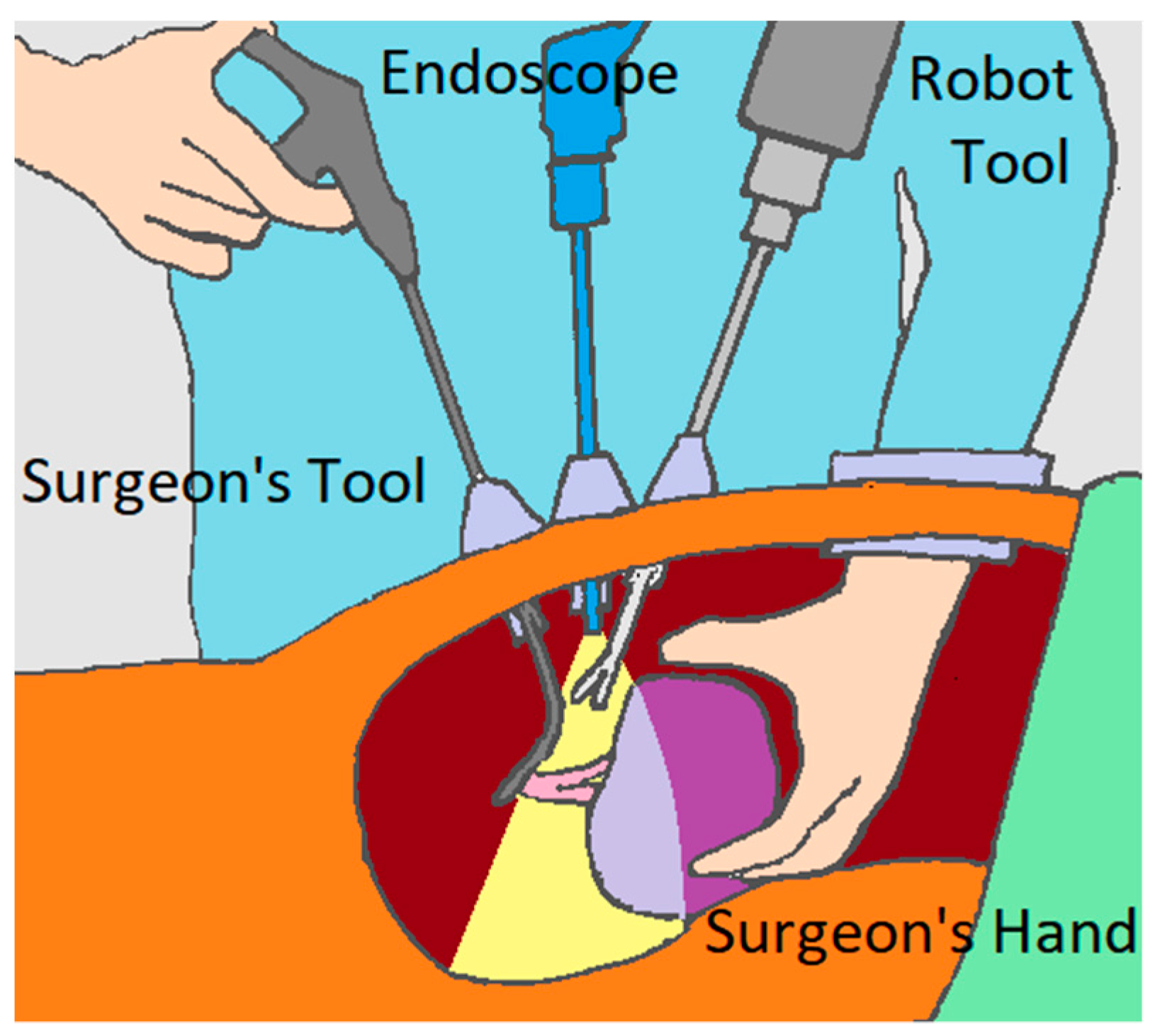
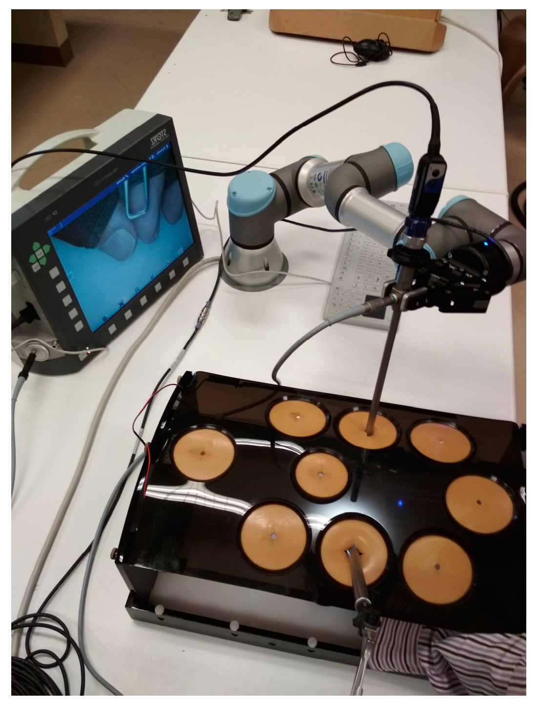
The glove will communicate with a collaborative robot to assist during a HALS. The actions to test the collaborative robot take into account the various robotic actions covered by the literature [
20], among which are the guidance of the laparoscopic camera for the safe movement of the endoscope [
21] or a needle insertion [
22], the prediction of the end point [
23,
24], the knotting and unknotting on suture procedures [
25], or grasping and lifting on tissue retraction [
26]. Ultimately, we selected three actions to be performed by the collaborative robot: center the image from the endoscope, indicate a place to suture, and stretch the thread to suture. These actions are performed in a cholecystectomy, which is the surgical removal of the gallbladder.
Each of the three robot actions mentioned above is associated with a hand movement to be performed by the surgeon. Therefore, the system must be prepared to unambiguously recognize the different movements defined as commands for the robot in order to prevent it from performing undesirable operations. They will be differentiated by the detection algorithm, which is tested with a protocol.
The protocol includes these three movements, which must be detected as robot commands, and are shown in
Table 1 and numbered from 1 to 3. Actions 4 and 5 are introduced to test the developed algorithm. These were selected for their similarity to the movements selected in both the sensor value and motion patterns. As a result, differentiation in advance between the different movements is difficult.
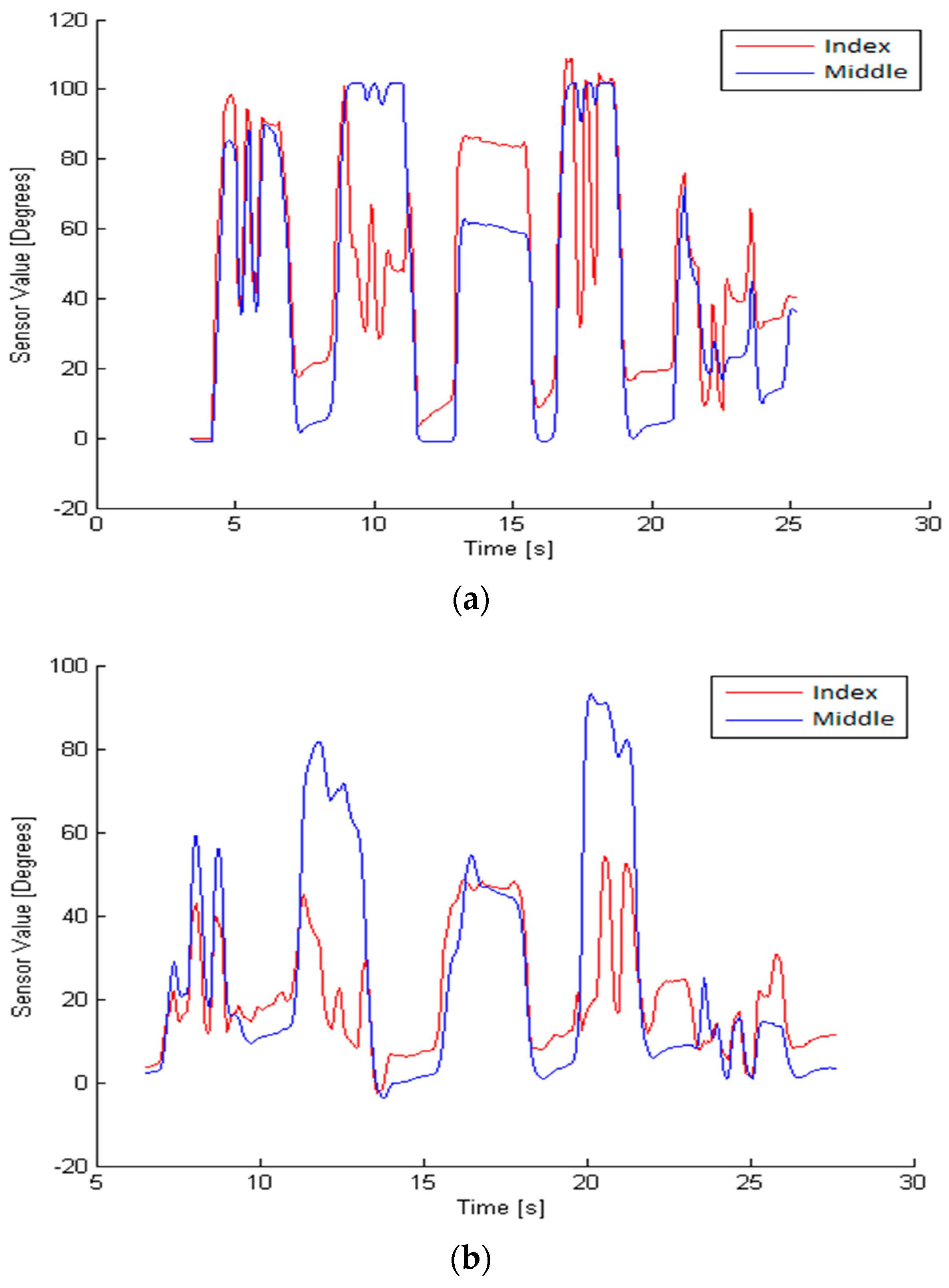
To detect these movements, the developed algorithm analyzes the following parameters: flexion pattern, velocity, execution times, and value provided by the sensor of each finger. To evaluate these parameters, there is a previous phase in which the variables of each movement in each person are examined. This previous stage is required for each person, because the speed and timing of the finger movement is highly variable, as shown in
Figure 4.
Once these variables are defined, as explained in later paragraphs, the detection algorithm can identify each of the three movements.
The motion of the index and middle fingers is sensed by the glove. The acquired data is continuously processed by the developed algorithm in order to detect some of the predefined dynamics patterns. Due to the unique textile substrate to which of all the sensors are attached, cross-talk between sensors may appear. This could be observed as a disturbing signal from a finger when the operator tries to move another finger, as shown in
Figure 5. These movements are filtered in order to avoid a misclassification.
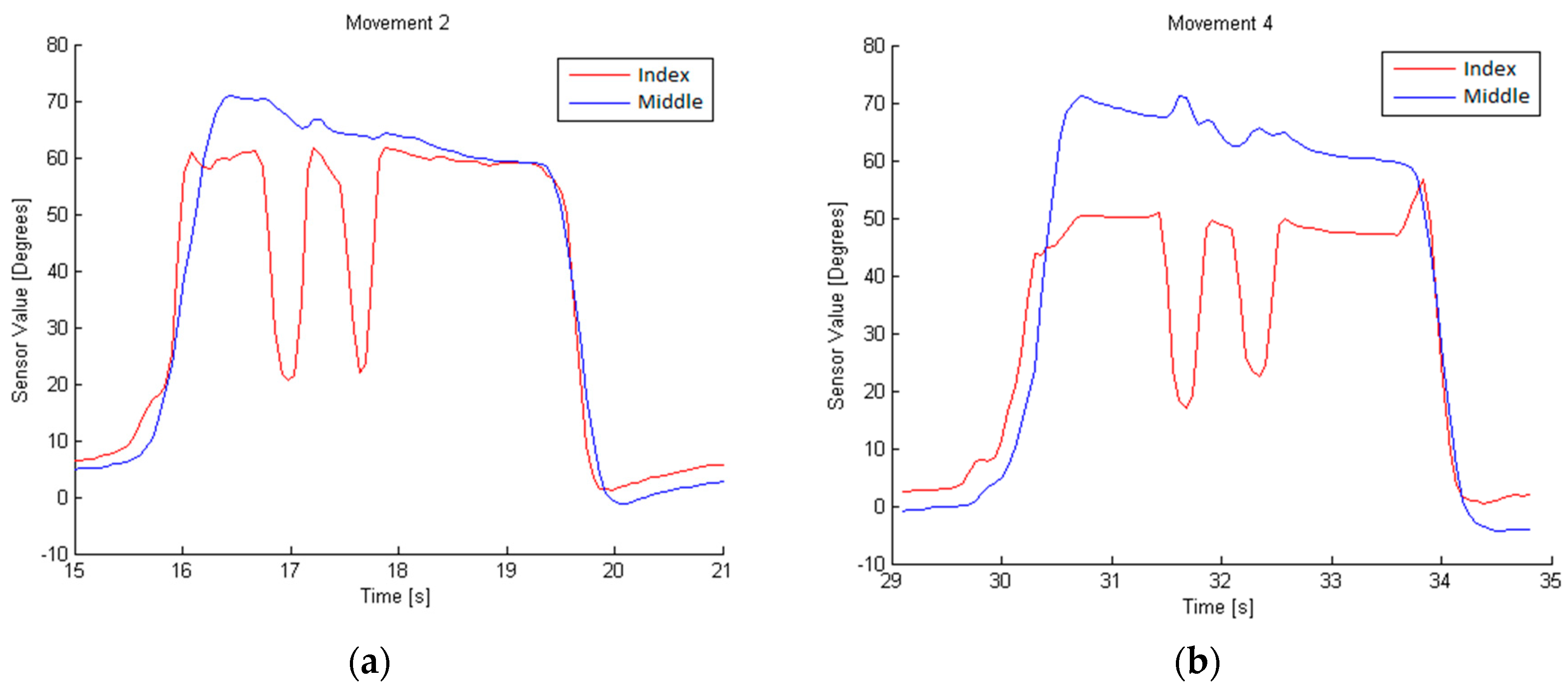
Due to the nature of the sensors used, it is possible to determine the degree of flexion being applied to the sensor on the glove. However, movements 4 and 2 could be confused due to their similarity, as shown in
Figure 6.
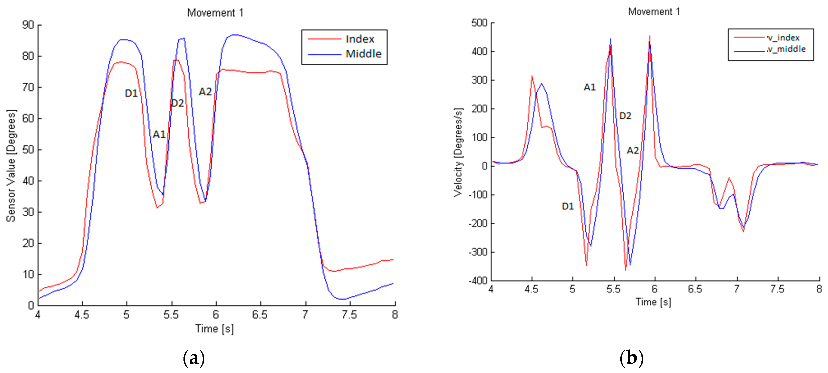
Movement 1 can be identified by analyzing the data from the index and middle fingers. Each rise and fall in the glove sensor values corresponds to the flexion and extension movements of the fingers. This movement consists of a descent (called D1) and ascent (A1), followed by another descent (D2) and ascent (A2), as shown in
Figure 7. This is the flexion pattern considered for movement 1. The D time and A time are, respectively, the times taken during a descent or ascent.
The flexion velocity involved in this dynamic gesture is higher than the cross-talk ones, as shown in
Figure 7b. To establish the typical velocity for this movement, the average and the standard deviation of the velocity along D1 and D2, and A1 and A2, are calculated. This typical velocity, V
1u, is the minimum value obtained from the subtraction of the standard deviation from the average in three tests performed by the same person. The minimum time during descents, t
1Du, (D1 and D2) and ascents, t
1Au, (A1 and A2) is also calculated, and will represent the characteristic ascent and descent execution times of movement 1.
To determine the execution time, t1u, the maximum time in which the whole movement is performed is considered; that is D1, A1, D2, and A2.
The last parameters to be defined are the maximum, xmax, and minimum, xmin, values of the sensor, which set the thresholds to consider if the obtained values are part of movement 1. They are obtained by analyzing three movement samples from the same person.
With these parameters, shown in
Table 2, movement 1 can be defined and differentiated from others, considering the flexion velocity V
e as the instantaneous velocity scanned during the entire movement performed, and the execution time t
e as the time in which the velocity exceeds the velocity threshold.
Using the graphs obtained during the performance of movement 2, as shown in
Figure 8, we can conclude that it is necessary to determine the movements of the index and middle finger in order to obtain a definition. The flexion pattern for this movement is D1, A1, D2, and A2 for the index finger, and no movement for the middle finger. The velocity, time of execution, minimum time during descents (D1 and D2) and ascents (A1 and A2), and the sensor value are defined as described in movement 1.
Movement 3, in
Figure 9, differs from the other two in that the velocity must be 0, so it is a static position maintained for a certain time. To identify it, we examine the values of the index and middle finger sensors, which will be proportional to the flexion carried out by the finger with the sensor.
The algorithm for the detection of defined movements evaluates all of the abovementioned parameters, and detects when one of these movements is executed.
