Article

Wireless Accelerometer for Neonatal MRI Motion Artifact Correction

Academic Radiology, University of Sheffield, Sheffield S10 2JF, UK
*
Author to whom correspondence should be addressed.
Technologies 2017, 5(1), 6; https://doi.org/10.3390/technologies5010006
Submission received: 9 November 2016 / Revised: 10 January 2017 / Accepted: 17 January 2017 / Published: 22 January 2017
(This article belongs to the Special Issue Medical Imaging & Image Processing Ⅱ)

Abstract

:
A wireless accelerometer has been used in conjunction with a dedicated 3T neonatal MRI system installed on a Neonatal Intensive Care Unit to measure in-plane rotation which is a common problem with neonatal MRI. Rotational data has been acquired in real-time from phantoms simultaneously with MR images which shows that the wireless accelerometer can be used in close proximity to the MR system. No artifacts were observed on the MR images from the accelerometer or from the MR system on the accelerometer output. Initial attempts to correct the raw data using the measured rotational angles have been performed, but further work will be required to make a robust correction algorithm.

1. Introduction

Methods used for motion correction in MRI include navigator pulses, optical tracking devices and post-processing software methods as well as some preliminary evaluation of techniques which use wireless data. The non-wireless based methods have some advantages but also suffer from increased acquisition time, limited visual access and extended reconstruction times, respectively [1,2,3,4,5,6,7,8,9,10,11]. This feasibility study measured 3D motion in real time using a wireless accelerometer to provide correction data for single angle, in-plane rotations which are common in neonatal imaging and difficult to correct with MR based navigator techniques. Data were acquired from a moving test object together with the wireless motion measurement information using a prototype dedicated 3T neonatal MRI system located for clinical evaluation on the Neonatal Intensive Care Unit (NICU), Figure 1.
Nodding and side-to-side motions are also important in creating artifacts on neonatal MRI but in this feasibility study we chose to restrict the motion to just one dimension using axial image acquisition only. Different modes of one-dimensional motion are illustrated in Figure 2 [11]. By choosing either sagittal or coronal image planes, head nodding backwards and forwards or side to side could also be corrected using this method.
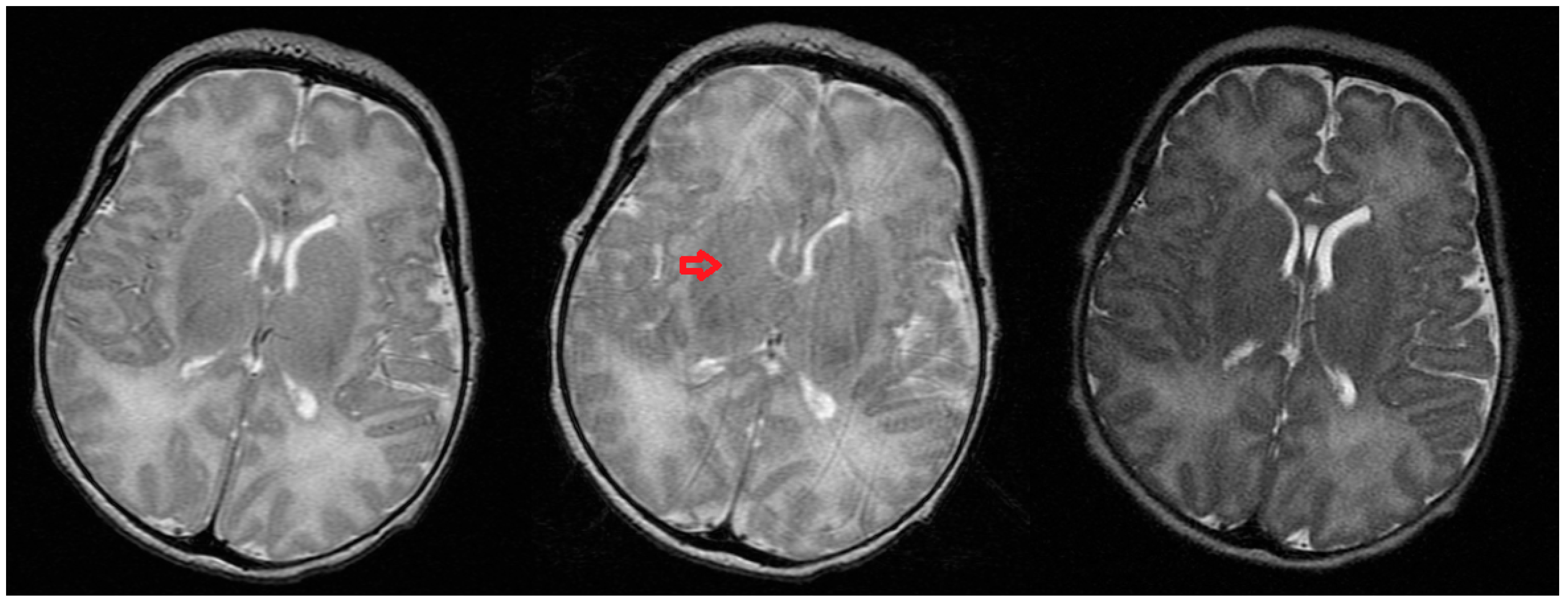
Typical artifacts obtained during neonatal in-plane head rotation, as observed visually during scanning, are shown in Figure 3 [11].
Preliminary testing of a motion correction algorithm which uses wireless data acquired simultaneously with MR images is presented.

2. Experimental Section

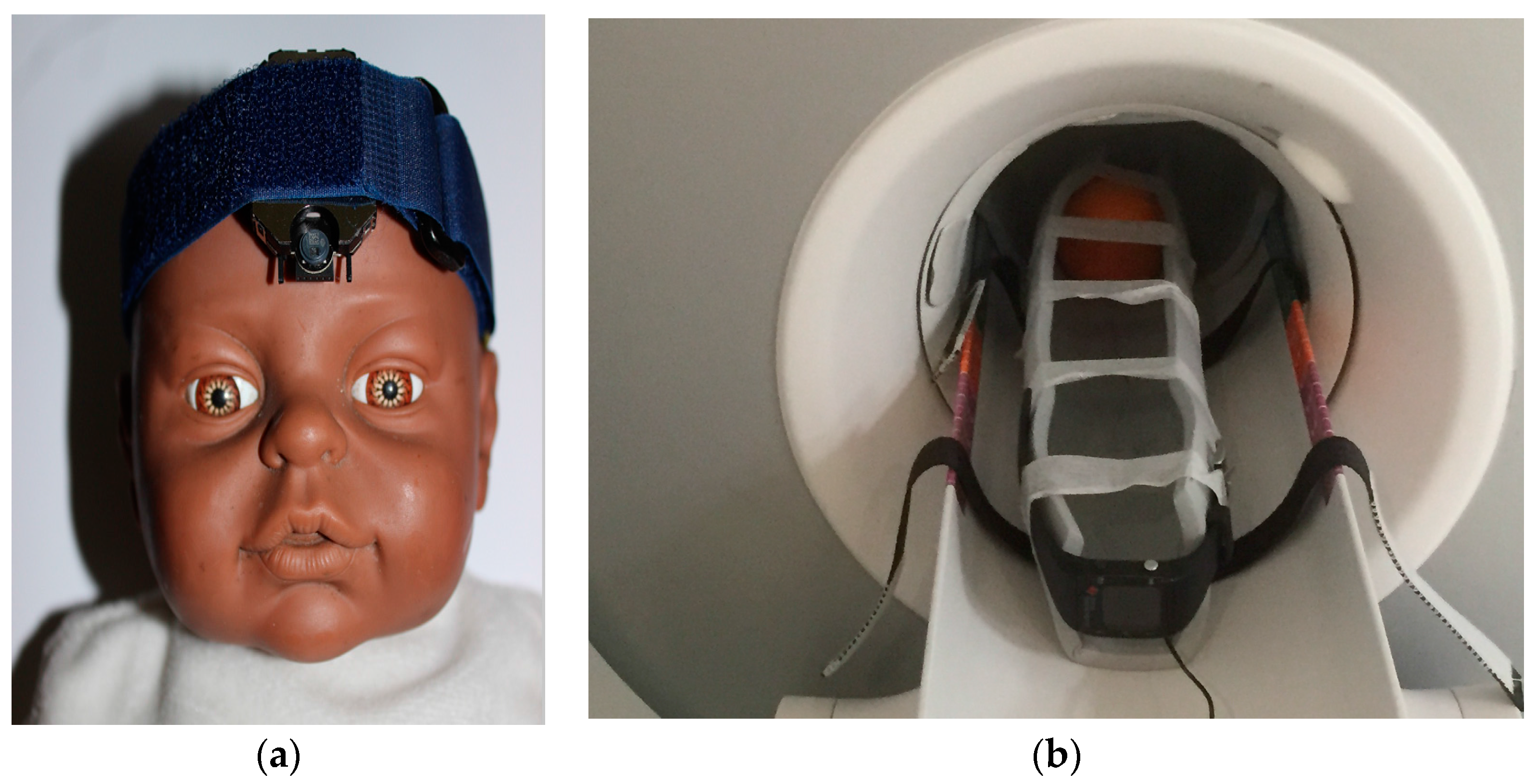
A wireless accelerometer, conveniently housed in a waterproof watch casing operating at 866 MHz (EZ-Chronos Model 430, Texas Instruments, Austin, TX, USA) (Figure 4), was interfaced to software written in LabView (National Instruments, Austin, TX, USA). Acceleration outputs of the device were allocated to three rotation angles—alpha, beta and gamma corresponding to rotation in axial, sagittal and coronal planes respectively. Zero position was set with the watch located horizontally and pointing into the magnet. Rotation of the accelerometer by ±90° around one axis (alpha) was then calibrated and data recorded during scanning.
A USB PC interface to the wireless accelerometer, including a low power RF transceiver (TI CC1111, Texas Instruments, Austin, TX, USA), was housed in the scan computer located outside the screened room to receive the wireless data stream. Angular accuracy and slice offset were previously assessed at 0.17T on a low field dedicated neonatal/extremity MRI system (Niche, Innervision MRI Ltd., Bradley, UK) using a customized quality assurance (QA) phantom [12].
The accelerometer in its current form has some low residual magnetism and so must be kept >100 mm from the entry to the magnet and linked to the object being imaged mechanically. This was achieved by taping the watch to a lightweight, thin foam pad which was also wrapped around and taped to the test object as shown in Figure 4b. The battery is the most magnetic element of the accelerometer assembly and so in this study was located remotely through coaxial wiring. Non-magnetic batteries are relatively difficult to source and expensive so were not used for this evaluation study but are commercially available. Some of the metal support structures for the electronics inside the watch were also made of weakly ferromagnetic material but were not removed to allow switching of the watch functions to be completed (e.g., turning on the wireless signal).
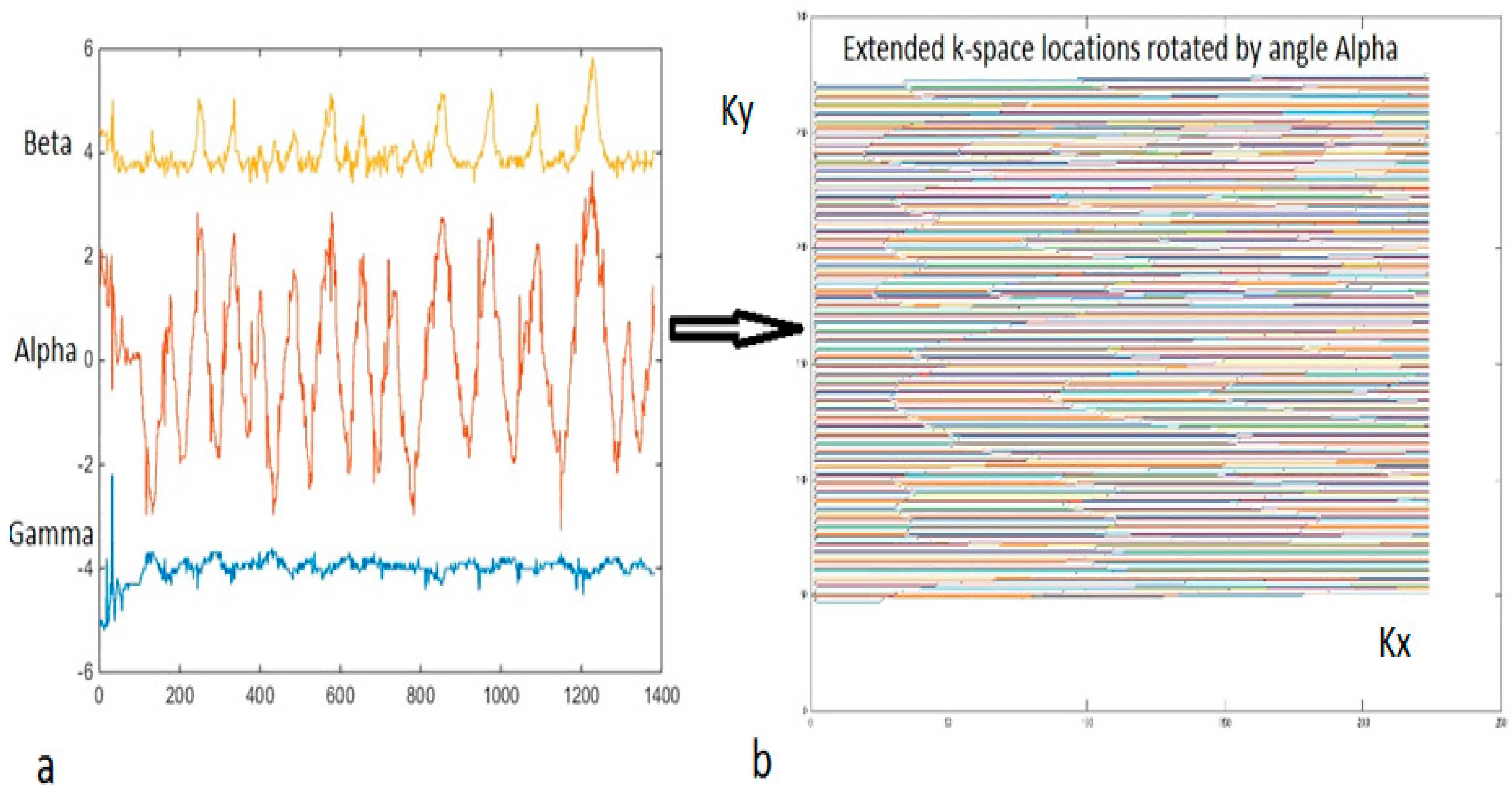
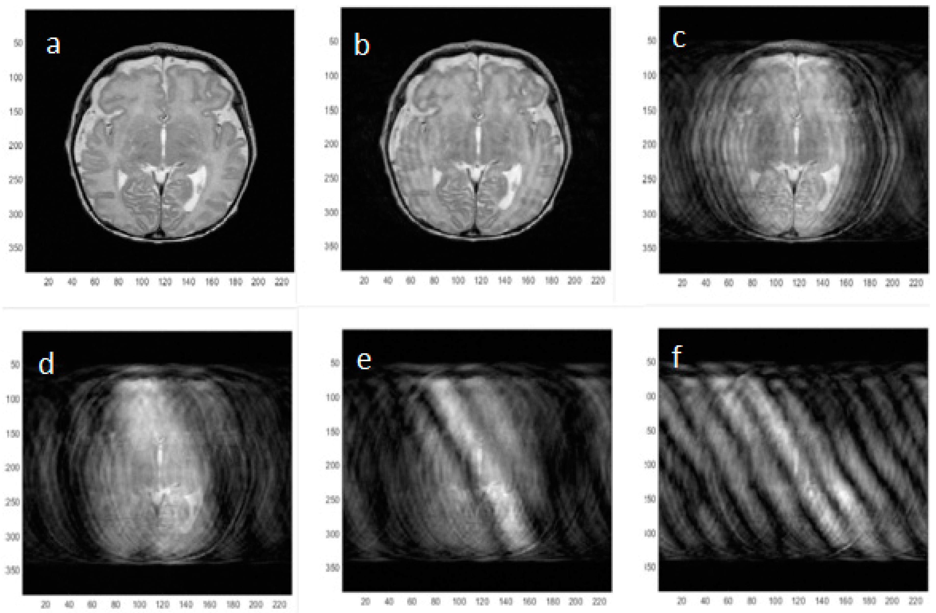
To better understand the effects of rotational motion on neonatal MR images, artifacts were simulated using a measurement of angular in-plane motion acquired using the accelerometer applied to an image k-space data set acquired with no motion artifacts. A measured motion file was downsampled to match the number of phase encoding steps and the k-space locations rotated accordingly (Figure 5). Following image reconstruction of the rotated data sets, the image artifacts created by successively doubling the amount of angular rotation applied were assessed visually.
In addition, MR Images were acquired on the 3T neonatal MRI system with an axial SE image sequence (TR/TE = 300/15 ms, SLT = 3 mm, in-plane resolution = 1 mm, NEX = 1) with and without rotation of the test object through pseudo-sinusoidal angles while simultaneously acquiring motion data. MR signal for each phase step read point was assigned to a new k-space location based on the measured angle, using Matlab. Extension of the data matrix by 100 data points in both dimensions and centering of the actual data matrix was used to allow for rotations of k-space as shown in Figure 5 above.

3. Results and Discussion

The wireless interface operated effectively during image acquisition. The wireless device was not affected by the magnetic or radiofrequency fields during imaging (the device was kept outside the transmit coils) and did not produce interference on the images. This was to be expected given the widely different operating frequencies between the device (868 MHz) and the MR Larmor frequency used (128 MHz). The USB interface was extended partially into the RF screened room waveguide to provide improved reception with the RF screened room door fully closed.
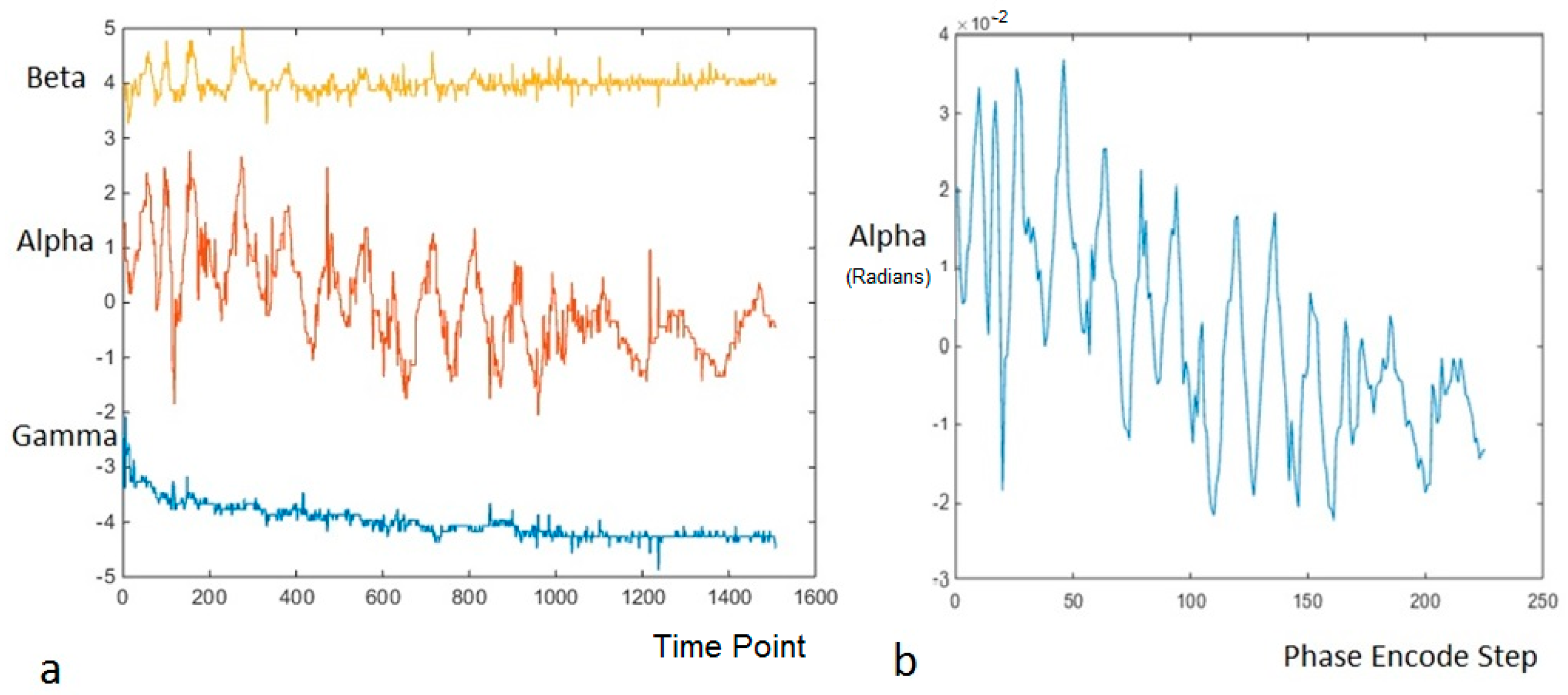
Wireless accelerometer angles were recorded while moving the watch in a pseudo-sinusoidal manner as shown in Figure 5. The measurements were then sub-sampled by averaging together to match the number of the phase encode steps used for the simulation shown in Figure 6.
In Figure 7, Figure 8 and Figure 9 the effects of correcting MR k-space data of the test object acquired on the dedicated 3T Neonatal MRI system with simultaneously acquired wireless accelerometer data are shown for cases of both weak and strong angular motion. Some weak non-planar motion is observed in the beta and gamma channels in Figure 7a, despite best attempts to keep the motion restricted to one-plane. Figure 7b shows the result of down-sampling the alpha channel (axial in-plane rotation) of the wireless accelerometer to match the corresponding phase encode steps in time. The resultant averaging of the signal improves the signal to noise ratio of the angular measurements. The previously measured angular calibration of the accelerometer was used to convert the measurements into radians.
An example of relatively weak axial in-plane rotational motion of the test object (shown static in Figure 8a) is shown in Figure 8b, corresponding to the wireless accelerometer measurements shown in Figure 7b. The peak-to-peak angular variation was ~5 × 10⁻² radians through the MR acquisition, similar to the simulation shown in Figure 6b. No artifacts from the radiofrequency or gradient pulses of the MR system are seen on the accelerometer traces. As the measurement is made totally independently from the MR scanner, there was no MR acquisition time penalty incurred. An attempt to correct the image motion artifact is shown in Figure 8c. Careful inspection of the internal segmental structure of the orange (dark lines) shows some subtle improvement in signal intensity assignment.
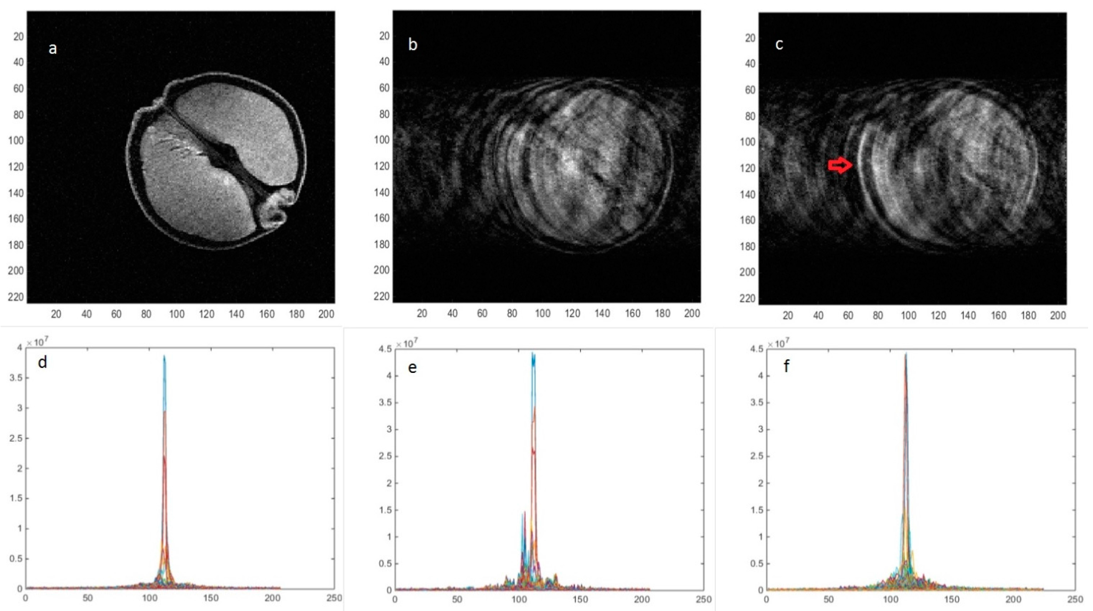
Images acquired with approximately five times more angular motion (2 × 10⁻¹ radians), similar to the simulation shown in Figure 6e, are shown without and with motion in Figure 9a,b respectively and the result of the motion correction algorithm is shown in Figure 9c. The effects of the correction on the original k-space data are shown in Figure 9d–f. It can be seen that several offset k-space lines have been reassigned after the correction, although the overall correction still shows considerable artifact.
The red arrow on Figure 9c illustrates improved left edge definition produced by the correction. The large spikes offset from the center of k-space by motion seen in Figure 9e are removed by the correction algorithm as shown in Figure 9f but serious phase errors still remain in the data set causing residual ghosting.
Rotation angles could be measured in real time using the wireless accelerometer simultaneously with MR image acquisition and used retrospectively to correct these acquired images for in-plane rotations, although further improvements to the motion correction algorithm are required. This method could be applied to 1D motion in sagittal or coronal orientations using data from the beta or gamma channels or for any oblique orientation by combining angular data from all three channels. The geometry and contrast of the moving fruit was improved slightly with angular correction.
The accelerometer provides full real-time 3D motion information so could also be used to simultaneously measure and additionally correct translational and through–plane motion. In Figure 5 and Figure 7, it can be seen that despite the attempt to create just one dimensional motion, there was some residual motion in beta (nodding) and gamma (side to side) angle measurements, which may contribute to the motion correction not being complete. Further development of the reconstruction algorithm to include these angles with a volumetric data set and interpolation of the blank “pie-slice” regions of k-space created by rotation of the data matrix should improve the correction.
Further work is required to reduce the magnetic content of the watch assembly and battery and to reduce the requirement for a mechanical linkage, although the wrapped foam pad provided a method which could in principle be used to mechanically connect a neonatal head and the accelerometer with comfort and safety. Weak residual magnetism of the watch might have been responsible for modulating the B0 field slightly during motion and producing additional artifacts which could not be corrected using the measured motion information. However, although this cannot be completely ruled out, no obvious distortion of the static MR images was seen with or without the watch at the end of the mechanical linkage.
The device could be used for independently triggering a range of prospective gating methods with addition of extra hardware to interact with the MRI gating systems such as ECG or respiratory triggering [13]. Knowing the 3D motion in real time may also allow strategic real-time slice planning to minimize the effects of motion or to ease the motion correction process by acquiring in a plane that reduces the correction burden.

4. Conclusions

A wireless accelerometer system may prove useful for retrospective neonatal MRI motion correction with further development and could also be used for guidance of prospective motion correction and gating techniques. We are planning to extend this novel motion measurement method to correcting motion for neonates on our dedicated 3T neonatal MR system when further engineering improvements in terms of magnetic compatibility and safety testing have been accomplished.

Acknowledgments

We acknowledge the Wellcome Trust and GE Healthcare for providing the dedicated Neonatal MR system.

Author Contributions

M.P. conceived and designed the experiments, M.P., M.H. and N.I. performed the experiments, M.P. and S.R. analysed the data. P.G. and D.J. supervised and performed the clinical scanning of neonates, all authors contributed to writing the paper.

Conflicts of Interest

The authors have no conflict of interest.

References

  1. Hinks, R.S.; Picker International, Inc. Monitored Echo Gating for the Reduction of Motion Artifacts. U.S. Patent 4,761,613, 2 August 1988. [Google Scholar]
  2. Spraggins, T.A. Wireless retrospective gating: Application to cine cardiac imaging. Magn. Reson. Imag. 1990, 8, 675–681. [Google Scholar] [CrossRef]
  3. Crowe, M.; Larson, A.; Zhang, Q.; Carr, J.; White, R.; Li, D.; Simonetti, O. Automated rectilinear self-gated cardiac cine imaging. Magn. Reson. Med. 2004, 52, 782–788. [Google Scholar] [CrossRef] [PubMed]
  4. Larson, A.; White, R.; Laub, G.; McVeigh, E.; Li, D.; Simonetti, O. Self-gated cardiac cine MRI. Magn. Reson. Med. 2004, 51, 93–102. [Google Scholar] [CrossRef] [PubMed]
  5. Thompson, R.B.; Mcveigh, E.R. Flow-gated phase-contrast MRI using radial acquisitions. Magn. Reson. Med. 2004, 52, 598–604. [Google Scholar] [CrossRef] [PubMed]
  6. Holmes, W.; McCabe, C.; Mullin, J.; Condon, B.; Bain, M. Noninvasive selfgated magnetic resonance cardiac imaging of developing chick embryos in ovo. Circulation 2008, 117, e346–e347. [Google Scholar] [CrossRef] [PubMed]
  7. Nieman, B.J.; Szulc, K.U.; Turnbull, D.H. Three-dimensional, in vivo MRI with self-gating and image coregistration in the mouse. Magn. Reson. Med. 2009, 61, 1148–1157. [Google Scholar] [CrossRef] [PubMed]
  8. Xiang, Q.S.; Henkelman, R.M. K-space description for MR imaging of dynamic objects. Magn. Reson. Med. 1993, 29, 422–428. [Google Scholar] [CrossRef] [PubMed]
  9. Callaghan, M.F.; Josephs, O.; Herbst, M.; Zaitsev, M.; Todd, N.; Weiskopf, N. An evaluation of prospective motion correction (PMC) for high resolution quantitative MRI. Front. Neurosci. 2015, 9. [Google Scholar] [CrossRef] [PubMed]
  10. Atkinson, D.; Hill, D.L.G.; Stoyle, P.N.R.; Summers, P.E.; Keevil, S.F. Automatic Correction of Motion Artefacts in Magnetic Resonance Images Using an Entropy Focus Criterion. IEEE Trans. Med. Imag. 1997, 16, 903–910. [Google Scholar] [CrossRef] [PubMed]
  11. Malamateniou, C.; Malika, S.J.; Counsell, S.J.; Allsop, J.M.; McGuinness, A.K.; Hayata, T.; Broadhouse, K.; Nunes, R.G.; Ederiesc, A.M.; Hajnal, J.V.; et al. Motion-Compensation Techniques in Neonatal and Fetal MR Imaging. AJNR 2013, 34, 1124–1136. [Google Scholar] [CrossRef] [PubMed]
  12. Paley, M.N.; Ledger, A.; Leach, M.O.; Cummings, C.; Hughes, R.; Akgun, A. Wireless Accelerometer for MRI-Guided Interventional Procedures. Technologies 2013, 1, 44–53. [Google Scholar] [CrossRef]
  13. Paley, M.N.; Morris, J.E.; Jarvis, D.; Griffiths, P.D. Fetal electrocardiogram (fECG) gated MRI. Sensors 2013, 13, 11271–11279. [Google Scholar] [CrossRef] [PubMed]
Figure 1. The prototype Firefly dedicated 3T neonatal MRI system (GE Healthcare, Milwaukee, WI, USA) installed on the Neonatal Intensive Care Unit (NICU) for clinical evaluation.
Technologies 05 00006 g001
Figure 2. Different modes of neonatal head motion which could be corrected using one dimensional angular information from the wireless accelerometer. Extension to oblique orientations and to full 3D correction should also be possible but requires further work on the reconstruction algorithm.
Technologies 05 00006 g002
Figure 3. The image on the left is a Fast Spin Echo (FSE) image acquired over two minutes showing no motion artefact, the image in the middle is the same sequence showing artifact due to neonatal in-plane rotational head movement, as noted visually, which is commonly seen when imaging neonates [11]. The image on the right is a single shot fast spin echo showing no motion artefact but with inferior signal to noise ratio and resolution.
Technologies 05 00006 g003
Figure 4. (a) Possible mounting location of the accelerometer shown without the watch housing (EZ Chronos model 430, Texas Instruments, Austin, TX, USA) on a neonate, if the weakly ferromagnetic components and the battery were replaced. We are not currently authorized to make these measurements on neonates ethically, so this study is aimed at investigating the practicality and safety of such measurements in preparation for later in vivo studies; (b) Shows the foam pad mechanical linkage used to keep the watch just outside the fringe field of the magnet, for imaging the test object (orange) while simultaneously measuring the motion introduced by rotating the pad manually. For the experiments performed here, the watch was located horizontally. A non-magnetic coaxial cable leading from the watch internal battery terminals to the battery (C2032) located in a switched holder at the end of the patient bed can be seen at the bottom of the picture.
Technologies 05 00006 g004
Figure 5. (a) Raw wireless accelerometer 3-channel output measuring three rotation angles alpha, beta and gamma is shown. Traces for beta and gamma angles are offset by ±4 (a.u.) for convenience; (b) Shows the k-space locations used for simulation of motion artifacts based on the measured angle alpha. The angles were successively doubled for each simulation as listed in the text.
Technologies 05 00006 g005
Figure 6. Simulated neonatal axial MR images incorporating increasing amounts of in-plane pseudo-sinusoidal angular motion (alpha) as shown in Figure 5. The original image with no motion artifact is shown in (a) and then the peak-to-peak angular motion applied to the k-space locations is doubled in successive images (b) 2 × 10⁻²; (c) 4 × 10⁻²; (d) 8 × 10⁻²; (e) 1.6 × 10⁻¹; (f) 3.2 × 10⁻¹ radians to simulate neonatal head motion. A standard rotation matrix was used to multiply the k-space locations by the relevant measured angle. In principle, reversal of the motion effects by counter-rotating the k-space data according to the measured rotation angles should be possible.
Technologies 05 00006 g006
Figure 7. (a) Three channel rotation angles (arbitrary units) measured using the wireless accelerometer during imaging of the pseudo-sinusoidally rotated test object corresponding to Figure 8b below. The time resolution of the measurements was 45 ms and the data for in-plane rotation (alpha channel) was subsequently down-sampled, calibrated in radians and registered to match the acquired phase encode steps as shown in (b).
Technologies 05 00006 g007
Figure 8. MR images of an orange acquired on the 3T neonatal MRI system with no in-plane angular motion (a) and pseudo-sinusoidal in-plane rotational motion about the iso-centre; (b) corresponding to the measurements shown above in Figure 7; (c) an attempt to remove the motion using the measured rotation angles shows some subtle improvement of image quality.
Technologies 05 00006 g008
Figure 9. MR images with no in-plane angular motion (a); and pseudo-sinusoidal motion (b); In (c), an attempt to remove the motion using the measured angles shows some improvement of the k-space data as can be seen by comparing (df) where the individual k-space lines are plotted together.
Technologies 05 00006 g009