Article

Using Solar Sails to Rendezvous with Asteroid 2024 YR4

by
Alessandro A. Quarta
Department of Civil and Industrial Engineering, University of Pisa, I-56122 Pisa, Italy
Technologies 2025, 13(8), 373; https://doi.org/10.3390/technologies13080373
Submission received: 22 July 2025 / Revised: 8 August 2025 / Accepted: 18 August 2025 / Published: 20 August 2025

Abstract

This paper aims to present a set of possible transfer trajectories for a rendezvous mission with asteroid 2024 YR4, using a spacecraft propelled by a photonic solar sail. Asteroid 2024 YR4 was discovered in late December 2024 and was briefly classified as Torino Scale 3 for three weeks in early 2025, before being downgraded to zero at the end of February. In this study, rapid Earth-to-asteroid transfers are analyzed by solving a typical optimal control problem, in which the thrust vector generated by the solar sail is modeled using the optical force approach. Numerical simulations are carried out assuming a low-to-medium performance solar sail, considering both a simplified orbit-to-orbit transfer and a more accurate scenario that incorporates the actual ephemerides of the celestial bodies. The numerical results indicate that a medium-performance solar sail can reach asteroid 2024 YR4, achieving the global minimum flight time and arriving before its perihelion passage in late December 2032.

1. Introduction

The continuous monitoring [1] and, potentially, the rapid and close observation [2] or long-term exploration [3,4] of Potentially Hazardous Asteroids (PHAs) represent a fundamental step toward protecting our planet from threats associated with the possible impact of these minor bodies of the Solar System [5,6]. The recent discovery [7] of asteroid 2024 YR4, which occurred in late December 2024, has once again sparked public interest in the risks posed by such celestial objects and has further intensified the scientific community’s focus on the close-up study and remote monitoring of PHAs. In early 2025, based on the observations and data available at that time, asteroid 2024 YR4 was assigned level 3 according to the well-known Torino Impact Hazard Scale [8], due to a small (but not negligible) risk of impact with Earth projected for late December 2032 [9]. However, risk assessments are continuously updated as observational data improve and, as demonstrated in the case of asteroid 99942 Apophis [10], can be reduced to zero following a temporary and modest increase. This was also the case for asteroid 2024 YR4, whose impact risk with Earth dropped essentially to zero around mid-February 2025, thanks in part to data provided by NASA’s James Webb Space Telescope [11,12]. Currently, a non-negligible probability remains that the asteroid could impact the Moon’s surface in late 2032.
In this context, the asteroid’s next perihelion passage, expected around the end of 2028, will offer an opportunity for more in-depth remote sensing of its characteristics and a refined analysis of its heliocentric orbit, supported by measurements from both ground-based and space-based telescopes [13]. In any case, asteroid 2024 YR4 stands as a clear example of how the discovery of a new PHA may leave a relatively short time window (i.e., about eight years) to implement all necessary mitigation measures or to plan a scientific mission for close-up investigation of the small celestial body.
Indeed, the upcoming (and potentially even the subsequent) perihelion passage of asteroid 2024 YR4 presents an intriguing opportunity to perform a flyby or even achieve a rendezvous with the object using a robotic probe. Such a close encounter could enable valuable in-situ observations of its external structure and physical composition. Furthermore, as occurred recently with the more well-known asteroid 99942 Apophis [14,15], the case of asteroid 2024 YR4 could serve as a test mission scenario for evaluating the capabilities of both conventional propulsion systems [16] and more advanced and innovative spacecraft thruster concepts [17,18,19]. In this context, the present paper investigates possible rapid transfer trajectories to asteroid 2024 YR4 for an interplanetary spacecraft equipped with a photonic solar sail (sailcraft) [20,21], one of the few propellantless propulsion systems successfully demonstrated in space by pioneering missions such as JAXA’s IKAROS [22,23] and, more recently, by NASA’s ACS3 [24,25].
As is well known, a photonic solar sail utilizes solar radiation pressure to generate net thrust through a large, highly reflective surface coated with a metallic film [26]. In this context, the propulsive performance of a sailcraft—specifically, the maximum magnitude of its acceleration vector at a reference solar distance of one astronomical unit—is strongly influenced by the level of technology employed to manufacture (and subsequently deploy using an appropriate mechanism) a large reflective membrane in space [27]. The transfer performance of the sailcraft was simulated by considering both a low-performance solar sail, consistent with the technology used in the design of NASA’s (unfortunately canceled) Solar Cruiser interplanetary mission [28], and a medium-performance solar sail, which provides an estimate of the potential flight time achievable with (hopefully) near-future technology.
In this work, the sailcraft thrust vector is modeled using the optical force approach [29], which accounts for the thermo-optical properties of the reflective film. The minimum transfer time is evaluated by solving an optimal control problem similar to the one discussed in detail in ref. [30]. It is important to note that this paper does not introduce a new force model for the photonic solar sail, nor does it propose a novel procedure—neither numerical nor analytical—for determining the optimal transfer trajectory of the sailcraft. Rather, the aim of this study is to present the results of a series of optimized trajectory simulations, offering the reader a useful insight into the propulsive performance required to reach asteroid 2024 YR4 within a specified time window. This emphasis is intentional, as the author believes it is valuable to make available optimal (numerical) results concerning potential new application scenarios for a given propulsion system—in this case, a photonic solar sail. These results may subsequently serve as a reference for further refinement of the mathematical model used to describe the solar sail’s thrust vector, or for the inclusion of perturbative effects in the description of the spacecraft’s heliocentric dynamics.
The resulting transfer trajectories are deterministic, meaning that the sailcraft’s heliocentric orbits do not account for any uncertainties in the modeling of the solar sail-induced thrust vector [31]. Additionally, orbital perturbations are neglected in this study, so that the sailcraft’s heliocentric dynamics are influenced solely by the gravitational attraction of the Sun and the thrust generated by the solar sail. Although this approach may appear simplistic, it is precisely the methodology adopted in preliminary mission analyses, which aim to assess the potential performance of a given propulsion system within a specified interplanetary transfer scenario. In this regard, the recent work by Johnson et al. [32,33] serves as an illustrative example of the application of a simple (yet effective) thrust model—namely, the optical force model—in the preliminary design of a new mission concept involving continuous solar observation via a sailcraft positioned near the sub- L 1 point. Indeed, this type of approach enables the exploration of a wide range of possible heliocentric trajectories for the sailcraft with relatively low computational effort. The term “relatively low” is emphasized here, as the technique employed in this paper to determine the optimal sailcraft trajectory—and thus the minimum transfer time—is based on an indirect method that requires, for each scenario, a complex interaction between the designer and the numerical automatic routines. In particular, the choice of a method based on the classical calculus of variations is closely linked to the availability of well-validated routines for optimizing heliocentric transfer trajectories [30], such as those investigated in this work. The consistency of the results obtained using these routines with the outputs of alternative optimization methods—based on a direct approach to flight time minimization—has already been examined in missions targeting 99942 Apophis [17].
A subsequent analysis of this problem could include an investigation of the effects of orbital perturbations on the actual heliocentric trajectory of the sailcraft. Such effects, considering the long flight durations typically associated with the low-thrust levels provided by current-generation solar sails, would require a modification of the (optimal) guidance law to ensure rendezvous with the target asteroid. In this subsequent refinement phase, a more sophisticated thrust model—one that, for example, accounts for the billowing of the sail membrane [34] and the uncertainties [35] associated with the optical characteristics of the reflective film—can be taken into account. In this regard, a possible approach is discussed in the recent ref. [36].
The results of the transfer simulations are presented in Section 2, which also includes a brief description of the model used to represent the acceleration vector induced by the photonic solar sail; see Section 2.1. Specifically, the mission scenario analyzed in the following section is consistent with an Earth-to-asteroid 2024 YR4 interplanetary transfer, in which the sailcraft departs from Earth’s sphere of influence with zero hyperbolic excess velocity and performs a rendezvous with the target small body, following the classical patched-conic approximation of a typical interplanetary transfer [37]. Within this simplified framework, the optimal sailcraft transfer is examined in two sequential phases. The first phase, commonly referred to as orbit-to-orbit transfer, involves optimizing the sailcraft’s heliocentric trajectory without accounting for ephemerides constraints related to the angular positions of the two celestial bodies (i.e., Earth at departure and the target asteroid at arrival) along their Keplerian orbits.
This first phase of the study, referred to throughout the paper as the ephemeris-free transfer (EFT), aims to compute the minimum flight time required to transfer a sailcraft with assigned characteristics between two heliocentric orbits. Viewed from another perspective, the results of this phase enable a rapid estimation of the minimum performance level required for the solar sail—specifically, the minimum value of the reference propulsive acceleration necessary to achieve a rendezvous with asteroid 2024 YR4 within a given flight time. For this reason, the results of the EFT analysis, presented in Section 2.2, constitute a valuable and essential reference dataset for the second phase of the study, which will be referred to as the ephemeris-constrained transfer (ECT).
In this second phase of the study, presented in Section 2.3, the interplanetary transfer of the sailcraft is analyzed by accounting for the actual angular positions of Earth and asteroid 2024 YR4, obtained using JPL’s well-known Horizons system [38]. Specifically, the numerical simulations explore several combinations of the sailcraft’s reference propulsive accelerations and potential launch dates. Naturally, the numerical results of this phase are consistent with those obtained in the EFT analysis, since the sailcraft’s flight time in an ECT is always greater than or, at best, equal to that computed in the EFT. Indeed, the EFT results allow the designer to quickly assess how closely a selected launch window approximates the ideal one, in which the orbital transfer can be achieved within the global minimum flight time.
Accordingly, the novel contributions of this paper consist of the presentation of a set of new numerical results obtained through well-validated techniques. These contributions are essentially twofold:
  • the numerical investigation of optimal performance, in terms of global minimum flight time, for orbit-to-orbit heliocentric transfers as a function of the sailcraft’s propulsive characteristics, namely its reference acceleration value;
  • the analysis of potential rapid rendezvous trajectories constrained by actual planetary ephemerides, in which the launch date spans a time interval of approximately 10 years and the sailcraft’s propulsive characteristics are consistent with those considered in the previous point.
This type of numerical study required the simulation and optimization of a large number of potential transfer trajectories—approximately 8000 in this case.
Finally, Section 2.4 illustrates a mission scenario in which a specific launch date enables a medium-performance sailcraft to rendezvous with asteroid 2024 YR4, achieving both the global minimum flight time (as determined by the EFT study) and an arrival date in mid-May 2029—well before the perihelion passage in late December 2032. This noteworthy result is also emphasized in Section 3, which concludes the paper.

2. Numerical Results for Sailcraft Transfer Scenarios

This section aims to present the results of numerical simulations concerning both the EFT (see Section 2.2) and the ECT (see Section 2.3). Additionally, the first part of the section summarizes the mathematical model used to describe the sailcraft’s thrust vector and briefly discusses the method adopted to compute the interplanetary transfer trajectory. In this regard, Figure 1 presents a flowchart illustrating the strategy adopted to investigate the optimal transfer performance in this specific mission scenario.
In particular, the approach used here to determine the sailcraft’s optimal trajectories coincides with that recently employed by the author [30] in the study of transfer options to comet 29P/Schwassmann–Wachmann 1 [39]. Therefore, ref. [30] provides detailed information about the complete mathematical model and the optimal guidance law that enables the sailcraft to transfer between Earth’s Keplerian orbit and that of asteroid 2024 YR4.
In this regard, and according to JPL’s Horizons system, the classical orbital elements of the two Keplerian orbits as of 1 January 2025 are summarized in Table 1. Specifically, in that table, the term a denotes the semimajor axis of the orbit, e the eccentricity, i the inclination, ω the argument of perihelion, Ω the right ascension of the ascending node, and M the mean anomaly of the celestial body. The value of M at a generic time instant is then obtained by solving the classical Kepler problem, as described in ref. [37].

2.1. Thrust Vector Modeling and Trajectory Computation

The propulsive acceleration vector a induced by the photonic solar sail is modeled using Georgevic’s formulation [40], also referred to in McInnes’s textbook [29] as the “optical force model”. More precisely, this elegant and widely adopted mathematical model assumes a nominal (uniform and flat) membrane and considers the time-invariant optical properties of the reflective film to derive a compact analytical expression for the vector a .
In this context, and based on the optical characteristics of the square solar sail studied by JPL in the late 1970s—summarized in Table 2.1 of ref. [29]—the expression for the propulsive acceleration vector is given by:
a = a c 1 AU r 2 r ^ · n ^ 0.0951 r ^ + 0.9109 r ^ · n ^ 0.0060 n ^ ,
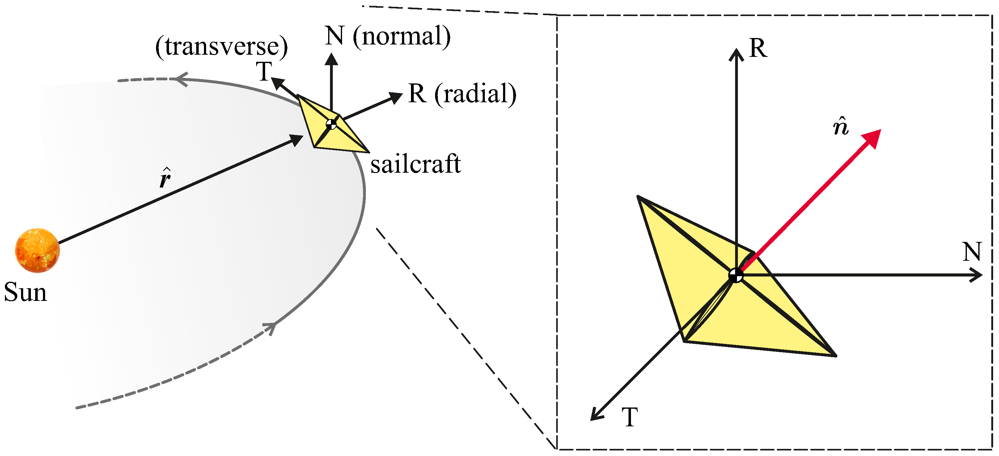
where r is the sailcraft’s solar distance, r ^ is the Sun–sailcraft unit vector, n ^ is the sail membrane’s normal unit vector (oriented opposite to the Sun), and a c is the classical sail performance parameter, commonly referred to as the characteristic acceleration. Specifically, a c represents the maximum magnitude of a when r = 1 AU , while n ^ can be interpreted as a control term, since its components in the radial-transverse-normal (RTN) orbital reference frame define the orientation of the sail membrane’s plane; see the sketch in Figure 2.
Note that, as is well known, the scalar control terms of a (flat) photonic solar sail are actually two, since by definition n ^ = 1 . In fact, the orientation of the normal unit vector can be defined through two suitable angles [41]. However, in this work, we prefer to retain the unit vector n ^ as a vectorial control term, so that the optimal guidance law will be presented, in the following subsections, as a time-dependent variation of the three components of n ^ in the RTN frame.
A change in the membrane material results in a modification of the numerical coefficients appearing in the previous equation. In this context, for example, an update of the optical force model’s coefficients was completed in 2015 using new optical tests on modern materials, as illustrated in the insightful paper by Heaton and Artusio-Glimpse [42]. Nevertheless, the values adopted in this work remain widely used and are consistent with the mathematical model recently employed by other authors [32,33] to investigate sailcraft performance during the preliminary mission design phase.
For a given value of the characteristic acceleration a c , the guidance law and the corresponding sailcraft interplanetary trajectory are computed using the same method detailed in ref. [30], namely by solving a suitable optimal control problem through the classical calculus of variations [43]. Specifically, the numerical integration of the sailcraft’s equations of motion is performed using an Adams–Bashforth–Moulton PECE solver [44] with a tolerance of 10 10 , while the solution of the associated boundary value problem is obtained with a tolerance of 10 7 using a single shooting method [45]. Appendix A summarizes the mathematical model used to describe the sailcraft’s heliocentric trajectory, along with the main equations of the optimization process. Indeed, as emphasized in the introductory section, this work does not introduce novel elements to the literature, as its primary objective is to present the results obtained from trajectory simulations, which are described in the following two subsections.

2.2. Optimized Trajectories in the EFT Scenario

The first part of the study concerning the Earth–asteroid 2024 YR4 sailcraft transfer involves investigating flight performance within an EFT. In this context, the minimum flight time required to complete the orbit-to-orbit transfer is determined by solving an optimal control problem similar to the one presented in ref. [30]. This is done to select the optimal values of both the initial true anomaly ν 0 along Earth’s orbit at the departure point and the final true anomaly ν f along the asteroid’s orbit at the arrival point. The values of ν 0 and ν f are obtained independently of whether these true anomaly values correspond to the actual positions of celestial bodies (ephemeris-free assumption).
This enables the determination, for a given value of the characteristic acceleration a c (i.e., a single design parameter), of the minimum flight time Δ t achievable using that specific sailcraft performance metric. Specifically, numerical simulations were conducted by varying the characteristic acceleration parametrically within the interval a c [ 0.15 , 1 ] mm / s 2 . The lower bound of this range is consistent with the characteristic acceleration of NASA’s recently canceled Solar Cruiser demonstration mission [28], which was designed to enable continuous solar observations using a sailcraft with a c 0.12 mm / s 2 . The central value of the interval, on the other hand, aligns with the performance anticipated in the Solar Polar mission proposal [46], aimed at reaching a high-inclination heliocentric orbit without resorting to planetary gravity assist maneuvers, using a sailcraft with a c 0.4 mm / s 2 . Finally, the upper bound of the interval, a c = 1 mm / s 2 , represents a canonical value of the characteristic acceleration, typically adopted to obtain a first-order estimate of the performance index (usually the flight time) in a given mission scenario.
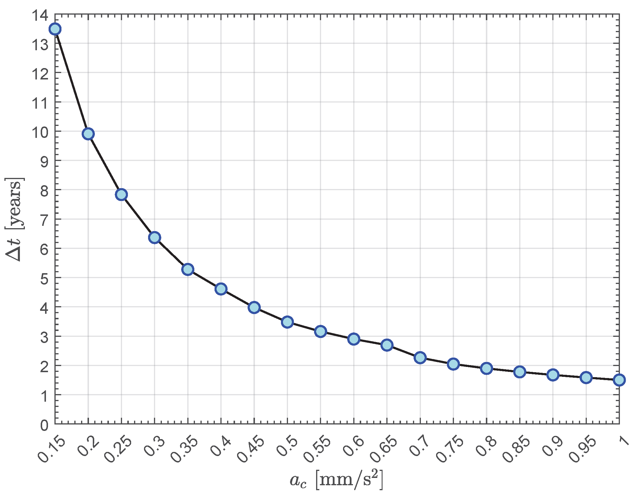
The numerical results of the EFT study are reported in Table 2. Specifically, this table summarizes, as a function of the characteristic acceleration within the interval a c [ 0.15 , 1 ] mm / s 2 , the minimum flight time ( Δ t ), the number of complete revolutions around the Sun (N), the initial true anomaly ( ν 0 ) along Earth’s orbit, and the final true anomaly ( ν f ) along the asteroid’s orbit. Furthermore, Figure 3 shows the graph of the function Δ t = Δ t ( a c ) , obtained numerically from the EFT study. This graph allows the reader to easily assess the minimum number of flight years required to complete the transfer to asteroid 2024 YR4.
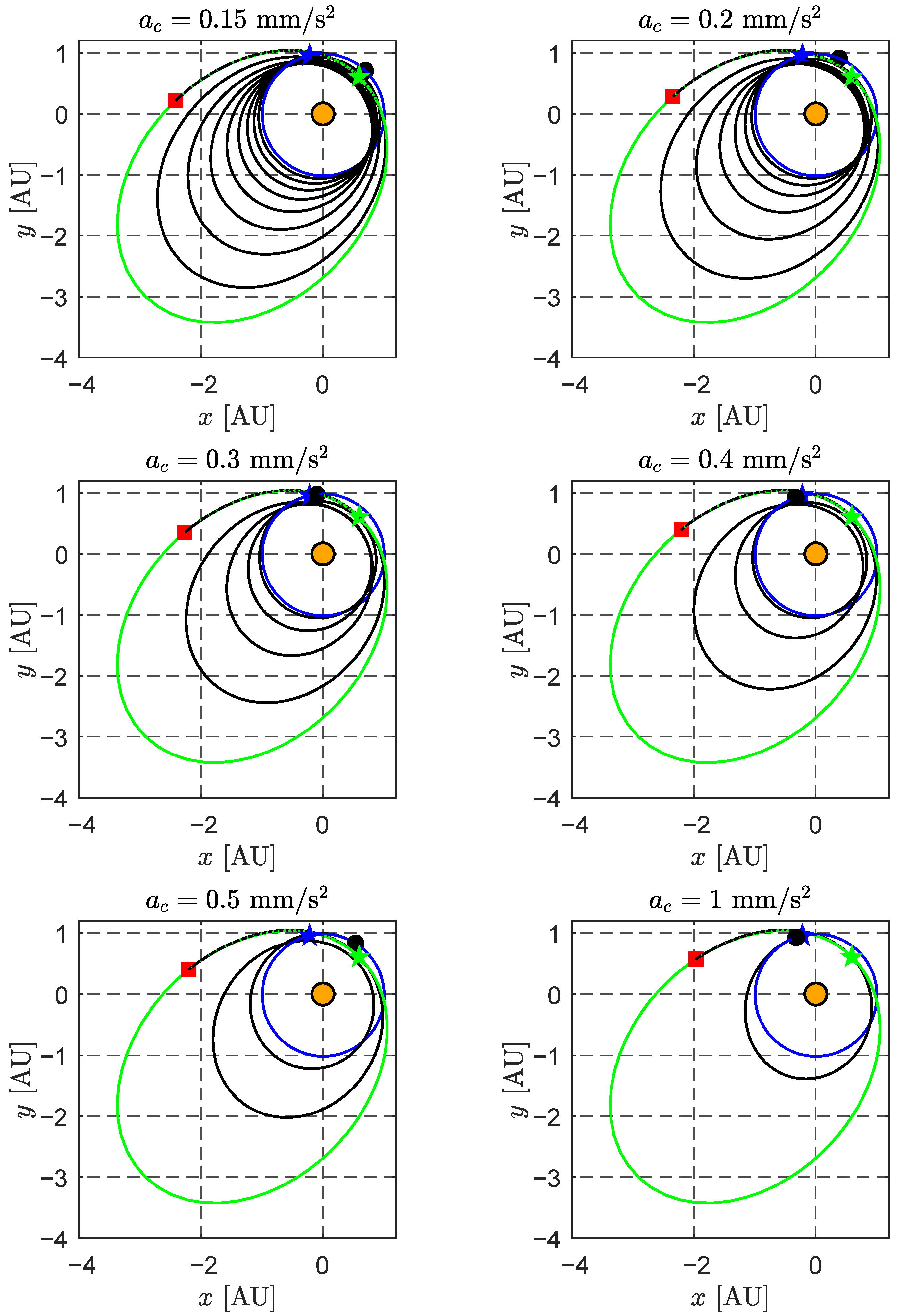
In particular, the value of N serves as an indicator of the complexity of the transfer trajectory. As shown in the table, the number of revolutions around the Sun increases progressively as the characteristic acceleration decreases, a trend clearly illustrated in Figure 4, which displays the sailcraft transfer trajectories for a range of a c values. For example, when a c 0.65 mm / s 2 , the sailcraft completes the transfer with a single revolution. Conversely, when the characteristic acceleration reflects current technological capabilities (i.e., a c = 0.15 mm / s 2 ), the transfer involves N = 8 revolutions and a flight time of approximately 13.5 years .
The curve in Figure 3 clearly shows that a realistic sailcraft-based rendezvous mission with a flight time of less than 4 years —approximately the orbital period of the target asteroid—can be achieved only if the characteristic acceleration exceeds 0.45 mm / s 2 . Conversely, to ensure a flight time of less than 8 years —corresponding to the interval between the asteroid’s discovery and its potentially hazardous [Earth + Moon] flyby—the value of a c must be greater than 0.25 mm / s 2 . This threshold is roughly twice that of the Solar Cruiser proposed mission [28], which is representative of current technological capabilities.
Finally, the slope of the curve in Figure 3 indicates that once a c = 0.7 mm / s 2 is exceeded, further increases in characteristic acceleration yield only marginal reductions in flight time, in absolute terms.
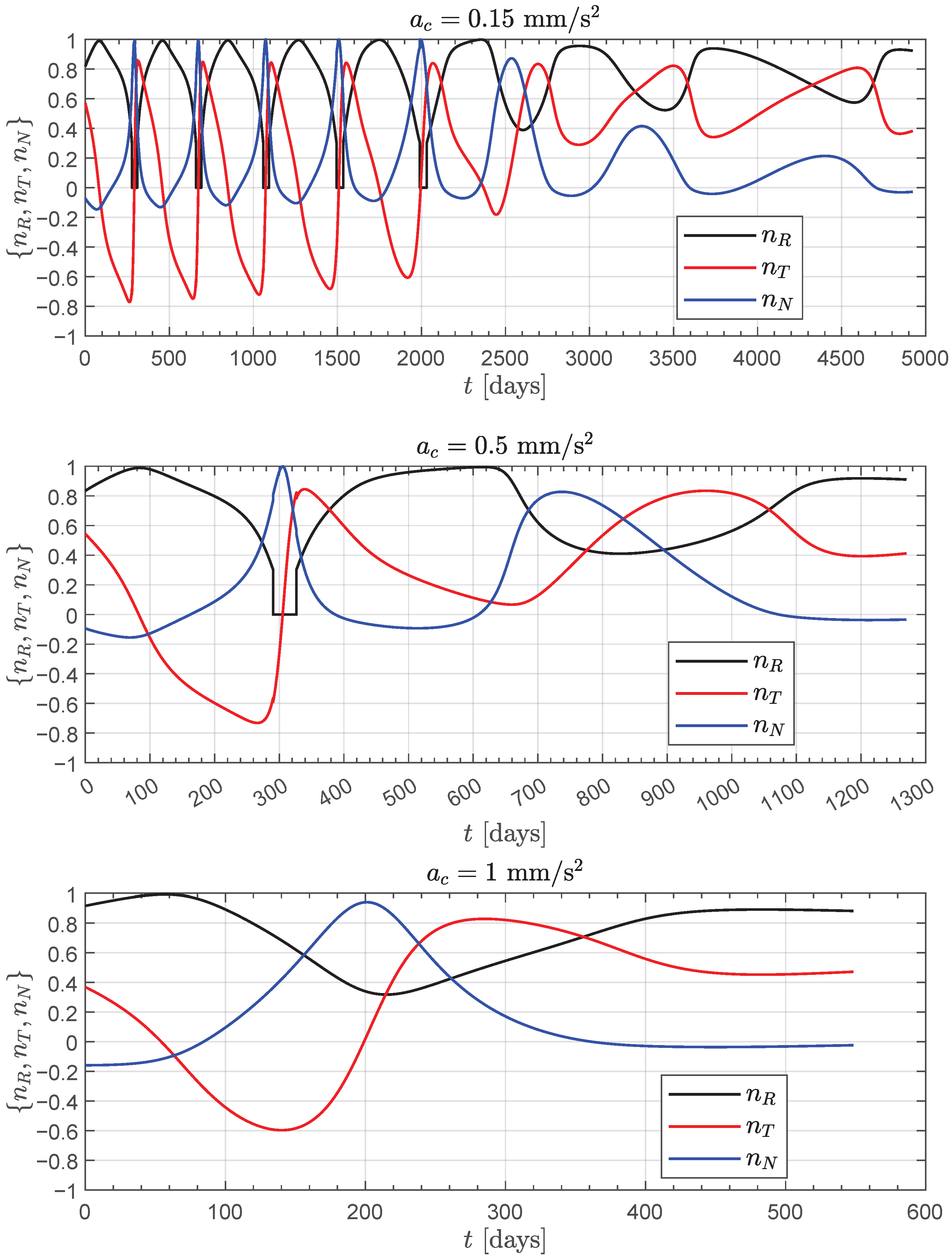
Figure 5 shows the temporal evolution of the three components of the normal unit vector n ^ in the RTN frame for selected values of the characteristic acceleration. Specifically, n R is the radial component, n T the transverse component, and n N the normal component of n ^ , which defines the orientation of the sail membrane. As expected, the plots in Figure 5 indicate that the optimal guidance law becomes increasingly complex as the value of a c decreases and, consequently, the number of revolutions N increases.

2.3. Optimized Trajectories in the ECT Scenario

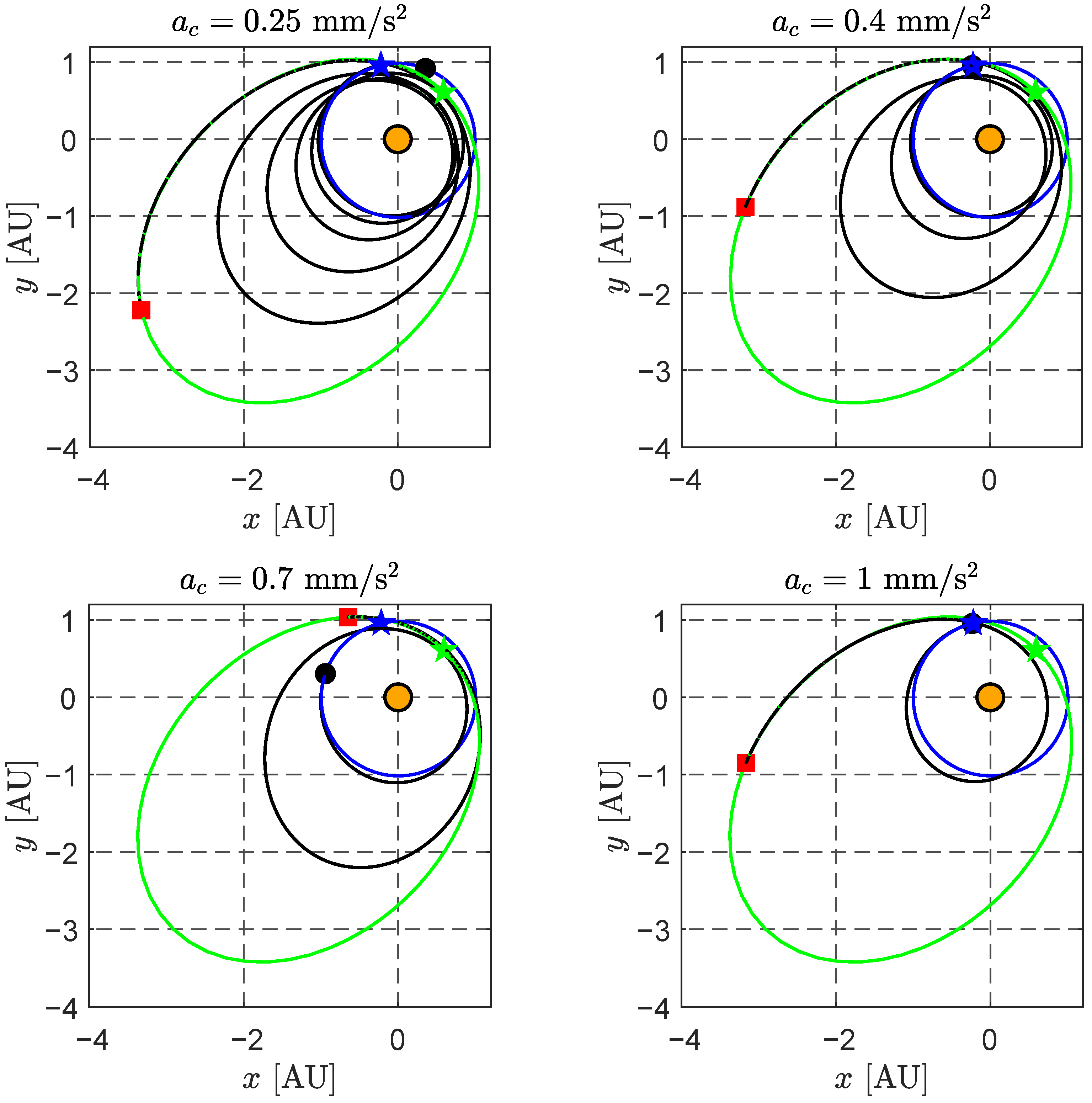
The results obtained from the EFT study are used to identify, for a given value of the characteristic acceleration, the most suitable launch window in the ECT. In this context, and based on Figure 3, a value of a c 0.25 mm / s 2 is considered, in order to limit the flight time to approximately 8 years or, accounting for performance degradation (i.e., the increase in flight time) due to ephemeris constraints, to a few additional months.
The analysis of the optimal launch window was conducted over a 10 year interval, from 1 January 2025 to 1 January 2035. Within this time frame—corresponding to a modified Julian date (MJD) range from 60,676 to 64,328—the scan step was set to 10 days . The results of the sailcraft transfer performance in the ECT are summarized in Table 3 as a function of the characteristic acceleration. Specifically, Table 3 reports the minimum flight time constrained by the selected launch date, along with the corresponding arrival date. As expected, the value of Δ t obtained in the ECT is greater than that found in the EFT study.
The optimal transfer trajectory of the sailcraft, as a function of the characteristic acceleration, is shown in Figure 6. This figure also highlights several similarities with the trajectory shapes observed in the EFT case (see Figure 4).
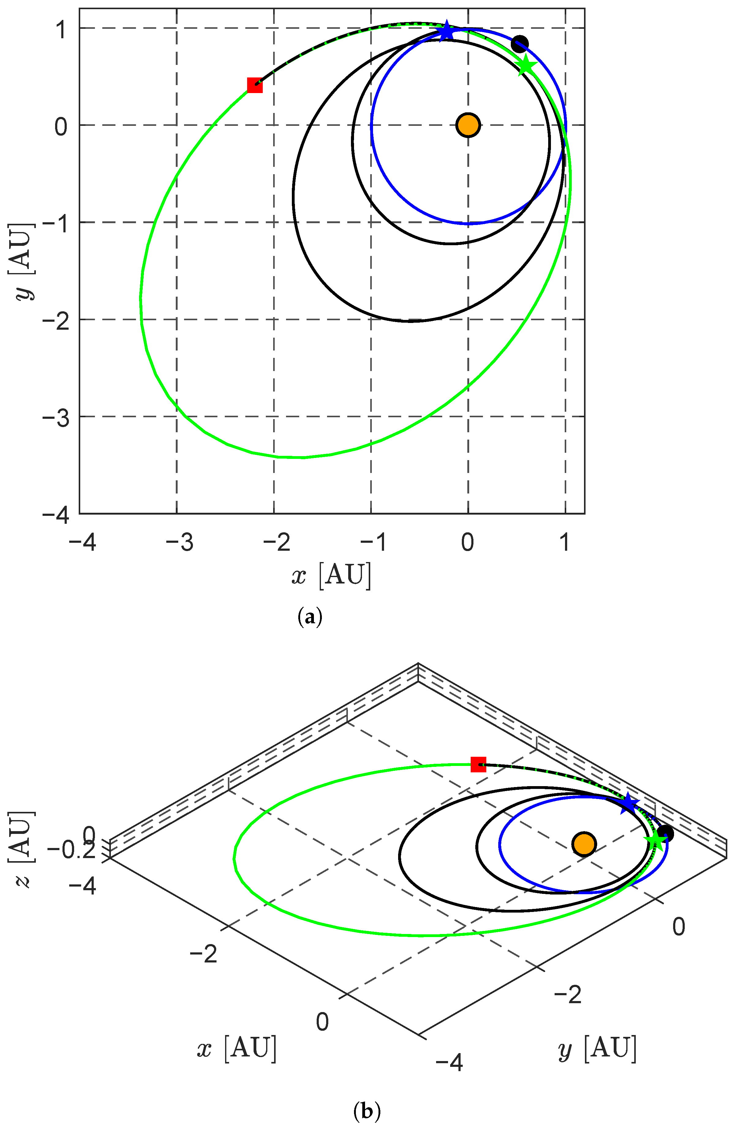
The results obtained from the ECT analysis, summarized in Table 3, indicate that the scenario with a c = 0.5 mm / s 2 and a launch date of 20 November 2025 yields an optimal (constrained) flight time that essentially coincides with the minimum value obtained in the EFT study, namely 1270 days . This noteworthy combination of characteristic acceleration and launch date is now considered in detail to illustrate a potential case study.

2.4. Representative Mission Scenario

Consider a sailcraft with a c = 0.5 mm / s 2 and a launch date of 20 November 2025 (corresponding to MJD 60,999). In this case, the ephemeris-constrained transfer yields an optimal flight time of 1270 days , i.e., approximately 3.5 years . The sailcraft’s true anomaly along the parking (or target) orbit at the beginning (or end) of the interplanetary transfer is approximately 314 deg (or 124 deg ), respectively. The optimal trajectory is shown in Figure 7, which also illustrates the three-dimensional nature of the transfer, involving two complete revolutions around the Sun.
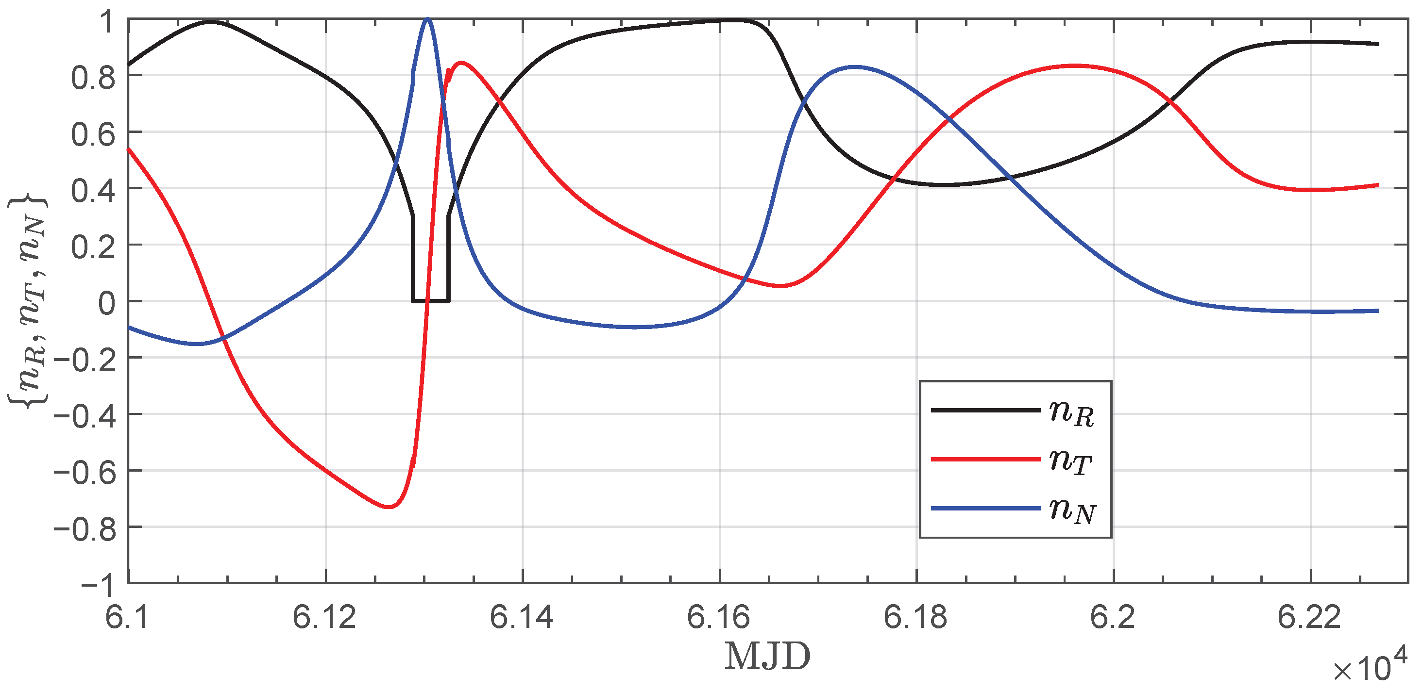
Figure 8 shows the temporal evolution of the three components of the normal unit vector n ^ in the RTN frame. Note that the shape of the graphs in Figure 8 closely resembles that shown in the central portion of Figure 5.
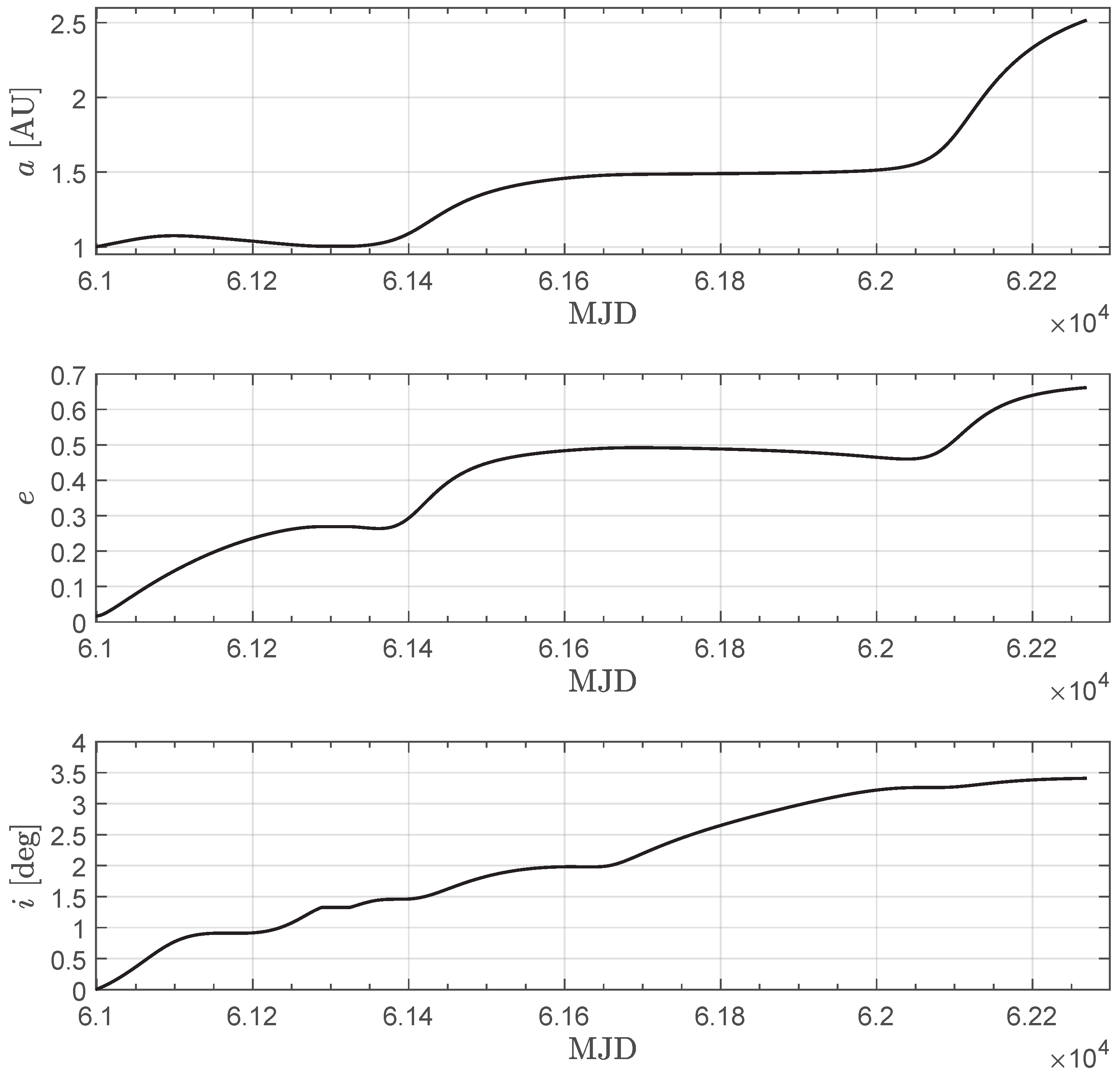
Finally, Figure 9 shows the variation of the semimajor axis, eccentricity, and inclination of the sailcraft’s osculating orbit throughout the transfer. Note that the values of these three orbital elements vary between those of Earth’s orbit and those of the heliocentric orbit of asteroid 2024 YR4.

3. Conclusions

This paper analyzed the transfer trajectories of an interplanetary spacecraft propelled by a solar sail on a rendezvous mission to the recently discovered asteroid 2024 YR4. The preliminary study was conducted in two phases, progressively introducing ephemeris constraints into the mathematical model and orbital simulations. The simulations revealed a promising launch window that enables an optimal transfer to the asteroid. However, the required sailcraft performance in that scenario cannot yet be achieved with current technology. Specifically, a transfer allowing arrival at the target asteroid before its potentially hazardous close encounter with Earth—expected at the end of 2032—would require a solar sail with a characteristic acceleration of at least 0.5 mm / s 2 .
The analysis presented in this paper does not account for uncertainties related to the transfer, such as errors in estimating the properties of the reflective membrane or the influence of orbital perturbations. These factors, which could significantly degrade performance, may be addressed in future refinements of the study, representing a natural extension of the present work.

Funding

This research received no external funding.

Institutional Review Board Statement

Not applicable.

Informed Consent Statement

Not applicable.

Data Availability Statement

The original contributions presented in the study are included in the article; further inquiries can be directed to the corresponding author.

Conflicts of Interest

The author declares no conflicts of interest.

Abbreviations

The following abbreviations and symbols are used in this manuscript:
Acronyms
ACS3Advanced Composite Solar Sail System
ECTephemeris-constrained transfer
EFTephemeris-free transfer
IKAROSInterplanetary Kite-craft Accelerated by Radiation Of the Sun
JAXAJapan Aerospace Exploration Agency
JPLJet Propulsion Laboratory
MEOEmodified equinoctial orbit element
MJDmodified Julian date
NASANational Aeronautics and Space Administration
PHAPotentially Hazardous Asteroid
RTNradial-transverse-normal orbital reference frame
sailcraftsolar sail-propelled spacecraft
asemimajor axis [AU]
a c characteristic acceleration [mm/s ­ 2 ]
a propulsive acceleration vector [mm/s ­ 2 ]
b vector; see Equation (A6)
eeccentricity
iorbital inclination [deg]
Mmean anomaly [deg]
M matrix; see Equation (A6)
Nnumber of complete revolutions around the Sun
n ^ normal unit vector
n N normal component of n ^
n R radial component of n ^
n T transverse component of n ^
{ p , f , g , h , k , L } modified equinoctial orbit elements
r sailcraft’s position vector [AU]
r ^ radial unit vector
rSun-sailcraft distance [AU]
ttime [days]
v sailcraft’s velocity vector [km/s]
Δ t minimum flight time [days]
ν true anomaly [deg]
λ adjoint vector
ω argument of perihelion [deg]
Ω right ascension of the ascending node [deg]
Subscripts
0initial
ffinal
Superscripts
optimal value
·temporal derivative
unit vector

Appendix A

This appendix summarizes the mathematical model used to describe the sailcraft’s heliocentric dynamics and to optimize the interplanetary transfer trajectory. In particular, this section is based on the model adopted in recent literature [30] to investigate solar sail performance in a mission toward comet 29P/Schwassmann-Wachmann 1. Interested readers are referred to that reference [30] for additional information about the approach employed to study the transfer scenario.
Assuming that, during the interplanetary flight, the sailcraft is subjected to the Sun’s gravitational attraction and to the solar sail-induced propulsive acceleration vector a , the heliocentric dynamics of the spacecraft is described by the classical differential equations:
r ˙ = v , v ˙ = μ r 3 r + a
where r R 3 × 1 is the sailcraft’s position vector, v R 3 × 1 is the sailcraft’s velocity vector, and a is given by Equation (1) as a function of the (control) unit vector n ^ R 3 × 1 and the performance parameter a c .
Using the six modified equinoctial orbit elements (MEOEs) { p , f , g , h , k , L } introduced by Walker [47], the components of the sailcraft’s position and velocity vectors in a typical Cartesian heliocentric-ecliptic reference frame [48] can be expressed as follows:
r = r 1 + h 2 + k 2 1 + h 2 k 2 cos L + 2 h k sin L 1 h 2 + k 2 sin L + 2 h k cos L 2 h sin L 2 k cos L
v = μ / p 1 + h 2 + k 2 sin L + g h 2 k 2 + 1 2 h k cos L + f cos L + f h 2 k 2 1 + 2 h k sin L + g 2 h cos L + f 2 k sin L + g
while the solar distance is given by r = p / 1 + f , cos L + g , sin L . The classical orbital elements are obtained from the MEOEs through the following equations:
a = p 1 f 2 g 2 , e = f 2 + g 2 , i = 2 arctan h 2 + k 2 , sin ω = g h f k , cos ω = f h + g k , sin Ω = k , cos Ω = h , ν = L Ω ω
The sailcraft’s heliocentric dynamics can then be expressed in terms of the temporal variation of the state vector x [ p , f , g , h , k , , L ] T R 6 × 1 , using the procedure proposed by Betts [49]. The resulting formulation is:
x ˙ = M a + b
where the components of vector a R 3 × 1 are expressed in the RTN reference frame sketched in Figure 2, while M R 6 × 3 and b R 6 × 1 are defined as:
M = 0 2 p 1 + f cos L + g sin L p μ 0 sin L p μ 2 + f cos L + g sin L cos L + f 1 + f cos L + g sin L p μ g h sin L k cos L 1 + f cos L + g sin L p μ cos L p μ 2 + f cos L + g sin L sin L + g 1 + f cos L + g sin L p μ f h sin L k cos L 1 + f cos L + g sin L p μ 0 0 1 + h 2 + k 2 cos L 2 1 + f cos L + g sin L p μ 0 0 1 + h 2 + k 2 sin L 2 1 + f cos L + g sin L p μ 0 0 h sin L k cos L 1 + f cos L + g sin L p μ , b = 0 0 0 0 0 μ p 1 + f cos L + g sin L p 2
The previous equations are employed to formulate the Hamiltonian function H R of this problem:
H = ( M a ) · λ + b · λ
where λ R 6 × 1 is the adjoint vector, whose temporal derivative is given by the Euler–Lagrange equations, namely:
λ ˙ = H x
The expression of H is also used, according to ref. [50], to determine the optimal control unit vector n ^ R 3 × 1 , given by:
n ^ = n ^ = arg   max n ^ ( M a ) · λ
Finally, the differential system formed by Equations (A5) and (A8) is completed by boundary conditions defined by departure from (or arrival at) Earth’s orbit (or the target asteroid’s orbit), along with the transversality condition [51]. This leads to a boundary value problem, which is solved using rather standard approaches, such as a single shooting procedure [45].

References

  1. Vichi, V.; Tommei, G. Exploring the potential of neural networks in early detection of potentially hazardous near-earth objects. Celest. Mech. Dyn. Astron. 2025, 137, 17. [Google Scholar] [CrossRef]
  2. Lay, O.; Masiero, J.; Grav, T.; Mainzer, A.; Masci, F.; Wright, E. Asteroid Impact Hazard Warning from the Near-Earth Object Surveyor Mission. Planet. Sci. J. 2024, 5, 149. [Google Scholar] [CrossRef]
  3. Peng, C.; Zhang, R.; Gao, Y. Trajectory Design of Potentially Hazardous Asteroid Exploration with Reusable Probes from Cislunar Space. Aerospace 2024, 11, 546. [Google Scholar] [CrossRef]
  4. Sears, D.W.G. The Explored Asteroids: Science and Exploration in the Space Age. Space Sci. Rev. 2015, 194, 139–235. [Google Scholar] [CrossRef]
  5. Vardaxis, G.; Wie, B. Near-Earth object intercept trajectory design for planetary defense. Acta Astronaut. 2014, 101, 1–15. [Google Scholar] [CrossRef]
  6. Aslani Khiavi, S.; Jafari-Nadoushan, M. Efficient approach of painting asteroids for planetary defense using network data envelopment analysis. Adv. Space Res. 2025, 75, 3230–3241. [Google Scholar] [CrossRef]
  7. Bolin, B.T.; Hanuš, J.; Denneau, L.; Bonamico, R.; Abron, L.M.; Delbo, M.; Ďurech, J.; Jedicke, R.; Alcorn, L.Y.; Cikota, A.; et al. The Discovery and Characterization of Earth-crossing Asteroid 2024 YR4. Astrophys. J. Lett. 2025, 984, L25. [Google Scholar] [CrossRef]
  8. Binzel, R.P. The Torino Impact Hazard Scale. Planet. Space Sci. 2000, 48, 297–303. [Google Scholar] [CrossRef]
  9. Smirnov, E.A. Chaotic diffusion and transient resonance captures of the near-Earth asteroid 2024 YR4. Astron. Astrophys. 2025, 699, A26. [Google Scholar] [CrossRef]
  10. Reddy, V.; Kelley, M.S.; Dotson, J.; Farnocchia, D.; Erasmus, N.; Polishook, D.; Masiero, J.; Benner, L.A.M.; Bauer, J.; Alarcon, M.R.; et al. Apophis Planetary Defense Campaign. Planet. Sci. J. 2022, 3, 123. [Google Scholar] [CrossRef]
  11. Norwood, J.; Hammel, H.; Milam, S.; Stansberry, J.; Lunine, J.; Chanover, N.; Hines, D.; Sonneborn, G.; Tiscareno, M.; Brown, M.; et al. Solar System Observations with theJames Webb Space Telescope. Publ. Astron. Soc. Pac. 2016, 128, 025004. [Google Scholar] [CrossRef]
  12. Rivkin, A.S.; Marchis, F.; Stansberry, J.A.; Takir, D.; Thomas, C. Asteroids and the James Webb Space Telescope. Publ. Astron. Soc. Pac. 2016, 128, 018003. [Google Scholar] [CrossRef]
  13. Thomas, C.A.; Abell, P.; Castillo-Rogez, J.; Moskovitz, N.; Mueller, M.; Reddy, V.; Rivkin, A.; Ryan, E.; Stansberry, J. Observing Near-Earth Objects with the James Webb Space Telescope. Publ. Astron. Soc. Pac. 2016, 128, 018002. [Google Scholar] [CrossRef]
  14. Morelli, A.C.; Mannocchi, A.; Giordano, C.; Ferrari, F.; Topputo, F. Initial Trajectory Assessment of a low-thrust option for the RAMSES Mission to (99942) Apophis. Adv. Space Res. 2024, 73, 4241–4253. [Google Scholar] [CrossRef]
  15. Megia, V.H.; Ho, T.M.; Grundmann, J.T.; Noeker, M. Modeling and control techniques for landing on (99942) Apophis: An analysis of a mission scenario. Acta Astronaut. 2025, 235, 185–194. [Google Scholar] [CrossRef]
  16. Izzo, D. Optimization of Interplanetary Trajectories for Impulsive and Continuous Asteroid Deflection. J. Guid. Control Dyn. 2007, 30, 401–408. [Google Scholar] [CrossRef]
  17. Mengali, G.; Quarta, A.A. Rapid Solar Sail Rendezvous Missions to Asteroid 99942 Apophis. J. Spacecr. Rocket. 2009, 46, 134–140. [Google Scholar] [CrossRef]
  18. Foster, C.; Bellerose, J.; Mauro, D.; Jaroux, B. Mission concepts and operations for asteroid mitigation involving multiple gravity tractors. Acta Astronaut. 2013, 90, 112–118. [Google Scholar] [CrossRef]
  19. Quarta, A.A. Thrust model and trajectory design of an interplanetary CubeSat with a hybrid propulsion system. Actuators 2024, 13, 384. [Google Scholar] [CrossRef]
  20. Fu, B.; Sperber, E.; Eke, F. Solar sail technology—A state of the art review. Prog. Aerosp. Sci. 2016, 86, 1–19. [Google Scholar] [CrossRef]
  21. Gong, S.; Macdonald, M. Review on solar sail technology. Astrodynamics 2019, 3, 93–125. [Google Scholar] [CrossRef]
  22. Tsuda, Y.; Mori, O.; Funase, R.; Sawada, H.; Yamamoto, T.; Saiki, T.; Endo, T.; Yonekura, K.; Hoshino, H.; Kawaguchi, J. Achievement of IKAROS—Japanese deep space solar sail demonstration mission. Acta Astronaut. 2013, 82, 183–188. [Google Scholar] [CrossRef]
  23. Funase, R.; Kawaguchi, J.; Mori, O.; Sawada, H.; Tsuda, Y. IKAROS, A solar sail demonstrator and its application to trojan asteroid exploration. In Proceedings of the 53rd AIAA/ASME/ASCE/AHS/ASC Structures, Structural Dynamics and Materials Conference, Honolulu, HI, USA, 23–26 April 2012. [Google Scholar] [CrossRef]
  24. Minervino Amodio, A.; Visser, P.; Heiligers, J. Dynamical modelling of NASA’s ACS3 solar sail mission. Aerosp. Sci. Technol. 2025, 161, 110146. [Google Scholar] [CrossRef]
  25. Wilkie, W.K.; Fernandez, J.M.; Stohlman, O.R.; Schneider, N.R.; Dean, G.D.; Kang, J.H.; Warren, J.E.; Cook, S.M.; Brown, P.L.; Denkins, T.C.; et al. An overview of the NASA advanced composite solar sail (ACS3) technology demonstration project. In Proceedings of the AIAA SciTech Forum, Virtual event, 11–21 January 2021. [Google Scholar] [CrossRef]
  26. Berthet, M.; Schalkwyk, J.; Çelik, O.; Sengupta, D.; Fujino, K.; Hein, A.M.; Tenorio, L.; Cardoso dos Santos, J.; Worden, S.P.; Mauskopf, P.D.; et al. Space sails for achieving major space exploration goals: Historical review and future outlook. Prog. Aerosp. Sci. 2024, 150, 101047. [Google Scholar] [CrossRef]
  27. Zhao, P.; Wu, C.; Li, Y. Design and application of solar sailing: A review on key technologies. Chin. J. Aeronaut. 2023, 36, 125–144. [Google Scholar] [CrossRef]
  28. Pezent, J.B.; Sood, R.; Heaton, A.; Miller, K.; Johnson, L. Preliminary trajectory design for NASA’s Solar Cruiser: A technology demonstration mission. Acta Astronaut. 2021, 183, 134–140. [Google Scholar] [CrossRef]
  29. McInnes, C.R. Solar Sailing: Technology, Dynamics and Mission Applications; Springer: Berlin, Germany, 1999; Chapter 2, pp. 46–53. [Google Scholar] [CrossRef]
  30. Quarta, A.A.; Abu Salem, K.; Palaia, G. Solar sail transfer trajectory design for comet 29P/Schwassmann-Wachmann 1 rendezvous. Appl. Sci. 2023, 13, 9590. [Google Scholar] [CrossRef]
  31. Wang, J.; Cheng, Z.; He, G.; Yuan, H. Uncertainty characterization of solar sail thrust with a multiscale modeling method. Adv. Space Res. 2025, 75, 5640–5655. [Google Scholar] [CrossRef]
  32. Johnson, L.; Akhavan-Tafti, M.; Sood, R.; Szabo, A.; Thomas, H.D. Space Weather Investigation Frontier (SWIFT) Mission Concept: Continuous Distributed Observations of Geo-Effective, Heliospheric Structures from the Vantage Points of Sun-Earth L1 and Sub-L1. In Proceedings of the 75th International Astronautical Congress (IAC), Milan, Italy, 14–18 October 2024. [Google Scholar]
  33. Johnson, L.; Akhavan-Tafti, M.; Sood, R.; Szabo, A.; Thomas, H.D. Space Weather Investigation Frontier (SWIFT) Mission Concept: Continuous, Distributed Observations of Heliospheric Structures from the Vantage Points of Sun-Earth L1 and Sub-L1. Acta Astronaut. 2025, 236, 684–691. [Google Scholar] [CrossRef]
  34. Boni, L.; Bassetto, M.; Quarta, A.A. Characterization of a Solar Sail Membrane for Abaqus-Based Simulations. Aerospace 2024, 11, 151. [Google Scholar] [CrossRef]
  35. Luo, Y.z.; Yang, Z. A review of uncertainty propagation in orbital mechanics. Prog. Aerosp. Sci. 2017, 89, 23–39. [Google Scholar] [CrossRef]
  36. Niccolai, L.; Anderlini, A.; Mengali, G.; Quarta, A.A. Effects of optical parameter measurement uncertainties and solar irradiance fluctuations on solar sailing. Adv. Space Res. 2021, 67, 2784–2794. [Google Scholar] [CrossRef]
  37. Bate, R.R.; Mueller, D.D.; White, J.E. Fundamentals of Astrodynamics; Dover Publications: New York, NY, USA, 1971; Chapters 4 & 7, pp. 212–222 & 321–355. ISBN 0-486-60061-0. [Google Scholar]
  38. Moiseev, Y.A.; Emelyanov, N.V. Ephemeris Theories JPL DE, INPOP, and EPM. Astron. Rep. 2024, 68, 1098–1118. [Google Scholar] [CrossRef]
  39. Lisse, C.M.; Steckloff, J.K.; Prialnik, D.; Womack, M.; Harrington Pinto, O.; Sarid, G.; Fernandez, Y.R.; Schambeau, C.A.; Kareta, T.; Samarasinha, N.H.; et al. 29P/Schwassmann–Wachmann 1: A Rosetta Stone for Amorphous Water Ice and CO ↔ CO2 Conversion in Centaurs and Comets? Planet. Sci. J. 2022, 3, 251. [Google Scholar] [CrossRef]
  40. Georgevic, R.M. The solar radiation pressure force and torques model. In Proceedings of the Astrodynamics Specialists Conference, Ft. Lauderdale, FL, USA, 17–19 August 1971. [Google Scholar]
  41. Mengali, G.; Quarta, A.A. Optimal three-dimensional interplanetary rendezvous using nonideal solar sail. J. Guid. Control Dyn. 2005, 28, 173–177. [Google Scholar] [CrossRef]
  42. Heaton, A.F.; Artusio-Glimpse, A.B. An Update to the NASA Reference Solar Sail Thrust Model. In Proceedings of the AIAA Space and Astronautics Forum and Exposition (AIAA SPACE 2015), Pasadena, CA, USA, 31 August–2 September 2015. [Google Scholar]
  43. Stengel, R.F. Optimal Control and Estimation; Dover Books on Mathematics, Dover Publications, Inc.: New York, NY, USA, 1994; pp. 222–254. ISBN 978-0486682006. [Google Scholar]
  44. Shampine, L.F.; Reichelt, M.W. The MATLAB ODE Suite. SIAM J. Sci. Comput. 1997, 18, 1–22. [Google Scholar] [CrossRef]
  45. Yang, W.Y.; Cao, W.; Kim, J.; Park, K.W.; Park, H.H.; Joung, J.; Ro, J.S.; Hong, C.H.; Im, T. Applied Numerical Methods Using MATLAB; John Wiley & Sons, Inc.: Hoboken, NJ, USA, 2020; Chapter 3 and 6, pp. 158–165, 312. [Google Scholar]
  46. Spencer, D.A.; Johnson, L.; Long, A.C. Solar sailing technology challenges. Aerosp. Sci. Technol. 2019, 93, 105276. [Google Scholar] [CrossRef]
  47. Walker, M.J.H.; Ireland, B.; Owens, J. A set of modified equinoctial orbit elements. Celest. Mech. 1985, 36, 409–419, Erratum in Celest. Mech. 1986, 38, 391–392. [Google Scholar] [CrossRef]
  48. Curtis, H.D. Orbital Mechanics for Engineering Students; Butterworth-Heinemann: Oxford, UK, 2020; Chapter 8, pp. 423–428. ISBN 978-0-08-102133-0. [Google Scholar] [CrossRef]
  49. Betts, J.T. Very low-thrust trajectory optimization using a direct SQP method. J. Comput. Appl. Math. 2000, 120, 27–40. [Google Scholar] [CrossRef]
  50. Ross, I.M. A Primer on Pontryagin’s Principle in Optimal Control; Collegiate Publishers: San Francisco, CA, USA, 2015; Chapter 2, pp. 127–129. [Google Scholar]
  51. Bryson, A.E.; Ho, Y.C. Applied Optimal Control; Hemisphere Publishing Corporation: New York, NY, USA, 1975; Chapter 2, pp. 71–89. ISBN 0-891-16228-3. [Google Scholar]
Figure 1. Flowchart of the trajectory optimization strategy.
Technologies 13 00373 g001
Figure 2. Sketch of the radial-transverse-normal (RTN) orbital reference frame.
Technologies 13 00373 g002
Figure 3. Function Δ t = Δ t ( a c ) obtained from the numerical study of the EFT. The corresponding numerical values of the minimum flight time are also listed in Table 2.
Technologies 13 00373 g003
Figure 4. Ecliptic projection of the optimal sailcraft transfer trajectories as a function of a c . Blue line → Earth’s orbit; black line → sailcraft trajectory; green line → asteroid 2024 YR4 orbit; black dot → departure point; red square → arrival point; blue star → Earth’s perihelion; green star → asteroid’s perihelion; orange dot → the Sun.
Technologies 13 00373 g004
Figure 5. Optimal guidance law, expressed as the temporal evolution of the components of n ^ in the RTN frame, as a function of the characteristic acceleration a c .
Technologies 13 00373 g005
Figure 6. Ecliptic projection of the optimal sailcraft transfer trajectories as a function of a c in an ECT. The legend is provided in the caption of Figure 4.
Technologies 13 00373 g006
Figure 7. Optimal transfer trajectory in an ECT for a c = 0.5 mm / s 2 , with a launch date of 20 November 2025. The legend is provided in the caption of Figure 4. (a) Ecliptic projection; (b) Three-dimensional view.
Technologies 13 00373 g007
Figure 8. Optimal guidance law in an ECT for a c = 0.5 mm / s 2 , with a launch date of 20 November 2025. The time axis is expressed in MJD.
Technologies 13 00373 g008
Figure 9. Temporal evolution of the semimajor axis (a), eccentricity (e), and inclination (i) of the sailcraft’s osculating orbit in an ECT with a c = 0.5 mm / s 2 and a launch date of 20 November 2025.
Technologies 13 00373 g009
Table 1. Classical orbital elements as of 1 January 2025, for the Keplerian orbits of Earth and asteroid 2024 YR4. The data were retrieved from JPL’s Horizons system on 10 July 2025.
Celestial Bodya [AU]ei [deg] ω [deg] Ω [deg]M [deg]
Earth 1.00002 1.6712 × 10 2 3.248 × 10 3 288.490 174.441 357.618
2024 YR4 2.5172 6.6174 × 10 1 3.4089 134.361 271.371 9.765
Table 2. Results of the EFT as a function of the characteristic acceleration ( a c ), including the minimum flight time ( Δ t ), number of complete revolutions around the Sun (N), initial true anomaly ( ν 0 ), and final true anomaly ( ν f ).
a c [mm/s ­ 2 ] Δ t [Days]N ν 0 [deg] ν f [deg]
0.1549238303129
0.236166324127
0.25285957126
0.323234353126
0.3519263296127
0.4168337124
0.4514522263132
0.512702314124
0.5511532350122
0.61058224121
0.65983165119
0.78261267129
0.757471292123
0.86931311120
0.856491327119
0.96121341118
0.955781354118
154816118
Table 3. Results of the ECT as a function of the characteristic acceleration ( a c ), including the minimum flight time ( Δ t ), launch date, and arrival date (also expressed in terms of MJD).
a c [mm/s ­ 2 ] Δ t [days]MJD StartMJD ArrivalStart DateArrival Date
0.25309861,01064,1081 December 202526 May 2034
0.3232461,40863,7323 January 202715 May 2033
0.4175960,67962,4384 January 202529 October 2029
0.45156660,94762,51329 September 202512 January 2030
0.5127060,99962,26920 November 202513 May 2029
0.6113061,04662,1766 January 20269 February 2029
0.7105561,10262,1573 March 202621 January 2029
0.896161,43262,39327 January 202714 September 2029
0.983861,43262,27027 January 202714 May 2029
166061,77562,4355 January 202826 October 2029
Disclaimer/Publisher’s Note: The statements, opinions and data contained in all publications are solely those of the individual author(s) and contributor(s) and not of MDPI and/or the editor(s). MDPI and/or the editor(s) disclaim responsibility for any injury to people or property resulting from any ideas, methods, instructions or products referred to in the content.