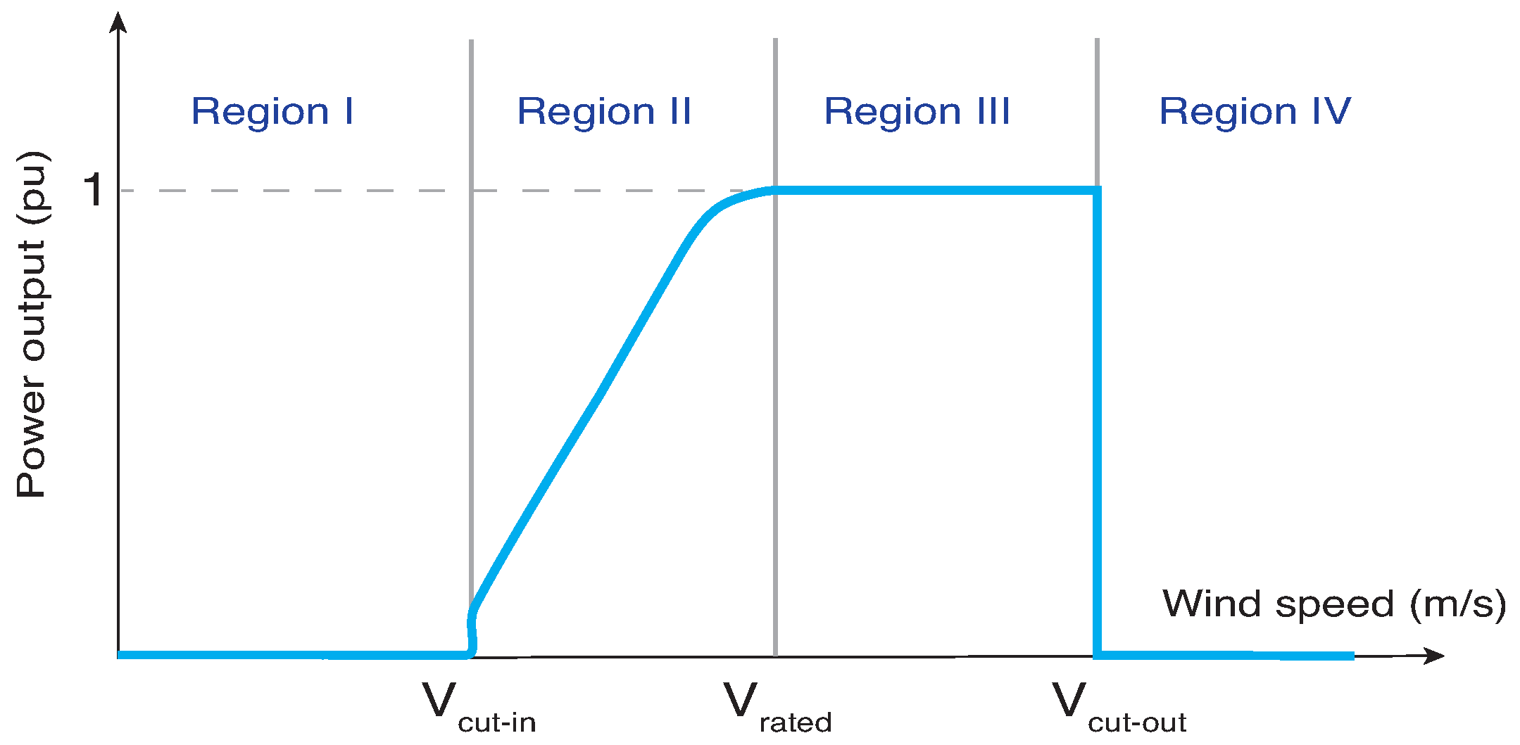
1. Introduction
According to the International Energy Agency’s (IEA) 2024 report, wind and solar power are expected to surpass nuclear power by 2026, and wind energy is projected to overtake hydroelectric power by 2030 [
1]. Currently, wind energy has become a vital part of the global energy transition, thanks to its lower greenhouse gas emissions, decreased dependence on fossil fuels, and its profitability [
2,
3]. Global installed wind power capacity has seen remarkable growth. For example, in 2024, 117 GW of wind capacity was installed, and with the current growth rate, 981 GW of new wind capacity could be added by 2030 [
4]. This rapid expansion presents technical challenges for grid operations, especially in maintaining frequency stability.
Traditionally, conventional synchronous machines have provided frequency support, as their inherent rotational inertia helps minimize rapid fluctuations in power. The oscillation equation defines the dynamics between frequency and active power, where an imbalance between generated power and load demand results in a rate of change in frequency (ROCOF), which is determined by the collective inertia of all generators connected to the grid during a contingency event [
5].
There are two main categories of grid support: (1) technologies related to voltage support and (2) frequency support [
6]. The principal relationship of voltage support is with the ability to inject or absorb reactive power at the point of interconnection or point of common coupling (PCC) [
7]. In contrast, frequency support is linked with the ability to modify the level of active power allocated to the grid, usually in response to external disturbances [
8].
It is crucial to understand that current wind energy conversion systems (WECS) offer a wide variety of features that simplify their connection to the grid, enabling them to participate in grid support tasks [
8]. In this sense, current WECS, connected to the grid through power converters, decouple the rotating mass of the generator from the electrical grid and, therefore, reduce the effective inertia of the system [
9]. This inertia reduction has motivated the development of control strategies that enable wind turbines to actively participate in frequency regulation [
10]. This ability offers a first line of protection against contingency events by preventing successive failures that can cause the disconnection of large loads, generating units, or a combination of these.
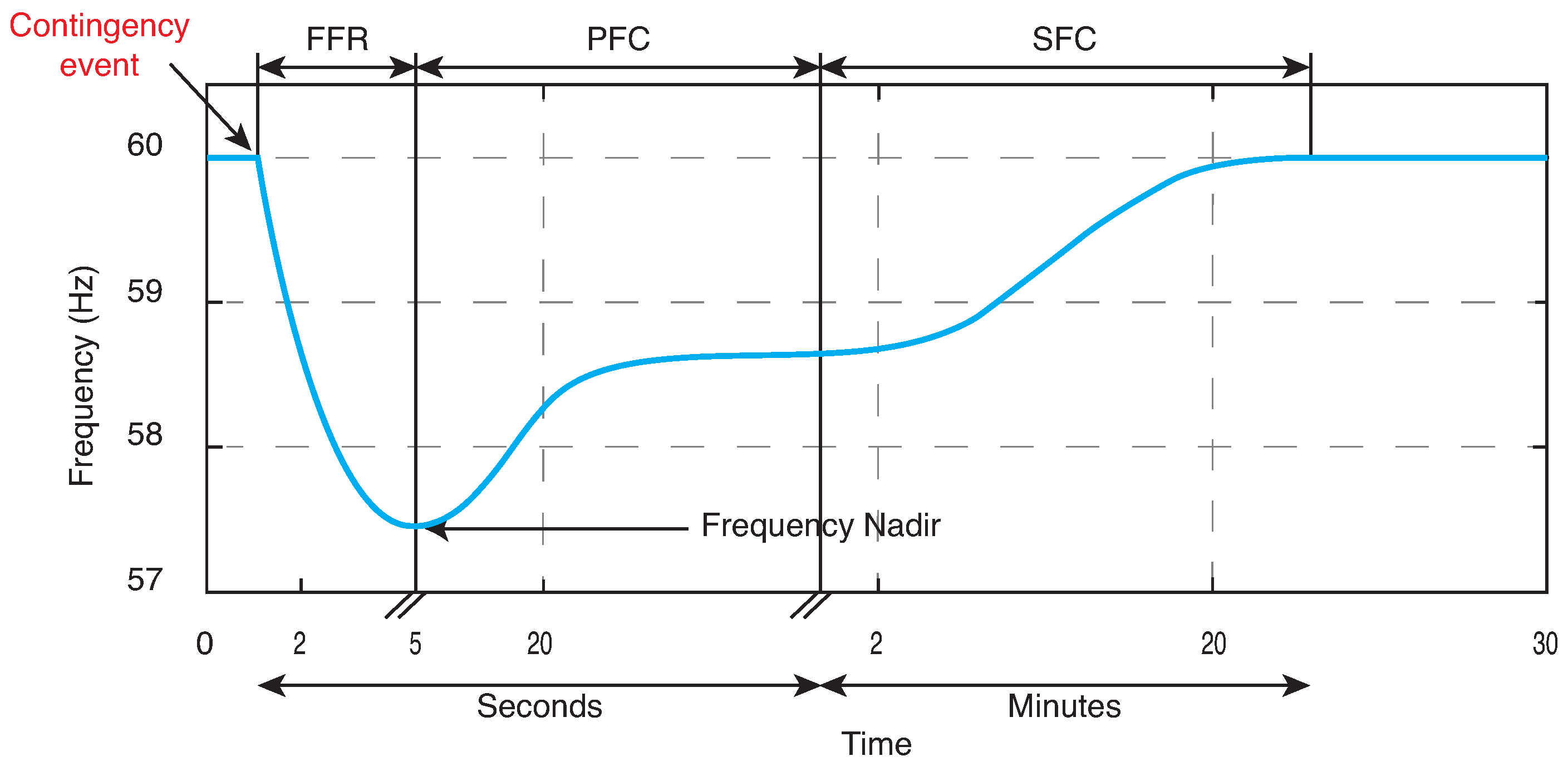
To illustrate the timescales involved in a contingency event,
Figure 1 shows the frequency dynamics of a power system in response to a disturbance—typically the loss of a generating unit. This event causes an imbalance between generation and demand, resulting in a decrease in the system’s frequency. The power system response is generally organized into three stages, as shown in
Figure 1: (1) fast frequency response (FFR); (2) primary frequency control (PFC); and (3) secondary frequency control (SFC). In a conventional power system, the immediate response of all generators directly connected to the grid is passive, consisting of a deceleration of their rotational motion. This process releases the kinetic energy stored in the rotating masses of the generators for a few seconds [
11] and is known as the inertial response. Inertial response is part of a broader concept called fast frequency response (FFR), designed to prevent frequency decay, reduce the initial rate of change, and increase the lowest frequency value, often called the frequency nadir [
12].
Taking advantage of the fact that the inertia constant H is similar between traditional generators and wind turbines, around 3 to 5 s [
13,
14], some research articles present inertial control systems that emulate the release of kinetic energy stored in the wind turbine blades to counteract frequency drops after severe contingencies [
7,
15,
16,
17,
18].
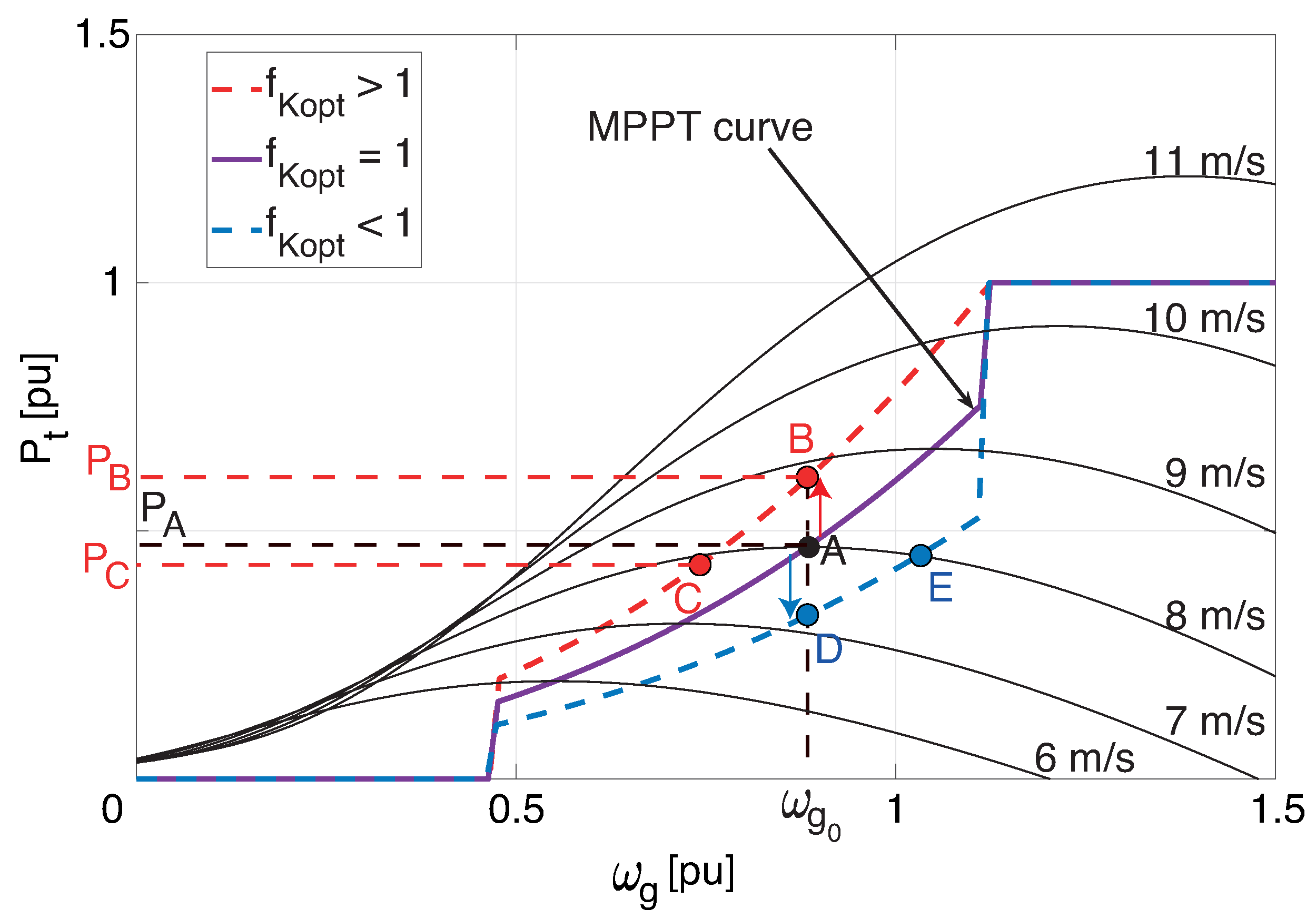
Typically, a wind turbine not involved in frequency regulation operates in maximum power point tracking (MPPT) mode, maximizing power capture under normal wind conditions. However, this strategy limits the available reserve power, so the inertial response can only be achieved by extracting kinetic energy from the rotor, which can increase mechanical loads and affect dynamic recovery [
19]. For this reason, many studies propose combining MPPT with virtual inertial control via the electronic converter to improve response to frequency disturbances [
20,
21]. De-loaded control intentionally introduces operation below the maximum power point, maintaining an active power reserve that can be released during a frequency drop [
22]. This strategy enhances the wind turbine’s ability to maintain system frequency without compromising the rotor’s mechanical integrity excessively. However, it implies a reduction in energy generated under normal conditions and, therefore, a slight economic loss [
22,
23]. Pitch control, on the other hand, is a well-established method in commercial turbines, traditionally used to regulate power output under wind conditions exceeding the nominal speed [
24]. Its use within inertial response strategies is based on the ability to modify aerodynamic power through rapid variations in blade angle, offering an effective tool for frequency control [
21]. However, its response is relatively slow to rapid system disturbances, and its intensive use can increase mechanical wear on the actuator [
24]. In general, recent literature suggests that the coordinated combination of these methods (MPPT, de-loaded, and pitch) allows achieving a balance between energy efficiency and the stability of the electrical system, maximizing the contribution of wind turbines to the global inertial response [
21,
25].
This paper introduces a virtual inertial control system based on fuzzy logic control (FLC) that adjusts the operating point of a wind turbine equipped with Doubly Fed Induction Generators (DFIG) in the
plane. The control principle is derived from an adaptation of the Extended Optimized Power Point Tracker (OPPTE) controller described in [
17]. The OPPTE method, which is an improved version of MPPT, allows maximizing the electrical power generated from the wind, maintaining a balance between energy efficiency and system stability, without incurring the generation losses or mechanical wear characteristic of discharge control and pitch control methods. OPPTE shifts the MPPT curve based on the deviation of the electrical frequency from its nominal value. This shift enables the extraction of kinetic energy from the wind turbine, allowing the wind power system to adjust its active power output to the electrical grid and provide frequency support services. The difference between the method proposed in this article and the OPPTE method lies in the significant improvement in the wind turbine’s inertial response, which is afforded by the flexibility of fuzzy control. These improvements have been reported in various engineering applications [
26,
27].
The adoption of a fuzzy logic-based approach is justified by its ability to effectively handle nonlinear systems subject to operating variations, where conventional control methods typically require precise models [
26]. Furthermore, recent literature shows that fuzzy controllers offer advantages in terms of flexibility, robustness, and dynamic performance compared to traditional linear strategies, particularly in applications requiring stable responses over an extended operating range [
28,
29,
30].
The added value of a fuzzy controller compared to other adaptive control techniques or intelligent control approaches lies in a combination of properties that are difficult to achieve simultaneously in alternative methods:
- 1.
Fuzzy logic offers a high level of interpretability, since its control laws are formulated using linguistic rules that can be easily analyzed, validated, and adjusted by process experts. This characteristic contrasts with techniques based on highly complex models or machine learning structures, which often operate as black boxes and require large volumes of data for training.
- 2.
Fuzzy controllers allow the direct incorporation of the operator’s heuristic knowledge, reducing dependence on a precise mathematical model and facilitating their application in systems with nonlinear or uncertain dynamics. Furthermore, the nature of fuzzy reasoning confers inherent robustness against external disturbances, enabling stable performance without incurring excessive computational costs.
- 3.
The modular structure of these controllers enables easy integration with modern optimization and learning techniques, preserving the system’s interpretability while enhancing its adaptive capabilities.
Taken together, these qualities position fuzzy control as a robust, versatile, and highly competitive alternative compared to other adaptive methods and intelligent control approaches. Below, a brief review of the state-of-the-art scientific work focused on fuzzy controllers that enable wind energy conversion systems to perform frequency regulation tasks is included.
1.1. Related Works
Inertial control in wind turbines seeks to provide frequency support to the electrical system, emulating the inertia of conventional synchronous machines. In other words, it enables the turbine to release or absorb active power in a controlled manner in response to changes in frequency.
Fuzzy logic control (FLC) provides an intuitive, robust, and flexible approach to designing a control system, particularly in variable conditions such as power systems with high renewable energy penetration. FLC offers the following advantages: (1) it handles linearity and uncertainty, and therefore, it does not require a precise mathematical model; (2) it offers an adaptive and flexible response; (3) it allows for the simple incorporation of multiple inputs without the need to linearize the system; and (4) it improves transient performance by reducing the frequency nadir and avoiding excessive or overly aggressive oscillations [
31].
There is a wide range of FLC applications for WECS or hybrid power systems, which include wind systems and energy storage devices (ESS). The authors of [
32] propose an active power smoothing method for a renewable system consisting of a WECS and an ESS based on supercapacitors. Using an FLC, the authors adjust the time constant of a transfer function based on variations in wind power and the state of charge (SOC) of the supercapacitors. The experimental result achieved was a 22% increase in wind power smoothing. In a similar hybrid system configuration (wind power and ESS), the authors of [
33] report a reduction of 0.04 Hz in the frequency nadir through the use of two FLCs, whose output signals weight a setpoint signal for electrical power.
The authors of [
34] propose a new coordinated control method for a low-voltage ride-through (LVRT) hybrid system. FLC improves the responses of pitch control, compared to conventional pitch control. The proposed method enables the ESS to operate almost at its nominal power (1 kWh), compared to the traditional control system, which contributes a maximum of 40% of its total capacity. Another frequency control strategy is reported in [
35], where the duty cycle of a boost converter is modified to control the voltage in the DC link of a wind turbine based on a Permanent Magnet Synchronous Generator (PMSG). The electrical system is composed of the WECS, a photovoltaic array, and an ESS. The result obtained is a constant voltage of 400 V and a frequency oscillation within a range of 49.85 to 50.05 Hz, compared to a conventional control whose frequency deviation oscillates in a range of 49.7 to 50.2 Hz.
A virtual synchronous generator (VSG) based on a lagging-lead compensator is described in [
36]. Using an FLC, the authors control the active power of a DFIG-WT based on the frequency deviation and its derivative. The proposed method achieves a frequency nadir of 49.91 Hz, compared to a system without VSG, which reaches 49.89 Hz. The disadvantage of this method is a second frequency dip, approximately 0.02 Hz, observed in the simulations. In this context, [
37] presents a method to prevent a second frequency dip when the wind turbine’s operating point returns to the pre-disturbance state. In constant wind speed simulations, the frequency deviation remains within the permissible range of 49.7 to 50.3 Hz. The model without frequency control needs additional spinning reserves to keep the grid frequency within the normal operating range.
Another approach to using FLC is to tune the gains of a PI control focused on frequency control. For example, in [
38], the authors perform active and reactive power control by using PI controllers tuned by an FLC. In addition, the authors minimize the error obtained from the controller by applying a continuous mixed p-norm (CMPN) adaptive filter. On the other hand, the authors of [
39] determine whether the harmonic distortions of current and voltages comply with the IEEE 519 standard. Through two FLCs, the gains of a PI controller that regulates the current in the quadrature axis
are modified. In investigations [
22,
40,
41,
42], different FLC-based droop control approaches are presented to ensure a certain percentage of power reserve (typically 10% of the WECS nominal power), thereby guaranteeing power reserves in the event of contingencies.
In [
43], an analogy of the operation of OPPTE through an FLC is presented. This controller relies on wind speed measurements and the rotational speed error, along with its derivatives. Therefore, a feedback compensation process and a high-pass filter are necessary. The observed results indicate a faster inertial response compared to conventional speed controllers.
1.2. Main Contribution
As highlighted in the state-of-the-art review, several approaches employ fuzzy logic controllers (FLCs) to provide frequency support in wind energy conversion systems (WECSs). Building on this foundation, the present work introduces an FLC-based inertial control strategy that synthesizes and extends the operation of the Extended Optimized Power Point Tracking (OPPTE) controller reported in [
17]. The proposed method makes two key contributions:
- 1.
Enhanced inertial response: Our proposed strategy significantly improves the inertial support of the WECS, yielding superior performance in terms of both frequency nadir reduction and mitigation of the rate of change of frequency (ROCOF), when compared to the baseline OPPTE method on which the fuzzy controller is built.
- 2.
Independence from wind speed measurements: Unlike the approach in [
43], the proposed method does not rely on real-time wind speed measurements. This feature removes a practical limitation, since reliance on wind speed sensors can hinder implementation due to calibration requirements, sensor inaccuracies, and dependence on specific turbine configurations [
44]. In practice, nacelle anemometers and nearby meteorological masts often provide wind signals affected by wakes, turbulence, and spatial mismatch, whereas rotor speed and grid frequency are local measurements that already reflect the actual wind loading on each turbine and can be used directly as inputs to the proposed controller.
3. The Proposed Controller
To enhance the inertial response of a WECS, this paper proposes an OPPTE-FLC scheme. The primary objective of the fuzzy controller is to compute the value of
based on selected input signals. To determine the appropriate inputs, their correlation with the control signal
is first evaluated. Equation (
2) defines the variables involved in calculating
, namely the frequency deviation, the rate of change of frequency (ROCOF), and the rotational speed of the wind turbine. Based on this formulation, a correlation matrix was constructed to identify suitable input candidates. In this study, data were obtained from a series of simulations conducted on a power system under dynamic conditions and a WECS with OPPTE. To generate the dataset, variations in wind speed were considered, ranging from 5 m/s to 10 m/s, allowing for analysis of the system’s behavior under different wind resource levels. Additionally, disturbances in the electrical system’s demand were introduced, consisting of increases of +5%, +10%, and +15% relative to the nominal load. These operating scenarios generate a representative dataset that captures the interaction between the control signal and the OPPTE controller inputs, ensuring that the analysis reflects a diverse range of power system conditions.
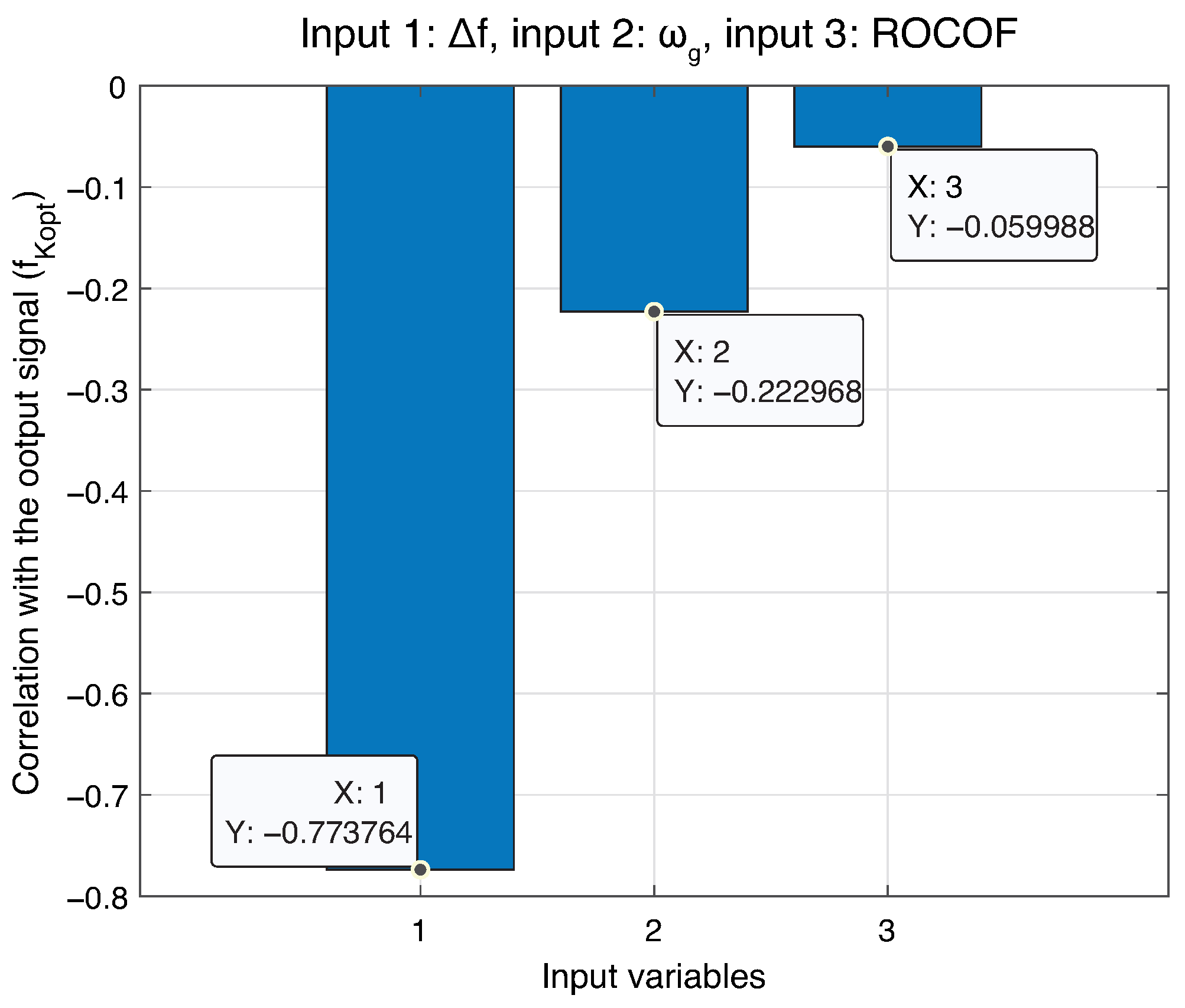
Figure 4 shows the results of the correlation matrix of all simulated scenarios. The frequency deviation
exhibits the strongest correlation with
, with a correlation coefficient of −0.7738. This negative correlation implies that as
decreases, the value of
increases. To further reduce the ROCOF of the system’s frequency response, the derivative of the frequency deviation was selected as a second input signal, consistent with approaches reported in [
35,
38,
47].
3.1. Fuzzy-Logic Controller Design
The fuzzy logic controller (FLC) employs two input variables: the frequency deviation and its derivative. The output signal corresponds to the computed value of
, which determines the displacement of the MPPT curve when a disturbance occurs in the grid frequency. Based on the simulated power system model, mentioned in
Section 3, the maximum and minimum values of the frequency deviation are ±0.004 Hz, while for its derivative (ROCOF) the limits are ±0.2 Hz/s. The output signal
ranges between 0.4 and 1.6, as reported in [
17].
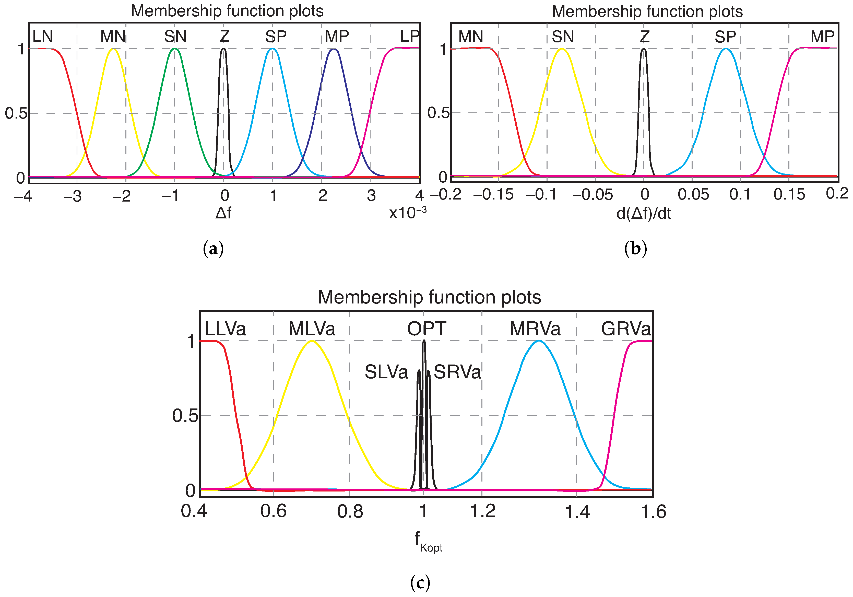
Figure 5a–c present the membership functions for the input and output signals. The input membership functions are labeled as large negative (LN), medium negative (MN), small negative (SN), zero (Z), small positive (SP), medium positive (MP), and large positive (LP). For the output membership functions, the central value (
= 1) corresponds to the optimum (OPT) label, representing the case where no control action is required. Values of (
< 1) are associated with the following labels: small left value (SLVa), medium left value (MLVa), and lower left value (LLVa). Conversely, values of (
> 1) correspond to small right value (SRVa), medium right value (MRVa), and greater right value (GRVa).
All membership functions close to the minimum and maximum limits are represented by the
zmf and
smf functions, respectively, while the other membership functions are Gaussian. These membership functions performed best in the simulations developed in this article.
Figure 5c shows that the SLVa and SRVa functions are located very close to the OPT function. The reason for this configuration is to ensure that the fuzzy controller takes corrective action in cases of small frequency deviations that occur in simulation scenarios with a wind series.
Table 1 summarizes the control rules implemented in the FLC. It is important to highlight that when
and
approach their maximum or minimum values, the corresponding output
increases accordingly.
The fuzzy controller rules were structured using an approach that aims to achieve strong control action when the input variables are close to their maximum values, and progressively softer action as these variables approach zero. In this sense, the rules were defined to guarantee a symmetrical response consistent with the physical nature of the input signals, allowing the controller to gradually reduce its intervention as the frequency deviation decreases, until it converges to the optimal operating point. This design criterion was adopted to ensure stable, predictable behavior compatible with the dynamics of the electrical system in the face of disturbances. Furthermore, the symmetrical structure of the rules facilitates consistency between the different fuzzy sets, ensuring that the controller responds proportionally to both positive and negative variations in the input signals.
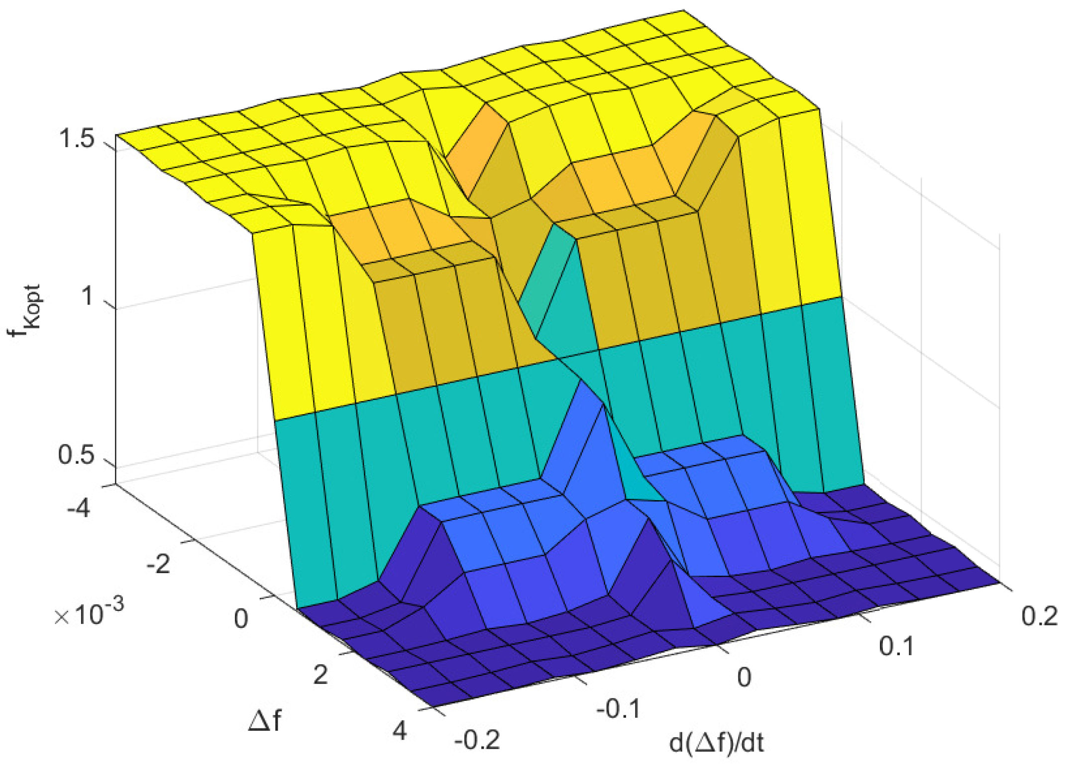
Figure 6 illustrates the control surface, which reflects the nonlinear dynamics of the problem under consideration. The surface highlights how the output
varies as a function of the frequency deviation
and its derivative
, capturing the adaptive behavior of the fuzzy logic controller in response to different disturbance conditions. A smooth, continuous surface is obtained, ensuring that the controller provides gradual transitions between control actions rather than abrupt changes, which is a key advantage of fuzzy inference compared to conventional rule-based or linear controllers.
Figure 7 presents the general block diagram of the proposed FLC. As shown, the frequency deviation is represented as the error signal (e), while its derivative serves as the rate-of-change-of-error input. These two signals are processed through
fuzzification, which maps the crisp numerical inputs into linguistic variables defined by the membership functions described earlier. The fuzzy inference mechanism then evaluates the rule base (
Table 1) to determine the appropriate control action. Finally, a
defuzzification stage converts the fuzzy output into a crisp value of
, which dynamically shifts the MPPT curve in response to grid frequency disturbances. The new reference value for the wind turbine power is defined by the variable
, which depends on the output signal of the fuzzy controller, the optimization constant, and the rotational speed of the turbine.
This structure enables the controller to adapt its response according to both the magnitude and the derivative of frequency deviations. In practice, large and fast deviations trigger higher values of , thereby shifting the operating point more aggressively to inject additional active power. Conversely, when deviations are small or slow, the output remains close to unity, maintaining operation near the optimal MPPT curve. This behavior ensures, as it was seen in the simulation results, that the system provides effective inertial support without compromising energy capture under normal operating conditions.
3.2. Determination of Membership Function Parameters
This section provides a detailed description of the proposed FLC’s configuration, with a focus on the design of its membership functions. As indicated in
Section 3.1, the use of the Z-shaped membership function (zmf) and S-shaped membership function (smf) is particularly suitable for the boundaries of the input and output variables, due to their smooth and monotonic transitions [
48]. The parameters of the zmf function are: a: point where the curve begins to descend from its maximum value (1), and b: point where the curve reaches its minimum value (0). The parameters of the smf function are: a: point where the curve begins to ascend from its minimum value (0), and b: point where the curve reaches its maximum value (1).
Table 2 presents the parameters used for the LN, LP, MN, MP, LLVa, and GRVa membership functions.
The remaining membership functions are of the Gaussian type (gaussmf), which allow for a smooth, symmetric, and mathematically consistent representation of the inherent variability in the system’s signals. These functions model fuzzy sets with uncertainty concentrated around a typical or nominal value. The parameterization of the gaussmf functions depends on two values: the mean (c) and the standard deviation (
), providing an intuitive and flexible fit. This facilitates the definition of well-bounded sets with gradual overlaps between adjacent sets, improving the interpolation capabilities of the fuzzy inference system and contributing to a smoother response to variations in the inputs [
48].
The c parameter of the Gaussian membership functions was determined through a series of simulations in which it was scanned to identify the best response compared to the conventional OPPTE method. The simulation conditions correspond to a constant wind speed of 9 m/s and a load increase of 10% of its nominal value. The variation range of the c parameter associated with the SN and SP membership functions of the input signal
is from ±0.0016 to ±0.0008 in steps of ±0.0002. Negative values correspond to the c parameter of the SN function, while positive values of c correspond to the SP function. The simulations with the best results have a c value of ±0.001. Following the same procedure described previously, the value of the parameter c for the MN and MP membership functions was determined, with c ranging from ±0.003 to ±0.002 in steps of ±0.000275. The best response for these membership functions was obtained with c = ±0.00225. Instead, the range of variation in the parameter c for the SN and SP membership functions related to the
input signal is ±0.13 to ±0.055, in steps of ±0.015, yielding a better inertial response with c = ±0.085. Finally, the values of c for the SLVa, SRVa, MLVa, and MRVa membership functions that yielded the best results were: 0.99, 1.01, 0.7, and 1.3, respectively. The parameters of all Gaussian functions are presented in the
Table 3.
4. Simulation Results
The power system studied in [
49] serves as the reference framework for this article. As shown in
Figure 8, all wind generation in the isolated system is represented by a single 2.4 MW unit, while the island’s synchronous generation is modeled by a 2.439 MVA generator. The nominal system load is 2 MW, providing a balanced reference case for evaluating frequency response under disturbances.
The simulations presented in this article were conducted using MATLAB/Simulink. The parameters of the Simulink simulations are:
The proposed OPPTE-FLC control strategy is compared against two benchmarks: (i) the OPPTE inertial control method reported in [
17], and (ii) a baseline configuration without inertial control (NIC). These three cases are evaluated under a set of simulation scenarios designed to assess the dynamic performance of the system, with emphasis on frequency nadir reduction, ROCOF mitigation, and peak active power injection.
4.1. Results of Constant Wind Speed and Load Change Simulations
The first simulation scenario corresponds to a 100 s test with a constant wind speed of 9 m/s. At t = 50 s, a 20% increase in the nominal system load is introduced as the contingency event.
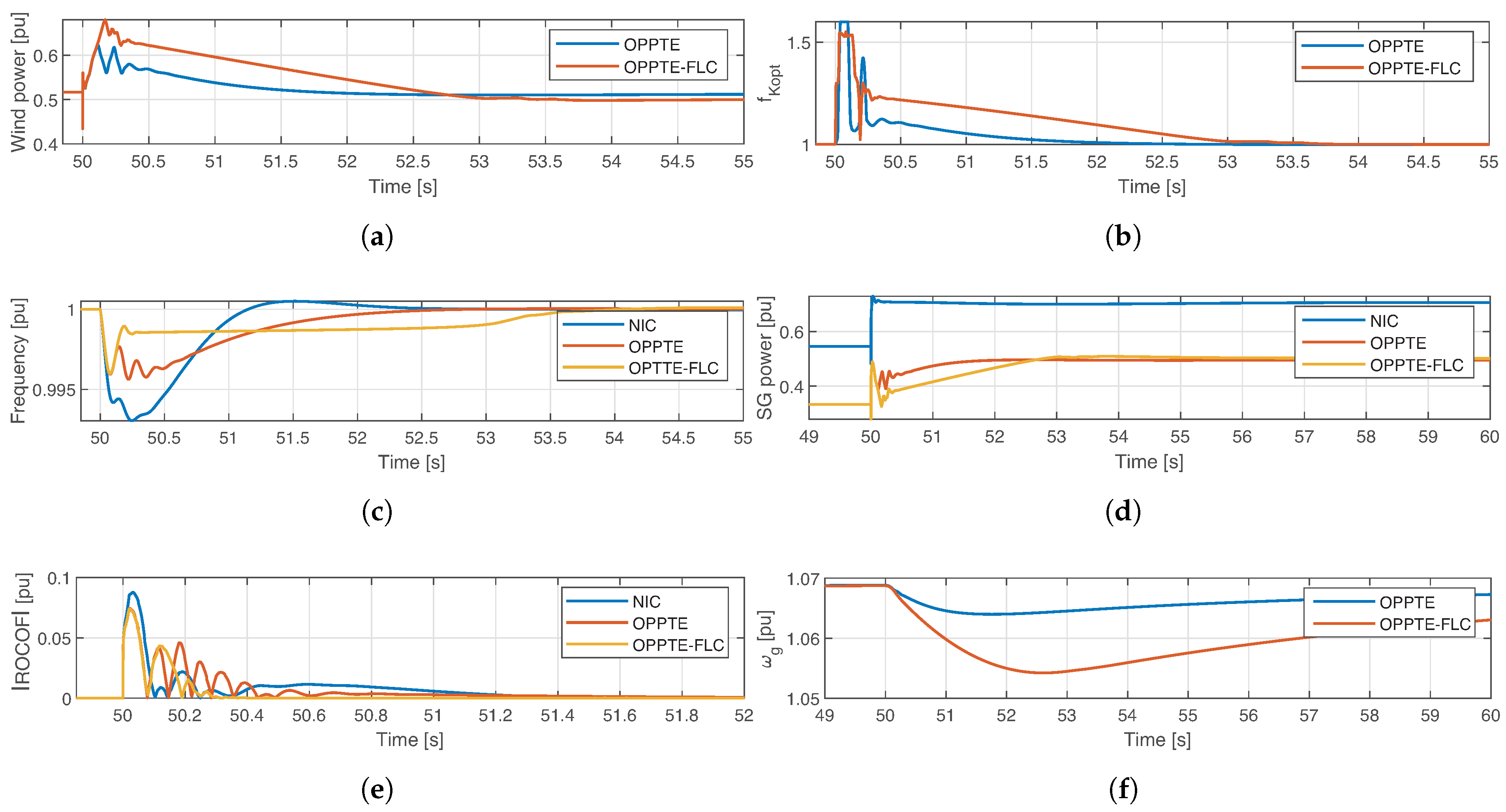
Figure 9 presents the key signals of the three simulated models at the moment of disturbance. Overall, the FLC-based inertial control method demonstrates a superior inertial response of the WECS when compared to both OPPTE and NIC. Specifically, the proposed controller achieves a 9.022% increase in instantaneous active power relative to OPPTE. In addition, the frequency nadir and ROCOF are reduced by approximately 8.23% and 5.11%, respectively, compared with the OPPTE method.
Figure 9a illustrates the active power injected into the grid by the WECS. It shows that, after the contingency event was detected at 50 s into the simulation, the OPPTE and OPPTEC-FLC inertial control schemes responded by automatically releasing the kinetic energy stored in the wind turbine’s rotating masses. Furthermore, it can be observed that the FLC-based inertial control maintained a higher active power level than that obtained using the OPPTE method for approximately 2 s.
Figure 9b illustrates the control variable
for the inertial control methods considered. For OPPTE, the control signal rapidly returns to its optimal value, whereas the proposed method produces a more gradual, linear decrease. This behavior enables the WECS to sustain a higher contribution of instantaneous active power during the disturbance.
Figure 9c presents the power system frequency dynamics. Following the contingency event, the NIC system reaches its lowest frequency nadir value, corresponding to 0.993 pu. In contrast, the OPPTE and OPPTE-FLC inertial control schemes improve this parameter, achieving values of 0.9956 pu and 0.9959 pu, respectively. It is worth noting that the settling times associated with the inertial controllers are longer compared to the NIC model, due to the greater participation of the synchronous generation unit. However, the NIC model exhibits an overshoot of 0.05%, an effect not observed in the inertial control systems. The active power of the synchronous generation unit is shown in
Figure 9d, where it is evident that both inertial control methods reduce the synchronous machine’s participation in frequency support. Notably, the FLC-based method yields a longer settling time for the synchronous unit, approximately 2.8 s.
Finally,
Figure 9e shows that the proposed FLC-based inertial control reduces the oscillations presented in the absolute value of the ROCOF compared to the OPPTE method. As a consequence of delivering additional active power, the rotor of the WECS experiences a slightly greater deceleration, as depicted in
Figure 9f. These results confirm that the proposed method provides more effective inertial support while maintaining overall system stability.
Table 4 summarizes the simulation results of the contingency event described previously, conducted at wind speeds ranging from 5 m/s to 10 m/s. The second column of
Table 4 shows the maximum value of the active power injected by the WECS, expressed in per-unit terms. The third column details the maximum frequency deviation from its nominal value, also in per unit. Finally, the last column reports the maximum absolute value of the ROCOF, expressed in per unit per second, for both inertial control systems. The results confirm that the proposed FLC-based inertial control consistently outperforms the OPPTE method across all operating conditions, particularly in terms of instantaneous active power, frequency nadir, and ROCOF. On average, the proposed controller increases the maximum instantaneous active power by 9.97%, while reducing the frequency nadir and ROCOF by 11.59% and 3.11%, respectively.
The contingency study with a 20% load increase and wind speeds ranging from 5 to 10 m/s (
Table 4) illustrates how the proposed OPPTE-FLC controller reshapes the inertial response compared with the original OPPTE method. For all wind speeds under consideration, the fuzzy-based controller delivers a higher maximum active power than OPPTE, with increases on the order of a few to several percentage points across the range (for example, from 0.4632 pu to 0.4975 pu at 8 m/s and from 0.6236 pu to 0.6799 pu at 9 m/s). At the same time, the maximum frequency deviation is consistently reduced, with the nadir moving closer to nominal frequency in every case (e.g., from
pu to
pu at 5 m/s and from
pu to
pu at 9 m/s). The indicators for the rate of change of frequency follow a similar trend: the peak
is slightly lower for the proposed controller across most wind speeds, with differences of a few percent, except at 10 m/s where both methods yield almost identical values. These results suggest that, for a wide operating range, the OPPTE-FLC scheme manages to inject more active power during the disturbance while keeping both the nadir and
at levels that are no worse, and often better, than those obtained with the reference method.
When these peak-based indicators are viewed together with the ITAE and ITSE indices reported elsewhere in the paper, a clear trade-off emerges between response speed and dynamic quality. The original OPPTE controller tends to reach its final operating point more quickly, which is reflected in lower ITAE values and shorter settling times, but at the expense of a more abrupt transient. In contrast, the OPPTE-FLC configuration shapes the active power injection so that the frequency excursion is less pronounced and is curtailed under most conditions, which improves the ITSE index and indicates a smoother response, even though the return to nominal frequency may take slightly longer. In practical terms, the controller proposed in this work does not seek to minimize a single performance index; instead, it rearranges the balance between speed and transient quality, favoring reduced nadir and moderated while accepting a modest increase in settling time. This compromise is maintained over the studied range of wind speeds, which suggests that the observed behavior is not confined to a single operating point but persists across different power levels of the wind energy conversion system, highlighting a trade-off between response speed and dynamic quality: as the kinetic energy stored in the turbine’s rotating masses increases with wind speed, the additional energy released during contingencies helps attenuate frequency excursions and ROCOF, at the cost of a slightly longer settling time.
Table 5 reports the results of constant wind speed (9 m/s) simulations under different grid-connected load increments. For the 4% and 30% contingency events, the proposed method yields a slightly higher frequency nadir compared with OPPTE. This behavior is attributed to the controller’s adaptive response, which prioritizes smoother and sustained active power delivery rather than an abrupt injection, thereby improving overall system stability. Nevertheless, the overall performance of the FLC-based inertial control is superior: it increases the maximum instantaneous active power by 6.56% and reduces the frequency nadir and ROCOF by 9.6% and 5%, respectively. These outcomes highlight the capability of the proposed approach to provide effective frequency support across a wide range of contingency severities.
4.2. Wind Speed Time Series Results
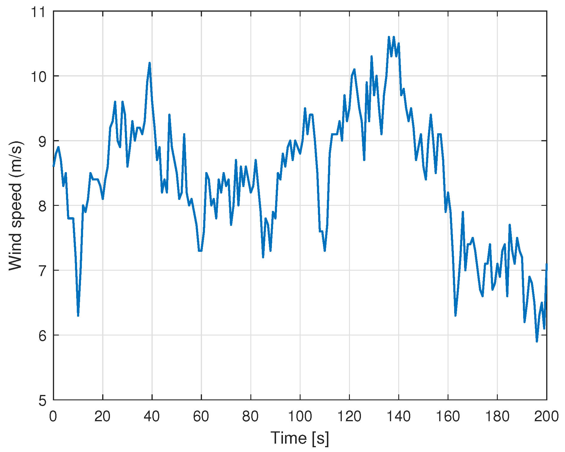
In this section, the performance of the OPPTE and FLC-based inertial control strategies is evaluated using a real-world wind dataset [
49]. The wind speed time series employed in this analysis is shown in
Figure 10.
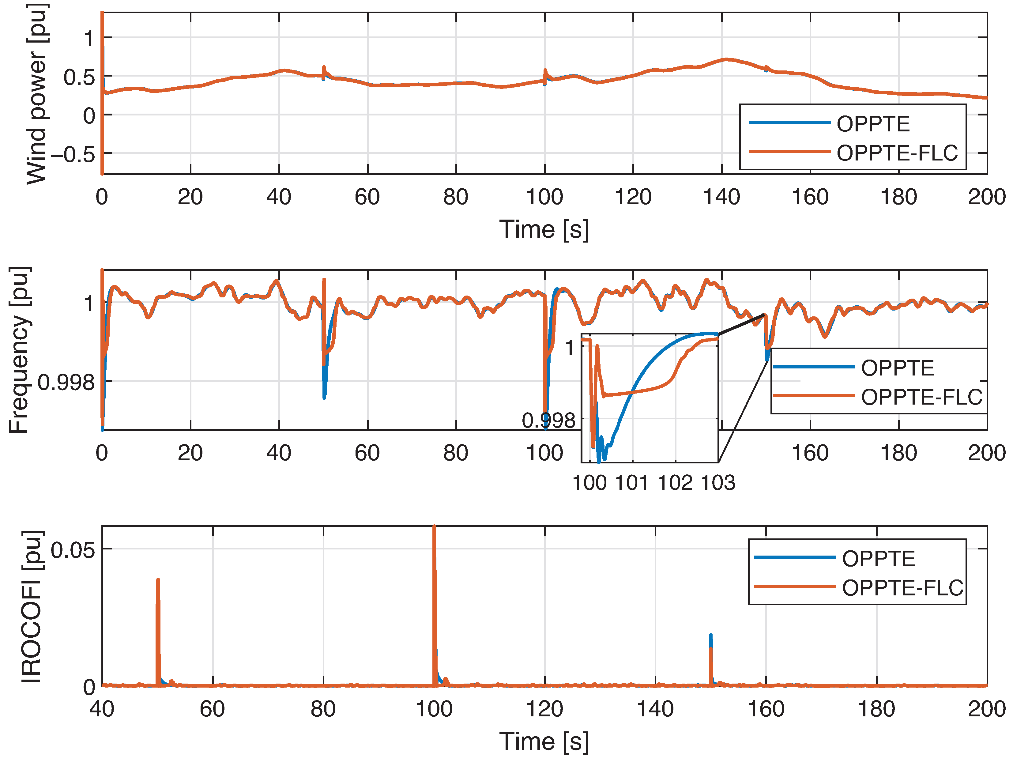
At t = 50 s, t = 100 s, and t = 150 s, contingency events are emulated by increasing the connected load by 10%, 15%, and 5%, respectively.
Figure 11 presents the dynamic response of the power system under a wind speed series scenario. The upper graph in
Figure 11 shows the wind power generated as a function of the wind speed time series. Generation peaks associated with the inertial control schemes, which exhibit similar dynamic behavior, are identified at 50, 100, and 150 s. The central graph illustrates the evolution of power system frequency, demonstrating that the OPPTE-FLC method achieves a more pronounced reduction in the frequency nadir compared to the OPPTE method. Finally, the lower graph represents the absolute ROCOF value, whose response shows a similar trend among the different inertial control systems evaluated. Across the entire wind speed time series, both inertial controllers (OPPTE and the proposed FLC-based method) maintain the system frequency close to its nominal value. However, notable differences appear during the contingency events: the proposed FLC-based inertial control achieves higher instantaneous active power, a reduced frequency nadir, and improved ROCOF compared to OPPTE.
Quantitatively, the FLC-based method increases the instantaneous active power by an average of 9.677%, while reducing the frequency nadir and ROCOF by 6.4% and 4.57%, respectively. These improvements are particularly evident in the zoomed view of the third contingency event in the frequency response plot, where the superiority of the proposed method becomes more pronounced.
5. Discussion
By analyzing the maximum instantaneous active power, frequency nadir, and ROCOF, the proposed FLC-based inertial control demonstrates superior inertial response compared to both OPPTE and NIC. In addition to these metrics, this section evaluates the performance of the inertial control systems using two time-weighted error indices: the Integral of Time Absolute Error (ITAE) and the Integral of Time Squared Error (ITSE). Their mathematical formulations are given by:
where e(t) represents the frequency deviation at time t.
Table 6 summarizes the ITAE and ITSE indices obtained from simulations under constant wind speed with load changes. The FLC-based inertial control achieves a 36.67% reduction in ITSE compared to OPPTE, reflecting its ability to deliver a smoother dynamic response with lower error energy over time. Conversely, the ITAE index increases by 13.36% relative to OPPTE. This result arises because the proposed controller requires approximately 1 s longer to reach steady state. However, this slower settling time contributes to a less abrupt and more gradual inertial response, which explains the superior ITSE performance.
Overall, these findings indicate that the proposed FLC-based method achieves a favorable trade-off: although the ITAE is slightly higher, the significant improvement in ITSE demonstrates enhanced stability and robustness of the inertial response when compared to conventional OPPTE control.
The dynamic behavior reported in
Table 6 is consistent with the outcomes of the performance indices (ITAE and ITSE) obtained from simulations using a wind speed time series with varying load fluctuations. Compared with OPPTE, the FLC-based inertial control increases ITAE by 13.43% while reducing ITSE by 4.69%.
Overall, the proposed OPPTE-FLC inertial control method exhibits an improved inertial response, achieving higher instantaneous active power and reducing both the frequency nadir and the absolute value of ROCOF relative to OPPTE. Furthermore, the method presented in this article demonstrates better ITSE performance, confirming its ability to smooth the system’s dynamic response. In contrast, the controller does not improve the OPPTE response with respect to the ITAE index. This behavior is attributed to the linear reduction of the control signal
in the OPPTE-FLC response, as illustrated in
Figure 9b, which results in a slightly longer settling time but contributes to a more gradual and stable inertial contribution.
The incorporation of inertial control schemes reduces the required size of energy storage systems (ESS) intended to support frequency regulation. Several studies, such as [
50,
51], highlight the use of supercapacitors in FFR applications, given their high power density, adequate energy density, and response times on the order of seconds, making them particularly suitable for complementing inertial support.
This manuscript does not include explicit simulations of ESS as auxiliaries in frequency regulation. For this reason, the results reported in [
52] are adopted as a reference, which concludes that a supercapacitor-based ESS should be sized with a nominal power equivalent to 10% of the installed wind power. This criterion allows establishing a baseline value for a simplified comparative analysis with the inertial control method proposed in this work. Thus, for the power system considered, the nominal power required for a supercapacitor-based ESS amounts to 240 kW. Based on the results presented in
Section 4.2, and focusing on the power variation of the wind turbine during the first contingency event (
= 10%), it is found that the WECS contributes:
Under operating conditions with variable wind speed and a 10% increase in load, the OPPTE-FLC inertial control system achieves a 46.3% reduction in the nominal power required by a supercapacitor-based ESS.
6. Conclusions
6.1. Summary of Main Findings
This article investigated an FLC-based inertial control method to enhance the inertial response of a WECS. The proposed strategy builds upon the OPPTE methodology, which adjusts the turbine operating point in response to contingency events. By enabling wind turbines to contribute to frequency support, this approach reduces the reliance on additional energy storage systems for fulfilling ancillary service requirements.
The design of the fuzzy controller was a critical stage, particularly in the selection of input signals and their associated membership functions. While triangular membership functions are commonly adopted in the literature, this work employed Gaussian functions, which yielded superior results due to their smooth and continuous profiles. To the best of the authors’ knowledge, no prior research has reported the integration of a fuzzy controller with the OPPTE framework using both frequency deviation and its time derivative as input signals.
Simulation results demonstrated that the proposed FLC-based inertial control method increases the maximum instantaneous active power and reduces both the frequency nadir and ROCOF of an isolated power system when compared to the OPPTE controller. Analysis of the ITAE and ITSE performance indices further confirmed this behavior: the proposed method achieves a better ITSE index, reflecting a smoother inertial response, whereas OPPTE achieves a better ITAE index due to its faster settling time.
Finally, these findings indicate that the inertial response of WECS can be significantly improved through the proposed FLC-based strategy, providing effective frequency support and strengthening system stability in grids with high wind power penetration.
6.2. Limitations and Future Work
This paper is limited to a comparative analysis within the context of the OPPTE method, based exclusively on the application of a fuzzy logic controller. However, a natural extension of this study, and an opportunity to strengthen its contribution to the state of the art, lies in exploring the integration of advanced control techniques—such as neural networks or predictive models—aimed at improving the inertial response of the OPPTE method.
The addition of a fuzzy logic controller (FLC) to the OPPTE method introduces greater complexity compared to the conventional OPPTE scheme, due to the increased number of parameters to be adjusted, the inference process, and the need to properly define the membership functions. This increased complexity can lead to a slight increase in computational latency, especially when using numerous fuzzy sets or when the control platform has limited resources. However, in modern systems based on digital signal processors (DSPs) or field-programmable gate arrays (FPGAs), this delay is practically negligible compared to the benefits gained in terms of flexibility and adaptability to varying operating conditions. Furthermore, in frequency control applications, frequency deviation and rate of change of frequency (ROCOF) measurements require high accuracy, which implies greater filtering and processing requirements for the input signals. Nevertheless, the fuzzy nature of the controller enables a more robust response to the system’s uncertainties and nonlinearities, constituting an effective alternative to the conventional OPPTE inertial control method. This practical observation of the method proposed in this article opens the possibility of moving towards future work that considers its implementation in a real application within a microgrid as a first approach.
The present study does not include a systematic assessment of sensitivity to measurement errors or turbine parameter dispersion, since the experimental platform available to the authors is a laboratory microgrid with converter-interfaced units in the range of a few tens of kilowatts, whose inertia and short-circuit levels differ substantially from those of the medium-voltage system modeled in this work. In addition, the authors do not have access to an extensive catalog of commercial wind turbine models in simulation tools, which would be necessary to represent parameter dispersion and measurement uncertainty across different units in a consistent manner. Under these conditions, reproducing the same frequency excursions and rates of change would require strong scaling assumptions that fall outside the scope of the paper. Moreover, the present analysis does not capture the influence of turbulent wind conditions and realistic noise in frequency measurements, which can affect controller tuning and observed performance. This limitation is acknowledged in the conclusions and will be addressed in future work through hardware-in-the-loop tests or dedicated experimental setups with controlled noise, parameter variations, and representative wind profiles.
Finally, the scalability of the proposed method is feasible due to the modular structure of the OPPTE-FLC controller. To achieve this scalability, a viable strategy is to implement distributed or hierarchical control schemes, in which each wind turbine operates with a local fuzzy controller. At the same time, a higher layer handles global coordination, ensuring adequate inertial and frequency support participation for all devices. Furthermore, incorporating communication and information aggregation mechanisms—for example, through a supervisory controller or a plant manager—would enable the dynamic adjustment of the references and weights assigned to each unit, thereby preventing control conflicts and maintaining system stability. Thus, the fuzzy approach developed in this work can be naturally extended to scenarios with multiple wind turbines, providing a solid foundation for future research focused on cooperative control in wind farms.
