Review

A Review of Fused Filament Fabrication of Metal Parts (Metal FFF): Current Developments and Future Challenges

1
Commonwealth Scientific and Industrial Research Organisation (CSIRO), Manufacturing Research Unit—Research Way, Melbourne, VIC 3168, Australia
2
Department of Sciences and Methods for Engineering (DISMI), University of Modena and Reggio Emilia—Via Amendola 2, 42122 Reggio Emilia, Italy
*
Author to whom correspondence should be addressed.
Technologies 2024, 12(12), 267; https://doi.org/10.3390/technologies12120267
Submission received: 26 November 2024 / Revised: 13 December 2024 / Accepted: 17 December 2024 / Published: 19 December 2024
(This article belongs to the Section Innovations in Materials Processing)

Abstract

:
Fused filament fabrication (FFF) is the most widespread and versatile material extrusion (MEX) technique. Although powder-based systems have dominated the metal 3D printing landscape in the past, FFF’s popularity for producing metal parts (“metal FFF”) is growing. Metal FFF starts from a polymer–metal composite feedstock and proceeds through three primary stages, namely shaping (i.e., printing), debinding, and sintering. As critically discussed in the present review, the final quality of metal FFF parts is influenced by the characteristics of the composite feedstock, such as the metal loading, polymer backbone, and presence of additives, as well as by the processing conditions. The literature shows that a diverse array of metals, including steel, copper, titanium, aluminium, nickel, and their alloys, can be successfully used in metal FFF. However, the formulation of appropriate polymer binders represents a hurdle to the adoption of new material systems. Meanwhile, intricate geometries are difficult to fabricate due to FFF-related surface roughness and sintering-induced shrinkage. Nonetheless, the comparison of metal FFF with other common metal AM techniques conducted herein suggests that metal FFF represents a convenient option, especially for prototyping and small-scale production. Whilst providing insights into the functioning mechanisms of metal FFF, the present review offers valuable recommendations, facilitating the broader uptake of metal FFF across various industries.

Graphical Abstract

1. Introduction

Additive manufacturing (AM), which originated in the 1980s, has transitioned from being primarily used for the quick production of models or prototypes to the fabrication of real engineering components for critical applications in industries such as aerospace, automotive, and biotech [1]. This progress has encouraged the evolution of AM technologies to accommodate a wide range of materials, including polymers, ceramics, metals, and composites [2]. Metals, in particular, have attracted significant attention both in research and in industrial settings due to their unique properties, such as a high strength-to-weight ratio, functional properties such as electrical and thermal conductivity, and design flexibility for different AM techniques [2,3]. For complex metal parts, which are typically encountered in advanced applications, AM can overcome the geometric limitations of manufacturing methods like casting, forging, and machining. This means it can be a more cost-effective and time-efficient alternative, particularly for difficult-to-process materials such as titanium (Ti), nickel (Ni) superalloys, and refractory metals [4]. Such metals and alloys have been extensively adopted in the aerospace and automotive industries owing to their remarkable mechanical properties and superior corrosion resistance at high temperatures compared to aluminium (Al) alloys or steel [1,5]. AM enables the production of metallic parts with intricate geometries, reduced material waste, and faster design iteration cycles, thereby resulting in shorter lead times and increased flexibility for manufacturers [6]. It is estimated that metal AM is poised to achieve an annual growth rate of over 29% from 2021 to 2025 [7].
Metal AM encompasses a variety of technologies, each presenting unique advantages and limitations. Powder bed fusion (PBF) methods, such as selective laser melting (SLM, i.e., laser-based PBF) and electron beam melting (EBM, i.e., electron beam-based PBF), represent the predominant segment in the metal AM market due to their technological maturity. PBF systems involve the melting or sintering of powders uniformly distributed layer by layer within a designated workspace [8,9]. These systems offer the potential to achieve high-density parts of up to 99.9% of nominal density, with high-resolution features [10]. They also enable the fabrication of intricate components for critical applications, exhibiting exceptional physical and mechanical properties [6]. In contrast, in direct(ed) energy deposition (DED) systems, such as laser metal deposition (LMD), an energy source, such as a laser, electron beam, or plasma arc, is used to melt the metal powder or wire as it is being deposited. This approach accommodates larger build volumes than PBF and offers great versatility for the repair of worn or damaged metal components [1]. Wire arc additive manufacturing (WAAM) is a type of DED technology that uses an electric arc as the heat source and a metal wire as the feedstock. The heat source melts the metal wire upon contact, depositing it onto the workpiece where it solidifies. WAAM offers several advantages that include high deposition rates, efficient material usage, and the ability to produce large parts. As a result, WAAM is suitable for aerospace, maritime, and other heavy industry sectors [11]. Powder fed fusion (PFF) is a subset of DED in which metal powders are fed through a nozzle directly into the melt pool, where a laser sinters them onto the build surface [12]. Another popular method for metal AM is binder jetting (BJ), which builds solid objects by selectively depositing a liquid binding agent onto a bed of powder material, layer by layer. Once printing is complete, the part may undergo post-processing steps such as curing, infiltration, or sintering, depending on the material and application. BJ is suitable for producing large, low-cost metal parts [13], and is highly amenable to embedding functional features [14].
Although these AM technologies enable geometric freedom to produce metallic parts, they have several important limitations including a large capital cost, substantial energy consumption during operation [15], and the need for demanding safety measures, especially in powder-based AM processes [16]. Moreover, most raw metals of interest, like Ti, are extremely expensive, and the cost-related issues are exacerbated when such metals are to be transformed into high-quality powders for 3D printing by gas or plasma atomization techniques. This contributes to the already high operational costs of metal AM [17]. It is also worth noting that the repetition of rapid heating and cooling cycles that underpins the layer-wise build-up mechanisms in PBF and DED, besides being energy consuming, has a profound influence on the microstructure along the build direction and, consequently, on the mechanical properties of the finished components [18].
To address these challenges, researchers and manufacturing industries have been developing new AM processes to produce metallic components more affordably and in a more environmentally friendly and sustainable way. This has led to the adoption of material extrusion (MEX) for fabricating 3D-printed metal parts [19]. MEX, as defined according to ISO/ASTM 52900:2021 [20], is an AM process that involves the deposition of a material flowing through a nozzle onto a substrate in a controlled manner. In the context of this paper, it is essential to note that MEX is a very broad category encompassing various technologies that utilise diverse types of feedstocks, including semi-liquid, semi-solid, and solid materials. Accordingly, the feeding system in MEX printers can vary, with options such as syringe-based, plunger-based, or filament-based mechanisms [21]. This paper specifically discusses metal-MEX starting from a filament, which means that the first stage (“printing” or “shaping”) of the workflow that leads to the production of metal parts is conducted through a technique normally called “fused filament fabrication” (FFF) or “fused deposition modelling” (FDM). Historically, different names have been introduced by different research groups to identify this technology [22,23]. For a matter of clarity, herein we use the term “metal FFF”.
Metal FFF offers several advantages over powder- or wire-based metal AM processes that require high-energy sources, since FFF uses relatively low temperatures to fuse a binder material (often a thermoplastic polymer) and the interlayer bonding is driven by the diffusion of polymer chains [24]. Nonetheless, as is often seen in metal-based BJ, metal FFF requires a high-temperature sintering step after printing. Although FFF has been extensively employed for fabricating plastic components, its use for metals has been somewhat limited, primarily due to the initial perception of FFF technology as a hobbyist-level technology, mainly appreciated for the rapid prototyping of plastic components and spare parts. However, the outstanding flexibility of FFF in terms of feedstock materials has provided the opportunity to print metal-based filaments for making fully inorganic parts [21]. To this end, the filament must be made of a composite material comprising a polymer-based binder and the metal or alloy of choice. After printing, all traces of the polymeric binder must be removed, leaving behind a fully inorganic part that is ultimately consolidated via thermal sintering.
Metal FFF is safer than PBF methods for both the operator and the environment since the metallic powder is encapsulated within a polymer matrix [16]. Additionally, when the production volume is relatively low, metal FFF becomes a competitive solution compared to PBF methods, primarily due to its lower investment cost [25,26]. Many desktop FFF printers can be inexpensively acquired, typically costing less than US$10,000. Even hobbyist FFF printers for polymer parts, which are far less expensive than industrial machines, can be easily and economically upgraded to print metal-based parts [27]. Dual extrusion printheads further broaden the capabilities of metal FFF, because they allow different feedstocks and specialty support materials to be incorporated in the same object [28].
With recent advancements in materials and in process control, FFF is gaining traction for the AM of metallic components [29]. Accordingly, FFF has already been applied to produce 3D-printed parts comprising materials such as stainless steel (SS), Ti, Al, and Ni superalloys. The use of metal FFF has been suggested to reduce manufacturing costs for complex geometries compared to conventional manufacturing methods, such as investment casting and forging. Metal FFF is cost-competitive because it eliminates the need for expensive machining and limits the volume of waste material, particularly for high-performance alloys such as Ni-based superalloy Inconel (IN) 718 [30]. Moreover, when production volumes are low, such as with custom impellers and nozzles, parts can be affordably prototyped and produced using metal FFF. An example of this is metal FFF using Ti-6Al-4V, which was investigated for manufacturing a centrifugal compressor. The Ti-6Al-4V filament demonstrated the ability to produce prints of high quality with good geometric accuracy [31]. As another example, in the biomedical industry, metal FFF has been assessed to 3D print patient-specific maxillofacial implant prototypes. These prototypes exhibit superior osteointegration and biocompatibility compared to fully dense implants produced using traditional manufacturing methods like investment casting. This enhancement is attributed to the interconnected open porosity present within the FFF components, a feature that can be fine-tuned during the feedstock preparation and printing processes. This porosity closely resembles the characteristics of bone, offers attachment points for bone tissue, and facilitates osseointegration. Additionally, it contributes to a more uniform stress distribution between the implant and the adjacent bone [32].
In spite of its increasing success, metal FFF is still in the early stages of development. Meanwhile, multiple factors, such as filament quality, printing parameters, and post-processing treatments, can influence the properties of the final product. Additionally, further improvement in the 3D printing process and associated software may be needed to facilitate the industrial uptake of metal FFF. Particular attention should be paid to enhancing the inter-layer adhesion. This may involve strategies such as preheating the preceding layer immediately prior to the deposition of the subsequent layer [33]. Recent studies have shown that achieving adequate adhesion between layers during printing is crucial for improving the mechanical properties of the final (sintered) specimens. For example, SS parts produced through metal FFF exhibit good mechanical properties provided they achieve strong interlayer bonding [34].
Research is still necessary to gain a deeper understanding of the potential and limitations of metal FFF, and to explore new and innovative applications for this technology. Currently, only a few companies such as Markforged and Desktop Metal commercialise printing equipment and filaments for metal FFF [29,35,36]. Although still rare in the marketplace, these commercial systems have proved to be successful in a broad range of industrial settings. For example, the metal FFF of stainless steel is routinely used to produce grippers and end-of-arm tools (namely, the articulated extremities of robotic arms), lightweight brackets and supports, high-wear tooling, custom fixtures and fittings (such as one-off wrenches and sockets), moulds and extrusion dies, and functional prototypes. In the automotive sector, producing low-volume parts or components that are no longer being produced for legacy cars has become easier and more affordable than it was with conventional fabrication methods. Metal FFF is also penetrating the leisure industry segment, with featured applications as diverse as design jewellery, stylish chess pieces, and personalised components of music instruments. On account of its electric and thermal conductivity, copper is preferred for the fabrication of induction coils, bus bars, welding shanks, electron discharge machining (EDM) electrodes, and heatsinks. Nickel-based alloys are the ideal feedstock for high-temperature and corrosion-resistant components and spare parts, for crucibles, and for turbine hardware. Metal FFF also has tremendous potential in the biomedical field, for the development of surgical tools and patient-specific implants. However, as further discussed in the following sections, further research is needed to make titanium and titanium alloy filaments commercially available.
Some fundamental advantages of these commercial metal FFF platforms are their reliability, cost effectiveness, and simplicity of use. However, these commercial systems are typically ‘closed’, meaning that they require proprietary feedstocks, which should be selected from a limited catalogue of materials such as tool steel or copper. Furthermore, often the details of both the feedstock formulation and the 3D printing process are not disclosed. This lack of information means that it is extremely challenging for a user to comprehend the relationship between material formulation, metal FFF, and the corresponding mechanical performance of the fully inorganic part following the sintering stage. On the other hand, after some key patents regarding FFF have expired, open-source printers have allowed researchers and scientists to experiment with new materials and printing parameters. Given the potential of metal FFF and the need for a deeper understanding of its capabilities and limitations, this review aims to provide an overview of the metal FFF technology, its current state, and its potential applications.
After introducing the functioning mechanisms of MEX and metal FFF in Section 2, we analyse the role of the composite feedstock in Section 3 and discuss the main processing steps (printing/shaping, debinding, and sintering) in Section 4. Section 5 analyses the materials portfolio currently being employed in metal FFF. Then, in Section 6, we explore emerging trends in the scientific literature and identify the technological gaps that may limit this technology’s progression. Various factors that affect the quality of FFF-printed metal parts are discussed, along with potential solutions that may be pursued to overcome existing challenges. Finally, the pros and cons of metal FFF as compared to PBF are thoroughly analysed in Section 7, thus making available both the background knowledge and practical guidelines for practitioners and newcomers in the field of metal AM. It is hoped that the insights provided in this paper can contribute to the advancement of metal FFF and facilitate its adoption more broadly across a wide range of industries.

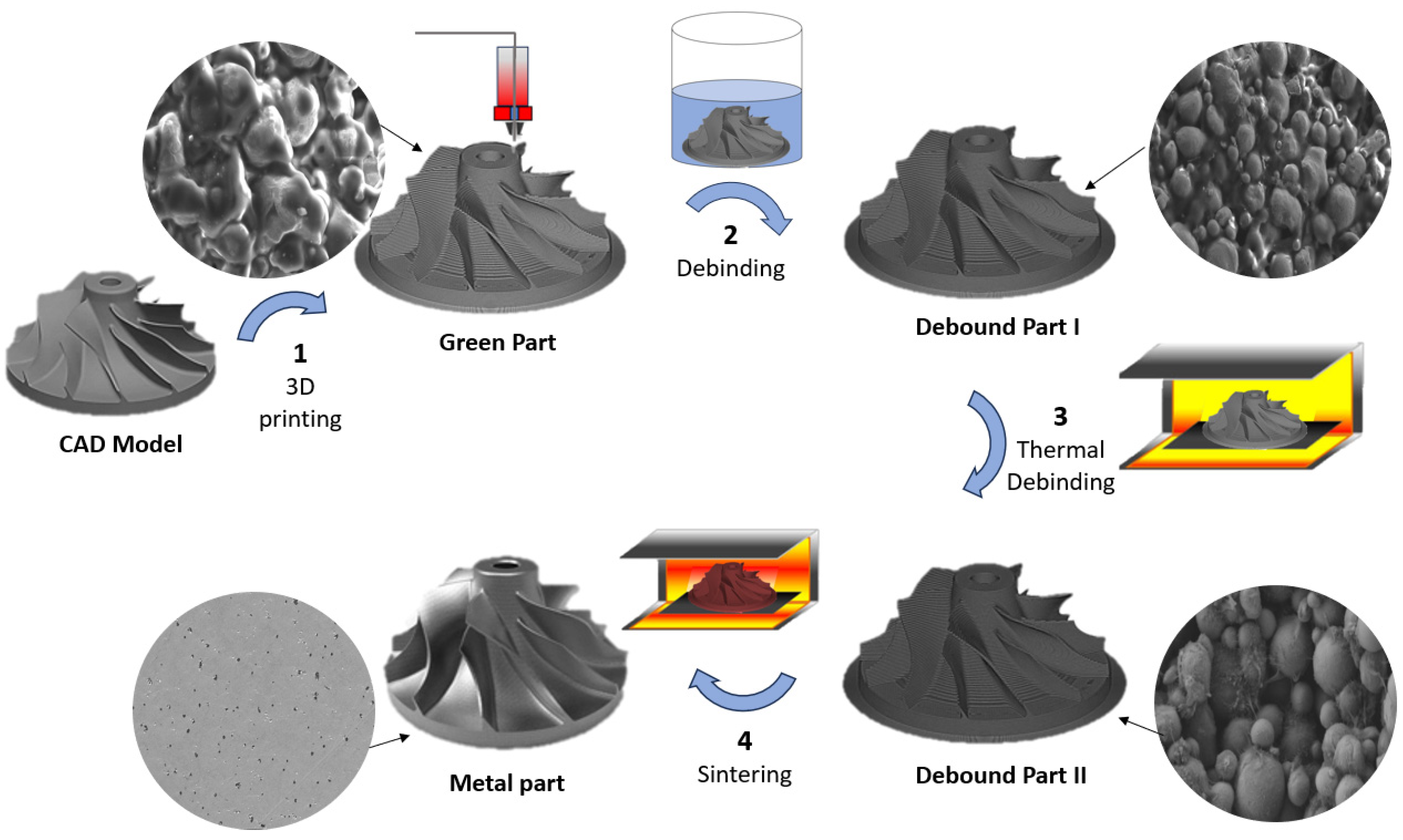
2. Making Metal Parts by FFF: Basic Principles of Metal FFF

As previously mentioned, the build-up strategy underpinning MEX is, in principle, relatively straightforward, as 3D parts are obtained through the deposition of extruded matter. MEX has evolved significantly over the past few years with advancements in materials, printing technology, and software. MEX machines can now achieve high print resolution with layer heights in the order of 0.05 mm (or even lower, with some techniques like direct ink writing) and build volumes that are several times larger than the first MEX machines. It is also possible to print with a variety of materials, including thermoplastics, composites, metals, and ceramics [8,37,38].
Metal MEX shares many similarities with metal injection moulding (MIM), a manufacturing process that combines the principles of plastic injection moulding and powder metallurgy. MIM involves mixing fine metal powders with a polymer-based binder to produce a feedstock, which is then melted and injected into a mould cavity under high pressure. The moulded part is subsequently debound and sintered to produce a solid metal component with relatively complex shapes and high dimensional accuracy [19,39]. In metal MEX the multi-component feedstock (similarly combining a polymer matrix and a metallic powder) is processed by means of a multistage process, which includes the shaping, debinding and sintering (SDS) steps, where “shaping” is accomplished by 3D printing [21,40]. To this end, the metal powder is mixed with a polymer binder and compounded into a feedstock that can take on a variety of forms such as slurries, colloids, granules, bars, or filaments, depending on the type of printer [41]. The feedstock is then used to print a binder–metal composite part—also known as the “green part”. Subsequently, the green part undergoes debinding and sintering in a controlled atmosphere (for instance, hydrogen, nitrogen, and argon gases or vacuum), which is required to consolidate the metal powder and increase the part’s density [42].
Like any other AM technique, printing an object for metal MEX begins with a 3D model, created using Computer-Aided Design (CAD) software or via 3D scanning. The 3D model is typically in the form of an “STL” file, which is sliced and converted into “g-code” using slicing software. The g-code is then loaded to the printer. Depending on the feeding system used by the printer, the metal MEX process can be categorised broadly into three types, namely filament-based (i.e., metal FFF), screw-based, and plunger-based [19], as shown schematically in Figure 1.
The peculiarity of FFF-based processes (including the printing step in metal FFF) is that they employ a polymer-based filament that is fed by a transport system to the melting zone near the heated nozzle, which oversees the extrusion process [43,44,45]. As illustrated in Figure 2, the transport system consists of driving rollers or gears that pull the spooled filament into the melting zone and push the softened material out through the nozzle. While extruding the polymer melt, the printhead follows the predefined path in the XY-plane, moving on a gantry via stepper motors. Each layer of the printed part is built up by the progressive addition of neighbouring “strands” or “rasters” of material. Once the first layer is complete, the build plate moves down, or the gantry moves up, by one layer in height, and the process repeats based on the g-code instructions, printing the 3D object layer by layer. In principle, any FFF printer, even desktop ones, can be used for metal FFF. However, the high-volume fraction of metal in the filament results in a high wear rate of the printing nozzle; therefore, a specially hardened or wear-resistant nozzle should be used to maintain a stable flow of the filament over time and increase the life of the nozzle [44].
Screw-based MEX printers involve the use of a rotating screw to transport the granulated feedstock to the nozzle. Screw-based systems provide the most versatility concerning the composition of the feedstock material. This is because they can employ granules, thereby bypassing the need for specific filament properties. Besides this, screw-based systems offer two main advantages. First, the feedstock can be continuously fed without interruption, resulting in increased productivity by reducing the overall printing time without the need for process stoppages during feedstock reloading or reheating. Second, the use of pellets as raw feedstock allows for higher filler loadings which in turn improve the final part density [45,46]. However, screw-based printheads are typically bulkier and heavier than filament-based ones, which may impair the printing accuracy due to inertial forces, especially for large-scale objects. This may also lead to decreased printing speed.
Plunger-based systems receive cylinder-like feedstock that is inserted into a cartridge surrounded by a heated sleeve and fed into a plasticizing unit that pre-heats and softens the material. The softened material is then accumulated in a barrel, and a plunger drives it into the melting zone. These systems are able to process composite materials with a high filler loading, comparable to MIM feedstock. However, an additional step is required to transform the raw, highly filled feedstock into a cylinder of the right size to fit the cartridge. Another limitation of plunger-based systems is the process discontinuity related to the cartridge refill. This results in a longer printing time and a deterioration of the printed part’s quality [45,47].
Screw and plunger-based systems can also be used for printing slurries and pastes that exhibit a viscous consistency [21,48]. However, printing slurries and pastes poses significant challenges due to their inferior dimensional stability compared to solid feedstock [49,50]. Furthermore, slurries and pastes predominantly employ organic solvents as a carrier. Additional complexity arises, therefore, from the removal of the organic solvent after printing.
Recently, commercial machines such as the Desktop Metal system have emerged, capable of printing using bars or rods infused with metal powders [51]. While these systems offer a practical alternative to other metal-MEX systems, commercially available materials only include a limited number of options, such as 17-4 PH, 316L SS, H13 tool steel, 4140 low-alloy steel, and copper rods [52].
Ultimately, FFF is the most popular MEX technique for producing metal parts, due to its ease of use and safety in handling the filament-like feedstock. In the future, the adoption of metal FFF is expected to grow further thanks to the increasing availability of commercially produced metal filaments [53,54].
The most intuitive way of making metal parts by FFF involves treating the metal (or alloy) in a similar manner to a polymer, namely feeding, melting, and printing a metal filament. This approach has been demonstrated with low-melting-point alloys (LMPAs), especially tin-based and bismuth-based alloys, which have melting temperatures similar to those of thermoplastic materials and can be processed like a normal filament for FFF. For example, Mireles et al. [55] investigated the use of six commercially available LMPAs for soldering (Bi36Pb32Sn31Ag1, Bi58Sn42, Sn63Pb37, Sn50Pb50, Sn60Bi40, Sn96.5Ag3.5). This work verified the feasibility of 3D printing LMPAs by FFF for the rapid production of conductive components and metal spare parts for space applications. Warrier and Kate [56] compared a low-melting-point eutectic alloy of bismuth (58% Bi, 42% Sn), a non-eutectic alloy of bismuth (40% Bi, 60% Sn), and a non-eutectic alloy of antimony (7.5% Sb, 89% Sn) for FFF. Interestingly, the non-eutectic alloys were found to have issues and clog the nozzle while printing, mainly due to the residual existence of solid phases during printing.
Ultimately, the absence of a polymer binder (as required, instead, in SDS) simplifies the part’s production, as it eliminates the debinding and sintering steps. However, although conceptually simple, printing metal filaments by FFF is actually very challenging [57]. When dealing with LMPAs, one of the main hurdles arises from the rheological behaviour of the melt [55]. Most LMPAs have very low viscosity when melted, and do not show shear-thinning behaviour. Shear thinning, also known as pseudoplastic behaviour, which refers to a non-Newtonian fluid property where the viscosity decreases as the shear rate (applied force or stress) increases [58,59]. Shear thinning is fundamental in FFF, as the molten material can easily flow through the print nozzle (high shear rates leading to low viscosity) and then promptly fix the targeted geometry once deposited on the build platform or the previous layers (low shear rates leading to high viscosity) [60].
Further to this, the direct printing of metal filaments is undoable for high-melting-point materials, such as Ti and Ni, and the SDS process ultimately becomes strictly necessary [42]. Figure 3 illustrates the steps involved in metal FFF through SDS, from printing the green part to the achievement of the final metal part after sintering. These steps will be discussed critically in Section 4. However, before diving into the details of the process, Section 3 will introduce the main properties of the composite feedstock to be used in metal FFF, which must be a filament comprising fine metal particles dispersed in a sacrificial binder.

3. Polymer–Metal Composite Feedstock for Metal FFF

One critical aspect in metal FFF through SDS is the formulation of a well-adjusted metal–polymer composite feedstock, which requires a delicate balance between several factors, including printability and sinterability [61,62,63]. Also, it must be possible to safely remove the binder without affecting the part’s geometry and integrity.
Understandably, the “printability” of the feedstock material represents a pre-requirement of pivotal importance. As outlined by Duty et al. [64] and by Das et al. [65], a feedstock material for FFF should satisfy a number of requirements, including the following:
  • Rheological behaviour: The feedstock material should exhibit appropriate rheological properties that enable its flow through the printer nozzle during the printing process. These properties account for appropriate viscosity, and shear stress- and temperature-dependent flow behaviour.
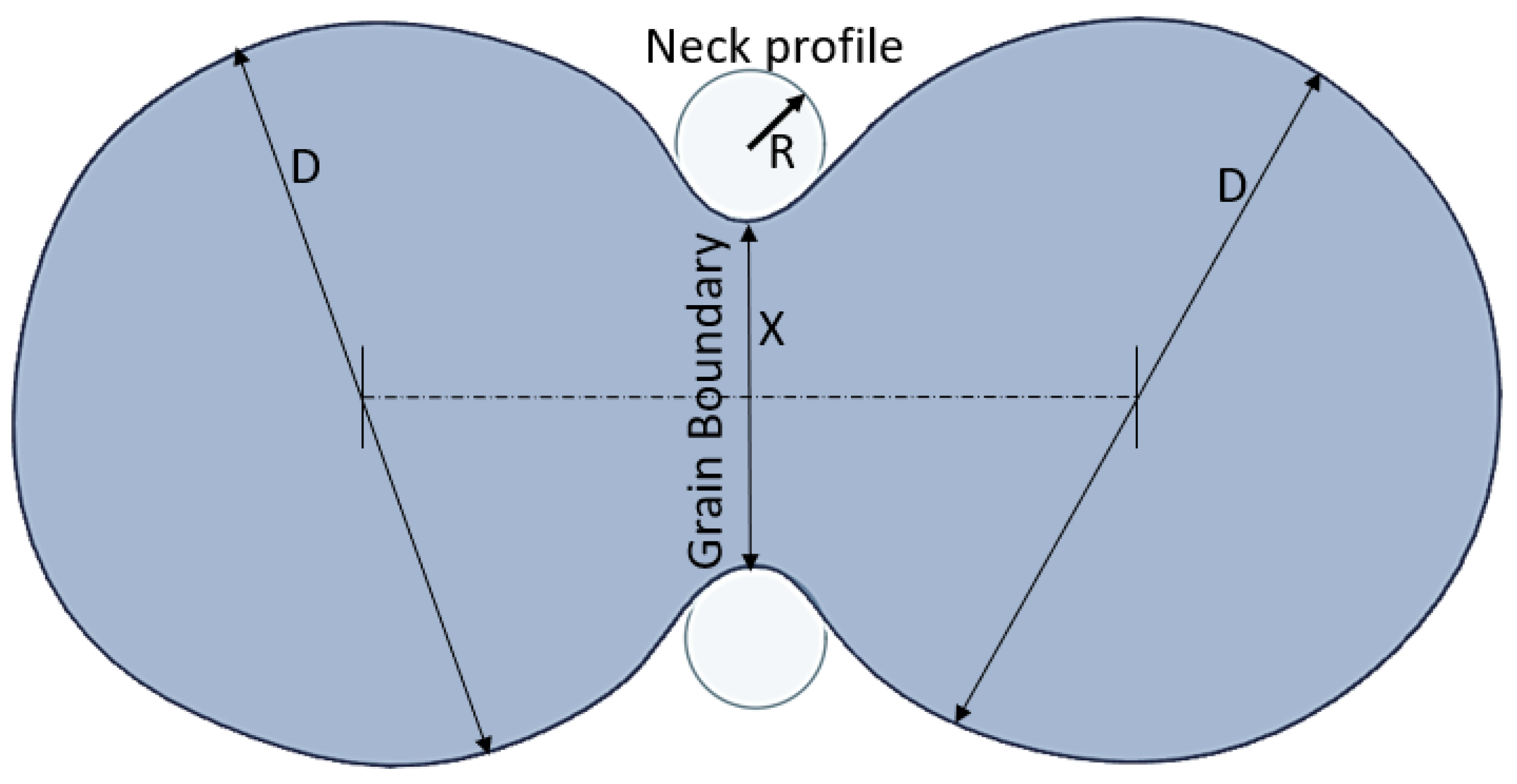
  • Solidification and bonding characteristics: Following extrusion from the nozzle, the material must be able to quickly solidify and establish a strong bond with the preceding layer. This depends on the material’s cooling rate, adhesion characteristics (meaning the ability of the freshly deposited raster to bond and fuse with previous rasters and layers through necking and polymer-sintering processes), and phase transition behaviour.
  • Bridging ability: The material must be able to “bridge” a gap of a given length corresponding to the inter-raster distance for parts printed with a sparse infill degree.
  • Stability under reheating: During the printing process, previously deposited layers are reheated as new layers are added. The material, therefore, needs to retain its form and structural integrity upon reheating, without warping, shrinking, or otherwise deforming.
In metal FFF, targeting these requirements greatly depends on the polymer binder formulation. The binder mix must meet mechanical properties essential for optimal filament performance, including the flexibility to facilitate smooth spooling, the stiffness and strength for effective printing (with the filament acting as a plunger at the entrance of the liquefier), and the hardness to withstand the contact loads imposed by the feeding mechanism during filament transport [60]. Additionally, the metal powder must be homogeneously distributed within the polymer to avoid local heterogeneity and mitigate the risk of clogging the nozzle due to the presence of metal particle aggregates [66].
Sinterability is equally important, as it governs the obtainment of a solid part with minimal residual porosity. However, printability and sinterability are often based on mutually competing needs. To achieve dense sintered metal parts, the filler loading in the filament must be substantial, typically within the range of 55–65 vol.% [34,67]. Whilst the sinterability improves, increasing the powder loading makes the filament increasingly brittle and undermines the melt flow characteristics when compared to neat thermoplastic FFF feedstock [68]. Metal particles, especially if they tend to aggregate (which is likely to happen at high filler loading), can also hinder printability by clogging the nozzle or causing inconsistent deposition. These issues, if not properly addressed, lead to defective green parts, which will ultimately compromise the quality of the final metal parts. To address these challenges, it is essential to use multi-component polymer binder systems. The simultaneous presence of several components can effectively balance off the numerous requirements for consistent FFF printing while adding high filler loadings, as discussed in further detail in Section 3.1. Moreover, the ease of printing and the quality of the final metal parts are also affected by the metal powder itself, and by the process used to prepare the filament, which will be discussed in Section 3.2 and Section 3.3, respectively.

3.1. Selection of the Polymer Binder
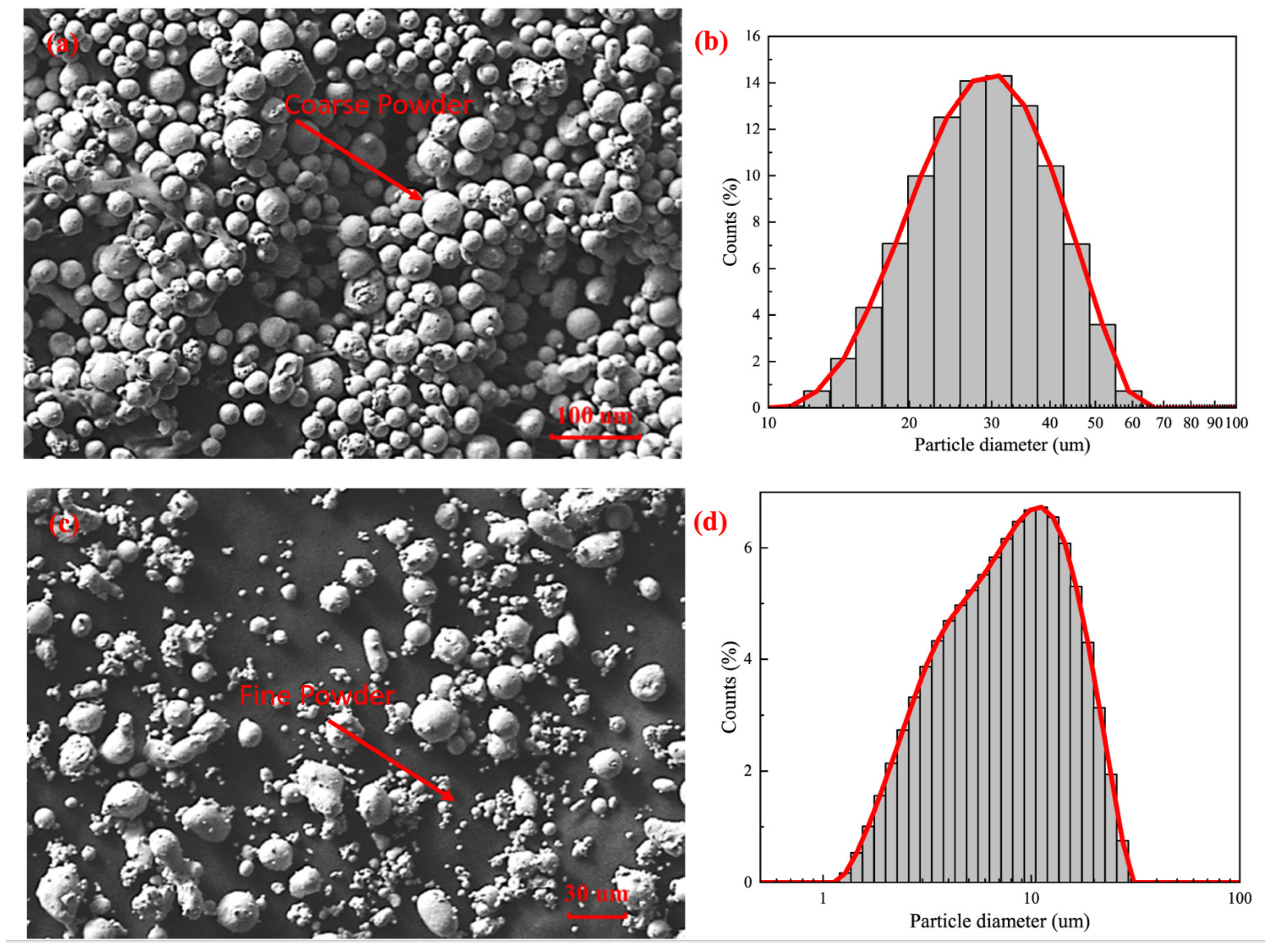
Quite often, the details regarding the specific polymer grades and relative amounts used in filaments for metal FFF remain largely proprietary and restricted, similar to the information related to MIM feedstock. Moreover, most binder systems for metal FFF comprise several polymeric constituents, and this complicates the identification and characterisation of the precise formulations involved. In spite of this uncertainty, binder systems typically consist of three primary components: a main binder, a backbone, and additives. Common binder formulations that are reported in the literature for MIM or metal FFF are shown in Table 1 [58,61,62,67,69,70,71,72,73,74].
The main binder, which accounts for the majority (50–90%) of the polymer matrix in composite filaments for metal FFF, is a low-molecular-weight polymer that decomposes first during the debinding process. The backbone, which can represent up to 50% of the composition, is a high-molecular-weight polymer that helps to maintain the shape during debinding and initial sintering. Additives such as surfactants, plasticisers, or paraffin wax account for a smaller fraction (up to 10%) of the binder, and help to adjust the rheology of the system and improve the filament’s flexibility [29,61,75,76,77]. For example, small amounts of additives like stearic acid or other surfactants increase the melt flow index (which is an index of the “flowability” of the feedstock in the molten state) by inducing a lubrication effect, allowing polymer chains to slide more easily past each other [78,79].
As previously mentioned, it is essential to use multi-component binder systems that can effectively provide the numerous properties that are required of the composite feedstock. For example, Ghasemi-Mobarakeh et al. [80] examined the impact of incorporating high-density polyethylene grafted with acrylic acid (AAHDPE) on the properties of ceramic injection moulding feedstocks (where in principle, ceramic injection moulding works similarly to MIM, just using ceramic powders instead of metal ones). The study revealed that the enhanced powder–binder adhesion enabled by AAHDPE reduced the viscosity of the densely filled composite feedstock. Moreover, the inclusion of AAHDPE favoured powder dispersion, ultimately leading to the improved homogeneity of the feedstock mix.
Similarly to metals, the SDS approach through FFF printing can also produce fully ceramic parts starting from filaments with a high-volume fraction of ceramic particles. Kukla et al. [81] investigated the debinding behaviour of filaments for the fabrication of zirconia parts. They found that higher temperatures increase the debinding rate but also lead to the formation of cracks. The addition of a surfactant (SA) to the binder was crucial to accelerating the debinding rate while also minimising crack formation.
Finally, it is worth noting that the design of the appropriate binder formulation is strongly powder-sensitive, because the fact that a binder can be used for a given metal powder with positive outcomes does not automatically imply that the same binder can also be used for another metal powder. Sadaf et al. [74] observed that copper parts experienced a dramatic shape loss during thermal debinding, even though the same binder had successfully been used to produce stainless steel specimens in previous experiments. The different behaviour of the two metal powder–binder systems was attributed to the higher thermal conductivity of copper compared to stainless steel, and to the presence of elements in steel but not in copper, which may have a possible catalytic effect on the binder.

3.2. Metal Powder

As previously mentioned, a range of metal powders, including SS, copper, Ti and Ti alloys, and Ni-based superalloys, have been investigated for the production of fully metal parts by FFF. Among them, SS and Ti alloys are the most popular options [82]. As an additional advantage of FFF, the SDS approach can also be extended to producing ceramic parts.
The suitability of a metal (or ceramic) powder for metal FFF depends on numerous factors, including its average particle size and particle size distribution, morphology, and specific surface area, as well as on the filler–polymer interactions [70,83].
As previously mentioned, the solid loading in metal FFF filaments typically ranges from 55 to 65 vol.%, as this is key for the obtainment of high-density parts after sintering [27,68,72]. As commonly observed in MIM [84], introducing a higher solid loading leads to debound parts with increased density. This favours the removal of any residual porosity and reduces dimensional shrinkage upon sintering. Although few studies have analysed the effect of increasing the powder content beyond 65%, it is clear that exceeding this threshold can lead to both benefits and drawbacks [61,84]. One of the main challenges is certainly the increased melt viscosity of the metal FFF filament, which makes it difficult to print as is often reported in the literature [58,63,68,76]. As seen before, a possible way around this consists of adding surfactants and other additives that aid in controlling the rheological behaviour.
Besides the filler loading, it is important to note that the powder size and morphology have a substantial impact on the final product’s characteristics [61]. Similarly to those used in MIM, powders for metal FFF are primarily spherical and relatively fine, with an average size below 50 μm [34]. Using finer powders allows for increased solid loading in the feedstock. Moreover, finer particles make it possible to print thinner layers and finer rasters. This leads to an improved surface quality and the ability to produce smaller features [61,84]. As shown in Figure 4, Kan et al. [62] reported that decreasing the average particle size of round SS 316L particles from 30 to 10 μm (while keeping all other parameters constant), resulted in higher solid loading. It was observed in fact that the coarser powder could only achieve a maximum filler loading of 50 vol%, while the finer powder’s loading could reach 60 vol%. Moreover, fine powders offer a larger specific surface area for interaction with the polymer binder and a stronger driving force for sintering. However, to the best of the Authors’ knowledge, nanoparticles are not commonly employed in filaments for metal FFF. This may be due to processability issues, as the presence of nanofillers may strongly change the rheological behaviour of polymer melts [85,86]. Also, particles in metal FFF are due to consolidate into a solid part after sintering, which will cancel out the advantages associated with nanoscale matter.
The powder shape may also influence the physical and mechanical properties of feedstock materials for metal FFF. Wu et al. [87] compared two 17-4PH SS powders, one spherical with an average particle size of 22 μm, and one irregular with an average particle size of 10 μm. The feedstock containing the spherical powder showed better rheological properties during printing, which suggests that round particles may be beneficial for printing parts with high filler loadings. However, in the contribution by Wu et al. [87], the powder morphology and the average particle size were changed simultaneously. Since the improved rheological behaviour may have been induced by either parameter, or even by their synergistic effect, further experiments would be needed to clarify the role of powder morphology in metal FFF, hopefully accounting for all the steps in the SDS workflow.

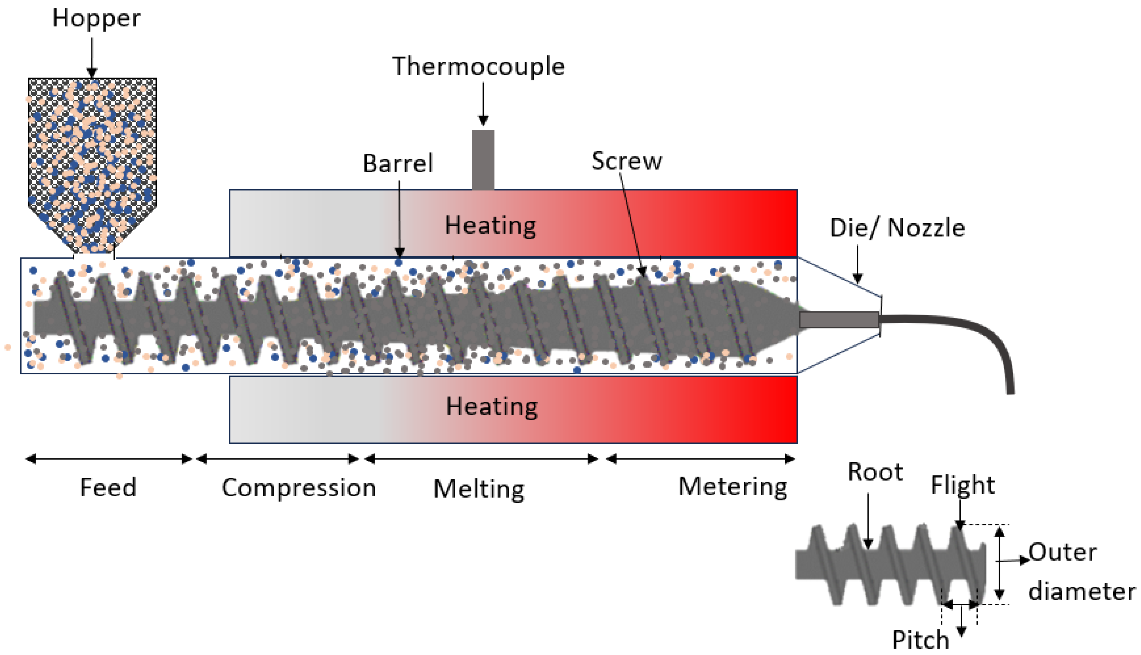
3.3. Filament Preparation

Once the selection of polymer binder and metal powder is decided upon, the next crucial stage in the development of metal FFF feedstock is to melt extrude the filament. One of the major challenges in filament production for metal FFF is achieving a high powder content while maintaining good extrudability and an appropriate flexibility (which is needed for the filament to be spooled and then un-spooled during printing without breaking) [23,72]. As discussed before, filaments with insufficient surfactant or plasticizer, or with very high filler content may also be unsuitable for melt extrusion due to the excessive mixing torque required [76,88].
The characteristics of the filament, such as its density, homogeneity, roundness, and diameter, which all depend on the extrusion process, are fundamental for attaining high quality components in metal FFF. A pore-free filament is essential, as it minimises the risk of breaking during handling and feeding into the liquefier. Furthermore, it facilitates the even and continuous extrusion of material upon printing by preserving a steady pressure during deposition, ultimately leading to an improved green part’s density [23,60].
If the metal powder is not homogenously distributed within the polymer matrix, this can give rise to processing challenges, such as viscosity variations and corresponding pressure fluctuations in the nozzle, also leading to non-uniform printing [70,72,89]. Moreover, local heterogeneities can deteriorate the quality of the final sintered parts by causing anisotropic shrinkage or visible porosity and cracks, since a disproportionate content of binder in a small area may generate large voids during the debinding step that the sintering process cannot eliminate [40].
Another important factor affecting printability is the regularity of the filament in terms of diameter and roundness. Filaments for FFF should have a round cross section, with a tightly controlled diameter (typically, either 1.75 mm or 2.85 mm, depending on the printer). The filament diameter can be assessed during extrusion using laser micrometres or alternative sensing techniques like optical or camera-based systems. Maintaining a constant filament geometry greatly facilitates the printing process [60,67,83]. A filament diameter that is smaller than the specified dimension can be hardly engaged by the feeding system. Also, thin filaments may cause underflow, a phenomenon characterised by suboptimal flow rates and by inconsistent raster width and thickness during deposition. This may ultimately result in inadequate bonding between neighbouring rasters or a formation of voids that will likely persist even after the sintering process [75]. In contrast, if the filament is too thick, it is likely to clog the printer nozzle. Consequently, ensuring precise filament diameter and roundness is crucial for achieving high-quality 3D-printed parts, to the point that an acceptable deviation from the desired diameter is no more than 0.05 mm [23].
The first step for producing a composite filament is to appropriately blend the metal powders with the polymer binder. This can be performed either via batch processing using high-shear mixers like roll mills and planetary or z blade mixers, or via continuous methods like melt extrusion [62,90]. Continuous processes like melt extrusion are preferentially adopted for producing filaments for metal FFF due to their practicality.
In terms of throughput, smaller volumes of feedstock can be produced in capillary rheometers [21,90], while either single- or twin-screw extruders are used for large, industrial scale volumes [62,70]. Twin-screw extruders are more efficient at mixing, whereas single-screw extruders generate a higher extrusion pressure that results in a high and constant throughput [23]. The ability of single-screw extruders to establish a consistent flow even if the feedstock material contains a high filler loading [91] explains why they are often adopted for the final extrusion step in the production of filaments for SDS [92].
A schematic representation of a single-screw extruder is shown in Figure 5. The extrusion process for metal FFF filaments begins with loading the feedstock through a hopper. In principle, metal powder and polymer pellets/granules can be loaded through separate feeders. However, they are often pre-mixed, or even pre-compounded and granulated for the improved homogeneity of the filament. The hopper guides the feedstock into the barrel, which is equipped with heating elements. Inside the barrel, a rotating screw, often referred to as the “auger”, conveys, compresses, and mixes the feedstock as it moves through the extruder. As the screw rotates, the molten feedstock is pushed towards the end of the barrel and forced out through the die, forming a continuous filament. Twin-screw extruders are characterised by the presence of a pair of parallel screws sitting inside a barrel for improved mixing. The die determines the final shape and size of the filament [91]. The filament is then collected on a conveyor belt and finally wound on a spool. Depending on the thermal conductivity of the feedstock, cooling may be necessary at the exit of the spinneret in order to stabilise the filament diameter and shape (roundness) [93]. In-line monitoring may be implemented in order to control the filament diameter and verify the absence of air pockets. Such cavities can negatively affect the mechanical properties of the filament, ultimately compromising its printability [63,94].
The scanning electron microscopy (SEM) micrograph in Figure 6 shows the cross section of a commercially available 17-4PH SS filament. The filament features a very uniform filler distribution and good adhesion at the polymer–metal powder interface. These characteristics are essential prerequisites for effectively handling the filament and ensuring the ease of printing in metal FFF. Shaping the “green” part through FFF printing, followed by debinding and sintering, will be presented in the next section.

4. Shaping, Debinding, and Sintering

As mentioned above, while direct metal printing is feasible with a few LMPAs, most often metal FFF is accomplished through the SDS workflow, which includes shaping (i.e., printing), debinding, and sintering. Also, post-sintering treatments, such as surface polishing or thermal processing, may be required to improve the quality and performance of the metal part. These fabrication stages will be examined step by step in the paragraphs below.

4.1. Shaping (Printing)

Attaining high-quality sintered parts with desirable physical and mechanical properties is heavily influenced by the FFF printing process itself, which corresponds to the “shaping” step. Any gaps between the deposited rasters and other defects in the green part will carry over to the sintered parts, thereby compromising their mechanical performance and functionality. Hence, the control of the printing parameters is decisive in minimising the occurrence of such defects and achieving high-quality sintered parts [38,76,95]. Various commercial printers for metal FFF come with pre-optimised setup parameters for different feedstock types. However, not all filament formulations are accounted for, and it is important to note that these parameters should be adjusted according to the binder composition, and the specific powder used.
A common challenge encountered with metal FFF feedstock is the reduction in mechanical strength and print quality with respect to neat polymers. The strength and quality of an FFF part are primarily dependent on successful inter- and intra-layer bonding, which, in its turn, is influenced by various factors, including material properties and printing parameters [24,96]. Typically, the presence of a high filler loading impairs the polymer chain mobility that is responsible for welding adjacent rasters. However, for a given material, the optimisation of printing parameters such as layer height, extrusion temperature, and printing speed can substantially improve the inter- and intra-layer bonding, as is extensively documented in the literature [41,89,97,98]. The extrusion temperature, which refers to the temperature of the hot-end responsible for heating and softening the filament before deposition, plays the most significant role. In fact, even slight variations in extrusion temperature can impact the mechanical properties and geometric accuracy of the part [99]. In metal FFF, the extrusion temperature largely depends on the binder formulation utilised in the feedstock. An extrusion temperature that is slightly higher than the primary binder’s melting point can effectively reduce the filament’s viscosity, enhancing the deposition process [100]. Meanwhile, thermal-fluid modelling has shown that the thermal conductivity of the filament increases as the metal powder content increases. Thanks to the enhanced heat transfer, under the same nominal temperature set for printing, the average outlet temperature across the molten feedstock becomes higher. This partly counterbalances the ”thickening effect” of the increased filler loading [101].
Among other FFF parameters, the extrusion multiplier (EM) controls the amount of filament that is fed to the nozzle. Increasing the EM can reduce the void content of FFF parts. Higher extrusion rates result in higher inter-layer and inter-raster pressures during printing, and this encourages the molten feedstock to flow and fill the voids. However, excessive extrusion rates can lead to undesirable outcomes, such as dimensional irregularities and uneven surfaces. Therefore, achieving a well-balanced EM is essential for high-quality printing [102].

4.2. Debinding

After printing, the green part still contains the polymer binder, which must be removed before sintering. Clearly, the debinding process aims to remove the binder without disrupting the shape of the green part. However, the complete elimination of the binder is ultimately required, as residual carbon impurities can adversely impact the sintering process and the final quality of the part [103]. To this aim, debinding is usually completed in two steps [78]. During the first step, the main binder is selectively removed, creating pores that facilitate further removal of the remaining backbone constituents during the subsequent debinding phase [77]. Meanwhile, the backbone constituents hold the metal particles together until the sintering process begins, and this ensures that the geometric stability of the part is preserved. During the second step, the backbone is also removed, most often by thermal debinding. Large parts and features with thick sections are particularly difficult to debind, because debinding the core and allowing the debound material to escape may be challenging, and diffusion mechanisms may also be very lengthy [77].
There are several types of debinding processes including thermal, solvent, and catalytic debinding, each differing in their media and process. Thermal debinding is based on controlled heating and isothermal holding at a certain temperature, resulting in either binder evaporation or decomposition [77,104,105]. Solvent debinding is a method that involves submerging a green component in a solvent to selectively dissolve the main binder, ultimately yielding a debound part that only contains the backbone [77]. Catalytic debinding is generally applied to feedstock materials containing polyoxymethylene or polyacetal compounds as the main binder component. This method employs a catalytic acid vapour, like concentrated nitric or oxalic acid, at low temperatures (around 120 °C) to facilitate the removal of the main binder from the green part, reducing thermally induced defects [62,77]. While enabling a relatively fast binder removal, catalytic debinding also improves the debound (“brown”) part’s strength, a crucial aspect during handling operations. Figure 7 shows SEM micrographs of a 17-4PH SS printed part before and after chemical debinding, where the main binder removal can be clearly appreciated.
Oftentimes, multiple polymers with different thermal and chemical properties must coexist in the binder’s formulation for multi-step debinding to be feasible [74]. For example, Wagner et al. [75] developed a multi-component binder system for 316L SS, comprising an LDPE backbone (melt flow rate: 2.63 g/10 min at 190 °C), and a TPE main binder, which enhanced the filament’s flexibility. Stearic acid acted as a surfactant. In order to increase the efficiency of the debinding step, and minimise the fraction of polymer remaining in the printed part after the first debinding step, the filament also contained a high melt flow rate LDPE (70 g/10 min at 190 °C), which was soluble in cyclohexane at 60 °C. As a result, the residual polymer fraction after the first debinding step was as low as 10.5 vol.%. This reduced the risk of distortion during thermal debinding and effectively reduced the presence of carbon impurities coming from backbone residue. The usefulness of this binder system for metal FFF was demonstrated by successfully fabricating delicate 3D lattice structures.

4.3. Sintering

Following the debinding process, the brown parts are sintered in a near-vacuum or controlled atmosphere furnace to achieve full densification [40,75]. Indicatively, the sintering of metals occurs when the temperature exceeds two thirds of the melting temperature of the powder material [106,107]. Initially, weak attractive forces bond particles together, followed by neck growth mainly driven by surface diffusion. The particles gradually merge and the residual pores eventually close, densifying the sintered structure [108]. A two-particle sintering profile is shown in Figure 8, where “D” represents the diameter of the spherical particles with a neck diameter “X” that grows over time [106]. During sintering, the neck expands, driven by capillary forces associated with locally different curvature radii [109].
In practical terms, the final goal of sintering is achieving a density ranging from 95% to 99.5% of the theoretical density. Upon sintering, parts typically undergo a linear shrinkage of around 15% to 20%. To account for this dimensional change, green parts are intentionally designed with an oversized geometry [40,110]. Figure 9 shows the same part, as printed and after sintering, and highlights the change in size due to shrinkage during sintering. It is important to note that shrinkage varies in different directions, with the highest shrinkage commonly observed in the Z (growth) direction, as reported by Thompson et al. [27]. However, deviations may occur due to the influence of the applied printing parameters, such as the layers’ direction, layer thickness, and infill pattern [63,111,112].
The sintering parameters (peak/hold temperature(s), hold time(s), and heating rate(s)) are strongly material dependent. For iron and steel, for example, the sintering temperature usually ranges from 1120 °C to 1350 °C, with a hold time of 1 to 4 h [62,113]. Besides the powder composition, other variables also contribute to a successful sintering cycle, including feedstock characteristics (mainly the particle size) and brown part characteristics (mainly the brown density) [106,114,115,116]. For a given feedstock material, smaller particles require lower sintering temperatures and shorter hold times [114]. Conversely, a lower brown density results in a less effective sintering process due to fewer powder contacts being available in the system [38,117]. Increasing the temperature can reduce the sintering (hold) time but also cause severe distortion. Commercial systems, like Desktop Metal, use a combination of resistance-based and microwave heating to speed up diffusion mechanisms and produce highly dense sintered parts [29,118].
The furnace atmosphere is another relevant parameter, which strongly influences the sintering outcome. Sintering under a non-ideal (i.e., ambient) atmosphere has been attempted in the literature for a matter of practicality [119]. Nonetheless, the most widespread furnace atmospheres in metal FFF are hydrogen, nitrogen, argon, and vacuum [29]. Some feedstocks, such as Ti alloys, require a very specific atmosphere (i.e., Ar or vacuum), since they are reactive with carbon, oxygen, nitrogen, and hydrogen [114]. Even pressure could be applied to speed sintering up, lowering the required peak temperature(s) and favouring the densification of the parts.
Finally, it is worth mentioning that a controlled cooling rate after sintering may be necessary to accommodate possible phase transformations occurring in the sintered part [75]. Completing the cooling step in a protective atmosphere is preferred to avoid oxidation.

4.4. Post-Sintering Processing

Post-sintering processing is crucial to optimising the characteristics of metal FFF parts, encompassing surface properties and visual appeal, contingent upon the specific application of the printed part.
Bead blasting represents a relatively simple method capable of enhancing surface texture, mainly because it eliminates sharp edges produced by stair-stepping artefacts. In scenarios where a polished or smooth finish is mandated, supplementary steps involving wet or dry sanding and polishing may be required [98,120]. Manual cleaning methods, including brushing or air blasting, can also be used, though these require more labour and skill than fully automated ones. For some intricate or delicate features, precision finishing techniques, such as micro-abrasive blasting, laser polishing, or electropolishing, may be used to refine the part’s surface.
There can be challenges when applying post-sintering processes to parts with complex geometries or lattice structures, primarily due to the difficulties in accessing all areas of these structures and the inherent fragility of such complex forms. However, several strategies can be used to mitigate these issues. Primarily, the post-processing requirements can be proactively considered during the design stage of the part. This may include incorporating features that facilitate cleaning, polishing, or other post-processing operations. For example, a structural connectivity control method is applied to eliminate closed voids obstructing the removal of support structures by identifying potential paths connecting these voids to the part’s surface [121].
Sintered parts can be heat-treated to further improve their mechanical properties and relieve residual stresses. However, trade-offs may be necessary. For example, Vijaya Kumar and Velmurugan [122] observed that the density and the elongation at break of 316 L SS parts increased after thermal treatment, but the strength decreased. Moreover, the as-printed parts displayed better wear resistance than the heat-treated specimens due to heat-induced surface softening.
Recent investigations [123,124] have explored the feasibility of using hot isostatic pressing (HIP) sintering to remove residual pores and enhance the mechanical properties of 316 L SS parts. The results demonstrate that the application of controlled pressure in an argon atmosphere at 1320 °C for 1 h after sintering in vacuum reduced the residual porosity, resulting in a high ultimate tensile strength of 540 MPa, and significantly alleviated anisotropic effects. Additionally, the microstructure of HIP-sintered parts exhibited equiaxed grain morphology. This is just an example of the potentialities of metal FFF, which may lead to metal parts with excellent mechanical properties, comparable to those of parts produced by PBF or PFF, while also bypassing some limitations of these techniques like the preferential growth of columnar grains [63,123].

5. Prevalent Metals and Alloys in Metal FFF

Thanks to the progressive amelioration of the printing–debinding–sintering workflow, potentially completed by post-processing treatments as described above, metal FFF has already found diverse applications spanning various industry sectors, as illustrated in Figure 10. Notable examples include biomedical implants, automotive components, and consumer goods, such as intricately shaped pure copper electrical elements, catalytic supports, and heat sinks [32,125,126,127,128]. However, the palette of commercial filaments for metal FFF is still very limited. MIM offers a wide range of feedstock materials, and these materials should, in theory, also be applicable to metal FFF. Nevertheless, not all MIM feedstocks have been tested for this purpose, and the restricted number of metals and alloys being used in metal FFF calls for additional research in the future to bridge this gap.
Although other metals and alloys have been explored in the literature, including metallic glasses, magnetic materials, and high entropy alloys [129,130,131], the following sections discuss the range of metals and alloys that have been processed most commonly utilising state-of-the-art metal FFF technologies.

5.1. Iron and Steel

Many types of steel have been successfully manufactured by metal FFF, such as SS, tool steel, and maraging steel. Among them, SS is particularly popular owing to its remarkable properties. SS is a corrosion-resistant alloy that consists of chromium (Cr), Ni, and occasionally other elements like molybdenum (Mo) and Ti [132]. SS exhibits high strength and excellent ductility, and when 3D printed, SS parts can receive complex and intricate geometries.
As summarised in Table 2, the two most common grades of SS used in metal FFF are 316L and 17-4PH [27,34,95,133,134,135,136,137].
316L SS is a low-carbon version of 316 SS, which is a Mo-bearing austenitic SS. Owing to its outstanding corrosion resistance, 316L SS is commonly utilised in marine, aerospace, and medical applications, such as surgical instruments and valves [16,132]. An example of 316L SS tensile specimens produced by metal-FFF is shown in Figure 11 [16]. In a recent study by Sadaf et al. [34], 316L SS filaments were extruded using a single-component binder (LDPE). The adoption of a single-component binder formulation may provide a more sustainable and cost-effective solution for metal FFF than conventional multi-component binders, because it streamlines the filament production. Moreover, the single-component formulation makes it possible to use a recycled polymer (in this case, recycled LDPE) as the binder. The sintered parts exhibited well-densified austenitic grain structure with excellent mechanical properties, including a yield strength of ~250 MPa, and a tensile strength of 520 MPa, which were comparable to parts produced using MIM despite the presence of residual porosity resulting from the FFF process. These findings provide new opportunities for affordably producing steel parts with complex geometry.
The study conducted by Kurose et al. [95] examined the effect of the printing parameters, specifically raster direction and layer thickness, on the relative density of 316L SS parts. The results indicated that the relative density after sintering was notably higher when the green parts had been printed with a layer thickness of 0.1 mm compared to 0.3 mm. Conversely, the raster orientation had minimal influence on the relative density of the printed parts. The highest relative density achieved in this study was 92.9%.
As for 17-4PH SS, this is a precipitation-hardening SS that contains 17% of Cr and 4% of Ni. It also contains 4% of copper (Cu) and 0.3% of niobium (Nb) [28,113]. It has excellent strength, and good corrosion resistance. In metal FFF, 17-4PH SS is often used to produce parts that require high strength and wear resistance, such as bearings, pump components, and moulds. Intricate patterns are also feasible, as demonstrated by the auxetic structures in Figure 12 [138]. Suwanpreecha et al. [134] investigated the influence of the specimen layout while printing 17-4PH SS components by metal FFF. Their results demonstrate that parts printed flat on the base platform and parts printed on a side consistently exhibit superior tensile properties in comparison to vertically oriented samples. In turn, parts printed flat on the base platform have better tensile properties than parts printed on a side. This difference in tensile properties associated with different printing layouts is primarily attributable to the presence of printing voids and relatively weak layer–layer interfaces. Notably, when the loading direction aligns with the printed layer, the tensile properties are mainly influenced by the presence of pores. Conversely, when the loading direction is perpendicular to the printed layer, the main cause for failure under tensile loading is layer delamination. A recent contribution by García-Cabezón et al. [137] compared the tribocorrosion behaviour of 17-4PH SS parts produced via metal FFF, MIM, or conventional powder metallurgy (PM) methods. Even though the MIM samples achieved the highest macro- and micro-hardness, the corrosion behaviour was comparable for both the MIM and metal FFF samples, largely surpassing that of conventional PM benchmarks. Interestingly, the as-fabricated metal FFF samples exhibited a significant improvement in tribocorrosion resistance, which was attributed to the high ratio of delta ferrite and retained austenite in their microstructure.

5.2. Ti and Alloys

Ti and Ti alloys are known for their high strength-to-weight ratio, corrosion resistance, and biocompatibility, making them attractive materials for aerospace, automotive, and biomedical applications [63]. More specifically, Ti-6Al-4V has received more attention than any other alloy due to its outstanding strength-to-weight ratio. Zhang et al. [111] developed Ti-6Al-4V filaments with 55–59 vol.% of powder loading using a polyolefin-based binder system. The correlation between sintering temperature and microstructure was investigated using XRD. It was found that the ratio between α- and β-phase could be controlled by varying the sintering temperature, since the β-phase content decreased from 15 to 11 vol.% when the sintering temperature was increased from 900 to 1340 °C. Moreover, the metal FFF samples possessed a non-orientated grain growth structure, meaning that the randomly oriented grains in the original powder grew upon sintering and formed a randomly oriented solid structure [111]. This represents a remarkable difference from Ti alloy samples produced by PBF and DED, which generally experience columnar growth and show strong anisotropy along the build direction [18].
The findings of the study conducted by Warner et al. [31] suggest that metal FFF of Ti-6Al-4V holds promise as a cost-effective alternative to conventional manufacturing techniques for fabricating components for gas turbines and compressors. Nonetheless, additional research is required to further promote densification and enhance the quality of thin walls.
Singh et al. [139] investigated the critical aspects of processing Ti-6Al-4V via metal FFF, including filament extrusion conditions, printing parameter optimisation, sintering time and temperature, and powder attributes (size and interstitial concentrations). The authors found that the extrusion multiplier significantly impacted the sample’s density. In fact, as previously mentioned, the extrusion multiplier (also known as the flow rate multiplier) controls the amount of material extruded by the 3D printer’s nozzle during the printing process. In its turn, the flow of material dictates the green part’s density. As expected, it was found that the sintering time and temperature deeply affected the density and the mechanical properties of the sintered samples. A higher temperature and a longer time resulted in improved density and strength but also caused higher oxygen pickup, and hence lower elongation at break. Additionally, finer powders resulted in higher density and strength but also led to lower elongation at break than coarser powders due to higher oxygen concentration. The paper by Singh et al. [139] finally demonstrated that metal FFF, if properly conducted, can produce Ti-6Al-4V samples with properties comparable to MIM and other conventional processes. However, reducing the residual porosity is key to achieving reliable structural components, since the presence of pores significantly reduces the elongation at break, and this may cause premature failure under tensile load [140].
Examples of research papers investigating the metal FFF of commercially pure Ti (CP Ti) and Ti-6Al-4V are summarised in Table 3 [31,111,139,140].
The use of metal FFF for Ti alloys has a significant drawback in that Ti is highly sensitive to interstitial elements, particularly oxygen. Complete isolation of the Ti samples from oxygen during handling, including the sintering process, is difficult. The uptake of oxygen is known to be harmful to the mechanical properties of the final products [116,139]. Therefore, it is necessary to strike a balance between cost-effective fabrication (under mild atmosphere conditions) and meeting property requirements for specific applications (needing the complete exclusion of oxygen before embedding the Ti powder in the polymer matrix, and during sintering).

5.3. Ni Superalloys

Ni superalloys are highly sought after for their excellent high-temperature properties and corrosion resistance, making them a popular choice for high-temperature and high-stress environments, such as jet engines and gas turbines. A special Ni alloy is Nitinol, which is a shape memory alloy (SMA) that has many critical applications, such as self-expanding stents for cardiovascular surgery replacements [141]. Table 4 provides a summary of contributions in the literature exploring the metal FFF of Ni alloys (mainly Ni-Ti alloys) [30,142,143,144,145].
In recent years, metal FFF has emerged as a promising technique due to its ability to process different Ni-based alloys and produce intricate or bespoke parts without the need for complicated machining. Owing to the high strength, toughness, and hardness inherent to Ni-based alloys, machining complex geometries from wrought material becomes economically challenging. AM methods represent a viable near-net-shape manufacturing technology, offering an alternative or complementary solution for producing superalloy components. Nonetheless, the fabrication of Ni-based superalloys through PBF or LMD still presents numerous difficulties, such as elemental micro-segregation and the build-up of thermal and residual stresses during processing [30,142]. Conversely, various Ni alloys have been successfully printed using metal FFF, such as Inconel 718 [30], Inconel 625 [142], and various NiTi alloys [143,144,145].
Inconel 718 (IN 718) is the most utilised and researched Ni-based superalloy. Thompson et al. [30] investigated the potential of metal FFF as an affordable technology for producing IN 718 components. They observed that carrying out both thermal debinding and sintering under vacuum effectively prevented grain boundary oxidation, yielding a high relative density above 97%. By optimising the metal FFF process, they were able to meet the mechanical requirements set by AMS 5917 for MIM production [146], and demonstrated that the creep behaviour of metal FFF parts under compressive loading is comparable to that of reference IN 718 parts produced by conventional manufacturing methods.
In their study, Wagner et al. [143] applied metal FFF to NiTi SMAs. They characterised two distinct NiTi alloys with a focus on their microstructure and thermo-mechanical properties, with one alloy (NiTi-1) displaying super elasticity and the other one (NiTi-2) exhibiting shape memory properties at room temperature. After undergoing a 4% strain, NiTi-1 demonstrated a super-elastic strain recovery of 1.2%, while NiTi-2 exhibited a shape memory strain of 1.9%. These values are lower than those reported in the literature for samples produced with conventional technologies, suggesting potential room for improvement through the optimisation of the binder composition and the sintering conditions. Additionally, the study explored specific actuator geometries to enhance shape memory strain. Overall, in spite of the relatively low values recorded, this research confirms the suitability of metal FFF for the fabrication of SMA structures, often referred to as 4D printing.

5.4. Other Metals and Alloys

Other metals and alloys, such as Cu, Al alloys, magnesium (Mg), and tungsten-based alloys, are also being explored in metal FFF, thus gradually expanding the material portfolio.
Pure Cu is commonly used in electronic, electromagnetic, and heat management applications due to its excellent electrical and thermal conductivity, as well as its high workability and solderability. A Cu inductor fabricated by metal FFF is shown in Figure 13 [147]. Metal FFF is being explored to enable the production of more complicated copper parts than those conventionally produced by MIM and other metal processing methods [74].
The PBF of Cu, which historically has been mainly accomplished by SLM, is challenging due to the high reflectivity of Cu to conventional laser beams. Metal FFF sidesteps the laser-related issues [37] and enables the production of complex-shaped Cu components, such as antennas, inductors, and radiators [148]. Gonzalez-Gutierrez et al. [149] noted that, despite having lower mass, Cu samples possessing a thin external wall showed similar flexural characteristics compared to samples without an outer wall. This may offer key advantages in the fabrication of lightweight components, notably in electronics, transportation, and the aerospace industry. Copper alloys such as bronze can also be built successfully by metal FFF [150]. Wei et al. [151] observed that the density, mechanical properties, and surface quality of bronze parts produced from a CuSn10/PLA composite filament largely depended on the printing parameters, especially the raster overlap. Increasing the debinding rate to 0.5 °C/min and setting the sintering temperature to 860 °C led to the highest density (8.08 ± 0.29 g/cm3), with an electrical conductivity coefficient of 4.9 × 10⁶ S m−1, corresponding to 84.48% of the normal electrical conductivity coefficient of bronze [151].
Being lightweight high-strength alloys with excellent corrosion resistance, Al alloys are widely used in the aerospace and automotive industries. The PBF and DED of Al alloys are still hampered by the poor absorption of laser energy and the limited weldability of Al alloys. While metal FFF avoids these issues, certain challenges still remain. In particular, Al powders are very sensitive to oxygen and easily become coated with a stable Al oxide film. This coating can impede proper sintering and lead to defects such as porosity and cracks, thereby preventing the achievement of fully dense parts [106]. Momeni et al. [152] investigated the thermal, mechanical, and rheological characteristics of Al feedstock for metal FFF. Their findings revealed that metal FFF could effectively manufacture robust Al components, given the use of appropriate sintering parameters. Also, various polypropylene-based binders were employed in order to evaluate the effect of the binder’s backbone on the suitability of feedstocks for metal FFF. The authors concluded that, among the different systems in exam, the binder combining TPE and PPMA was the most suitable for the metal FFF of Al parts. However, the authors suggested that further investigations into the debinding and sintering behaviours of the feedstocks would be needed to achieve fully dense and defect-free Al parts.
Examples of Al- and Cu-based alloys can also be found in the metal FFF portfolio. Al- and Cu-based alloys are popular in aircraft, automotive, and aerospace applications due to their relatively low weight, high strength, and plastic properties. In order to combine the advantages of these alloys with the versatility in the geometry of AM, Lozhkomoev et al. [153] produced an Al–Cu bimetallic powder (copper content of about 10%) by a simultaneous electrical explosion of Al and Cu wires in an Ar atmosphere. Composite feedstock for metal FFF was obtained adding the powder to a polymer binder based on polyamide and polyol-ester (polymer ratio of 1:5 in mass). The metal filler loading was around 89 wt.%. After debinding, the samples were sintered at 560 °C for 1, 4, and 6 h. It was observed that the relative density increased from 68.1 to 94.6% as the sintering time increased from 1 to 6 h, which led to improved microhardness, compressive strength, and bending strength [153].
Mg alloys are another class of lightweight materials that are frequently employed in the production of bioimplants. For example, Wolff et al. [154] were able to effectively manufacture demonstrative implants made from Mg alloy using metal FFF. The printed samples displayed mechanical properties comparable to those observed in cast samples, which led to the conclusion that FFF could be a highly effective method for fabricating Mg-based implants.
Bose et al. [51] reported preliminary investigations regarding the processability of a tungsten-heavy alloy (WHA) by metal FFF. Owing to their exceptional combination of high density, strength, hardness, and toughness, WHAs are employed in a wide range of applications, such as counterweights, sporting goods, radiation shields, and vibration-dampening devices. The investigation conducted by Bose et al. [51] demonstrated the ability of the Bound Metal Deposition (BMD) process, a variant of FFF, to fabricate complex-shaped parts from liquid-phase sintered WHAs having a composition of 93 wt.% W and containing Ni and Fe. The metal FFF parts achieved comparable properties to WHA samples processed by conventional technologies. Meanwhile, the capability of producing complex geometries with fine features without any tooling by metal FFF opens up new opportunities for the wider diffusion of this class of alloys.
Clearly, metal FFF represents an effective solution for the additive manufacture of various metal and alloy systems. However, research is still needed to overcome technology limitations and challenges as a crucial requirement for the wider adoption of this technology in industry.

6. Challenges and Critical Considerations in Metal FFF

To effectively implement metal FFF within industrial settings, a thorough understanding of the potential obstacles, material-related unknowns, processing challenges, and potential supply chain issues must be considered during the initial decision-making stages of product development [15,132]. Furthermore, metal FFF poses challenges in terms of achieving the desired surface finish and dimensional accuracy, as further discussed below.

6.1. Material-Related Challenges

A significant challenge in the development of filaments for metal FFF lies in tailoring the binder system to accommodate diverse fillers that vary by chemical composition, particle size, and morphology [61,63,83]. In this regard, it is crucial to note that different metal systems require different binders. Even for a given metal or alloy, powders having different particle size distributions may require their own specific binder system [21,88]. Furthermore, additional studies are needed to formulate advanced binder systems that are environmentally friendly while preserving the ease of processing. Regarding the binder formulation, is it worth repeating that one of the main barriers to the advancement of metal FFF is the obscurity that surrounds this topic in the literature. It is reasonable that the binder composition is considered highly confidential by those businesses (such as Markforged, Desktop Metal, UltiMaker/BASF, or The Virtual Foundry) that commercialise metal filaments, because this is at the core of their intellectual properties. As such, the details of the binder are oftentimes legally protected and patented. However, it appears more surprising that information about experimental binders is rarely disclosed in scientific papers. It is generally understood that the experimental section of a research paper should give as many details as possible in order to enable the reader to repeat the experiment. This should be a prerequisite for ensuring the transparency of the published work, for avoiding the repetition of failed attempts, and finally for nourishing future research. Nonetheless, it is common practice to keep the binder’s composition hidden when it comes to metal FFF, even though this obviously undermines any chance of repeatability. Akin to Table 1 in Section 3.1, inventories of binder formulations have been tabulated in various review papers, such as the contributions by Sola [23] and by Gonzalez-Gutierrez et al. [76]. While certainly useful as a starting point for the design of new binders, these collections are unavoidably partial, as they all clash with the secrecy of the archival literature.
The feedstock material also determines the processing equipment required, especially for debinding and sintering. Although the shaping step in metal FFF may be more difficult than “normal” polymer printing because of the high filler loading, printing the green part is generally recognised as a relatively easy task, which may be accomplished even on a desktop FFF printer. Accordingly, the most demanding steps in terms of equipment are the debinding and sintering operations, as they may need dedicated facilities. In the case of refractory metals, sintering the brown parts requires a high temperature of around 2500 °C (depending on the metal) and a controlled atmosphere [106], which means that specialised furnaces and skilled operators are strictly necessary to run such processes. Notably, some filaments’ producers are now offering debinding and sintering services for their customers. This is the case, for example, with BASF, which has initiated the Debinding and Sintering Order Management Portal in Europe [155]. The possibility of externalising the debinding and sintering operations as the most cumbersome stages of the SDS process may allow small enterprises and even private individuals to easily produce their own metal parts with nothing more than a normal FFF printer. This may be extremely convenient if metal components must be printed as a one-off, or if preliminary testing is needed to confirm the adequacy of the technology before investing in new equipment. However, as a downside, it should be recognised that service providers only deliver the final metal object, without revealing how this was fabricated. This may ultimately impede the achievement of a sound comprehension of the material–processing–microstructure–performance relationships, thus contributing to the above-mentioned opacity of the literature regarding metal FFF.
Again, in terms of material-related challenges, it is worth noting that metal FFF parts may be anisotropic. For example, as already mentioned, according to the tensile tests conducted by Suwanpreecha et al. [134], the ultimate tensile strength of 17-4PH SS decreased from 1034 ± 3 MPa for the specimens printed flat on the base platform, to 978 ± 5 MPa for the specimens printed on a side, to 745 ± 6 for the samples printed upright (vertical layout). Likewise, the Young’s modulus decreased from 176 ± 5 GPa (flat) to 163 ± 2 GPa (side) to 159 ± 6 GPa (vertical). Similar trends were also reported by Abe et al. [136]; however, the tensile strength values were significantly different, being 880 MPa for the flat layout, 840 MPa for the side layout, and 780 MPa for the vertical layout. Clearly, the lower performance commonly recorded along the vertical direction is a consequence of the layer-wise build-up mechanism that underpins FFF printing. The strong variability in mechanical properties observed in the literature may have two reasons. Firstly, mechanical properties depend on the processing conditions and parameters. For example, assuming that the tensile behaviour of the green parts will translate to a similar behaviour of the finished parts, Godec et al. [135] proved that the strongest influence on the tensile properties was exerted by the flow rate multiplier, followed by the layer thickness and finally by the extrusion temperature. Godec et al. [135] also concluded that maximising all these three parameters would result in the highest tensile properties of the green parts. Further to this, mechanical data in the literature lack consistency because there exists no standard method for measuring them.
Finally, it should be observed that most scientific contributions only focus on the tensile performance of metal FFF parts, while other mechanical properties (e.g., compression resistance, bending behaviour, fracture toughness, fatigue) and functional characteristics (e.g., electric and thermal conductivity and corrosion resistance, just to name a few) are largely underexplored. The tensile properties, in their turn, can hardly be compared across the literature for the reasons mentioned above.

6.2. Process-Related Challenges

Addressing process-related challenges in metal FFF is essential to obtaining high-quality parts with minimal distortion and high dimensional accuracy. As previously discussed, several factors must be considered in order to achieve optimal results, including high powder loading, homogeneous powder–binder distribution, adequate filament stiffness, reduced viscosity during printing, appropriate printing parameters, staged pre-sintering binder removal, an adequate sintering cycle, and a controlled atmosphere [38,46,93,96,156,157].
In metal FFF, the part may warp or even crack upon sintering as a consequence of anisotropic shrinkage due to the layer-wise build-up mechanisms that are typical of 3D printing. For example, for SS parts, the shrinkage rates were observed to be strongly anisotropic, with the value measured along the build direction being the largest, and the other two values measured parallel to the build platform being closely similar to each other [158]. To clarify, in the research conducted by Léonard and Tammas-Williams [158], 17-4PH SS prisms (20 mm high and 8 mm wide) were printed, debound, and sintered on a commercial Markforged platform. X-ray Computed Tomography (XCT) measurements revealed that the shrinkage values ranged between 15.14% and 15.20% for the in-plane directions, against 15.46% for the growth direction. This difference was tentatively attributed to the anisotropic structure of FFF parts, which are made layer by layer along the growth direction, and raster by raster within individual layers [158]. Moreover, it was observed that oftentimes the growth direction upon printing and the vertical axis upon sintering coincide. This means that anisotropic effects may also be made stronger by the force of gravity [158].
Ultimately, anisotropic shrinkage appears to be inevitable [76], and warpage may be exacerbated by temperature gradients in the furnace. However, sintering-induced distortion can be largely mitigated through the appropriate design of the printhead toolpath; for example, by alternating the perimeter direction layer-by-layer, as demonstrated by Abel et al. [159]. While very effective, this mitigation strategy was primarily developed for the production of porcelain objects, and was inspired by the observation that the main deformation occurred while debinding in acetone. Notably, it also worked for other materials, such as alumina and 17-4PH SS. However, further testing would be needed to confirm its efficacy with other metals and alloys, especially when the binder should be removed through different debinding procedures, and when the part deformation would be mainly caused by sintering, rather than by debinding.
On account of the similarity existing between metal FFF and MIM, the sintered parts can be rectified using conventional metalworking processes such as heat treatments or surface treatments. On the other hand, this additional step would consume time and energy, thus impairing the practicality of metal FFF.
Another point needing attention is the presence of residual pores in the sintered parts. Defects can be classified in two broad categories as printing-associated pores and sintering-associated pores. As for printing-associated pores, it has been reported that potential defects in the green part (for example, inter-raster gaps caused by insufficient overlap or voids caused by printhead blockages) will carry over to the brown part, and in the end, to the final part [158], because large pores cannot be closed upon sintering [76]. As for sintering-associated pores, in principle the part’s density can increase up to 99% of the theoretical value at the end of sintering. However, full (viz. 100%) density cannot be achieved, because some pores become isolated and cannot be removed [76]. Moreover, as a result of the long residence time at a high temperature, grain growth is also triggered upon sintering, and this hampers the sintering process, reducing the densification rate [76].
For high-value parts, HIP can help to completely remove any residual porosity, provided that the approach is compatible with the geometric complexity of the component [160]. Interestingly, the residual porosity can be filled with a second material through a post-sintering infiltration process. This strategy has proved to be convenient for the production of metal matrix composites by MIM [161]. Examples of post-sintering infiltration already exist in the realm of fully inorganic parts obtained from FFF-printed parts, such as the glass-infiltrated alumina parts developed by Arnesano et al. [162]. Obviously, the infiltration approach results in a bi-material system, and the two constituents must be properly chosen. For example, coupling two dissimilar metals in the same part may cause unintended galvanic corrosion, particularly in a humid environment. Moreover, if the infiltration is completed by melting the second material, the temperature must be kept below the melting temperature of the base metal in order to preserve its geometry and architecture.
Metal FFF parts with high geometric complexity present unique obstacles during debinding and sintering stages, especially when it comes to preserving the structural integrity of small parts and the stability of vertical components. Large parts or bulky structures may be equally difficult and lengthy to debind and sinter.
Even if, in principle, AM is a near-net-shaping technology, post-processing treatments in metal FFF may be required to ameliorate the mechanical properties, improve the aesthetic appearance, and relieve residual stresses after sintering [111,120]. Besides the removal of support structures, such measures encompass surface finishing, stress alleviation, machining procedures, and may employ heat treatment or HIP to counteract print-induced imperfections, including incomplete fusion and porosity [123].
Support structures require special attention. These features are crucial to achieving the desired part’s geometry and dimensional accuracy, as overhangs can cause sagging and deformation during printing [163]. Intuitively, support structures continue to play a critical role during sintering, as they help maintain the stability and shape of the part. However, support structures can be difficult to remove, resulting in surface roughness and damage to the part. Commercial metal FFF systems like Markforged Metal X and Desktop Metal Studio 3D use special ceramic support materials [35], such as ceramic release layers, to facilitate the production of metal parts with complex geometries. These ceramic materials are formulated for support structures to be easily removed after printing, leaving behind the metal part unaffected, and are helpful to prevent deformation and warping during the printing process. Managing the support structures becomes more challenging when metal FFF does not proceed through commercial systems, because the supports and the main geometry are likely printed with the same feedstock. Under these circumstances, the ability of the product’s developer to design the part is crucial. The part’s design must consider the optimal placement of the support structures to minimise their impact on the part quality and to enable post-processing. The orientation of the part during printing also influences the part quality, strength, and dimensional accuracy, and the optimal orientation is one that minimises the need for support structures and maximises the part quality and properties.
Different AM processes exhibit different dimensional accuracies. Moreover, the fabrication parameters within the same AM process affect the dimensional accuracy. Numerous published studies have explored the dimensional accuracy of metallic components manufactured through FFF [113,164,165,166,167]. For instance, Wang et al. [166] reported that factors such as layer thickness, raster angle, raster width, and infill density strongly affect the dimensional accuracy of metal FFF parts, which is consistent with the literature regarding polymer-based FFF [165,168]. According to Wang et al. [166], the layer thickness is the main factor governing the dimensional accuracy, which improves as the layer thickness decreases. This triggers mutually conflicting trends though, because as the layer thickness decreases, the number of layers required to complete the part increases. This leads to a longer printing time and to worse energy consumption.

6.3. Production Volume

Metal AM is mainly sought after for the production of customised items featuring intricate geometries in low-volume production. Conversely, “conventional” manufacturing methods tend to offer more affordable options for high-volume needs. This mainly happens because traditional manufacturing processes experience a significant drop in cost per part as the production volume increases [169]. For instance, forging and injection moulding exhibit high overhead costs, and this makes them cost prohibitive at low volumes. However, their per-unit cost diminishes significantly at higher volumes. In contrast, metal 3D printing, and especially metal FFF, are associated with lower overhead costs. However, in metal FFF (like any other AM technology) the per-unit cost remains almost independent of the production volume, with minor benefits associated with economies of scale coming from the potential sharing of auxiliary tooling and fixture costs. This means that metal FFF is mainly suitable for low-volume production. Indicative cost/volume curves are compared in Figure 14. It should be noted, however, that numerical values are not specified on the Cartesian axes because the overhead cost may notably change for different technologies. As for the metal FFF equipment, for example, the capital expenditure significantly changes if the company is interested in purchasing the whole production line (typically including printer, debinding unit, and sintering furnace), or if the post-printing operations required for debinding and sintering are externalised. Also, the breakeven point may be affected by the size and geometry of the components to be produced, as they affect the build time, and hence, the energy consumption. To exemplify, Sæterbø et al. [170] developed a multi-objective optimisation model to account for costs and emissions along the supply chain. Analysing an industrial part made of stainless steel 17-4PH as a real case study, the comparison between metal FFF and CNC machining across four different production scenarios including 10, 100, 1000, and 10,000 parts demonstrated that metal FFF is cost competitive at low volumes, up to 10 identical parts. However, the equilibrium point is affected by the achievement of optimal production operations, wherein the production volume must be large enough to eliminate idle times. Notably, sintering emerged as a cost driver in metal FFF, suggesting that cost efficiency is governed by this step, rather than by the printing stage. While comparative cost advantages over traditional manufacturing are eroded by increasing production volumes, unit carbon emissions (per part produced) drop thanks to the economies of scale [170].
Finally, producing a part by metal FFF varies in time due to factors like part’s size, and complexity, and printer used. Metal FFF offers design flexibility but is generally slower than conventional methods for high-volume production due to the layer-by-layer build-up of the green part. Moreover, additional steps like debinding and sintering (and sometimes, post-processing) are needed after printing, and this may increase the lead time. Despite this limitation, the implementation of metal FFF in mass production is on the rise, driven by recent technological advancements that increase its productivity [4,21,157].

6.4. Minimum Feature Size

In metal FFF, several factors influence the minimum feature size (i.e., the smallest size that can be printed), including nozzle diameter, layer height, and print resolution [21,63]. The nozzle diameter determines the minimum width of the printed line (viz. individual raster), while the layer height dictates the minimum thickness of the printed layer. The print resolution, on the other hand, determines the minimum distance between two adjacent printed lines. Besides the nozzle diameter and the layer height, the print resolution is influenced by multiple components and settings of the FFF printer in use, including the XY precision (the precision with which the printhead can be moved in the X and Y axes on the gantry), print speed, and Z-axis movement control [171,172].
Attempting to print features that are smaller than the minimum feature size may lead to poor quality, such as rough surfaces and weak bonds between subsequent layers [63,76,142]. In metal FFF, it is crucial to consider not only the factors that affect the minimum feature size during printing but also the subsequent processes of debinding and sintering. Sintering, in particular, introduces its own set of considerations, as it typically involves a linear shrinkage of about 15% [106]. Consequently, all dimensions of the printed part will reduce in size during the sintering process. While this shrinkage can affect various features, it poses a particular challenge for intricate or fine details, which may become distorted, break, or collapse.

6.5. Maximum Part Size

While the typical build volume of desktop FFF printers is around 200 × 200 × 200 mm3, industrial machines can reach larger sizes of 1000 × 1000 × 1000 mm3 [173]. Larger parts can be built fitting an FFF printhead on a robotic arm [174]. Albeit processing pellets instead of filaments, the big area additive manufacturing (BAAM) system can accommodate structures measuring 6 m in length, 2.4 m in width, and 1.8 m in height [175]. Concerning metal FFF, however, the main limitations to the part’s size come from the post-printing operations [176]. Naturally, the debinding unit and the sintering furnace must be large enough to receive the part. Moreover, debinding becomes very challenging with thick structures, due to the potential build-up of outgassed decomposition compounds. Shrinkage and warpage are also aggravated in large parts. As a result, the typical size of metal FFF components does not generally exceed 200 mm, as seen for desktop printers. As already discussed, the actual size of the finished part will be smaller after sintering.

6.6. Surface Finish

FFF parts are often blamed for presenting a high surface roughness, which is due to the relatively high thickness of individual layers [177,178], and this defect may carry over to metal parts produced by metal FFF. In addition to the aesthetic properties, the surface finish also affects the mechanical performance of metal FFF parts. In principle, the poor surface quality may even hinder the applicability of metal FFF whenever tight clearances are needed; for example, in the fabrication of tools in the mould-and-die industry. However, Kain et al. [179] tested 17-4 PH SS die inserts (produced from composite rods instead of conventional filaments) for the extrusion of ABS, and observed that the three-dimensional average roughness, Sa, of the ABS extrudates fabricated with the AM die (in the rage of 0.5 μm) was actually similar to that of analogous ABS extrudates produced with conventionally machined dies (in the range of 0.3 μm). This was an unexpected result, given that the Sa of the FFF die insert (2–9 μm) was much higher than the Sa of the dies manufactured via CNC machining and electrical discharge machining (0.3–0.9 μm) [179].
Factors that impact surface finish include filament diameter consistency, extrusion temperature, bed adhesion, layer height, and post-processing treatments. To improve surface finish, it is recommended to use high-quality filaments with uniform diameter, optimise the extrusion temperature for a smooth flow of the molten feedstock, and ensure proper bed adhesion to prevent warping and distortion. Relatively low printing speeds may favour smoother surfaces, because a progressive lack of infill between adjacent printing lines (rasters) has been observed with increasing printing speeds [73]. Thinner layers also produce smoother surfaces but increase printing time, and post-processing techniques such as polishing and sandblasting can further improve surface finish as already discussed in Section 4.4.

6.7. Sustainability

Despite the encouraging results published by Sæterbø et al. [170] regarding the carbon emissions, more research should be dedicated to evaluating the consequences of metal FFF on the environment. AM is often perceived as a “green” fabrication method, because waste is minimised through the selective deposition of material, as opposed to subtractive technologies like turning and milling. Moreover, the requirements on sphericity and cleanness of metal powders are less stringent in metal FFF than in powder-based AM technologies. Consequently, there is an opportunity for exhausted feedstock coming from PBF or other industrial processes to be recycled in metal FFF. However, this common understanding about the sustainability of metal FFF is arguable, because the polymer matrix is a sacrificial binder intentionally removed after printing. Other concerns may arise from the compounds required for chemical and catalytic debinding. Further to this, energy is required for printing, and the energy consumption increases for bulkier parts. Additional energy is used for the debinding and sintering steps. Ultimately, conducting a life cycle assessment (LCA) would be necessary to verify the supposed sustainability of metal FFF. This validation is particularly urgent in view of the progressive diffusion of metal FFF in industry, because environmental impacts are exacerbated by increasing production volumes.

6.8. Speeding and Scaling up the Process: Concluding Remarks

Finally, in spite of its apparent simplicity, metal FFF actually requires much research to accurately tune the parameters involved in the production of high-quality parts, from the formulation of an appropriate feedstock through to the optimisation of the sintering step. These are time- and energy-intensive tasks, because the parameters to be taken into to consideration are numerous, and often contribute to complex phenomena with synergistic and antagonistic effects. Traditionally, material and process optimisation proceed manually through trial-and-error experiments. Nowadays, artificial intelligence (AI) is on the verge of revolutionising material science and engineering, enabling a holistic approach to the exploration of the relationships existing between material, processing, microstructure, and properties [180]. AI has already been applied with promising results to FFF; for example, by Oehlmann et al. [181] to predict the force within the nozzle using filament speed and nozzle temperatures as input data. Although examples in the literature are still rare, AI is expected to enable a deeper comprehension of the mechanisms and multiple parameters in metal FFF. For instance, Zhang et al. [182] demonstrated the usefulness of AI by providing an accurate analysis of the dimensional change in bronze parts fabricated by metal FFF through statistical and machine learning algorithms. Certainly, additional efforts should be directed in future to facilitating the individual stages involved in the shaping/printing–debinding–sintering operations. Even more so, additional attention should be paid to encompassing the whole workflow in its entirety. Presently, the AI-managed in-situ monitoring and detection of defects in metal FFF is also an underexplored area of research. While these tasks may pose a daunting challenge to materials scientists, the implementation of AI tools will be supported by the development of new learning models and by the continuous growth of computation capacity.
To summarise, for each challenge discussed above, Table 5 records the main criticalities associated with metal FFF and the corresponding targets that should be sought after. Specific solutions to these weaknesses are also proposed, and the scrutiny is completed by examples and experiments that are recommended for future research directed at overcoming the limitations of metal FFF. This is expected to prompt the wider use of metal FFF for industrial and research applications, while also increasing its competitiveness with respect to other metal AM methods.

7. Metal FFF: Comparison with Other Common Metal AM Techniques

The literature comparing the specific properties of metal parts obtained by metal FFF with those of other AM processes is limited. Parenti et al. [26] developed a decision-making model based on the Analytic Hierarchy Process (AHP) that also included quantitative and qualitative criteria to support the selection of the appropriate metal AM technology among metal FFF, single-laser SLM and multi-laser SLM. The results show that if the printer works in “saturated conditions”, meaning that it can be used full time for the production of many different part types, the cost differences between the different technologies become minor, and the multi-laser SLM system emerges as the most cost-effective solution owing to its productivity. However, if the production volume is particularly low, metal FFF becomes strongly competitive, thanks to its lower investment cost. The metal FFF technology is also preferable when the printer is devoted to the production of only one part type. Notably, the inclusion of qualitative parameters in the model was the turning point for informed decision-making, because other factors beyond the mere cost per part became relevant. For example, when the cost per part was similar for different production technologies, the system adaptability and the easiness of use directed the choice towards metal FFF technology [26].
Naturally, when compared to other AM technologies, the main peculiarities of metal FFF lie in the feedstock material and energy source. PBF techniques like SLM and EBM (considered here as a term of comparison due to their consolidated adoption in industry) rely on loose metal powders and high-energy laser or electron beams for melting or fusing the powder, whereas metal FFF employs metal–polymer filaments and heat for material deposition [1,183].
In terms of process parameters, metal FFF typically operates at lower temperatures compared to SLM and EBM, thus reducing thermal stresses. Although sintering is required, the absence of high rapid heating/cooling rates in metal FFF could potentially result in equiaxed grains.
Some of the primary benefits of metal FFF over other metal AM methods include the following:
Affordability: metal FFF generally has lower equipment and operational costs compared to SLM and EBM, making it more affordable for small businesses and research institutions [15]. The capital expenditure can vary strongly for different printers and technical solutions, with prices ranging between USD 115,000 and USD 1.9 million [183]. Very roughly, it can be estimated that the cost of the whole metal FFF production line is about one-third to one-half of a normal SLM printer, and around one-fifth to one-fourth of an EBM system. Filaments for metal FFF are also relatively inexpensive. Although more expensive than polymer filaments, metal FFF feedstock appears relatively economical if compared to powders for PBF. However, it should be noted that, in spite of the general idea that AM enables an efficient management of materials, not all the feedstock used in metal FFF and in PBF actually goes into the finished part. In meta-FFF, the polymer binder must be removed, corresponding to around 35–45 vol.% of the filament. Similarly, in SLM and in EBM only the powder selectively melted by the laser/electron beam will contribute to building up the part. The loose powder remaining in the powder bed can be recycled, but only for a limited number of cycles. After that, the powder must be disposed of.
Support structures: EBM requires minimal support structures, because the pre-sintered powder acts as a support for the new layers. Conversely, both metal FFF and SLM require support structures to enable the build-up of complicated architectures. However, industrial metal FFF systems often come with ceramic-based support filaments that can be easily detached after sintering for faster and safer removal than in SLM [184].
Material flexibility: metal FFF can process a wide range of metals and metal alloys, including difficult-to-process materials such as WHAs that are unsuitable for PBF due to the extremely high melting point of W (3422 °C) [51,185].
Elimination of loose metal powder: metal FFF mitigates the safety hazards associated with the handling and disposal of loose metal powders, as it uses metal–polymer filaments instead of powders [16,25].
Continuous development: although most commercial systems for metal FFF are “closed boxes”, open-source FFF printers can also be used for printing green parts, and this enables combined material–process development in metal FFF. This versatility offers the unique opportunity for both professionals and hobbyists to participate in material and process advancement and testing, contributing to a collaborative and inclusive research and development environment [27,98].
However, metal FFF also faces some limitations and challenges [186]:
Low productivity: FFF is often considered a relatively slow AM technology, especially if compared to PBF. In metal FFF, the low productivity is worsened, because green parts necessitate debinding and sintering processes for binder removal and part densification, which may prolong lead times and increase production costs [29]. The entire workflow of metal FFF may easily take 24 to 36 h. For example, the green part can be printed during the day, debound overnight, and sintered the day after. As a term of comparison, SLM usually takes a few hours to complete a part (although the print time can strongly vary according to the part size, the layer thickness, and the number of parts nested in the same job). However, in metal FFF, multiple parts can be debound and sintered simultaneously to save time. Meanwhile, as previously mentioned, most metal FFF industrial systems come with specialty support materials that can be easily broken off and removed from the finished part. Vice versa, metal parts produced by SLM (and, though rarely, by EBM) need mechanical operations for support removal.
Limited mechanical properties: as previously mentioned, any comparison should be considered with caution due to the absence of standardised methods for measuring the mechanical properties of AM parts. Also, except for tensile properties, information regarding the mechanical performance of metal FFF is still lacunose. Having said that, in the very first instance, metal FFF components may demonstrate inferior mechanical properties compared to those fabricated using alternative metal AM techniques (such as SLM and EBM) due to residual porosity and potential binder traces [63,142]. A high sintering temperature and a long sintering time may also promote grain growth, with negative consequences on the yield strength and the ultimate tensile strength. As an example, the tensile strength of 316L SS parts produced by metal FFF has been measured to be around 521 MPa for a residual porosity of 7%. Meanwhile, the tensile strength of 316L SS parts produced by SLM can largely exceed 600 MPa when the residual porosity approaches zero [34].
Dimensional accuracy and shrinkage: metal FFF components undergo shrinkage upon sintering. This requires scaling up the CAD model dimensions to attain the desired final part dimensions [187]. Sometimes, the right size can only be achieved by trial and error, which increases lead times and production costs [40]. While EBM and, even more so, SLM are capable of printing small details, the accuracy of metal FFF is limited, with the standard diameter of the nozzle being 1.75 mm. Due to the later spreading of the molten extrudate, the width of an individual raster is typically slightly larger, which clearly poses a physical limit to the smallest printable feature [23].
Surface finish: metal FFF components generally exhibit a rougher surface finish in comparison to parts fabricated through PBF methods, and may necessitate post-processing to achieve the required surface quality [177,188].
Metal FFF is an attractive alternative to traditional metal AM technologies (e.g., metal PBF) for the fabrication of metal components, especially where pre-existing expertise derived from MIM can be translated to AM. Metal FFF printers offer a valuable research and development tool, allowing engineers to rapidly and effectively evaluate whether their design specifications satisfy functional prerequisites. Metal FFF printers can be easily operated and maintained by users, and the metal filament employed is more affordable and manageable than loose metal powders. For instance, PBF machines typically necessitate a few kilogrammes of metallic powder to initiate a build, and the unconsolidated powder at the end of the print job must then be sieved and recycled. Handling metallic powders, particularly reactive materials like Ti and Al, requires safety measures. In contrast, FFF printers only utilise the necessary amount of metal–polymer filament, which can be accurately predicted. Moreover, once the green part is removed, FFF printers are immediately ready for the next build. Another key difference is that metal–polymer filaments for metal-FFF can be printed in an open chamber at room temperature, because the metal powder is embedded and shielded from air by the polymer binder. This differs from PBF, which mandates an inert gas-filled chamber or vacuum. The shorter time required in metal FFF for machine cleaning, material recycling, and chamber preparation offers a considerable advantage over other metal AM techniques.
The choice between FFF and PBF ultimately depends on each user’s specific needs and objectives. Certainly, metal FFF is well suited for small businesses and university laboratories with tight budget constraints and relatively low accuracy requirements.

8. Conclusions

Metal FFF shows significant promise as an economically viable and versatile method for metal part production. It offers advantages such as low initial investment, ease of use compared to other AM technologies, and safe material handling. However, it also faces numerous challenges, particularly in terms of mechanical properties and dimensional accuracy. As research advances rapidly, overcoming these hurdles will drive broader adoption across various industries.
Critical areas of focus include addressing the complexities and variabilities introduced by the multi-process nature of metal FFF, encompassing shaping, debinding, sintering, and potential post-sintering treatments. Optimising all these stages synergistically is vital for achieving consistent high-quality parts. Meanwhile, addressing sustainability concerns, such as waste reduction and energy efficiency, is also crucial.
The exploration of advanced engineering materials, especially Ti and Ni alloys, offer exciting prospects within the metal FFF research domain. However, achieving high relative sintered density is still challenging due to part’s shrinkage and distortion upon sintering, which necessitate further attention. Moreover, the development of new printable materials is necessary to enable the adoption of metal FFF in a broader range of industries.
A comprehensive evaluation of mechanical properties beyond tensile testing, including bending, compression, and dynamic characteristics, is also imperative. In particular, research on fatigue properties in metal FFF is currently limited. Opportunities exist for enhancing both tensile and fatigue properties through secondary processes like surface treatment and grain refinement. Establishing international standards for metal FFF is also essential as the technology matures and gains broader acceptance.
In summary, while metal FFF presents exciting possibilities, addressing its challenges, optimising its processes, and pursuing the outlined research directions will be pivotal in harnessing its full potential in metal part production.

Author Contributions

J.J.: Conceptualisation, Data Curation, Investigation, Writing—Original Draft; D.P.S.: Investigation, Writing—Review and Editing; A.E.Z.K.: Investigation, Writing—Review and Editing; A.T.: Conceptualisation, Investigation, Supervision, Writing—Review and Editing; A.S.: Conceptualisation, Funding Acquisition, Supervision, Writing—Review and Editing. All authors have read and agreed to the published version of the manuscript.

Funding

This research received no external funding.

Data Availability Statement

No new data were created or analysed in this study. Data sharing is not applicable to this article.

Acknowledgments

CSIRO is gratefully acknowledged for providing the necessary materials and capability for drafting the core of this review.

Conflicts of Interest

The authors declare no conflicts of interest.

References

  1. Gibson, I.; Rosen, D.; Stucker, B.; Khorasani, M. Additive Manufacturing Technologies; Springer: Cham, Switzerland, 2021. [Google Scholar]
  2. Kamara, S.; Faggiani, K.S. Fundamentals of Additive Manufacturing for the Practitioner; Wiley: Hoboken, NJ, USA, 2021. [Google Scholar]
  3. Godec, D.; Gonzalez-Gutierrez, J.; Nordin, A.; Pei, E.; Ureña Alcázar, J. A Guide to Additive Manufacturing; Springer: Cham, Switzerland, 2022. [Google Scholar]
  4. Lewandowski, J.J.; Seifi, M. Metal additive manufacturing: A review of mechanical properties. Annu. Rev. Mater. Res. 2016, 46, 151–186. [Google Scholar] [CrossRef]
  5. Blakey-Milner, B.; Gradl, P.; Snedden, G.; Brooks, M.; Pitot, J.; Lopez, E.; Leary, M.; Berto, F.; du Plessis, A. Metal additive manufacturing in aerospace: A review. Mater. Des. 2021, 209, 110008. [Google Scholar] [CrossRef]
  6. Madhavadas, V.; Srivastava, D.; Chadha, U.; Raj, S.A.; Sultan, M.T.H.; Shahar, F.S.; Shah, A.U.M. A review on metal additive manufacturing for intricately shaped aerospace components. CIRP J. Manuf. Sci. Technol. 2022, 39, 18–36. [Google Scholar] [CrossRef]
  7. Fongsamootr, T.; Thawon, I.; Tippayawong, N.; Tippayawong, K.Y.; Suttakul, P. Effect of print parameters on additive manufacturing of metallic parts: Performance and sustainability aspects. Sci. Rep. 2022, 12, 19292. [Google Scholar] [CrossRef]
  8. Khan, M.A.; Jappes, J.T.W. Innovations in Additive Manufacturing; Springer: Cham, Switzerland, 2022. [Google Scholar]
  9. Herzog, D.; Seyda, V.; Wycisk, E.; Emmelmann, C. Additive manufacturing of metals. Acta Mater. 2016, 117, 371–392. [Google Scholar] [CrossRef]
  10. Gong, G.; Ye, J.; Chi, Y.; Zhao, Z.; Wang, Z.; Xia, G.; Du, X.; Tian, H.; Yu, H.; Chen, C. Research status of laser additive manufacturing for metal: A review. J. Mater. Res. Technol. 2021, 15, 855–884. [Google Scholar] [CrossRef]
  11. Lehmann, T.; Rose, D.; Ranjbar, E.; Ghasri-Khouzani, M.; Tavakoli, M.; Henein, H.; Wolfe, T.; Jawad Qureshi, A. Large-scale metal additive manufacturing: A holistic review of the state of the art and challenges. Int. Mater. Rev. 2022, 67, 410–459. [Google Scholar] [CrossRef]
  12. Jang, T.-S.; Kim, D.; Han, G.; Yoon, C.-B.; Jung, H.-D. Powder based additive manufacturing for biomedical application of titanium and its alloys: A review. Biomed. Eng. Lett. 2020, 10, 505–516. [Google Scholar] [CrossRef]
  13. Lores, A.; Azurmendi, N.; Agote, I.; Zuza, E. A review on recent developments in binder jetting metal additive manufacturing: Materials and process characteristics. Powder Met. 2019, 62, 267–296. [Google Scholar] [CrossRef]
  14. Trinchi, A.; Sola, A. Embedding function within additively manufactured parts: Materials challenges and opportunities. Adv. Eng. Mater. 2023, 25, 2300395. [Google Scholar] [CrossRef]
  15. Strong, D.; Kay, M.; Conner, B.; Wakefield, T.; Manogharan, G. Hybrid manufacturing—Integrating traditional manufacturers with additive manufacturing (AM) supply chain. Addit. Manuf. 2018, 21, 159–173. [Google Scholar] [CrossRef]
  16. Tosto, C.; Tirillò, J.; Sarasini, F.; Cicala, G. Hybrid metal/polymer filaments for fused filament fabrication (FFF) to print metal parts. Appl. Sci. 2021, 11, 1444. [Google Scholar] [CrossRef]
  17. Sæterbø, M.; Solvang, W.D. Evaluating the cost competitiveness of metal additive manufacturing–A case study with metal material extrusion. CIRP J. Manuf. Sci. Technol. 2023, 45, 113–124. [Google Scholar] [CrossRef]
  18. Kok, Y.; Tan, X.; Wang, P.; Nai, M.L.S.; Loh, N.H.; Liu, E.; Tor, S.B. Anisotropy and heterogeneity of microstructure and mechanical properties in metal additive manufacturing: A critical review. Mater. Des. 2018, 139, 565–586. [Google Scholar] [CrossRef]
  19. Suwanpreecha, C.; Manonukul, A. A review on material extrusion additive manufacturing of metal and how it compares with metal injection moulding. Metals 2022, 12, 429. [Google Scholar] [CrossRef]
  20. ISO/ASTM 52900:2021; Additive Manufacturing—General Principles—Fundamentals and Vocabulary. ISO: Geneva, Switzerland, 2021.
  21. Rane, K.; Strano, M. A comprehensive review of extrusion-based additive manufacturing processes for rapid production of metallic and ceramic parts. Adv. Manuf. 2019, 7, 155–173. [Google Scholar] [CrossRef]
  22. Shaikh, M.Q. Design for Metal Fused Filament Fabrication (DfMF3) of Ti-6Al-4V Alloy. Ph.D. Thesis, University of Louisville, Louisville, KY, USA, 2021. [Google Scholar]
  23. Sola, A. Materials requirements in fused filament fabrication: A framework for the design of next-generation 3D printable thermoplastics and composites. Macromol. Mater. Eng. 2022, 307, 2200197. [Google Scholar] [CrossRef]
  24. Zhou, M.; Zhou, X.; Si, L.; Chen, P.; Li, M.; Zhang, Y.; Zhou, H. Modeling of bonding strength for Fused Filament Fabrication considering bonding interface evolution and molecular diffusion. J. Manuf. Process. 2021, 68, 1485–1494. [Google Scholar] [CrossRef]
  25. Arrizubieta, J.I.; Ukar, O.; Ostolaza, M.; Mugica, A. Study of the environmental implications of using metal powder in additive manufacturing and its handling. Metals 2020, 10, 261. [Google Scholar] [CrossRef]
  26. Parenti, P.; Puccio, D.; Semeraro, Q.; Colosimo, B.M. A techno-economic approach for decision-making in metal additive manufacturing: Metal extrusion versus single and multiple laser powder bed fusion. Prog. Addit. Manuf. 2023, 9, 185–210. [Google Scholar] [CrossRef]
  27. Thompson, Y.; Gonzalez-Gutierrez, J.; Kukla, C.; Felfer, P. Fused filament fabrication, debinding and sintering as a low cost additive manufacturing method of 316L stainless steel. Addit. Manuf. 2019, 30, 100861. [Google Scholar] [CrossRef]
  28. Kedziora, S.; Decker, T.; Museyibov, E.; Morbach, J.; Hohmann, S.; Huwer, A.; Wahl, M. Strength properties of 316L and 17-4PH stainless steel produced with additive manufacturing. Materials 2022, 15, 6278. [Google Scholar] [CrossRef] [PubMed]
  29. Ramazani, H.; Kami, A. Metal FDM, a new extrusion-based additive manufacturing technology for manufacturing of metallic parts: A review. Prog. Addit. Manuf. 2022, 7, 609–626. [Google Scholar] [CrossRef]
  30. Thompson, Y.; Zissel, K.; Förner, A.; Gonzalez-Gutierrez, J.; Kukla, C.; Neumeier, S.; Felfer, P. Metal fused filament fabrication of the nickel-base superalloy IN 718. J. Mater. Sci. 2022, 57, 9541–9555. [Google Scholar] [CrossRef]
  31. Warner, J.; Celli, D.; Scott-Emuakpor, O.; George, T.; Tomlin, T. Fused Deposition Modeling Fabrication Evaluation of a Ti-6Al-4V Centrifugal Compressor. J. Eng. Gas Turbines Power 2022, 145, 031008. [Google Scholar] [CrossRef]
  32. Shaikh, M.Q.; Nath, S.D.; Akilan, A.A.; Khanjar, S.; Balla, V.K.; Grant, G.T.; Atre, S.V. Investigation of patient-specific maxillofacial implant prototype development by metal fused filament fabrication (MF3) of Ti-6Al-4V. Dent. J. 2021, 9, 109. [Google Scholar] [CrossRef]
  33. Ravoori, D.; Prajapati, H.; Talluru, V.; Adnan, A.; Jain, A. Nozzle-integrated pre-deposition and post-deposition heating of previously deposited layers in polymer extrusion based additive manufacturing. Addit. Manuf. 2019, 28, 719–726. [Google Scholar] [CrossRef]
  34. Sadaf, M.; Bragaglia, M.; Nanni, F. A simple route for additive manufacturing of 316L stainless steel via Fused Filament Fabrication. J. Manuf. Process. 2021, 67, 141–150. [Google Scholar] [CrossRef]
  35. Mechter, M.A.; Mace, Y.; Kerbrat, O. A new design for additive manufacturing method: Applied on the bound metal deposition process. J. Eng. Des. 2022, 33, 787–810. [Google Scholar] [CrossRef]
  36. Rimmer, M. Metal 3D printing: Patent law, trade secrets, and additive manufacturing. Front. Res. Metrics Anal. 2022, 7, 958761. [Google Scholar] [CrossRef]
  37. Singh, G.; Missiaen, J.-M.; Bouvard, D.; Chaix, J.-M. Copper extrusion 3D printing using metal injection moulding feedstock: Analysis of process parameters for green density and surface roughness optimization. Addit. Manuf. 2020, 38, 101778. [Google Scholar] [CrossRef]
  38. Caminero, M.Á.; Gutiérrez, A.R.; Chacón, J.M.; García-Plaza, E.; Núñez, P.J. Effects of fused filament fabrication parameters on the manufacturing of 316L stainless-steel components: Geometric and mechanical properties. Rapid Prototyp. J. 2022, 28, 2004–2026. [Google Scholar] [CrossRef]
  39. Quarto, M.; Giardini, C. Additive manufacturing of metal filament: When it can replace metal injection moulding. Prog. Addit. Manuf. 2022, 8, 561–570. [Google Scholar] [CrossRef]
  40. Galantucci, L.M.; Pellegrini, A.; Guerra, M.G.; Lavecchia, F. 3D Printing of parts using metal extrusion: An overview of shaping debinding and sintering technology. Adv. Technol. Mater. 2022, 47, 25–32. [Google Scholar] [CrossRef]
  41. Ang, X.; Tey, J.Y.; Yeo, W.H.; Shak, K.P.Y. A review on metallic and ceramic material extrusion method: Materials, rheology, and printing parameters. J. Manuf. Process. 2023, 90, 28–42. [Google Scholar] [CrossRef]
  42. Nurhudan, A.I.; Supriadi, S.; Whulanza, Y.; Saragih, A.S. Additive manufacturing of metallic based on extrusion process: A review. J. Manuf. Process. 2021, 66, 228–237. [Google Scholar] [CrossRef]
  43. Simunec, D.P.; Sola, A. Emerging research in conductive materials for fused filament fabrication: A critical review. Adv. Eng. Mater. 2022, 24, 2101476. [Google Scholar] [CrossRef]
  44. Horvath, J. Mastering 3D Printing; Apress: Berkeley, CA, USA, 2014. [Google Scholar]
  45. Miclette, O.; Côté, R.; Demers, V.; Brailovski, V. Material extrusion additive manufacturing of low-viscosity metallic feedstocks: Performances of the plunger-based approach. Addit. Manuf. 2022, 60, 103252. [Google Scholar] [CrossRef]
  46. Altıparmak, S.C.; Yardley, V.A.; Shi, Z.; Lin, J. Extrusion-based additive manufacturing technologies: State of the art and future perspectives. J. Manuf. Process. 2022, 83, 607–636. [Google Scholar] [CrossRef]
  47. Waalkes, L.; Längerich, J.; Holbe, F.; Emmelmann, C. Feasibility study on piston-based feedstock fabrication with Ti-6Al-4V metal injection molding feedstock. Addit. Manuf. 2020, 35, 101207. [Google Scholar] [CrossRef]
  48. Ji, H.; Zhang, X.; Huang, X.; Zheng, L.; Ye, X.; Li, Y. Effect of extrusion on viscoelastic slurry 3D print quality: Numerical analysis and experiment validation. SN Appl. Sci. 2019, 1, 1036. [Google Scholar] [CrossRef]
  49. Jiang, C.-P.; Romario, Y.S.; Toyserkani, E. Development of a novel tape-casting multi-slurry 3d printing technology to fabricate the ceramic/metal part. Materials 2023, 16, 585. [Google Scholar] [CrossRef]
  50. Dayam, S.; Tandon, P.; Priyadarshi, S. Development of paste extrusion-based metal additive manufacturing process. Rapid Prototyp. J. 2022, 28, 1920–1932. [Google Scholar] [CrossRef]
  51. Bose, A.; Reidy, J.P.; Tuncer, N.; Jorgensen, L. Processing of tungsten heavy alloy by extrusion-based additive manufacturing. Int. J. Refract. Met. Hard Mater. 2023, 110, 106021. [Google Scholar] [CrossRef]
  52. Desktop Metal Desktop Metal Materials-Engineered to Perform. Desktop Metal. Available online: https://www.desktopmetal.com/Materials/ (accessed on 23 January 2024).
  53. Poszvek, G.; Stattler, G.; Markl, E.; Seemann, R.; Lackner, M. Fused filament fabrication of metallic components for semi-professional and home use. In Digital Conversion on the Way to Industry 4.0; Durakbasa, N.M., Gençyılmaz, M.G., Eds.; Springer International Publishing: Cham, Switzerland, 2021; pp. 140–149. [Google Scholar]
  54. Mousapour, M.; Salmi, M.; Klemettinen, L.; Partanen, J. Feasibility study of producing multi-metal parts by fused filament fabrication (FFF) technique. J. Manuf. Process. 2021, 67, 438–446. [Google Scholar] [CrossRef]
  55. Mireles, J.; Kim, H.-C.; Hwan Lee, I.; Espalin, D.; Medina, F.; MacDonald, E.; Wicker, R. Development of a fused deposition modeling system for low melting temperature metal alloys. J. Electron. Packag. 2013, 135, 011008. [Google Scholar] [CrossRef]
  56. Warrier, N.; Kate, K.H. Fused filament fabrication 3D printing with low-melt alloys. Prog. Addit. Manuf. 2018, 3, 51–63. [Google Scholar] [CrossRef]
  57. Warrier, N. Fused Filament Fabrication 3D Printing Using Low-Melting Alloys. Master’s Thesis, University of Louisville, Louisville, KY, USA, 2017. [Google Scholar]
  58. Kukla, C.; Duretek, I.; Gonzalez-Gutierrez, J.; Holzer, C. Rheology of PIM feedstocks. Met. Powder Rep. 2017, 72, 39–44. [Google Scholar] [CrossRef]
  59. Abolhasani, H.; Muhamad, N. A new starch-based binder for metal injection molding. J. Mech. Work. Technol. 2010, 210, 961–968. [Google Scholar] [CrossRef]
  60. Naranjo, J.A.; Berges, C.; Campana, R.; Herranz, G. Rheological and mechanical assessment for formulating hybrid feedstock to be used in MIM & FFF. Results Eng. 2023, 19, 101258. [Google Scholar] [CrossRef]
  61. Enneti, R.K.; Onbattuvelli, V.P.; Atre, S.V. 4-Powder binder formulation and compound manufacture in metal injection molding (MIM). In Handbook of Metal Injection Molding; Heaney, D.F., Ed.; Woodhead Publishing: Sawston, UK; Cambridge, UK, 2012; pp. 64–92. [Google Scholar]
  62. Kan, X.; Yang, D.; Zhao, Z.; Sun, J. 316L FFF binder development and debinding optimization. Mater. Res. Express 2021, 8, 116515. [Google Scholar] [CrossRef]
  63. Singh, P. Materials-Processing Relationships for Metal Fused Filament Fabrication of Ti-6Al-4V Alloy. Ph.D. Thesis, University of Louisville, Louisville, KY, USA, 2020. [Google Scholar]
  64. Duty, C.; Ajinjeru, C.; Kishore, V.; Compton, B.; Hmeidat, N.; Chen, X.; Liu, P.; Hassen, A.A.; Lindahl, J.; Kunc, V. What makes a material printable? A viscoelastic model for extrusion-based 3D printing of polymers. J. Manuf. Process. 2018, 35, 526–537. [Google Scholar] [CrossRef]
  65. Das, A.; Gilmer, E.L.; Biria, S.; Bortner, M.J. Importance of polymer rheology on material extrusion additive manufacturing: Correlating process physics to print properties. ACS Appl. Polym. Mater. 2021, 3, 1218–1249. [Google Scholar] [CrossRef]
  66. Gloeckle, C.; Konkol, T.; Jacobs, O.; Limberg, W.; Ebel, T.; Handge, U.A. Processing of highly filled polymer–metal feedstocks for fused filament fabrication and the production of metallic implants. Materials 2020, 13, 4413. [Google Scholar] [CrossRef]
  67. Bek, M.; Gonzalez-Gutierrez, J.; Kukla, C.; Pušnik Črešnar, K.; Maroh, B.; Slemenik Perše, L. Rheological behaviour of highly filled materials for injection moulding and additive manufacturing: Effect of particle material and loading. Appl. Sci. 2020, 10, 7993. [Google Scholar] [CrossRef]
  68. Singh, P.; Shaikh, Q.; Balla, V.K.; Atre, S.V.; Kate, K.H. Estimating powder-polymer material properties used in design for metal fused filament fabrication (DfMF3). JOM 2020, 72, 485–495. [Google Scholar] [CrossRef]
  69. Eickhoff, R.; Antusch, S.; Baumgärtner, S.; Nötzel, D.; Hanemann, T. Feedstock development for material extrusion-based printing of ti6al4v parts. Materials 2022, 15, 6442. [Google Scholar] [CrossRef]
  70. Hasib, A.G.; Niauzorau, S.; Xu, W.; Niverty, S.; Kublik, N.; Williams, J.; Chawla, N.; Song, K.; Azeredo, B. Rheology scaling of spherical metal powders dispersed in thermoplastics and its correlation to the extrudability of filaments for 3D printing. Addit. Manuf. 2021, 41, 101967. [Google Scholar] [CrossRef]
  71. Hasib, A. Understanding the Role of Rheology in Binder-Based Metal Additive Manufacturing of Solid and Nanoporous Metals. Ph.D. Thesis, Arizona State University, Tempe, AZ, USA, 2022. [Google Scholar]
  72. Kukla, C.; Gonzalez-Gutierrez, J.; Duretek, I.; Schuschnigg, S.; Holzer, C. Effect of particle size on the properties of highly-filled polymers for fused filament fabrication. In Proceedings of the 32nd International Conference of the Polymer Processing Society-Conference Papers, Lyon, France, 25–29 July 2016. [Google Scholar]
  73. Rodríguez-Alvarez, S.; del Río-Fernández, L.D.R.; del Río-Santos, D.; de la Torre-Gamarra, C.; Levenfeld, B.; Varez, A. 3D printing of metal parts using a highly-filled thermoplastic filament. Rapid Prototyp. J. 2024. ahead-of-print. [Google Scholar] [CrossRef]
  74. Sadaf, M.; Cano, S.; Bragaglia, M.; Schuschnigg, S.; Kukla, C.; Holzer, C.; Vály, L.; Kitzmantel, M.; Nanni, F.; Gonzalez-Gutierrez, J. Comparative analysis of binder systems in copper feedstocks for metal extrusion additive manufacturing and metal injection moulding. J. Mater. Res. Technol. 2024, 29, 4433–4444. [Google Scholar] [CrossRef]
  75. Wagner, M.A.; Engel, J.; Hadian, A.; Clemens, F.; Rodriguez-Arbaizar, M.; Carreño-Morelli, E.; Wheeler, J.M.; Spolenak, R. Filament extrusion-based additive manufacturing of 316L stainless steel: Effects of sintering conditions on the microstructure and mechanical properties. Addit. Manuf. 2022, 59, 103147. [Google Scholar] [CrossRef]
  76. Gonzalez-Gutierrez, J.; Cano, S.; Schuschnigg, S.; Kukla, C.; Sapkota, J.; Holzer, C. Additive manufacturing of metallic and ceramic components by the material extrusion of highly-filled polymers: A review and future perspectives. Materials 2018, 11, 840. [Google Scholar] [CrossRef] [PubMed]
  77. Lotfizarei, Z.; Mostafapour, A.; Barari, A.; Jalili, A.; Patterson, A.E. Overview of debinding methods for parts manufactured using powder material extrusion. Addit. Manuf. 2023, 61, 103335. [Google Scholar] [CrossRef]
  78. Cano, S.; Gonzalez-Gutierrez, J.; Sapkota, J.; Spoerk, M.; Arbeiter, F.; Schuschnigg, S.; Holzer, C.; Kukla, C. Additive manufacturing of zirconia parts by fused filament fabrication and solvent debinding: Selection of binder formulation. Addit. Manuf. 2019, 26, 117–128. [Google Scholar] [CrossRef]
  79. Subuki, I.; Ismail, M.H.; Amir, A.; Omar, M.A. Effect of stearic acid on rheological properties of 316l feedstock for metal injection moulding. J. Teknol. 2012, 59, 173–177. [Google Scholar] [CrossRef]
  80. Ghasemi-Mobarakeh, L.; Cano, S.; Momeni, V.; Liu, D.; Duretek, I.; Riess, G.; Kukla, C.; Holzer, C. Effect of increased powder–binder adhesion by backbone grafting on the properties of feedstocks for ceramic injection molding. Polymers 2022, 14, 3653. [Google Scholar] [CrossRef]
  81. Kukla, C.; Cano, S.; Kaylani, D.; Schuschnigg, S.; Holzer, C.; Gonzalez-Gutierrez, J. Debinding behaviour of feedstock for material extrusion additive manufacturing of zirconia. Powder Met. 2019, 62, 196–204. [Google Scholar] [CrossRef]
  82. Costa, J.; Sequeiros, E.; Vieira, M.T.; Vieira, M. Additive manufacturing: Material extrusion of metallic parts. U. Porto J. Eng. 2021, 7, 53–69. [Google Scholar] [CrossRef]
  83. Santos, C.; Gatões, D.; Cerejo, F.; Vieira, M.T. Influence of metallic powder characteristics on extruded feedstock performance for indirect additive manufacturing. Materials 2021, 14, 7136. [Google Scholar] [CrossRef] [PubMed]
  84. Li, Y.; Li, L.; Khalil, K. Effect of powder loading on metal injection molding stainless steels. J. Mater. Process. Technol. 2006, 183, 432–439. [Google Scholar] [CrossRef]
  85. Kotsilkova, R.; Tabakova, S. Exploring Effects of Graphene and carbon nanotubes on rheology and flow instability for designing printable polymer nanocomposites. Nanomaterials 2023, 13, 835. [Google Scholar] [CrossRef] [PubMed]
  86. Wu, H.; Fahy, W.; Kim, S.; Kim, H.; Zhao, N.; Pilato, L.; Kafi, A.; Bateman, S.; Koo, J.H. Recent developments in polymers/polymer nanocomposites for additive manufacturing. Prog. Mater. Sci. 2020, 111, 100638. [Google Scholar] [CrossRef]
  87. Wu, G.; Langrana, N.A.; Sadanji, R.; Danforth, S. Solid freeform fabrication of metal components using fused deposition of metals. Mater. Des. 2002, 23, 97–105. [Google Scholar] [CrossRef]
  88. Cerejo, F.; Gatões, D.; Vieira, M.T. Optimization of metallic powder filaments for additive manufacturing extrusion (MEX). Int. J. Adv. Manuf. Technol. 2021, 115, 2449–2464. [Google Scholar] [CrossRef]
  89. Hassan, W.; Farid, M.A.; Tosi, A.; Rane, K.; Strano, M. The effect of printing parameters on sintered properties of extrusion-based additively manufactured stainless steel 316L parts. Int. J. Adv. Manuf. Technol. 2021, 114, 3057–3067. [Google Scholar] [CrossRef]
  90. Wang, J. Some Critical Issues for Injection Molding; IntechOpen: Rijeka, Croatia, 2012. [Google Scholar]
  91. Patil, H.; Tiwari, R.V.; Repka, M.A. Hot-melt extrusion: From theory to application in pharmaceutical formulation. AAPS PharmSciTech 2016, 17, 20–42. [Google Scholar] [CrossRef]
  92. Sola, A.; Trinchi, A. Chapter 4—Production of composite filaments for fused deposition modeling. In Fused Deposition Modeling of Composite Materials; Sola, A., Trinchi, A., Eds.; Woodhead Publishing: Cambridge, MA, USA; Kidlington, UK, 2023; pp. 89–108. [Google Scholar]
  93. Dey, A.; Eagle, I.N.R.; Yodo, N. A review on filament materials for fused filament fabrication. J. Manuf. Mater. Process. 2021, 5, 69. [Google Scholar] [CrossRef]
  94. Turner, B.N.; Gold, S.A. A review of melt extrusion additive manufacturing processes: II. Materials, dimensional accuracy, and surface roughness. Rapid Prototyp. J. 2015, 21, 250–261. [Google Scholar] [CrossRef]
  95. Kurose, T.; Abe, Y.; Santos, M.V.A.; Kanaya, Y.; Ishigami, A.; Tanaka, S.; Ito, H. Influence of the layer directions on the properties of 316l stainless steel parts fabricated through fused deposition of metals. Materials 2020, 13, 2493. [Google Scholar] [CrossRef] [PubMed]
  96. Allum, J. Proof of Full-Strength Bonding in Material Extrusion Additive Manufacturing. Ph.D. Thesis, Loughborough University, Loughborough, UK, 2021. [Google Scholar]
  97. Atatreh, S.; Alyammahi, M.S.; Vasilyan, H.; Alkindi, T.; Susantyoko, R.A. Evaluation of the infill design on the tensile properties of metal parts produced by fused filament fabrication. Results Eng. 2023, 17, 100954. [Google Scholar] [CrossRef]
  98. Dave, H.K.; Davim, J.P. Fused Deposition Modeling Based 3D Printing, 1st ed.; Springer: Cham, Switzerland, 2021. [Google Scholar]
  99. Syrlybayev, D.; Zharylkassyn, B.; Seisekulova, A.; Akhmetov, M.; Perveen, A.; Talamona, D. Optimisation of strength properties of fdm printed parts—A critical review. Polymers 2021, 13, 1587. [Google Scholar] [CrossRef] [PubMed]
  100. Sadaf, M.; Cano, S.; Gonzalez-Gutierrez, J.; Bragaglia, M.; Schuschnigg, S.; Kukla, C. Influence of binder composition and material extrusion (mex) parameters on the 3d printing of highly filled copper feedstocks. Polymers 2022, 14, 4962. [Google Scholar] [CrossRef] [PubMed]
  101. Nzebuka, G.C.; Ufodike, C.O.; Rahman, A.M.; Minus, M.B.; Egole, C.P. Thermal-fluid modeling and simulation of Ti-6Al-4V alloy filaments during shaping in the hot-end of material extrusion additive manufacturing. J. Manuf. Process. 2024, 131, 866–878. [Google Scholar] [CrossRef]
  102. Ghorbani, J.; Koirala, P.; Shen, Y.-L.; Tehrani, M. Eliminating voids and reducing mechanical anisotropy in fused filament fabrication parts by adjusting the filament extrusion rate. J. Manuf. Process. 2022, 80, 651–658. [Google Scholar] [CrossRef]
  103. Tafti, A.A.; Demers, V.; Majdi, S.M.; Vachon, G.; Brailovski, V. Effect of thermal debinding conditions on the sintered density of low-pressure powder injection molded iron parts. Metals 2021, 11, 264. [Google Scholar] [CrossRef]
  104. Bankapalli, N.K.; Gupta, V.; Saxena, P.; Bajpai, A.; Lahoda, C.; Polte, J. Filament fabrication and subsequent additive manufacturing, debinding, and sintering for extrusion-based metal additive manufacturing and their applications: A review. Compos. Part B Eng. 2023, 264, 110915. [Google Scholar] [CrossRef]
  105. Rijwani, T.; Ramkumar, P. Thermal debinding for binder burnout in metal and ceramic processing. Heat Transf. Eng. 2024, 1–12. [Google Scholar] [CrossRef]
  106. Kang, S.-J.L. Sintering. Densification, Grain Growth, and Microstructure. Butterworth-Heinemann; Elsevier Ltd.: Oxford, UK, 2005. [Google Scholar]
  107. bin Suleiman Ahmad, M.J.; bin Abdullah, A.N.; Bin Ibrahim, R.; Mohamad, M.; Abu Kasim, N.B.; Bin Dato’Abdul Kadir, M.R.; Muhamad, S.; Itoh, Y.; Hanada, K.; Shimizu, T. Effect of sintering conditions on mechanical properties and microstructure of titanium alloy produced by metal injection moulding (MIM). Adv. Mater. Res. 2013, 686, 164–169. [Google Scholar] [CrossRef]
  108. Banerjee, S.; Joens, C.J. 7-Debinding and sintering of metal injection molding (MIM) components. In Handbook of Metal Injection Molding; Heaney, D.F., Ed.; Woodhead Publishing: Sawston, UK; Cambridge, UK, 2012; pp. 133–180. [Google Scholar]
  109. German, R.M. 1-Thermodynamics of sintering. In Sintering of Advanced Materials; Fang, Z.Z., Ed.; Woodhead Publishing: Cambridge, UK, 2010; pp. 3–32. [Google Scholar]
  110. Ramkumar, P.; Rijwani, T. Additive manufacturing of metals and ceramics using hybrid fused filament fabrication. J. Braz. Soc. Mech. Sci. Eng. 2022, 44, 455. [Google Scholar] [CrossRef]
  111. Zhang, Y.; Bai, S.; Riede, M.; Garratt, E.; Roch, A. A comprehensive study on fused filament fabrication of Ti-6Al-4V structures. Addit. Manuf. 2020, 34, 101256. [Google Scholar] [CrossRef]
  112. You, S.; Jiang, D.; Wang, F.; Ning, F. Anisotropic sintering shrinkage behavior of stainless steel fabricated by extrusion-based metal additive manufacturing. J. Manuf. Process. 2023, 101, 1508–1520. [Google Scholar] [CrossRef]
  113. Gonzalez-Gutierrez, J.; Arbeiter, F.; Schlauf, T.; Kukla, C.; Holzer, C. Tensile properties of sintered 17-4PH stainless steel fabricated by material extrusion additive manufacturing. Mater. Lett. 2019, 248, 165–168. [Google Scholar] [CrossRef]
  114. German, R.M. Titanium sintering science: A review of atomic events during densification. Int. J. Refract. Met. Hard Mater. 2020, 89, 105214. [Google Scholar] [CrossRef]
  115. Tuncer, N.; Bose, A. Solid-State Metal Additive Manufacturing: A Review. JOM 2020, 72, 3090–3111. [Google Scholar] [CrossRef]
  116. Dehghan-Manshadi, A.; Bermingham, M.; Dargusch, M.S.; StJohn, D.H.; Qian, M. Metal injection moulding of titanium and titanium alloys: Challenges and recent development. Powder Technol. 2017, 319, 289–301. [Google Scholar] [CrossRef]
  117. Damon, J.; Dietrich, S.; Gorantla, S.; Popp, U.; Okolo, B.; Schulze, V. Process porosity and mechanical performance of fused filament fabricated 316L stainless steel. Rapid Prototyp. J. 2019, 25, 1319–1327. [Google Scholar] [CrossRef]
  118. Harun, W.S.W.; Manam, N.S.; Kamariah, M.M.S.I.N.; Sharif, S.; Zulkifly, A.H.; Ahmad, I.; Miura, H. A review of powdered additive manufacturing techniques for Ti-6al-4v biomedical applications. Powder Technol. 2018, 331, 74–97. [Google Scholar] [CrossRef]
  119. Downard, S.; Clark, E.; O’Brien, C.; Mohammadlou, B.S.; Kontsos, A.; Celli, D.; Smith, L.; Al Amiri, E.; Weems, A.; Wisner, B. Influence of a suboptimal environment and sintering temperature on the mechanical properties of fused filament fabricated copper. Int. J. Adv. Manuf. Technol. 2024, 135, 3129–3146. [Google Scholar] [CrossRef]
  120. Carminati, M.; D’urso, G.; Giardini, C. The enhancement of mechanical properties via post-heat treatments of AISI 630 parts printed with material extrusion. Prog. Addit. Manuf. 2023, 8, 1341–1355. [Google Scholar] [CrossRef]
  121. Xiong, Y.; Yao, S.; Zhao, Z.-L.; Xie, Y.M. A new approach to eliminating enclosed voids in topology optimization for additive manufacturing. Addit. Manuf. 2020, 32, 101006. [Google Scholar] [CrossRef]
  122. Kumar, P.V.; Velmurugan, C. Metal fused filament fabricated stainless steel 316L: Heat treatment effects on mechanical, tribological, phase stability, and microstructural behavior. J. Mater. Eng. Perform. 2024, 1–10. [Google Scholar] [CrossRef]
  123. Wang, Y.; Zhang, L.; Li, X.; Yan, Z. On hot isostatic pressing sintering of fused filament fabricated 316L stainless steel—Evaluation of microstructure, porosity, and tensile properties. Mater. Lett. 2021, 296, 129854. [Google Scholar] [CrossRef]
  124. Pellegrini, A.; Lavecchia, F.; Guerra, M.G.; Galantucci, L.M. Influence of aging treatments on 17–4 PH stainless steel parts realized using material extrusion additive manufacturing technologies. Int. J. Adv. Manuf. Technol. 2023, 126, 163–178. [Google Scholar] [CrossRef]
  125. Bhargava, S.K.; Ramakrishna, S.; Brandt, M.; Selvakannan, P. Additive Manufacturing for Chemical Science and Engineering; Springer: Singapore, 2023. [Google Scholar]
  126. Uffelmann, S.; Pestotnik, S. Investigation of the manufacturability of a copper coil for use in space components by means of the fused filament fabrication process. CEAS Space J. 2023, 15, 701–713. [Google Scholar] [CrossRef]
  127. Winter, M.; Weibel, J.A. The capillary length scale determines the influence of bubble-fin interactions and prediction of pool boiling from heat sinks. Int. J. Heat Mass Transf. 2023, 202, 123727. [Google Scholar] [CrossRef]
  128. Parenti, P.; Zaio, F.; Ambrosetti, M.; Foletti, S.; Beretta, A.; Groppi, G.; Tronconi, E.; Colosimo, B.M. Pure copper extrusion additive manufacturing of lattice structures for enabling enhanced thermal efficiency in hydrogen production. Manuf. Lett. 2024, 41, 1080–1091. [Google Scholar] [CrossRef]
  129. Wei, X.; Jin, M.-L.; Yang, H.; Wang, X.X.; Long, Y.Z.; Chen, Z. Advances in 3D printing of magnetic materials: Fabrication, properties, and their applications. J. Adv. Ceram. 2022, 11, 665–701. [Google Scholar] [CrossRef]
  130. Gibson, M.A.; Mykulowycz, N.M.; Shim, J.; Fontana, R.; Schmitt, P.; Roberts, A.; Ketkaew, J.; Shao, L.; Chen, W.; Bordeenithikasem, P.; et al. 3D printing metals like thermoplastics: Fused filament fabrication of metallic glasses. Mater. Today 2018, 21, 697–702. [Google Scholar] [CrossRef]
  131. Shuck, Q.Y.; Nelson, S.; Xu, R.R.; Ribic, B.D.; Gold, M.R. Fused Filament Fabrication of High Entropy Alloys; Patent and Trademark Office: Washington, DC, USA, 2023. [Google Scholar]
  132. Haghdadi, N.; Laleh, M.; Moyle, M.; Primig, S. Additive manufacturing of steels: A review of achievements and challenges. J. Mater. Sci. 2021, 56, 64–107. [Google Scholar] [CrossRef]
  133. Gonzalez-Gutierrez, J.; Godec, D.; Guráň, R.; Spoerk, M.; Kukla, C.; Holzer, C. 3D printing conditions determination for feedstock used in fused filament fabrication (FFF) of 17-4PH stainless steel parts. Metalurgija 2017, 57, 117–120. [Google Scholar]
  134. Suwanpreecha, C.; Seensattayawong, P.; Vadhanakovint, V.; Manonukul, A. Influence of specimen layout on 17-4PH (AISI 630) alloys fabricated by low-cost additive manufacturing. Met. Mater. Trans. A 2021, 52, 1999–2009. [Google Scholar] [CrossRef]
  135. Godec, D.; Cano, S.; Holzer, C.; Gonzalez-Gutierrez, J. Optimization of the 3D printing parameters for tensile properties of specimens produced by fused filament fabrication of 17-4PH stainless steel. Materials 2020, 13, 774. [Google Scholar] [CrossRef]
  136. Abe, Y.; Kurose, T.; Santos, M.V.A.; Kanaya, Y.; Ishigami, A.; Tanaka, S.; Ito, H. Effect of layer directions on internal structures and tensile properties of 17-4PH stainless steel parts fabricated by fused deposition of metals. Materials 2021, 14, 243. [Google Scholar] [CrossRef]
  137. García-Cabezón, C.; Naranjo, J.A.; García-Hernández, C.; Berges, C.; Herranz, G.; Martín-Pedrosa, F. Using fused filament fabrication to improve the tribocorrosion behaviour of 17-4 PH SS in comparison to other metal forming techniques. Friction 2024, 12, 2325–2343. [Google Scholar] [CrossRef]
  138. Zouaoui, M.; Saifouni, O.; Gardan, J.; Makke, A.; Recho, N.; Kauffmann, J. Improvement of fracture toughness based on auxetic patterns fabricated by metallic extrusion in 3D printing. Procedia Struct. Integr. 2022, 42, 680–686. [Google Scholar] [CrossRef]
  139. Singh, P.; Balla, V.K.; Atre, S.V.; German, R.M.; Kate, K.H. Factors affecting properties of Ti-6Al-4V alloy additive manufactured by metal fused filament fabrication. Powder Technol. 2021, 386, 9–19. [Google Scholar] [CrossRef]
  140. Thompson, Y.; Polzer, M.; Gonzalez-Gutierrez, J.; Kasian, O.; Heckl, J.P.; Dalbauer, V.; Kukla, C.; Felfer, P.J. Fused filament fabrication-based additive manufacturing of commercially pure titanium. Adv. Eng. Mater. 2021, 23, 2100380. [Google Scholar] [CrossRef]
  141. Li, Y.; Shi, Y.; Lu, Y.; Li, X.; Zhou, J.; Zadpoor, A.A.; Wang, L. Additive manufacturing of vascular stents. Acta Biomater. 2023, 167, 16–37. [Google Scholar] [CrossRef]
  142. Carrozza, A.; Lorenzi, S.; Carugo, F.; Fest-Santini, S.; Santini, M.; Marchese, G.; Barbieri, G.; Cognini, F.; Cabrini, M.; Pastore, T. A comparative analysis between material extrusion and other additive manufacturing techniques: Defects, microstructure and corrosion behavior in nickel alloy 625. Mater. Des. 2023, 225, 111545. [Google Scholar] [CrossRef]
  143. Wagner, M.A.; Ocana-Pujol, J.L.; Hadian, A.; Clemens, F.; Spolenak, R. Filament extrusion-based additive manufacturing of NiTi shape memory alloys. Mater. Des. 2022, 225, 111418. [Google Scholar] [CrossRef]
  144. Abel, J.; Mannschatz, A.; Teuber, R.; Müller, B.; Al Noaimy, O.; Riecker, S.; Thielsch, J.; Matthey, B.; Weißgärber, T. Fused filament fabrication of NiTi components and hybridization with laser powder bed fusion for filigree structures. Materials 2021, 14, 4399. [Google Scholar] [CrossRef]
  145. Carreira, P.; Cerejo, F.; Alves, N.; Vieira, M.T. In search of the optimal conditions to process shape memory alloys (NiTi) using fused filament fabrication (FFF). Materials 2020, 13, 4718. [Google Scholar] [CrossRef] [PubMed]
  146. AMS5917—Metal injection molded nickel based alloy 718 parts hot isostatically pressed, solutioned and aged. Issuing Committee: AMS F Corrosion and Heat Resistant Alloys Committee, SAE International, 2022. [CrossRef]
  147. Schüßler, P.; Franke, J.; Czink, S.; Antusch, S.; Mayer, D.; Laube, S.; Hanemann, T.; Schulze, V.; Dietrich, S. Characterization of the metal fused filament fabrication process for manufacturing of pure copper inductors. Materials 2023, 16, 6678. [Google Scholar] [CrossRef] [PubMed]
  148. Cañadilla, A.; Romero, A.; Rodríguez, G.P.; Caminero, M.Á.; Dura, Ó.J. Mechanical, electrical, and thermal characterization of pure copper parts manufactured via material extrusion additive manufacturing. Materials 2022, 15, 4644. [Google Scholar] [CrossRef]
  149. Gonzalez-Gutierrez, J.; Cano, S.; Ecker, J.V.; Kitzmantel, M.; Arbeiter, F.; Kukla, C.; Holzer, C. Bending properties of lightweight copper specimens with different infill patterns produced by material extrusion additive manufacturing, solvent debinding and sintering. Appl. Sci. 2021, 11, 7262. [Google Scholar] [CrossRef]
  150. Restrepo, S.; Jaramillo, J.; Colorado, H. Fused filament fabrication (FFF) additive manufacturing of bronze-based materials. In TMS 2024 153rd Annual Meeting & Exhibition Supplemental Proceedings; Springer Nature: Cham, Switzerland, 2024; pp. 105–112. [Google Scholar]
  151. Wei, X.; Behm, I.; Winkler, T.; Bähr, R. Optimization of extrusion-based additive manufacturing of bronze metal parts using a CuSn10/Polylactic acid composite. J. Mater. Res. Technol. 2024, 30, 3602–3610. [Google Scholar] [CrossRef]
  152. Momeni, V.; Shahroodi, Z.; Gonzalez-Gutierrez, J.; Hentschel, L.; Duretek, I.; Schuschnigg, S.; Kukla, C.; Holzer, C. Effects of different polypropylene (PP)-backbones in aluminium feedstock for fused filament fabrication (FFF). Polymers 2023, 15, 3007. [Google Scholar] [CrossRef]
  153. Lozhkomoev, A.S.; Krinitcyn, M.G.; Kazantsev, S.O.; Vornakova, E.A.; Svarovskaya, N.V.; Glazkova, E.A. Development of approaches for forming complex profile parts from Al–Cu alloys using the metal fused filament fabrication technology. Prog. Addit. Manuf. 2024, 9, 1913–1920. [Google Scholar] [CrossRef]
  154. Wolff, M.; Mesterknecht, T.; Bals, A.; Ebel, T.; Willumeit-Römer, R. FFF of Mg-alloys for biomedical application. In Magnesium Technology; Joshi, V.V., Jordon, J.B., Orlov, D., Neelameggham, N.R., Eds.; Springer International Publishing: Cham, Switzerland, 2019; pp. 43–49. [Google Scholar]
  155. BASF Forward AM Debinding and Sintering Order Management Portal. BASF 3D Printing Materials and Services. Available online: https://forward-am.com/partners/debinding-and-sintering-order-managementportal/ (accessed on 24 January 2024).
  156. Boschetto, A.; Bottini, L.; Miani, F.; Veniali, F. Roughness investigation of steel 316L parts fabricated by metal fused filament fabrication. J. Manuf. Process. 2022, 81, 261–280. [Google Scholar] [CrossRef]
  157. Singh, S.; Singh, G.; Prakash, C.; Ramakrishna, S. Current status and future directions of fused filament fabrication. J. Manuf. Process. 2020, 55, 288–306. [Google Scholar] [CrossRef]
  158. Léonard, F.; Tammas-Williams, S. Metal FFF sintering shrinkage rate measurements by X-ray computed tomography. Nondestruct. Test. Eval. 2022, 37, 631–644. [Google Scholar] [CrossRef]
  159. Abel, J.; Tiwari, S.; Kardos, M. Reducing the distortion in particle filled material extrusion (MEX)-based additive manufacturing (AM) by means of modifying the printing strategy. Ceramics 2022, 5, 1225–1241. [Google Scholar] [CrossRef]
  160. An Overview of the Metal Injection Moulding Process. Powder Injection Moulding International. Available online: https://www.pim-international.com/metal-injection-molding/an-overview-of-the-metal-injection-moulding-process/ (accessed on 8 September 2024).
  161. Ye, H.; Liu, X.Y.; Hong, H. Fabrication of metal matrix composites by metal injection molding—A review. J. Mech. Work. Technol. 2008, 200, 12–24. [Google Scholar] [CrossRef]
  162. Arnesano, A.; Padmanabhan, S.K.; Notarangelo, A.; Montagna, F.; Licciulli, A. Fused deposition modeling shaping of glass infiltrated alumina for dental restoration. Ceram. Int. 2020, 46, 2206–2212. [Google Scholar] [CrossRef]
  163. Jiang, D.; Ning, F. Anisotropic deformation of 316L stainless steel overhang structures built by material extrusion based additive manufacturing. Addit. Manuf. 2021, 50, 102545. [Google Scholar] [CrossRef]
  164. Galati, M.; Minetola, P. Analysis of density, roughness, and accuracy of the atomic diffusion additive manufacturing (ADAM) process for metal parts. Materials 2019, 12, 4122. [Google Scholar] [CrossRef]
  165. Tiwari, K.; Kumar, S. Analysis of the factors affecting the dimensional accuracy of 3D printed products. Mater. Today Proc. 2018, 5, 18674–18680. [Google Scholar] [CrossRef]
  166. Wang, C.; Mai, W.; Shi, Q.; Liu, Z.; Pan, Q.; Peng, J. Effect of printing parameters on mechanical properties and dimensional accuracy of 316L stainless steel fabricated by fused filament fabrication. J. Mater. Eng. Perform. 2023, 33, 11781–11793. [Google Scholar] [CrossRef]
  167. Alyammahi, M.S.; Atatreh, S.; Susantyoko, R.A.; Alkindi, T. Evaluation of dimensional accuracy of additively manufactured metal parts in fused filament fabrication process. In Proceedings of the ASME 2021 International Mechanical Engineering Congress and Exposition-IMECEASME, The American Society of Mechanical Engineers, Online, 1–5 November 2021. [Google Scholar]
  168. Kechagias, J.; Chaidas, D.; Vidakis, N.; Salonitis, K.; Vaxevanidis, N. Key parameters controlling surface quality and dimensional accuracy: A critical review of FFF process. Mater. Manuf. Process. 2022, 37, 963–984. [Google Scholar] [CrossRef]
  169. Markforged Three Benefits of 3D Printing Metal Parts. Available online: https://markforged.com/Resources/Learn/Design-for-Additive-Manufacturing-Metals/Metal-Additive-Manufacturing-Introduction/Benefits-of-3d-Printing-Metal-Parts/ (accessed on 24 January 2024).
  170. Sæterbø, M.; Arnarson, H.; Yu, H.; Solvang, W.D. Expanding the horizons of metal additive manufacturing: A comprehensive multi-objective optimization model incorporating sustainability for SMEs. J. Manuf. Syst. 2024, 77, 62–77. [Google Scholar] [CrossRef]
  171. Go, J.; Schiffres, S.N.; Stevens, A.G.; Hart, A.J. Rate limits of additive manufacturing by fused filament fabrication and guidelines for high-throughput system design. Addit. Manuf. 2017, 16, 1–11. [Google Scholar] [CrossRef]
  172. Gharehpapagh, B.; Dolen, M.; Yaman, U. Investigation of variable bead widths in FFF process. Procedia Manuf. 2019, 38, 52–59. [Google Scholar] [CrossRef]
  173. What Is FDM (Fused Deposition Modeling) 3D Printing?|Protolabs Network. Available online: https://www.hubs.com/knowledge-base/what-is-fdm-3d-printing/ (accessed on 9 September 2024).
  174. Hou, Z.; Tian, X.; Zhang, J.; Li, D. 3D printed continuous fibre reinforced composite corrugated structure. Compos. Struct. 2018, 184, 1005–1010. [Google Scholar] [CrossRef]
  175. Duty, C.E.; Kunc, V.; Compton, B.; Post, B.; Erdman, D.; Smith, R.; Lind, R.; Lloyd, P.; Love, L. Structure and mechanical behavior of Big Area Additive Manufacturing (BAAM) materials. Rapid Prototyp. J. 2017, 23, 181–189. [Google Scholar] [CrossRef]
  176. Sola, A.; Trinchi, A. Chapter 10—Fused deposition modeling of fully inorganic parts: Shaping, debinding, and sintering (SDS). In Fused Deposition Modeling of Composite Materials; Sola, A., Trinchi, A., Eds.; Woodhead Publishing: Cambridge, UK, 2023; pp. 249–289. [Google Scholar]
  177. Castro-Casado, D. Chemical treatments to enhance surface quality of FFF manufactured parts: A systematic review. Prog. Addit. Manuf. 2021, 6, 307–319. [Google Scholar] [CrossRef]
  178. Kim, M.K.; Lee, I.H.; Kim, H.-C. Effect of fabrication parameters on surface roughness of FDM parts. Int. J. Precis. Eng. Manuf. 2018, 19, 137–142. [Google Scholar] [CrossRef]
  179. Kain, M.; Parenti, P.; Annoni, M.; Calaon, M.; Pedersen, D.B.; Tosello, G. Performance evaluation of polymer-filled metal fused filament fabrication tooling for profile extrusion. Int. J. Adv. Manuf. Technol. 2024, 132, 3363–3378. [Google Scholar] [CrossRef]
  180. Sha, W.; Guo, Y.; Yuan, Q.; Tang, S.; Zhang, X.; Lu, S.; Guo, X.; Cao, Y.-C.; Cheng, S. Artificial intelligence to power the future of materials science and engineering. Adv. Intell. Syst. 2020, 2, 1900143. [Google Scholar] [CrossRef]
  181. Oehlmann, P.; Osswald, P.; Blanco, J.C.; Friedrich, M.; Rietzel, D.; Witt, G. Modeling fused filament fabrication using artificial neural networks. Prod. Eng. 2021, 15, 467–478. [Google Scholar] [CrossRef]
  182. Zhang, Z.; Femi-Oyetoro, J.; Fidan, I.; Ismail, M.; Allen, M. Prediction of dimensional changes of low-cost metal material extrusion fabricated parts using machine learning techniques. Metals 2021, 11, 690. [Google Scholar] [CrossRef]
  183. Vafadar, A.; Guzzomi, F.; Rassau, A.; Hayward, K. Advances in metal additive manufacturing: A review of common processes, industrial applications, and current challenges. Appl. Sci. 2021, 11, 1213. [Google Scholar] [CrossRef]
  184. Learn Metal 3D Printing: How Metal FFF Works. Available online: https://markforged.com/it/resources/blog/how-the-metal-fff-3d-printing-process-works (accessed on 8 September 2024).
  185. Shi, Y.; Yan, C.; Zhou, Y.; Wu, J.; Wang, Y.; Yu, S.; Ying, C. Materials for Additive Manufacturing; Academic Press, Elsevier Ltd.: Amsterdam, The Netherlands; Huazhong University of Science and Technology Press: Wuhan China, 2021. [Google Scholar]
  186. Costa, J.M.; Sequeiros, E.W.; Vieira, M.F. Fused filament fabrication for metallic materials: A brief review. Materials 2023, 16, 7505. [Google Scholar] [CrossRef] [PubMed]
  187. Montes-Ramirez, J.E.; Lopez, A.; Hassan, M.S.; Munoz, J.; Arroyo, S.; Marquez, C.; Zaman, S.; Nunez, A.; Mahmud, M.S.; Gandara, A.; et al. Shrinkage and deformation compensation in metal fused filament fabrication (mf3) sintered copper components using 3d scanning and inverse deformation. J. Manuf. Process. 2024, 121, 9–19. [Google Scholar] [CrossRef]
  188. Kluczyński, J.; Jasik, K.; Łuszczek, J.; Sarzyński, B.; Grzelak, K.; Dražan, T.; Joska, Z.; Szachogłuchowicz, I.; Płatek, P.; Małek, M. A Comparative investigation of properties of metallic parts additively manufactured through MEX and PBF-LB/M technologies. Materials 2023, 16, 5200. [Google Scholar] [CrossRef]
Figure 1. Different approaches for material extrusion (MEX) additive manufacturing that can be applied to producing metal parts (metal MEX): (a) filament-based, where the feedstock is a filament pushed into the heating zone by a mechanism consisting of gears or a roller; (b) screw-based, where the feedstock is made of composite pellets driven to the nozzle by a screw system; and (c) plunger-based, where the feedstock is loaded in a cartridge and pushed out by a plunger working like a piston.
Technologies 12 00267 g001
Figure 2. A schematic representation of the FFF printing process. The feedstock is a filament (a polymer–metal composite filament in metal FFF) which is moved over to the heating zone by a gear- or roller-based mechanism. After transitioning through the liquefier, the molten feedstock material flows through the nozzle and lends onto the build platform, or the previously deposited layers. The computer-controlled movement of the printhead is responsible for the spatially selective deposition of material.
Technologies 12 00267 g002
Figure 3. Overview of metal FFF from printing a green part to achieving a fully metal part after sintering. (1) The green part, which is made of a polymer–metal composite, is 3D printed by FFF according to a CAD model, generally upscaled to counteract the sintering-induced shrinkage. (2) The green part undergoes a first debinding treatment, which is (3) followed by a thermal debinding treatment to completely remove the polymer matrix. (4) The “brown” part obtained after debinding is ultimately sintered into a fully metal part.
Technologies 12 00267 g003
Figure 4. (a,c) Morphology and (b,d) diameter distribution of 316L stainless steel powder experimentally used in metal FFF. Frames (a,b) refer to a “coarse” powder (average size around 30 μm), while frames (c,d) refer to a “fine” powder (average size around 10 μm). Working for a finer powder may lead to a higher solid loading in the green part. Reproduced under the terms and conditions of the Creative Commons Attribution (CC BY 4.0) licence from Kan et al. [62].
Technologies 12 00267 g004
Figure 5. Single-screw extruder, with details of the screw architecture. The feedstock pellets are fed in through the hopper, and then pushed forward through the barrel by the rotation of the screw. The thermal profile is designed to melt the feedstock, which is then extruded through the nozzle. For FFF printing, the die comes with a round nozzle to produce a filament with a controlled diameter.
Technologies 12 00267 g005
Figure 6. SEM micrograph of a commercially available (Markforged) 17-4PH SS filament for metal FFF: (a) low magnification (scale bar: 30 µm) and (b) high magnification (scale bar: 3 µm). The inspection of the cross section reveals a very uniform distribution of the metal particles, which are tightly bound together by the polymer matrix (binder).
Technologies 12 00267 g006
Figure 7. SEM micrograph of a 17-4PH SS printed part (a) before and (b) after chemical debinding. The comparison of the cross section before and after chemical debinding clearly shows the efficient removal of a major quote of the polymer matrix. However, residues of the polymer matrix can still be appreciated in the debound part. The polymer backbone will be completely removed just before sintering in order to prevent the part from collapsing.
Technologies 12 00267 g007
Figure 8. Schematic representation of neck formation (diameter “X”) between two particles of diameter D, where R is the curvature radius at the neck saddle. The neck grows upon sintering due to diffusion mechanisms driven by surface diffusion associated with locally different curvature radii.
Technologies 12 00267 g008
Figure 9. Comparison between as-printed part (on the bottom) and sintered part (on the top), highlighting the dimensional shrinkage associated with sintering. Sintering-induced shrinkage typically ranges between 15% and 20%. Scale bar (square’s edge): 1 cm.
Technologies 12 00267 g009
Figure 10. Metal FFF: Common feedstock materials and applications across various industries. Biomedical, aerospace, and automotive sectors are of particular relevance, as well as the fabrication of consumer products. Matching the increasing requests in industry relies on the adoption of a progressively broader range of materials, which include not only metals and alloys but also specialty materials such as metallic glasses and refractories.
Technologies 12 00267 g010
Figure 11. Optical image of 316L SS tensile coupons produced by metal-FFF. The CAD model of the specimens had been oversized to finally produce dumbbell-like tensile coupons complying with ASTM D638 [16]. Reproduced under the terms and conditions of the Creative Commons Attribution (CC BY 4.0) licence from Tosto et al. [16].
Technologies 12 00267 g011
Figure 12. 17-4PH SS auxetic structures printed by metal FFF after Single Edge Notch Bending (SENB). The specimens are designed to be 180 mm long. Auxetic structures are special architectures having a negative Poisson’s ratio, which means that, when they are pulled in the longitudinal direction, they expand in the transverse direction. Auxetic structures demonstrate the ability of metal FFF to produce intricate geometries. Reproduced under the terms and conditions of the Creative Commons Attribution (CC BY-NC-ND 4.0) licence from Zouaouia et al. [138].
Technologies 12 00267 g012
Figure 13. Inductor produced by metal FFF, mounted with connectors to the medium-frequency generator and to the coolant pump. The printed inductor had to be brazed to small copper pipes and fittings for testing. The inductors were successfully tested regarding water tightness of up to 800 kPa of coolant pressure for an hour and also used for multiple induction hardening experiments. Reproduced under the terms and conditions of the Creative Commons Attribution (CC BY 4.0) licence from Schüßler et al. [147].
Technologies 12 00267 g013
Figure 14. Cost per part/production volume curve for conventional manufacturing and for metal FFF. As a general trend, the high investment cost needed for the purchase of conventional manufacturing equipment is efficiently “diluted” over large production volumes, which results in a steep reduction in the individual part’s cost as the number of parts produced increases. For metal FFF the capital cost is typically lower (depending on the specific technology in use), but the cost per part remains almost unchanged, with minor reductions associated, for example, with some auxiliary tooling and fixture costs that can be shared.
Technologies 12 00267 g014
Table 1. Common ingredients that are reported in the literature [58,61,62,67,69,70,71,72,73,74] for producing MIM or metal FFF binders.
CompoundAbbreviationFunction
Polyoxymethylene or polyacetalPOMMain binder
Polyethylene glycolPEGMain binder
Thermoplastic elastomerTPEMain binder
Paraffin waxPWMain binder
Styrene ethylene/butylene-ethylene copolymerSEBSMain binder
Polylactic acidPLABackbone
PolyolefinPOBackbone
Dibutyl phthalateDBPBackbone
Polyethylenes (high/low density)HDPE/LDPEBackbone
Polyethylene waxPEWBackbone/Additive
PolypropylenePPBackbone
Polymethyl methacrylatePMMABackbone
Ethylene vinyl acetateEVABackbone
Ethylene acrylic acidEAAAdditive
Stearic acidSA Additive
Oleic acidOAAdditive
Table 2. Examples of research being conducted in metal FFF of SS. PD: proprietary data.
MetalParticle Size (D50)
[µm]
Metal Loading
[vol.%]
Binder System3D Printer/Printing Temperature
[°C]
SummaryRef.
17-4PH SS12.355 PO-TPE Duplicator i3 v2 FFF 3D printer/210–260 °COptimised printing parameters (temperature of 260 °C, 200% flow rate, and 100% printing speed)[133]
17-4PH SS3.9763 PDMarkforged Metal X 3D printer/220 °CAnisotropic flexural properties observed in 17-4PH alloy samples, influenced by layer direction and printing strategy, in both as-printed and as-sintered states[134]
17-4PH SS12.355PO-TPEPrusa i3 MK2 FFF 3D printer
(Prusa Research, Czech Republic)/220 °C
Optimised printing parameters (extrusion temperature,
flow rate multiplier, printing speed multiplier and number of line count)
[135]
17-4PH SS0 60 POM, PP, PWModified desktop FFF 3D printer (L-DEVO M2030TP, Fusion Technology Co., Bridgeport, WV, USA)/170 °CEffect of layer direction on mechanical properties, shrinkage, and internal structure, leading to anisotropic linear shrinkage [136]
17-4PH SS1460PD (TPE)3D Prusa Steel Black Edition Mark II printer/250–270 °CSuperior tribocorrosion resistance of metal FFF parts over MIM and powder metallurgy counterparts due to higher proportion of delta ferrite and retained austenite[137]
316L SS17.7 55 TPE, POPrusa i3 MK2 FFF 3D printer/270–290 °C Fabricated components with a density greater than 95%[27]
316L SS3365 LDPEFFF 3D printer, Zmorph 2S (Zmorph S.A, Wrocław, Poland)/220 °CDevelopment of a single-component binder which is cost-effective and eco-friendly, enabling the potential use of recycled polymer as a binder [34]
316L SS10 60 POM, PWModified desktop FFF 3D printer (L-DEVO M2030TP, Fusion Technology Co.)/170 °CAnalysis of the influence of layer direction and layer thickness on the mechanical and shrinkage properties of the metal FFF components[95]
Table 3. Examples of research being conducted in metal FFF of CP Ti and Ti-6Al-4V. ND: no detail available; PD: proprietary data.
MetalParticle Size (D50)
[µm]
Metal Loading
[vol.%]
Binder System3D Printer/Printing Temperature
[°C]
SummaryRef.
CP Ti 23.455 TPE, POPrusa i3 MK2 FFF 3D printer/280 °C Sintered parts achieved >95% relative density, exhibited a surface lamellar structure and displayed high hardness and strength but limited elongation due to residual pores[140]
Ti-6Al-4V32 40–65NDCreality Ender-5 Pro- FFF 3D printer/225 °CTi-6Al-4V centrifugal compressor made for assessing print quality, cost, and challenges[31]
Ti-6Al-4V2.657 55–59 PORenkforce 1000 FFF printer/190–210 °C Density of sintered Ti-6Al-4V increased by increasing the sintering temperature up to 1340 °C[111]
Ti-6Al-4V13 and 3059 PDPulse FFF 3D printer, (Matterhackers, USA)/240 °CEffect of powder attributes on printability [139]
Table 4. Examples of research being conducted in metal FFF of Ni-based alloys. ND: no detail available; PD: proprietary data.
Metal Particle Size (D50)
[µm]
Metal Loading
[vol.%]
Binder System3D Printer and Printing Temperature
[°C]
SummaryRef.
Inconel 7188.555TPE, POPrusa i3 MK3S+ FFF 3D printer/280 °C After heat treatment, mechanical properties closely match those of conventionally manufactured IN 718, despite remaining porosity[30]
Ni alloy 625NDNDPDMarkforged Metal X 3D printer/220 °CHigher porosity and reduced hardness compared to other metal AM methods[142]
NiTi-1 (Ni content: 50.5 at.%)
NiTi-2 (Ni content 50.1 at.%)
NiTi-1: 14.7 µm
NiTi-2: 22.16 µm
50TPE, LDPE, SAFFF 3D printer (Hephestos 2BQ, Spain)/210 °CSuper elasticity and shape memory properties achieved by two different 3D-printed NiTi alloys[143]
NiTi<15 55–63PAPrusa i3 MK3S+ FFF 3D printer/145–155 °C Large and bulky parts achieved with low cost starting from feedstock with high solid loading (63 vol.%)[144]
NiTi 22.160 TPE, PO, PWFFF 3D printer
(Hephestos 2BQ, Spain)/210 °C
Determined a critical powder volume content (CPVC) corresponding to 60 vol.% for high-quality parts[145]
Table 5. Main challenges affecting metal FFF. For each criticality and corresponding target, general solutions are put forward, with specific examples and experiments that may be considered for future research. PBF = powder bed fusion; SLM = selective laser melting.
Challenges Criticalities and TargetsSolutionsExamples/Experiments for Future Research
Material-related
challenges
Formulation of powder-specific binders
---> should be simplified as much as possible
  • Systematic approach to experiments
  • Open disclosure of binder formulations in the scientific literature
  • Adoption of design of experiments or other statistical models
  • Analysis of published inventories through artificial intelligence
Need for dedicated equipment
---> should be minimised
  • Externalisation, partial or complete, of the printing/shaping–debinding–sintering workflow
  • Printing in-house, and execution of debinding and sintering steps through third parties for high-specification materials (e.g., tungsten)
Lack of information regarding mechanical and functional properties
---> should be minimised
  • More accurate characterisation campaigns
  • At the individual research level: planning of various mechanical tests (tensile, compression, bending, fatigue, etc.) and other experiments for relevant properties (electric conductivity, etc.)
  • At the policy level: development of international standards specific for additively manufactured metals
Process-related challengesInterplay of numerous parameters
---> should be simplified as much as possible
  • Systematic approach to experiments
  • Adoption of design of experiments or other statistical models
  • Analysis of the literature through artificial intelligence
Sintering-induced shrinkage/warping
---> should be reduced to zero
  • Process-oriented part’s design
  • Appropriate printing strategy
  • Appropriate sintering conditions
  • Post-sintering processing
  • No bulky details in the part’s geometry (difficult to debind and sinter)
  • No tall and slender parts (prone to buckle and collapse)
  • Adoption of printhead toolpath with alternating perimeter direction
  • Verification of temperature homogeneity within the furnace
  • Design of heating cycle based on preliminary sintering tests (possibily, with specialised instruments such as a heating microscope)
  • Design of controlled cooling cycle, if needed
  • Heat treatment of finished part
  • Surface treatment of finished part
Residual porosity
---> should be reduced to zero for most applications
  • Feedstock formulation
  • Appropriate sintering conditions
  • Post-sintering processing
  • Addition of sintering aids to the feedstock
  • Design of heating cycle based on preliminary sintering tests (possibily, with specialised instruments such as a heating microscope)
  • Design of controlled cooling cycle, if needed
  • Hot isostatic pressing
  • Second material infiltration
Defects caused by supports’ removal
---> should be reduced to zero
  • Appropriate printing strategies
  • Appropriate part’s design
  • Adoption of dual-nozzle printers with dissimilar feedstock materials for supports and main structure
  • No overhanging details in part’s design
  • Pre-planning of part’s orientation on the build platform to minimise (avoid) supports
Poor dimensional accuracy---> should be improved (at least) to equal PBF (SLM)
  • Optimisation of printing parameters
  • Reducing the layer thickness as much as possible
Production volumesLow productivity
---> should be improved (at least) to equal PBF (SLM)
  • Optimisation of printing parameters
  • Optimisation of work schedule
  • Minimisation of post-sintering processing
  • Increasing the layer thickness as much as possible
  • Fabricating multiple parts simultaneously (printing time nearly unchanged, but shorter debinding and sintering time)
Minimum feature sizePoor detail accuracy
---> should be improved (at least) to equal PBF (SLM)
  • Optimisation of printing parameters
  • Selection of print hardware
  • Appropriate part’s design
  • Reducing the layer thickness as much as possible
  • Reducing the print nozzle as much as possible
  • Adoption of high-precision gantry systems for improved print resolution
  • Upscaling of (green) part’s size to account for sintering-induced shrinkage
  • Development of upscaling approaches that also account for anisotropic shrinkage
  • Avoiding, where possible, unnecessary small details
Maximum part’s sizeSmall part’s size
---> should be improved (at least) to equal PBF (SLM)
  • Appropriate part’s design
  • Selection of printing/shaping–debinding–sintering hardware
  • Avoiding thick walls to facilitate binder removal
  • Adoption of printer with large build volume
  • Adoption of printer with large chamber
Surface finishHigh surface roughness
---> should be improved (at least) to equal PBF (SLM)
  • Supervision of filament quality
  • Optimisation of printing parameters
  • Post-sintering processing
  • Adoption of filaments with a round and consistent cross section
  • Calibration of the printing temperature to establish a smooth flow of molten feedstock
  • Calibration of the bed temperature to prevent detaching and warpings
  • Printing at low speed to favour inter-raster adhesion
  • Reducing the layer thickness as much as possible
  • Polishing, sandblasting, or other surface treatment of sintered part
SustainabilityPotential environmental impact ---> should be reduced to zero
  • Identification of environmental hotspots
  • Feedstock formulation
  • Optimisation of printing parameters
  • Completion of life cycle assessment
  • Replacing virgin metal particles with recycled ones
  • Developing non-toxic binders and debinders
  • Increasing the layer thickness as much as possible
  • Using a sparse infill degree
Disclaimer/Publisher’s Note: The statements, opinions and data contained in all publications are solely those of the individual author(s) and contributor(s) and not of MDPI and/or the editor(s). MDPI and/or the editor(s) disclaim responsibility for any injury to people or property resulting from any ideas, methods, instructions or products referred to in the content.

