Communication

Normally-Off Trench-Gated AlGaN/GaN Current Aperture Vertical Electron Transistor with Double Superjunction

School of Electronic and Electrical Engineering, Kyungpook National University, Daegu 41566, Republic of Korea
*
Author to whom correspondence should be addressed.
Technologies 2024, 12(12), 262; https://doi.org/10.3390/technologies12120262
Submission received: 16 October 2024 / Revised: 2 December 2024 / Accepted: 13 December 2024 / Published: 16 December 2024

Abstract

:
This study proposes an AlGaN/GaN current aperture vertical electron transistor (CAVET) featuring a double superjunction (SJ) to enhance breakdown voltage (BV) and investigates its electrical characteristics via technology computer-aided design (TCAD) Silvaco Atlas simulation. An additional p-pillar was formed beneath the gate current blocking layer to create a lateral depletion region that provided a high off-state breakdown voltage. To address the tradeoff between the drain current and off-state breakdown voltage, the key design parameters were carefully optimized. The proposed device exhibited a higher off-state breakdown voltage (2933 V) than the device with a single SJ (2786 V), although the specific on-resistance of the proposed method (1.29 mΩ·cm−2) was slightly higher than that of the single SJ device (1.17 mΩ·cm−2). In addition, the reverse transfer capacitance was improved by 15.6% in the proposed device.

1. Introduction

The power semiconductor market is experiencing significant growth as electric vehicles (EVs) and plug-in hybrid vehicles (PHVs) become more prevalent, resulting in an increased demand for power devices in driver integrated circuits (IC)s, power integrated circuit (IC)s, and microcontrollers (MCUs). To meet this growing demand, novel materials such as III-V compound semiconductors are being explored because of their advantages over traditional silicon, particularly in terms of efficiency, speed, and voltage handling capabilities.
Gallium nitride (GaN) has garnered significant attention in both high-power and high-frequency applications due to its material advantages, including a wide bandgap, high critical electric field ( E c ), high electron mobility ( μ n ), high electron saturation velocity ( v s a t ), and high thermal conductivity. These attributes enable GaN to operate at high temperatures and withstand high breakdown voltages, making it ideal for circuits and systems that handle high-voltage power. In particular, the native high-electron mobility 2D electron gas (2DEG) in the AlGaN/GaN heterojunction, which offers low on-resistance and high operating speed, has driven the development of an AlGaN/GaN high electron mobility transistor (HEMT) for power-switching applications. However, despite these advantages, lateral AlGaN/GaN HEMTs exhibit an inherent normally-on characteristic, resulting in off-currents that lead to switching losses and limited conversion efficiency. In addition, the surface electric field crowding effect at the gate edge causes premature breakdown of the AlGaN/GaN HEMTs, thereby hindering their adoption for kilovolt-level applications. Furthermore, the dynamic on-resistance caused by undesirable trapping effects and limited heat dissipation due to self-heating during device operation contributes to the increased power dissipation and output distortion.
Vertical GaN design has garnered significant attention for expanding the application spectrum of GaN power devices, which have traditionally been limited to the 1200 V range [1]. Compared with lateral AlGaN/GaN HEMTs, vertical GaN transistors offer several advantages. First, they enable high breakdown voltages and output currents without requiring excessive expansion of the chip area [2]. Second, the peak electric field is relocated from the surface to the bulk GaN drift region. Third, thermal management is relatively simple [3].
In 2007, ROHM reported a GaN trench gate MOSFET with p-GaN as a channel layer where the electron mobility was 133 cm2/Vs [4]. A GaN vertical MOSFET was reported with a breakdown voltage (BV) of 1.3 kV and a Baliga figure-of-merit (BFOM) of 0.88 GW/cm2 [5].
The concept of CAVET structure was introduced in 2004 [6]. The AlGaN/GaN current aperture vertical electron transistors (CAVETs) are a combined structure of the lateral HEMT geometry with a vertical bulk drift region, offering faster switching speeds and lower power losses than SiC- and GaN-based CAVETs, which are attributed to the low specific on-resistance achieved through high electron mobility from the source to the channel, as well as high bulk electron mobility [7]. The trench CAVETs with the polarization-based two-dimensional electron gas (2DEG) have a current blocking layer (CBL) formed by Mg-ion implantation to block current from the aperture region. Although the CAVETs utilize the high electron mobility transistor (HEMT), a normally-off operation was obtained by controlling the gate work function and the slope of the trench walls [8]. A dual-current-aperture vertical transistor (DCAVET) was reported with a BV of 1.5 kV and a BFOM of 2.94 GW/cm2 [2]. In 2024, an energy band pinning (EBP) CAVET was reported with a BV of 1.6 kV, RON-SP of 1.19 mΩ∙cm2, and BFOM of 2.32 GW/cm2 [9].
This study represents a comprehensive simulation study on a normally-off vertical AlGaN/GaN CAVET incorporating superjunction (SJ) as a p-pillar beneath the CBL. We optimized length and doping concentrations of the current blocking layer (CBL) and aperture length. By combining the advantages of double CBL structure with SJ, significant improvement was achieved in breakdown voltage, on-resistance, and reverse transfer capacitance (Crss), which are critical for high-efficiency power switching applications.

2. Device Structure and Operation Mechanisms

Figure 1 shows the half-schematic cross section of the proposed AlGaN/GaN CAVET with a double SJ (Figure 1a) and compares it with AlGaN/GaN CAVETs featuring a single SJ (Figure 1b) and without an SJ (Figure 1c). An n+-GaN drain layer with a doping concentration of 1 × 10 19 cm−3 was used [10]. The n-type GaN epitaxial layer used in this study was 10 μm thick with a doping concentration of 2 × 10 16 cm−3, a specification widely used in GaN vertical devices. p-type GaN layers with a high doping concentration of 3 × 10 17 cm−3 were layered to form the two CBLs. These CBLs were arranged to create an n-type aperture with a typical length ranging from 0.5 to 0.9 μm, constituting a portion of the drift layer. The two SJs were formed using p-type GaN pillar layers with a doping concentration of 1 × 10 16 cm−3. The p-pillar beneath the gate CBL is crucial for the reverse blocking capability, which is comparable to that of single SJ devices and double CAVETs reported in the literature [11]. Table 1 lists the device parameters of the normally-off vertical AlGaN/GaN CAVETs simulated by Silvaco Atlas 2D simulator.
For normally-off operation, Al0.25Ga0.75N with an Al composition of 25% was used to achieve a positive threshold voltage with an oxide thickness of 50 nm and a typical Ni/Au contact [12]. The single SJ-CAVET and CAVET without an SJ shared the same structure, differing only in the presence of a p-pillar beneath the source and gate sides.
The p-layer of the SJ is quite thick yet is implementable, since there have been many intensive studies and good research results on p-GaN growth and activations after Mg-doped epitaxial growth or Mg ion implantation. A 4 μm thick p-GaN was successfully activated by annealing at 800 °C in an N2 ambient for 0.5 to 1 h after metal organic chemical vapor deposition (MOCVD) growing of that layer [13]. An Ultra-high-pressure-annealing (UHPA) process was investigated to activate Mg implanted GaN layer also [14].
In the Silvaco TCAD simulator, concentration-dependent recombination models and Auger recombination models were utilized to account for carrier generation and recombination processes. The IMPACT SELB model was adopted to study the impact ionization effects which are critical for modeling high-electric-field behavior including the breakdown voltage. Additionally, high-field saturation and polarization effects were considered using the polarization model, while the Gansat and Fermi models were implemented to analyze the material-specific transport properties and degenerate carrier distributions, respectively [15]. The simulation included models for electron and hole mobility under doping and field dependencies, tunneling models, and AlGaN/GaN lifetime models. The model parameters are listed in Table 2.
Figure 2a–c shows the on-state current densities for each structure. A positive gate bias induces accumulation in the gated side-wall channel of the GaN layer in the AlGaN/GaN heterostructure, thereby establishing a current path between the 2DEG channel and the vertical aperture region. In the forward conduction scenario, a high doping concentration is essential at the aperture. In the AlGaN/GaN CAVET with double SJ, the current path in the aperture was sufficiently depleted by the two CBLs due to the low doping concentration of the aperture, as shown in Figure 3a [7].
Figure 3b shows that the optimal transfer characteristics of AlGaN/GaN CAVET with double SJ were achieved at an aperture doping concentration of 9 × 1016 cm−3, which contributed to the reduction in on-resistance and enhanced the current chocking effect. However, a higher doping concentration in the aperture and n-pillar regions resulted in a lower breakdown voltage [16]. To address the trade-off between the on-resistance and the breakdown voltage, the SJ concept was introduced. This concept involves adjusting the doping concentration in the aperture and n-pillar regions, as described in subsequent sections [17,18].
Figure 4a shows that the avalanche multiplication was triggered by the high electric field in the n-pillar. The high drain voltage lowered the energy band of the n-pillar [19,20]. As shown in Figure 4b,c, the electrons and holes in the n-pillar accelerated toward the drain and source contacts, respectively. As shown in Figure 4a,d, the n-pillar drift region between the p-pillars served as the primary multiplication path, with the electric field reaching a peak electric field strength of 3.5 MV/cm at the bottom of the CBL layers [21]. This peak can be attributed to an insufficient carrier concentration to achieve avalanche breakdown beneath the CBL layers.
In a standard AlGaN/GaN CAVET without an SJ, the electric field was highest at the bottom of the CBL layers, as shown in Figure 4d, which can result in punch-through effects even at low drain voltages and closed channel conditions. The punch-through effects can be prevented by introducing p-pillars beneath the CBL layers as shown in Figure 4d [22].

3. Simulation Results and Discussion

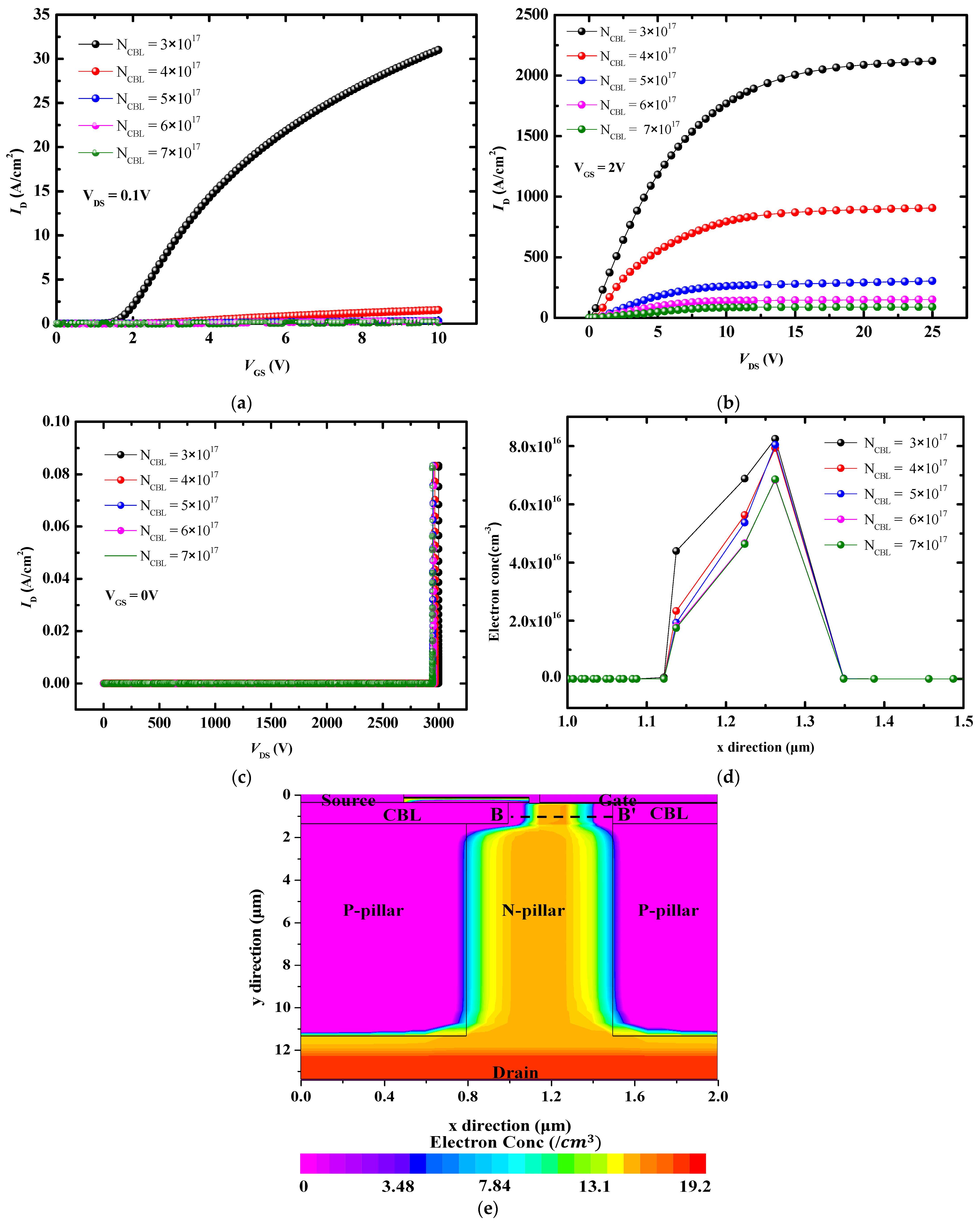
3.1. Static Performance Based on CBL Doping Concentration

The impact of the CBL doping concentration (NCBL) on AlGaN/GaN CAVETs with double SJ was studied. As shown in Figure 5a,b, the drain current decreased as the NCBL increased within the range of 3 × 10 17 to 7 × 10 17 cm−3 [23]. This reduction was attributed to the formation of a wider depletion region between the CBL and n-pillar regions at higher NCBL levels, which narrowed the current path. When NCBL exceeded 3 × 10 17 cm−3, the drain current density was significantly reduced, whereas the on-resistance continued to increase. Therefore, NCBL = 3 × 10 17 cm−3 was adopted [24].
Figure 5c shows that the off-state breakdown voltage decreased as the NCBL increased due to a trade-off [25]. The threshold voltages calculated at Vd = 0.1 V were 1.69, 2.52, 2.92, 3.12, and 3.23 V. This indicates that the electron concentration beneath the gate decreased with increasing NCBL, as shown in Figure 5d. This decrease can be attributed to the widening of the depletion region between the gate CBL and the n-pillar region as the NCBL increased. Figure 5e shows the cutline for the electron concentration in the device structure [26].

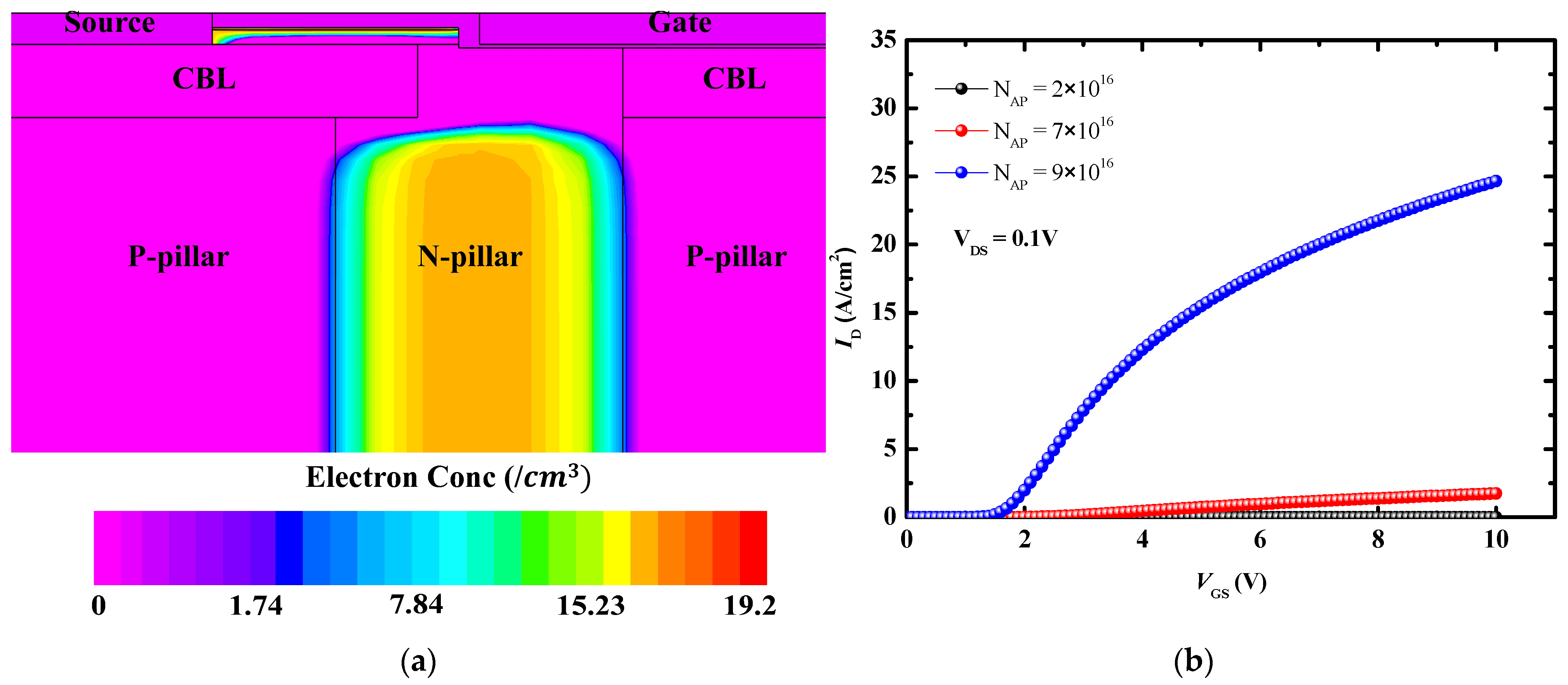
3.2. Static Performance Based on Aperture Length

The impact of aperture length (LA) on AlGaN/GaN CAVETs with double SJ was studied. Figure 6a shows the transfer curve based on LA ranging from 0.5 to 0.9 μm. As shown in Figure 6a,b, devices with a longer LA exhibited higher drain currents due to a wider current path, which was attributed to an improved current chocking effect [20]. The normally-off operation was achieved in a double SJ device, where the threshold voltage (Vth) was varied between 1.58 V and 1.65 V for the simulated LA. Figure 6c shows that devices with a longer LA exhibited lower off-state breakdown voltages [26]. A longer LA cannot fully deplete the drift region, resulting in an uneven electric-field distribution. In essence, the region under the CBL layers is not shielded from high drain voltage, resulting in a low breakdown voltage [25]. The formation of a new depletion region laterally between the p-pillar and n-pillar regions due to the additional SJ beneath the gate CBL led to a more uniform electric-field distribution, as shown in Figure 6d. Therefore, a compromise can be made between the breakdown voltage and the drain current [23].

3.3. Optimization of AlGaN/GaN CAVET with Double Superjunction

In this study, the LA and NCBL were identified as critical design parameters. Figure 7a,b compares the double SJ and single SJ structures. As shown in Figure 7a, the gate bias was fixed at 4 V, and an increase in the drain voltage resulted in a slight increase in resistance, indicating a trade-off between the breakdown voltage (BV) and the resistance [23]. As shown in Figure 7b, the double SJ structure exhibited enhanced BV, which can be attributed to the addition of a p-pillar beneath the gate [20].
The optimal device performance for the AlGaN/GaN CAVET with double SJ was achieved with an LA/NCBL ratio of 0.7 μm/3 × 1017 cm−3 [17], balancing the forward conduction and off-state breakdown voltage. This device delivered a BV of 2933 V and RON-SP of 1.29 mΩ·cm−2, yielding a BFOM of 6.66 GW·cm−2. Similarly, the optimal AlGaN/GaN CAVET with a single SJ was also obtained with the same LA/NCBL ratio of 0.7 μm/3 × 1017 cm−3, delivering a BV of 2786 V and RON-SP of 1.17 mΩ·cm−2. In the single SJ CAVET, the peak electric field occurred at the p-n junction between the gate CBL and the n-pillar, as shown in Figure 7c [26]. In the double SJ device, the additional SJ beneath the gate CBL enhanced the device’s BV by leading to a more uniform electric field distribution under the gate CBL layer; however, it resulted in a 9.69% increase in the on-resistance. The AlGaN/GaN CAVET with double CBLs achieved a BV of 2580 V and RON-SP of 1.188 mΩ·cm−2 with an aperture length of 0.7 μm. As shown in Figure 7c, the highest breakdown voltage was achieved in the AlGaN/GaN CAVET with double SJ.
Compared to the previous AlGaN/GaN CAVET structures, the CAVET with double SJ in this work exhibited excellent device performance with the best BFOM. The source field plate CAVET (SFP-CAVET), stepped doping microstructure trench CAVET (SDS-Trench CAVET), and the proposed CAVET with SJ, exhibited higher BV and improved BFOM compared to EBP-CAVET and DCAVET structures without SJ. Among the CAVET with SJ, even if the proposed structure features a thin drift layer thickness of 10 μm, it demonstrates superior BV. Table 3 provides a comparison of the performance parameters with the reported CAVETs. In addition, the CAVETs with double SJ exhibited an improved drain current density compared to the single SJ device.
The transfer capacitance (Crss) characteristics are shown in Figure 8. The Crss was obtained via simulations using an AC signal at 1 MHz for the AlGaN/GaN CAVET with double SJ. As the drain voltage increased, Crss decreased because of the expansion of the depletion region [7]. The Qrss measured 2.145 pC, which was lower than that of devices with single SJ and without SJ [18], as shown in Figure 8. The Crss for the CAVET was dependent on the gate length and the gate CBL length because the gate–drain overlap area is determined by them. The gate CBL effectively reduced the Crss by screening the gate from the drain bias [29]. Crss could be decreased by placing the additional p-pillar under the gate CBL in the device with double SJ by widening of the lateral depletion region.

4. Conclusions

This study proposes a normally-off AlGaN/GaN vertical CAVET with double SJ to improve device breakdown voltage and investigates its electrical characteristics via TCAD simulation. An additional p-pillar layer was formed beneath the gate CBL to enhance the reverse blocking capability while maintaining strong forward conduction. Although the BFOM of the proposed device was similar to that of the device with a single SJ, an enhancement in the breakdown voltage was achieved, which was attributed to a more uniform electric field distribution beneath the CBL layers. In the AlGaN/GaN CAVET with a single SJ, a BV of 2786 V and RON-SP of 1.17 mΩ·cm−2 were achieved, whereas the AlGaN/GaN CAVET with a double SJ achieved a BV of 2933 V and RON-SP of 1.29 mΩ·cm−2. Also, the device with double SJ exhibited an improved drain current density compared to the single SJ device. Compared to the previous AlGaN/GaN CAVET structures, CAVET with double SJ in this work exhibits excellent device performance with the best BFOM. Among the CAVET with SJ, even if the proposed structure features a thin drift layer thickness to 10 μm, it demonstrates superior BV and lower RON-SP.
In addition, the reduced Crss indicates a faster switching potential. The proposed device achieved a lower figure of merit (RON-SP × Qrss) of 2.77 × 10⁻¹⁵ C·Ω·cm−2 than the 2.99 × 10⁻¹⁵ C·Ω·cm−2 achieved by the value for the single SJ device [19]. These simulation results demonstrate the potential of double SJ CAVETs in high-power electronics and provide a promising path for the further development of GaN-based CAVETs with SJs.

Author Contributions

Conceptualization, J.-U.K. and S.-H.H.; investigation, J.-U.K. and D.-Y.P.; data curation, J.-U.K.; writing—original draft preparation, J.-U.K. and D.-Y.P.; writing—review and editing, B.-J.P. and S.-H.H.; visualization, J.-U.K.; All authors have read and agreed to the published version of the manuscript.

Funding

This research was funded by the BK21 Four Project funded by the Ministry of Education, Korea (No. 4199990113966).

Institutional Review Board Statement

Not applicable.

Informed Consent Statement

Not applicable.

Data Availability Statement

Additional data are available upon reasonable request.

Conflicts of Interest

The authors declare no conflicts of interest.

References

  1. Buffolo, M.; Bai, P.; Zhang, Y.; Otake, H.; Egami, S.; Ohta, H.; Nanishi, Y.; Takasu, H. Review and Outlook on GaN and SiC Power Devices: Industrial State-of-the-Art, Applications, and Perspectives. IEEE Trans. Electron Devices 2024, 71, 1334–1355. [Google Scholar] [CrossRef]
  2. Bai, P.; Zhang, Y.; Otake, H.; Egami, S.; Ohta, H.; Nanishi, Y.; Takasu, H. A Novel Trench-Gated Vertical GaN Transistor With Dual-Current-Aperture by Electric-Field Engineering for High Breakdown Voltage. IEEE Trans. Electron Devices 2022, 69, 1219–1225. [Google Scholar] [CrossRef]
  3. Zhang, Y.; Otake, H.; Egami, S.; Ohta, H.; Nanishi, Y.; Takasu, H. Electrothermal Simulation and Thermal Performance Study of GaN Vertical and Lateral Power Transistors. IEEE Trans. Electron Devices 2013, 60, 2224–2230. [Google Scholar] [CrossRef]
  4. Otake, H.; Egami, S.; Ohta, H.; Nanishi, Y.; Takasu, H. GaN-Based Trench Gate Metal Oxide Semiconductor Field Effect Transistors with Over 100 cm2/(V·s) Channel Mobility. Jpn. J. Appl. Phys. 2007, 46, L599. [Google Scholar] [CrossRef]
  5. He, W.; Li, J.; Liao, Z.; Lin, F.; Wu, J.; Wang, B.; Wang, M.; Liu, N.; Chiu, H.-C.; Kuo, H.-C. 1.3 kV Vertical GaN-Based Trench MOSFETs on 4-Inch Free Standing GaN Wafer. Nanoscale Res. Lett. 2022, 17, 14. [Google Scholar] [CrossRef]
  6. Ben-Yaacov, I.; Seck, Y.-K.; Mishra, U.K.; DenBaars, S.P. AlGaN/GaN Current Aperture Vertical Electron Transistors with Re-Grown Channels. J. Appl. Phys. 2004, 95, 2073–2078. [Google Scholar] [CrossRef]
  7. Ji, D.; Zhang, Y.; Li, Y.; Li, M.; Liu, X.; Zhang, Q.; Li, X. Dynamic Modeling and Power Loss Analysis of High-Frequency Power Switches Based on GaN CAVET. IEEE Trans. Electron Devices 2016, 63, 4011–4017. [Google Scholar] [CrossRef]
  8. Shibata, D.; Kajitani, R.; Ogawa, M.; Tanaka, K.; Tamura, S.; Hatsuda, T.; Ishida, M.; Ueda, T. 1.7 kV/1.0 mΩ·cm2 Normally-Off Vertical GaN Transistor on GaN Substrate with Regrown p-GaN/AlGaN/GaN Semipolar Gate Structure. In Proceedings of the 2016 IEEE International Electron Devices Meeting (IEDM), San Francisco, CA, USA, 3–7 December 2016; pp. 248–251. [Google Scholar]
  9. Luo, C.; Zhang, Y.; Li, Y.; Zhao, X.; Hu, H. Novel High-Voltage GaN CAVET with High Threshold Voltage and Low Reverse Conduction Loss. Microelectron. J. 2024, 148, 106195. [Google Scholar] [CrossRef]
  10. Mishra, U.K.; Zhang, Y.; Ambacher, O.; Gossmann, H.-J.; Schaff, W. AlGaN/GaN HEMTs—An Overview of Device Operation and Applications. Proc. IEEE 2002, 90, 1022–1031. [Google Scholar] [CrossRef]
  11. Ji, D.; Laurent, M.A.; Agarwal, A.; Li, W.; Mandal, S.; Keller, S.; Chowdhury, S. Normally OFF Trench CAVET With Active Mg-Doped GaN as Current Blocking Layer. IEEE Trans. Electron Devices 2017, 64, 805–812. [Google Scholar] [CrossRef]
  12. Ambacher, O.; Albrecht, M.; Lischka, K.; Stutzmann, M.; Muller, G.; Zollner, S.; Tietjen, S.; Badra, K.; Hillebrand, R. Two-Dimensional Electron Gases Induced by Spontaneous and Piezoelectric Polarization Charges in N- and Ga-Face AlGaN/GaN Heterostructures. J. Appl. Phys. 1999, 85, 3222–3233. [Google Scholar] [CrossRef]
  13. Ma, Y.; Xiao, M.; Du, Z.; Wang, L.; Carlson, E.; Guido, L.; Wang, H.; Wang, L.; Luo, Y.; Zhang, Y. Activating Thick Buried p-GaN for Device Applications. IEEE Trans. Electron Devices 2022, 69, 4224–4230. [Google Scholar] [CrossRef]
  14. Kachi, T.; Hirukawa, K.; Narita, T.; Sakurai, H.; Sumida, K.; Matys, M.; Horita, M.; Kataoka, K.; Ikarashi, N.; Sierakowski, K.; et al. Process Engineering of GaN Power Devices via Selective-Area p-Type Doping with Ion Implantation and Ultra-High-Pressure Annealing. J. Appl. Phys. 2022, 132, 130901. [Google Scholar] [CrossRef]
  15. Silvaco Inc. ATLAS User’s Manual; Silvaco Inc.: Santa Clara, CA, USA, 2019. [Google Scholar]
  16. Liu, T.; Hu, S.; Wang, J.; Guo, G.; Luo, J.; Wang, Y.; Guo, J.; Huo, Y. An Investigation of Electric Field and Breakdown Voltage Models for a Deep Trench Superjunction SiC VDMOS. IEEE Access 2019, 7, 132087–132097. [Google Scholar] [CrossRef]
  17. Kang, H.; Udrea, F. On the Specific On-State Resistance of Superjunction MOSFETs with a Compensated Pillar. IEEE Electron Device Lett. 2018, 39, 1746–1749. [Google Scholar] [CrossRef]
  18. Chu, R.; Zhang, X.; Zhang, Y.; Yao, H.; Chen, X.; Fu, X. 1200-V Normally Off GaN-on-Si Field-Effect Transistors with Low Dynamic On-Resistance. IEEE Electron Device Lett. 2011, 32, 632–634. [Google Scholar]
  19. Mishra, U.K.; Sukhdeo, N.; Shur, M.S.; Tang, J.; Xie, H. GaN-Based RF Power Devices and Amplifiers. Proc. IEEE 2008, 96, 287–305. [Google Scholar] [CrossRef]
  20. Ma, J.; Guo, Z.; Sun, H.; Li, Y.; Zhang, M.; Xia, X.; Xia, F.; Tan, X.; Huang, Z.; Ding, X.; et al. Study of GaN-Based Superjunction CAVET with Dipole Layer to Further Improve On-Resistance and Breakdown Voltage. J. Electron. Mater. 2022, 51, 110–118. [Google Scholar] [CrossRef]
  21. Mao, W.; Wang, H.; Shi, P.; Yang, C.; Zhang, Y.; Zheng, X.; Wang, C.; Zhang, J.; Hao, Y. Study of GaN-based Step-Doping Superjunction CAVET for Further Improvement of Breakdown Voltage and Specific On-Resistance. Semicond. Sci. Technol. 2018, 33, 025005. [Google Scholar] [CrossRef]
  22. Uren, M.J.; Hill, A.D.; Mohammadi, A.; Hafez, N. Punch-Through in High Voltage AlGaN/GaN HEMTs: The Role of Buffer Design. IEEE Trans. Electron Devices 2017, 64, 2826–2832. [Google Scholar] [CrossRef]
  23. Bahat-Treidel, E.; Hilt, O.; Brunner, F.; Wurfl, J.; Trankle, G. Punchthrough-Voltage Enhancement of AlGaN/GaN HEMTs Using AlGaN Double-Heterojunction Confinement. IEEE Trans. Electron Devices 2008, 55, 3354–3359. [Google Scholar] [CrossRef]
  24. Ueda, T. GaN Power Devices: Current Status and Future Challenges. Jpn. J. Appl. Phys. 2019, 58, SC0804. [Google Scholar] [CrossRef]
  25. Kozak, J.P.; Zhang, R.; Porter, M.; Song, Q.; Liu, J.; Wang, B.; Wang, R.; Saito, W.; Zhang, Y. Stability, Reliability, and Robustness of GaN Power Devices: A Review. IEEE Trans. Power Electron. 2023, 38, 1234–1245. [Google Scholar] [CrossRef]
  26. Xiao, M.; Zhang, R.; Dong, D.; Wang, H.; Zhang, Y. Design and Simulation of GaN Superjunction Transistors With 2-DEG Channels and Fin Channels. IEEE J. Emerg. Sel. Top. Power Electron. 2019, 7, 1475–1485. [Google Scholar] [CrossRef]
  27. Wang, H.; Zhang, Y.; Li, Z.; Xu, J.; Zhang, Q.; Wu, Z. Study of High Breakdown Voltage GaN-Based Current-Aperture Vertical Electron Transistor with Source-Connected Field-plates for Power Applications. Semicond. Sci. Technol. 2018, 33, 075008. [Google Scholar] [CrossRef]
  28. Li, Y.; Xu, L.; Guo, Z.; Sun, H. Study of High-Performance GaN-Based Trench CAVET with Stepped Doping Microstructure. Micromachines 2022, 13, 1273. [Google Scholar] [CrossRef]
  29. Wei, J.; Wang, Y.; Zhang, M.; Jiang, H.; Chen, K.J. High-Speed Power MOSFET with Low Reverse Transfer Capacitance Using a Trench/Planar Gate Architecture. In Proceedings of the 2017, 29th International Symposium on Power Semiconductor Devices and IC’s (ISPSD), Sapporo, Japan, 28 May–1 June 2017; pp. 12–15. [Google Scholar]
Figure 1. Schematic cross-section of the proposed normally-off vertical AlGaN/GaN CAVET (a) with double SJ (b) with single SJ, and (c) without SJ.
Technologies 12 00262 g001
Figure 2. Total current density at VGS = 10 V and VDS = 0.1 V (a) AlGaN/GaN CAVET with double SJ (b) AlGaN/GaN CAVET with single SJ, and (c) AlGaN/GaN CAVET without SJ.
Technologies 12 00262 g002
Figure 3. (a) Electron concentration at aperture doping of 2 × 10 16 cm−3 (b) Id-Vgs characteristic depending on the doping concentration of the aperture.
Technologies 12 00262 g003
Figure 4. Simulated contours at breakdown voltage: (a) impact generation rate (i.e., impact ionization), (b) electron current density, (c) hole current density, and (d) electric field distribution.
Technologies 12 00262 g004
Figure 5. The CBL doping concentration range of 3 × 10¹⁷ to 7 × 1017 cm−3: (a) transfer curve, (b) output curve, (c) breakdown voltage, (d) electron concentration beneath the gate, and (e) aperture layer cutline for the electron concentration in the device structure.
Technologies 12 00262 g005
Figure 6. Electrical characteristics depending on aperture length: (a) transfer curve, (b) output curve, (c) breakdown voltage, and (d) electric field distribution at a drain voltage of 1200 V.
Technologies 12 00262 g006
Figure 7. Comparison of AlGaN/GaN CAVET with single and double SJ: (a) Id-Vds characteristic, (b) breakdown voltage, and (c) electric field at a drain voltage of 1200 V.
Technologies 12 00262 g007
Figure 8. Reverse transfer capacitances of characteristics (Crss) of AlGaN/GaN CAVET without an SJ, with a single SJ, and with a double SJ at Vgs = 0 V.
Technologies 12 00262 g008
Table 1. Key device parameters set in the simulation.
SymbolStatementValue
WCellCell pitch2 μm
tCBLCBL thickness1 μm
tDriftThickness of drift layer10 μm
LAAperture length0.7 μm
LCBLCBL length0.3 μm
t(AlGaN/GaN)AlGaN/GaN thickness30/200 nm
LPp-pillar length0.8 μm
NUUID GaN doping concentration 1 × 10 16 cm−3
NPp-pillar GaN doping concentration 1 × 10 16 cm−3
NNn-pillar GaN doping concentration 2 × 10 16 cm−3
NCBLCBL doping concentration 3 × 10 17 cm−3
NAPAperture GaN doping concentration 9 × 10 16 cm−3
Table 2. AlGaN/GaN model parameters used in simulation [15].
MaterialStatementValue
GaNElectron mobility1200 cm2/V∙s
Hole mobility10 cm2/V∙s
Lifetime of electron 1 × 10 9 s
Lifetime of hole 1 × 10 9 s
Saturation velocity 2 × 10 17 cm/s
AlGaNElectron mobility600 cm2/V∙s
Hole mobility10 cm2/V∙s
Lifetime of electron 1 × 10 8 s
Lifetime of hole 1 × 10 8 s
Table 3. A comparison of the performance characteristics vertical AlGaN/GaN CAVET.
DeviceSuper-JunctionDrift Layer Thickness
[μm]
Breakdown Voltage [V]Specific on Resistance [mΩ·cm−2]BFOM
[GW·cm−2]
Reference
EBP-CAVETX716601.192.32[9]
DCAVETX615040.772.94[2]
SFP-CAVETO1536102.255.97[27]
SDS-CAVETO1525231.344.77[28]
CAVET w/DSJO1029331.296.66this work
Disclaimer/Publisher’s Note: The statements, opinions and data contained in all publications are solely those of the individual author(s) and contributor(s) and not of MDPI and/or the editor(s). MDPI and/or the editor(s) disclaim responsibility for any injury to people or property resulting from any ideas, methods, instructions or products referred to in the content.

