Communication

FPGA-Based Implementation of a New 3-D Multistable Chaotic Jerk System with Two Unstable Balance Points

by
Sundarapandian Vaidyanathan
1,
Esteban Tlelo-Cuautle
2,*,
Khaled Benkouider
3,
Aceng Sambas
4,5 and
Brisbane Ovilla-Martínez
6
1
Centre for Control Systems, Vel Tech University, Vel Nagar, Avadi, Chennai 600 062, Tamil Nadu, India
2
Department of Electronics, INAOE, Mexico City 72840, Mexico
3
Non Destructive Testing Laboratory, Automatic Department, Jijel University, BP 98, Jijel 18000, Algeria
4
Faculty of Informatics and Computing, Universiti Sultan Zainal Abidin, Gong Badak 21300, Terengganu, Malaysia
5
Department of Mechanical Engineering, Universitas Muhammadiyah Tasikmalaya, Tasikmalaya 46196, West Java, Indonesia
6
Department of Computer Science, Cinvestav-IPN, Mexico City 07360, Mexico
*
Author to whom correspondence should be addressed.
Technologies 2023, 11(4), 92; https://doi.org/10.3390/technologies11040092
Submission received: 2 May 2023 / Revised: 29 June 2023 / Accepted: 5 July 2023 / Published: 11 July 2023
(This article belongs to the Collection Electrical Technologies)

Abstract

:
Mechanical jerk systems have applications in several areas, such as oscillators, microcontrollers, circuits, memristors, encryption, etc. This research manuscript reports a new 3-D chaotic jerk system with two unstable balance points. It is shown that the proposed mechanical jerk system exhibits multistability with coexisting chaotic attractors for the same set of system constants but for different initial states. A bifurcation analysis of the proposed mechanical jerk system is presented to highlight the special properties of the system with respect to the variation of system constants. A field-programmable gate array (FPGA) implementation of the proposed mechanical jerk system is given by synthesizing the discrete equations that are obtained by applying one-step numerical methods. The hardware resources are reduced by performing pipeline operations, and, finally, the paper concludes that the experimental results of the proposed mechanical jerk system using FPGA-based design show good agreement with the MATLAB simulations of the same system.

1. Introduction

Mechanical dynamical systems have several applications in chaos theory [1,2,3,4]. For instance, Reis and Savi [1] studied quasi-periodic and spatiotemporal chaotic responses in a conservative Duffing-type mechanical system with cubic nonlinearity. Using Lyapunov stability theory and power spectrum analysis, Cai et al. [2] studied the periodic motion and chaos in the dynamics of a van der Pol (VDP) oscillator. Madiot et al. [3] demonstrated dissipative chaotic motion in an electromechanical resonator. Balamurali et al. [4] investigated the generation of multi-scroll chaos in coupled Rayleigh–Duffing oscillators. Other related investigations can be found in recent papers, which in addition, include the hardware implementation of the chaotic systems. It is apparent that one of the most used devices to verify experimental chaotic attractors is the field-programmable gate array (FPGA). For example, the authors of [5] present the FPGA implementation of an audio block encryption using a 3-D chaotic system with adaptive parameter perturbation, showing that their proposed scheme is suitable for real-time secure communication. An FPGA implementation of an autonomous Josephson junction jerk oscillator and the investigated coexisting and chaotic attractors, is given in [6], where the authors also show the control and synchronization of the chaotic oscillator. FPGAs have also been used to implement memory-based systems, as shown in [7], where the authors show an encryption application and FPGA realization of a fractional memristive chaotic system. More elaborated applications can also be found in recent works, such as that described in [8], in which the design, hardware implementation and performance analysis of three chaos-based stream ciphers using FPGAs are presented. This study also emphasizes the generation of robust pseudo-random number generators of chaotic sequences and their corresponding stream ciphers. The authors of [9] have also recently described the FPGA implementation of an image encryption-steganography system using a novel chaotic system with line equilibria to enhance security.
The main focus of this paper is on the implementation of a new 3-D multistable chaotic jerk system with two unstable balance points. It is highlighted that the main contribution reported herein is not only in the introduction of a new 3-D mathematical model, but also the FPGA implementation of a new 3-D multistable chaotic jerk system with low hardware resources, which is compared with a direct implementation from the mathematical description and using pipeline operations.
Regarding 3-D chaotic jerk systems, it is well-known that, in classical mechanics, an autonomous jerk differential equation has the general form given in (1), where “jerk” refers to the third-order derivative ϵ = d 3 ϵ d t 3 .
ϵ = F ( ϵ , ϵ ˙ , ϵ ¨ ) ,
To represent the jerk system in a set of 3-D equations, (1) presents a system of ordinary differential equations (ODE), for which one can use the phase variables given in (2), so that one can rewrite the jerk differential equations as described by (3), where F ( x , y , z ) represents the nonlinear dynamics that the system uses to drive different chaotic behaviors.
x = ϵ , y = ϵ ˙ , z = ϵ ¨
x ˙ = y y ˙ = z z ˙ = F ( x , y , z )
Many chaotic jerk systems have been reported in the literature [10,11,12,13,14]. Sprott [10] described a simple dissipative chaotic jerk system with one quadratic nonlinearity. Sun and Sprott [11] presented a dissipative chaotic jerk system with piecewise exponential nonlinearity. Liu et al. [12] discussed a new dissipative chaotic jerk system having two quadratic nonlinearities. Vaidyanathan et al. [13] proposed a new dissipative chaotic jerk system having two exponential nonlinearities and presented its electronic circuit simulation. Rajagopal et al. [14] proposed a new dissipative chaotic jerk system with two quadratic nonlinearities, discussed its dynamic properties, and provided a circuit realization of the new jerk system. Chaotic jerk systems have applications in many areas, such as oscillators [3,15], microcontrollers [16], circuits [17,18], memristors [19,20], encryption [21], etc.
This research manuscript presents a new 3-D chaotic jerk system with three quadratic nonlinearities. Dynamic analysis of a chaotic system, such as of the dissipativity, symmetry, Kaplan–Yorke dimension and stability of the equilibrium points, is very useful for understanding the qualitative properties of the system [22]. We show that the new jerk system has two unstable equilibrium points. Hence, the new jerk system represents a self-excited attractor in the chaotic case. We also demonstrate that the proposed mechanical jerk system can exhibit multistability with coexisting chaotic attractors. In fact, multistability is a special property of nonlinear dynamical systems, which refers to the coexistence of periodic orbits or chaotic attractors for the same set of system constants but considering different initial conditions or states [20,21].
Bifurcation analysis of chaotic dynamical systems is a powerful tool to verify chaotic motion, and is very useful to understand the qualitative properties of the systems, such as the existence of equilibrium points, quasi-periodic motion, periodic motion and chaotic attractors [23,24]. A bifurcation analysis of the proposed mechanical jerk system is presented herein to describe the special properties of the system with respect to the variation of the system constants.
Complete synchronization of chaotic systems has several applications, such as secure communications [25,26,27]. Using backstepping control, we achieve complete synchronization of a pair of new chaotic jerk systems considered as master and slave systems for communication. The synchronization results for the new chaotic jerk system with a stable equilibrium are detailed in Section 5.
Finally, the proposed chaotic jerk system is implemented with embedded hardware using an FPGA and fixed-point notation to perform the computer arithmetic, as undertaken in the majority of related works, and as already demonstrated in [28]. It is also worth mentioning that the new 3-D chaotic system can be designed using integrated circuit technology, as performed for fractional-order systems in [29]; however, this work makes use of the advantages of FPGAs for the fast verification and prototyping of systems. The main focus of this paper is on the implementation of a new 3-D multistable chaotic jerk system with two unstable balance points. It is highlighted that the main contribution reported herein is not only the introduction of a new 3-D mathematical model, but also the FPGA implementation with low hardware resources, which is compared with a direct implementation from the mathematical description, so that the hardware resources are reduced by using pipeline operations to reduce the number of multiplication blocks, compared to a direct FPGA implementation of the discretized equations.
The main contributions of our research work can be enumerated as follows:
(1)
We propose a new dissipative chaotic jerk system having three quadratic nonlinear terms.
(2)
We establish that the new chaotic jerk system has two unstable equilibrium points, which implies that the new system exhibits a self-excited chaotic attractor.
(3)
We carry out a detailed bifurcation analysis of the new jerk system which shows the changes in the dynamic behavior of the jerk system with respect to changes in the system parameters.
(4)
We establish that the new jerk system has multistability with coexisting chaotic attractors.
(5)
We provide a control application of the new jerk system, viz. complete synchronization of the new jerk systems via backstepping control.
(6)
We design an FPGA implementation of the new chaotic jerk system.
Section 2 describes the mathematical model of the new jerk system. Section 3 describes the bifurcation analysis and the behaviors when varying the parameters of the mathematical model. The multistability analysis and the coexistence of chaotic attractors is shown in Section 4. The complete synchronization of the new jerk systems via backstepping control method is discussed in Section 5. The FPGA implementation and the experimental results are given in Section 6. Finally, the conclusions are summarized in Section 7.

2. A New 3-D Jerk System

We consider a new 3-D jerk system implied by the dynamics modeled in a compact form, as denoted in (4), where the three state variables can be described by Z = ( x , y , z ) . We make an assumption that a , b and c are constant parameters taking only positive values. The three nonlinearities are given by x y c x 2 + y 2 , which require four two-input multipliers; however, an appropriate factorization of the nonlinear functions can lead us to reduce the number of multiplication blocks, as shown in Section 5.
x ˙ = y y ˙ = z z ˙ = a x b z x y c x 2 + y 2
We shall display the chaotic properties of the new 3-D jerk system (4) by considering the parameters as ( a , b , c ) = ( 1 , 1 , 0.1 ) . For simulations, we take an initial state as Z ( 0 ) = ( 0.3 , 0.2 , 0.3 ) . Using MATLAB, the Lyapunov exponent index (LEI) values of the jerk system (4) are evaluated as
τ 1 = 0.1176 , τ 2 = 0 , τ 3 = 1.1176
The Kaplan–Yorke fractal dimension of the jerk system (4) is obtained as follows:
D K Y = 2 + τ 1 + τ 2 | τ 3 | = 2.1052
In (5), it is observed that the LEI values have the signs ( + , 0 , ) , which shows that the jerk system (4) is chaotic. Furthermore, we note that
τ 1 + τ 2 + τ 3 = 1 < 0
This calculation establishes that the mechanical jerk system (4) is dissipative. The dissipativity of the jerk system (4) can also be seen by calculating the divergence of the vector field
F ( x , y , z ) = y , z , a x b z x y c x 2 + y 2
We note that the divergence of the vector field F is computed as
div F = F 1 x + F 2 y + F 3 z = b = 1 < 0
Since the divergence of the vector field of the jerk system (4) is negative, we have shown that the jerk system (4) is a dissipative system.
Thus, we have shown that the new jerk system (4) is both chaotic and dissipative for the parameter values ( a , b , c ) = ( 1 , 1 , 0.1 ) .
The exponential contraction rate for the jerk system (4) is computed as follows:
d V d t = ( div F ) V = V
Thus, it follows that
V ( t ) = V 0 e t
where each volume containing the system trajectory of the jerk system (4) shrinks to zero as t at an exponential rate of t . Thus, the system orbits of the jerk system (4) are ultimately confined into a specific limit set of zero volume, and the asymptotic motion settles onto a chaotic attractor. Thus, we have established the existence of the chaotic attractor for the jerk system (4).
The balance points or equilibrium points of the jerk system (4) are obtained by solving the equations x ˙ = y ˙ = z ˙ = 0 .
To calculate the balance points of the jerk system (4), we solve the following equations:
  y = 0
  z = 0
a x b z x y c x 2 + y 2 = 0
Solving the system (12), we obtain the solutions as
y = 0 , z = 0 , x ( c x + a ) = 0
Since the parameters a , b , c are taken as positive constants, we obtain two balance points as
B 0 = ( 0 , 0 , 0 ) , B 1 = ( a / c , 0 , 0 )
For the chaotic case, when ( a , b , c ) = ( 1 , 1 , 0.1 ) , the balance points are numerically obtained as follows:
B 0 = ( 0 , 0 , 0 ) , B 1 = ( 10 , 0 , 0 )
The Jacobian matrix of the jerk system (4) at B 0 = ( 0 , 0 , 0 ) is obtained as follows:
J 0 = 0 1 0 0 0 1 1 0 1
The Jacobian matrix J 0 has the eigenvalues 1.4656 , 0.2328 ± 0.7926 i . This shows that the equilibrium point B 0 = ( 0 , 0 , 0 ) is a saddle-focus point, which is unstable.
The Jacobian matrix of the jerk system (4) at B 1 = ( 10 , 0 , 0 ) is obtained as follows:
J 1 = 0 1 0 0 0 1 1 10 1
The Jacobian matrix J 1 has the eigenvalues 3.6586 , 0.0991 and 2.7577 . This shows that the equilibrium point B 1 = ( 10 , 0 , 0 ) is a saddle point, which is unstable.
Hence, the jerk system (4) depicts a self-excited attractor in the chaotic case.
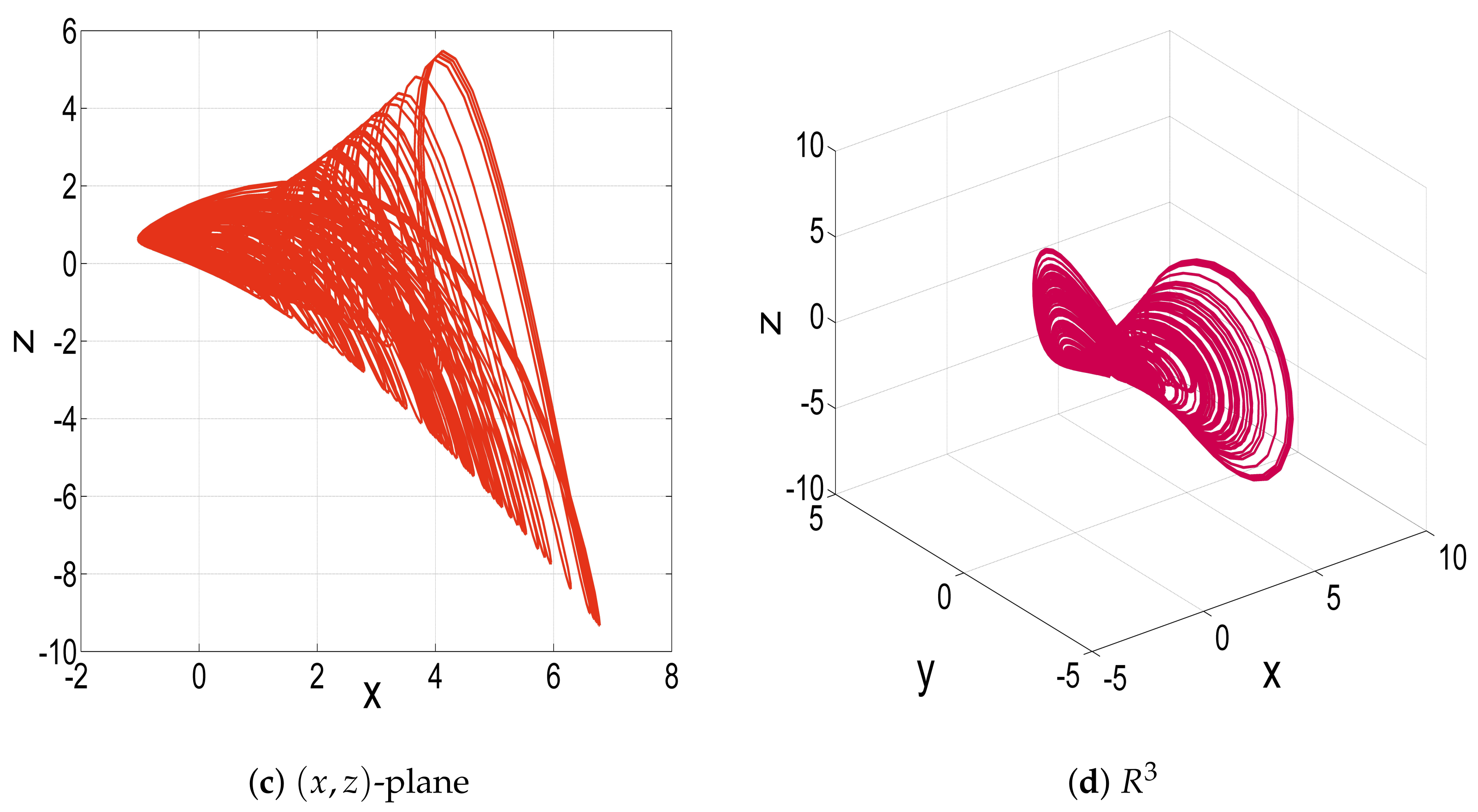
Figure 1 illustrates the MATLAB plots for the jerk system (4) corresponding to the parameter data ( a , b , c ) = ( 1 , 1 , 0.1 ) , with initial conditions Z ( 0 ) = ( 0.3 , 0.1 , 0.3 ) .

3. Bifurcation Analysis for the New 3-D Jerk System

We perform a bifurcation analysis to evaluate the dynamical properties of the jerk system (4) using Lyapunov exponent (LE) spectrums, bifurcation diagrams and phase plots for the initial states Z 0 = ( 0.3 , 0.2 , 0.3 ) .

3.1. When the Parameter a Varies

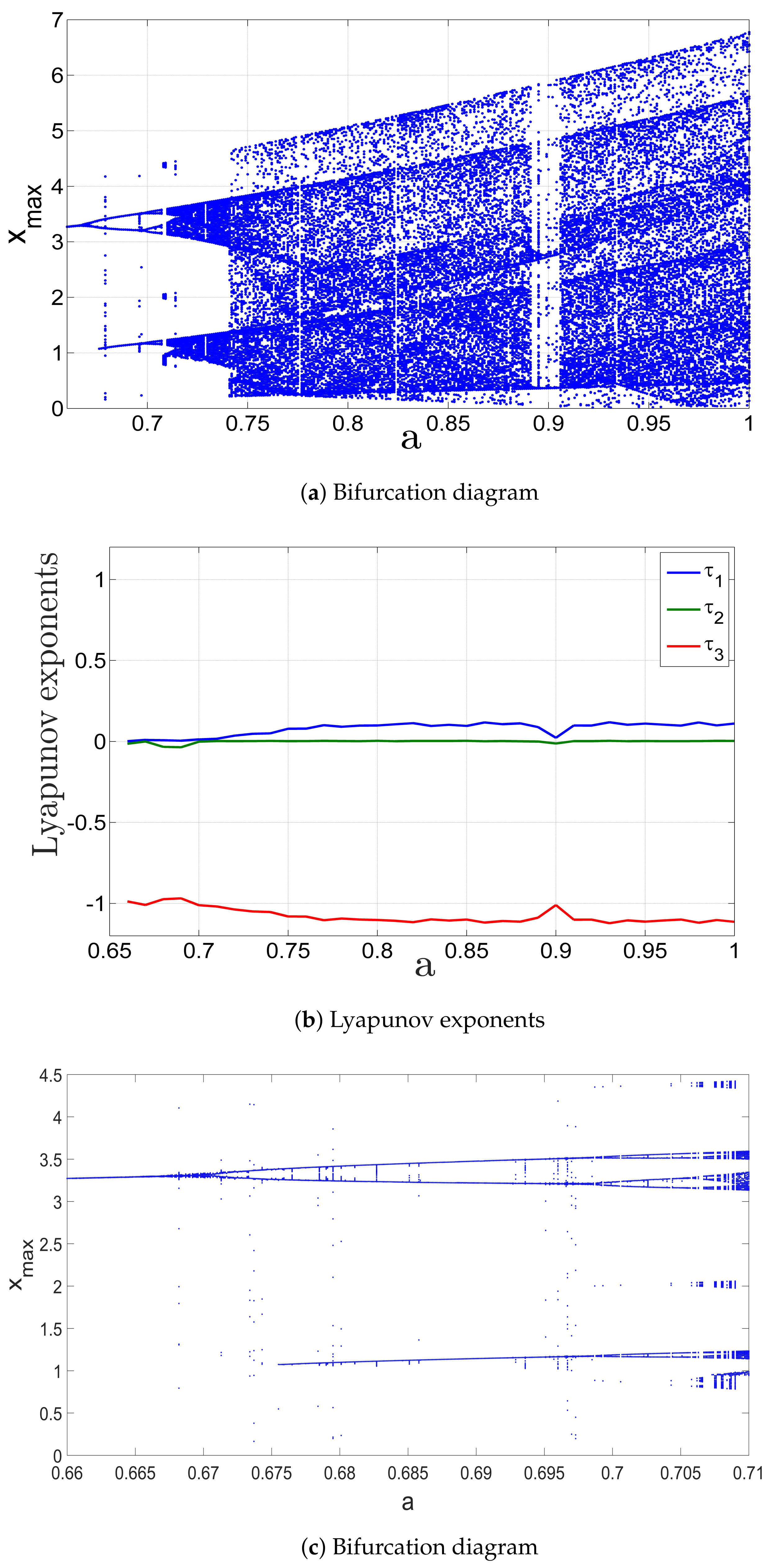
In this subsection, we fix the values of the parameters b and c, as b = 1 and c = 0.1 . We allow the parameter a to vary in the interval [ 0.65 , 1 ] . Then, we analyze the corresponding dynamical behavior of the jerk system (4) using Lyapunov exponents (LEs), as shown in Figure 2b and the bifurcation diagram depicted in Figure 2a. Additionally, Figure 2c provides a zoomed-in view of the bifurcation diagram, specifically focusing on the region where period-doubling occurs. From the above-mentioned figures, it is evident that the jerk system (4) follows the well-known period-doubling route at the beginning of the parameter a interval, eventually transitioning into a chaotic region for the rest of the interval.
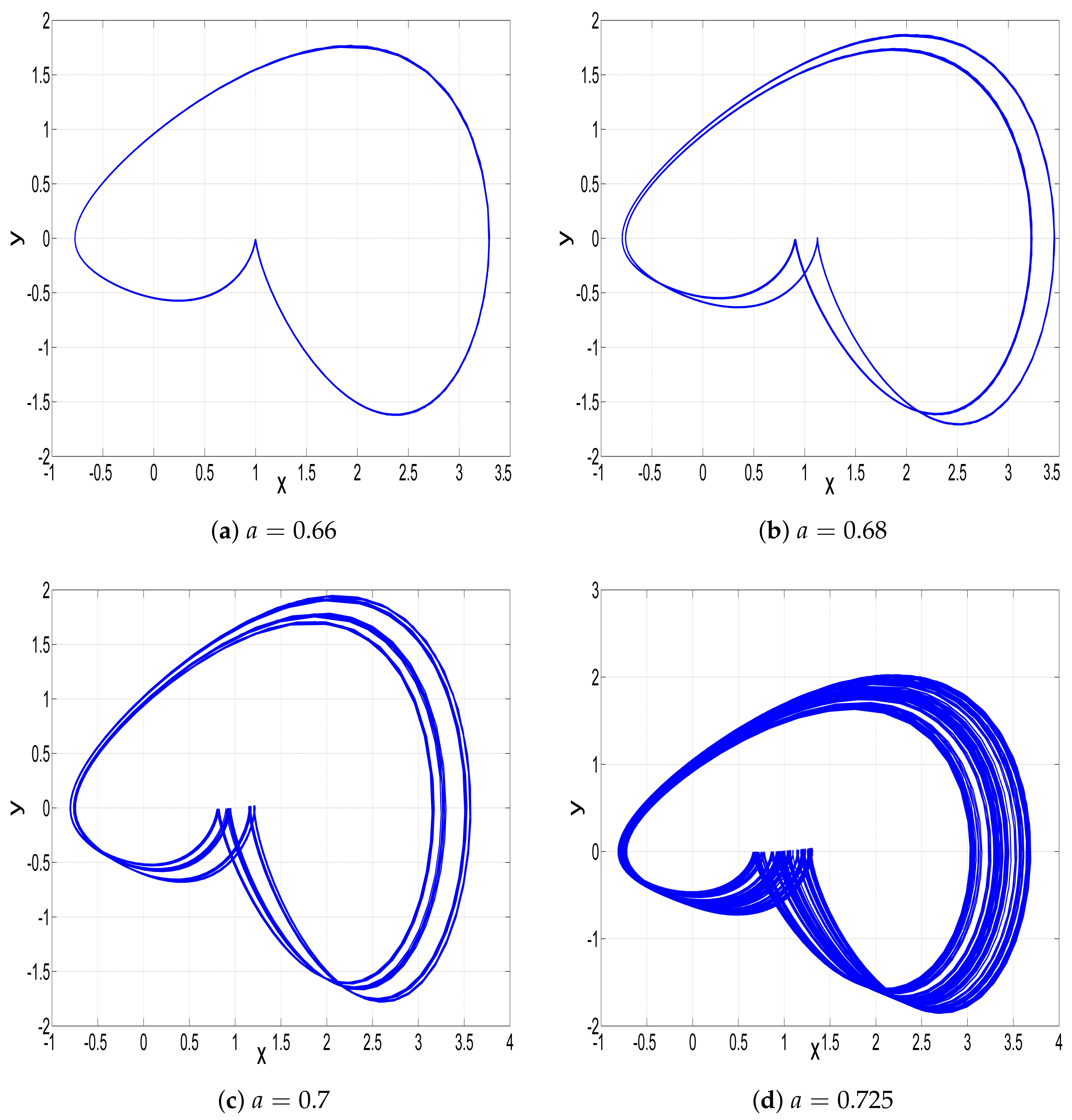
When a [ 0.65 , 0.67 ] , the jerk system (4) has one zero LE value and two negative LE values, as seen in Figure 2b, indicating that the jerk system (4) produces a periodic attractor. It is clearly seen from Figure 2c that the jerk system generates a periodic attractor in the interval [ 0.65 , 0.67 ] . The corresponding plot in ( x , y ) -plane is shown in Figure 3a.
When a [ 0.67 , 0.699 ] , the phase plot of the jerk system (4) shows a Period-2 attractor, as depicted in Figure 3b, which is very consistent with the bifurcation diagram shown in Figure 2c. The Period-4 attractor is clearly shown in Figure 3c when a [ 0.699 , 0.71 ] . It is also depicted in Figure 2c.
When a [ 0.71 , 1 ] , generally, the jerk system (4) has one positive LE value, as shown in Figure 2b, indicating that it exhibits chaotic behavior, as depicted in Figure 2a.
When a = 0.725 , the positive LE is very close to zero, providing weak chaoticity, as illustrated by Figure 3d. When a = 1 , the positive LE is large, providing stronger chaoticity, as illustrated by the ( x , y ) -plot of the chaotic attractor shown in Figure 1a. We also note that a small window of periodic behavior appears when a [ 0.892 , 0.905 ] , as depicted in Figure 2c.

3.2. When the Parameter b Varies

In this subsection, we fix the values of the parameters a and c as a = 1 and c = 0.1 , and allow the parameter b to vary in the interval [ 0.8 , 2.1 ] . It can be observed that the jerk system exhibits both periodic and chaotic behavior. Also, the jerk system experiences the dynamic property of reversal period-doubling exciting from chaos.
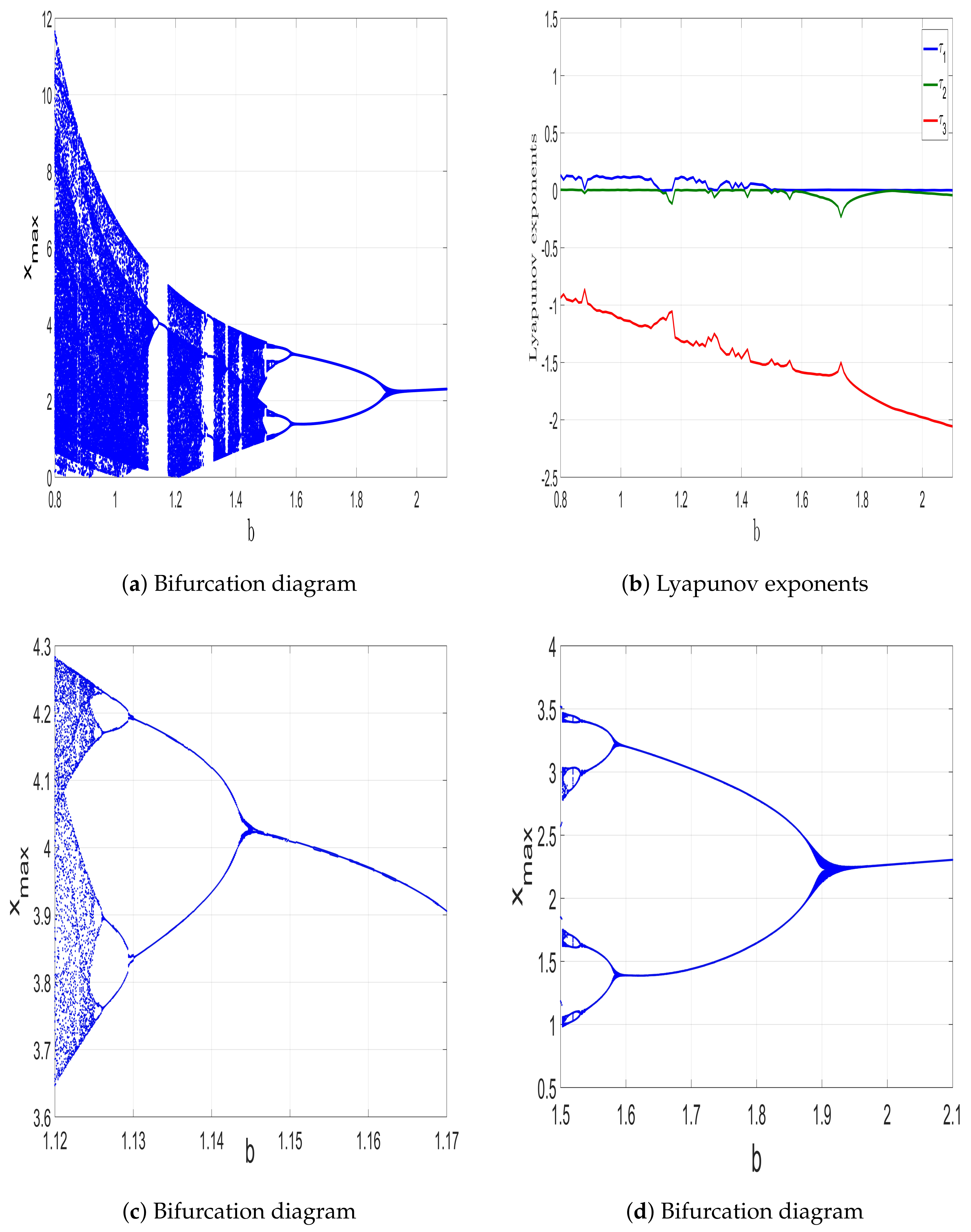
We analyze the corresponding dynamical behavior of the system (4) using Lyapunov exponents (LEs), as shown in Figure 4b and the bifurcation diagram depicted in Figure 4a. Additionally, Figure 4c provides a zoomed-in view of the bifurcation diagram, specifically focusing on the region where the first reverse period-doubling occurs. Furthermore, Figure 4d offers a zoomed-in view of the bifurcation diagram, specifically focusing on the region where the second reverse period-doubling occurs. From the above-mentioned figures, it can be observed that the jerk system (4) can exhibit both periodic and chaotic behavior. Additionally, the system demonstrates the dynamical property of reverse period-doubling, wherein it transitions from a chaotic state to periodic behavior.
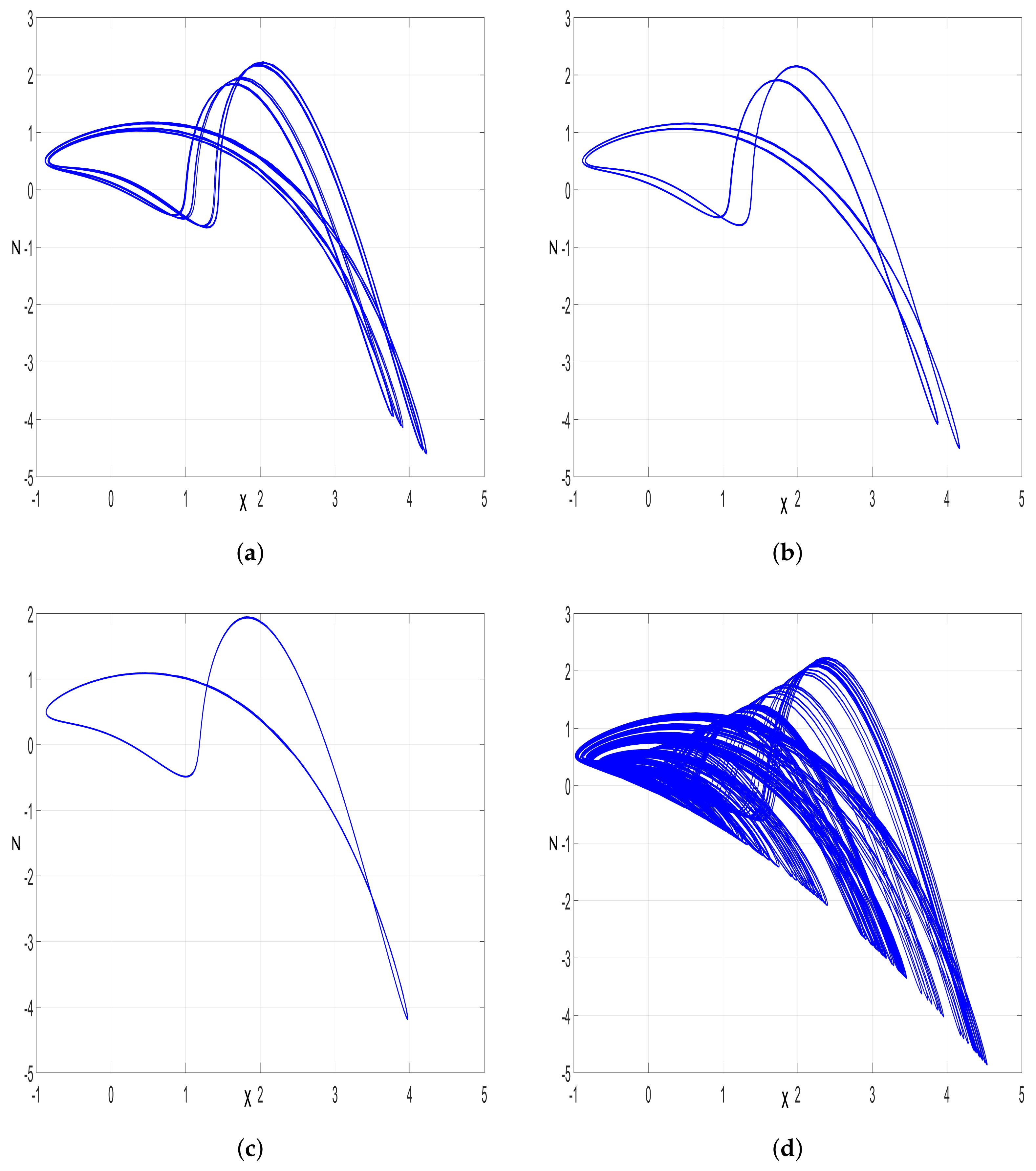
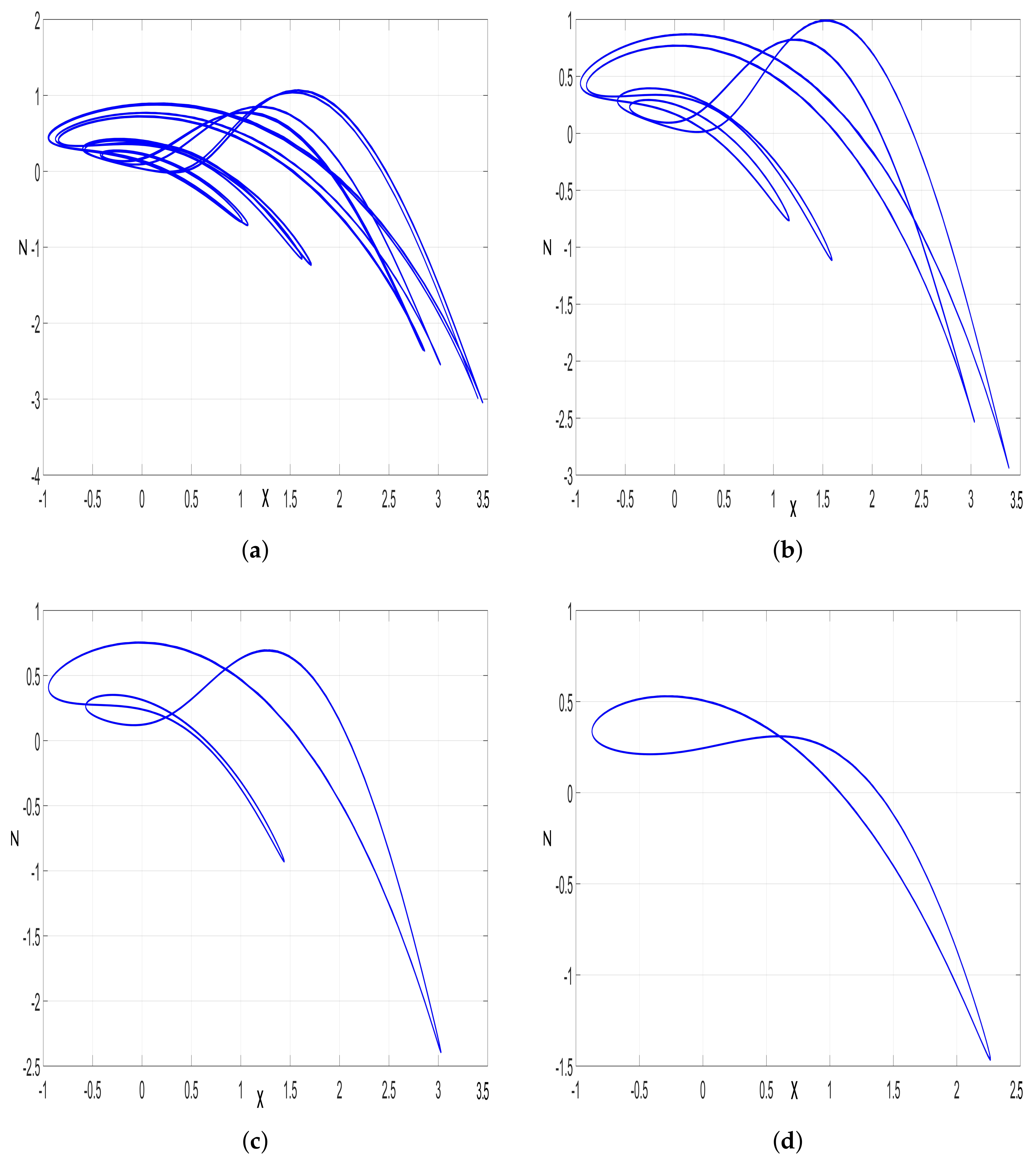
When b [ 0.8 , 1.124 ] , the jerk system has one positive LE value, as seen in Figure 4b, indicating that it produces a chaotic attractor. When b = 1 , the corresponding plot of a chaotic attractor in ( x , z ) -plane is shown in Figure 1c. Also, it is noted that there are two windows of periodic behavior when b = 0.88 and b = 0.885 . The jerk system leaves the first region of chaos via a reversal period-doubling route as follows: When b [ 1.124 , 1.130 ] , it can be seen from Figure 4c that the jerk system generates a Period-4 attractor in this region of b. The corresponding phase plot of the jerk system in ( x , z ) -plane is shown in Figure 5a.
When b [ 1.130 , 1.145 ] , the phase plot of the jerk system shows a Period-2 attractor, as depicted in Figure 5b, which is very consistent with the bifurcation diagram given in Figure 4c.
The period-1 attractor is shown in Figure 5c, when b [ 1.145 , 1.175 ] . It is also illustrated in the bifurcation diagram depicted in Figure 4c. After that, the jerk system reaches the second region of chaos when b [ 1.175 , 1.5 ] . In this interval, (4) has one positive LE, as shown in Figure 4b, indicating that it exhibits chaotic behavior, as illustrated in Figure 5d. Moreover, three windows of periodic behavior appear inside this region of chaos when b S , where S = [ 1.285 , 1.326 ] [ 1.365 , 1.374 ] [ 1.41 , 1.42 ] .
The jerk system (4) leaves the second region of chaos via a second cascade of reversal period-doubling route as follows: when b [ 1.5 , 1.53 ] , it can be seen from the bifurcation diagram shown in Figure 4d that the jerk system generates a Period-8 attractor. The corresponding phase plot in the ( x , z ) -plane is shown in Figure 6a. When b [ 1.53 , 1.59 ] , the phase plot of the jerk system (4) shows a Period-4 attractor, as depicted in Figure 6b, which is very consistent with the bifurcation diagram shown in Figure 4d.
The Period-2 attractor is shown in Figure 6c when b [ 1.59 , 1.95 ] . Finally, the reversal period-doubling cascade ends with the appearance of the Period-1 attractor when b [ 1.95 , 2.1 ] , as shown in Figure 6d.

3.3. When the Parameter c Varies

In this subsection, we fix the parameters as a = 1 and b = 1 , and allow c to vary in the interval [ 0 , 0.5 ] . It can be observed that (4) exhibits both periodic and chaotic behavior. Also, the jerk system experiences two dynamical properties of anti-monotonicity and reversal period-doubling from chaos. Then, we analyze the corresponding dynamical behavior of the jerk system (4) using Lyapunov exponents (LEs), as shown in Figure 7b and the bifurcation diagram depicted in Figure 7a. Additionally, Figure 7c provides a zoomed-in view of the bifurcation diagram, specifically focusing on the region where the phenomenon of antimonotonicity occurs. Furthermore, Figure 7d offers a zoomed-in view of the bifurcation diagram, specifically focusing on the region where the reverse period-doubling occurs. From the above-mentioned figures, it can be observed that the jerk system (4) exhibits both periodic and chaotic behavior. Moreover, the system demonstrates two dynamic properties: antimonotonicity and reverse period-doubling, the latter leading to the emergence of periodic behavior from chaos.
When c [ 0 , 0.23 ] , the jerk system has one positive LE value, as seen in Figure 7b, indicating that the jerk system (4) produces a chaotic attractor. When c = 0.1 , the corresponding plot of a chaotic attractor in the ( y , z ) -plane is shown in Figure 1b. Also, it is noted that there is a tiny window of periodic behavior sandwiched in the interval [ 0.173 , 0.179 ] .
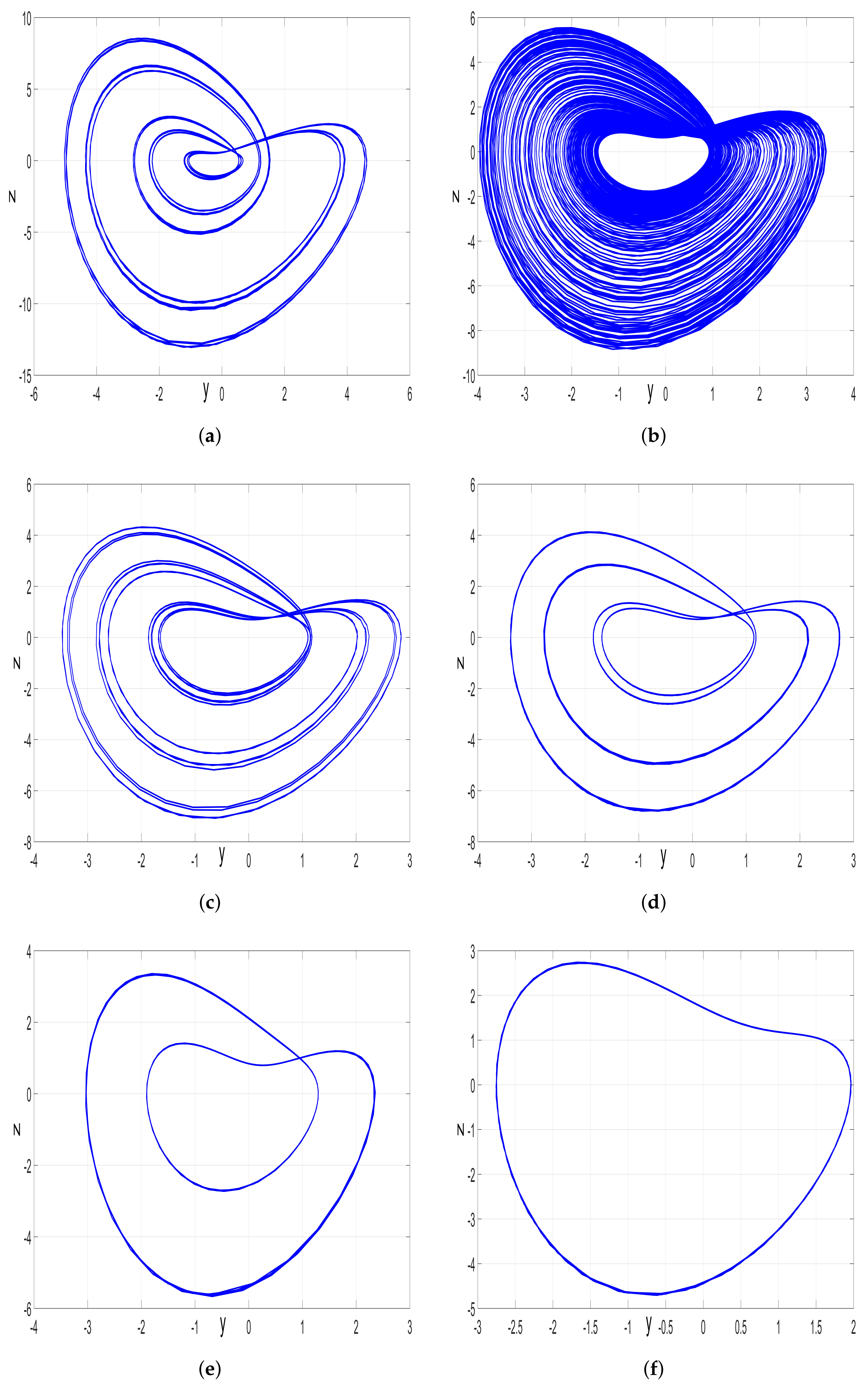
When c [ 0.23 , 0.31 ] , the jerk system enters into a periodic region wherein it experiences the phenomenon of antimonotonicity, as illustrated in Figure 7c. An example of the attractor’s shapes produced by the jerk system in this region is plotted in Figure 8a. When c [ 0.31 , 0.35 ] , a second region of chaos appears, as clearly shown in Figure 7a, wherein the jerk system exhibits chaotic behavior, as illustrated in Figure 8b.
The jerk system (4) leaves the second region of chaos via a reversal period-doubling route as follows: When c [ 0.35 , 0.356 ] , it can be seen from Figure 7a that the jerk system (4) generates a Period-8 attractor in this region of c as shown in Figure 8d. When c [ 0.356 , 0.373 ] , the phase plot shows a Period-4 attractor, as depicted in Figure 8d, which is very consistent with the bifurcation diagram given in Figure 7d. The Period-2 attractor is shown in Figure 8e, when c [ 0.373 , 0.433 ] . Finally, the reversal period-doubling cascade ends with the appearance of a Period-1 attractor when c [ 0.433 , 0.5 ] , as shown in Figure 8f.

4. Multistability of the Jerk System

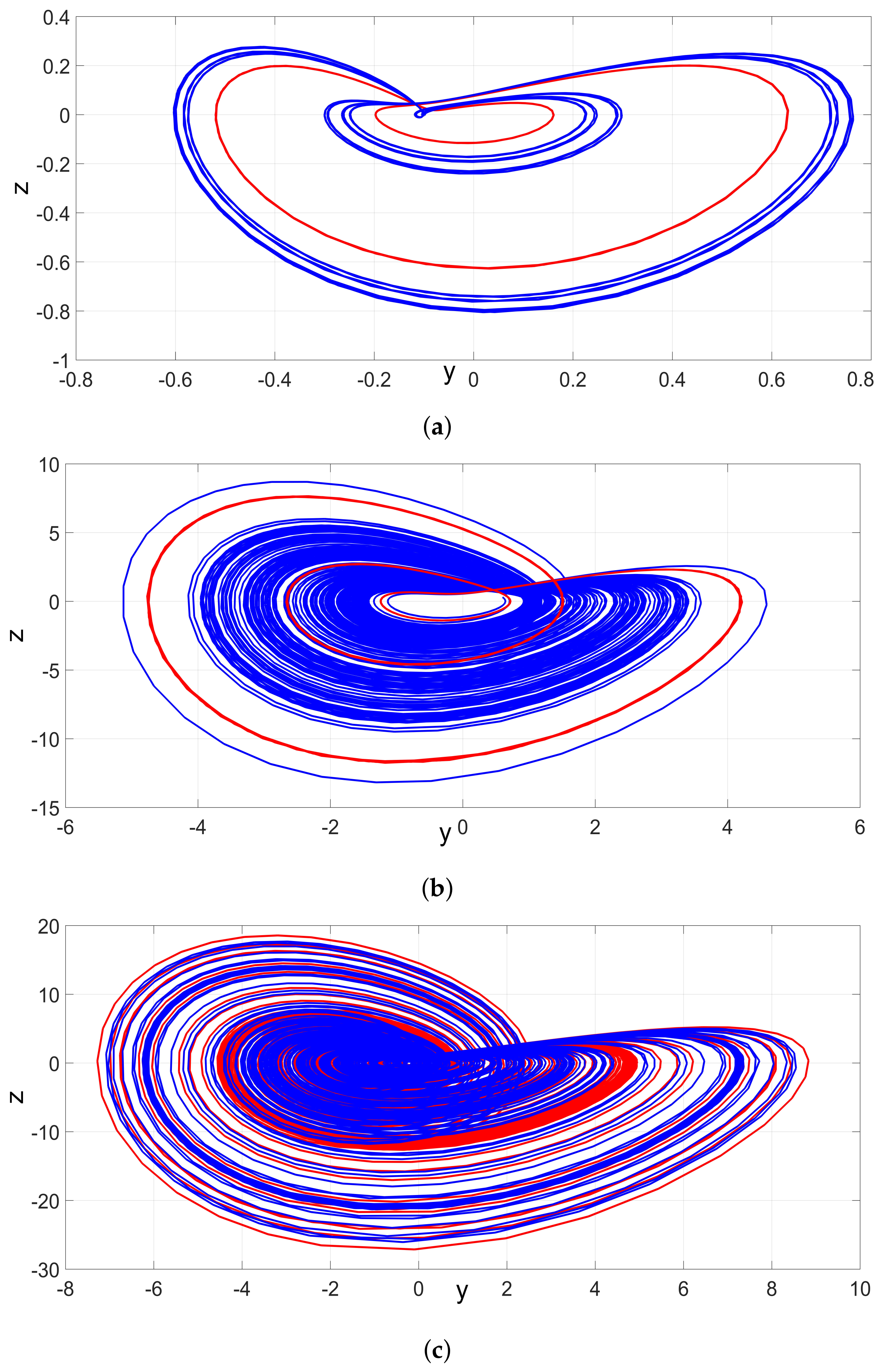
Here, we concentrate on how different initial values affect the new 3-D jerk system’s dynamics. We show that (4) can generate different attractors for the same values of parameters but for different initial states. In Figure 9a–c, the phase plot of the jerk system (4) starting from Z 0 = ( 0.6 , 0.6 , 0.3 ) appears in blue color, while the phase plot of the jerk system starting from Z 1 = ( 0.1 , 0.1 , 0.1 ) appears in red color.
When the coefficient parameters of the new 3-D jerk system are chosen as a = 0.24 , b = 1 and c = 0.1 , the system generates two different coexisting periodic attractors, as shown in Figure 9a. When a = 1 , b = 1 , and c = 0.32 , the jerk system (4) entails coexistence of one periodic attractor and one chaotic attractor, as displayed in Figure 9b. When a = 1.45 , b = 1 , and c = 0.1 , the jerk system (4) generates two different coexisting chaotic attractors, as seen in Figure 9c.

5. Complete Synchronization of the New Jerk Systems Using Backstepping Control

Making use of the special structure of the proposed jerk system, we use the backstepping control method to achieve complete synchronization between the master and slave chaotic jerk systems. The backstepping control method is a recursive design process which is useful for the asymptotic stabilization of nonlinear control systems [30]. The backstepping control technique provides a systematic framework for designing nonlinear controllers by using Lyapunov stability theory. The backstepping control method has also been applied for the synchronization of other types of chaotic systems [31,32]. The synchronization of chaotic systems has many applications in secure communication systems [33,34].
For the synchronization design, we consider the master and slave jerk systems as follows:
x ˙ m = y m y ˙ m = z m z ˙ m = a x m b z m x m y m c x m 2 + y m 2
x ˙ s = y s y ˙ s = z s z ˙ s = a x s b z s x s y s c x s 2 + y s 2 + w
In Equation (19), w is an active control, which is designed using the backstepping control method in this section.
We define the complete synchonization error by the following equations:
E x = x s x m E y = y s y m E z = z s z m
The error dynamics are derived by the following equations:
E ˙ x = E y E ˙ y = E z E ˙ z = a E x b E z x s y s + x m y m c ( x s 2 x m 2 ) + y s 2 y m 2 + w
In this section, we shall establish the following main result.
Theorem 1.
The backstepping control law defined by the equation
w = ( 2 a ) E x 5 E y ( 3 b ) E z + x s y s x m y m + c ( x s 2 x m 2 ) y s 2 + y m 2 K α z
with  K > 0  and  α z = 2 E x + 2 E y + E z  exponentially stabilizes the new chaotic jerk systems (18) and (19) for all initial states in  R 3 .
Proof. 
To start the backstepping control method, we use the Lyapunov function
Q 1 ( α x ) = 1 2 α x 2 ,
where
α x = E x
A simple calculation shows that
Q 1 ˙ = α x α ˙ x = α x 2 + α x ( E x + E y )
Next, we define
α y = E x + E y
Then, we can simplify Equation (25) as follows:
Q 1 ˙ = α x 2 + α x α y
In the second step of the backstepping control method, we take the Lyapunov function
Q 2 ( α x , α y ) = Q 1 ( α x ) + 1 2 α y 2 = 1 2 α x 2 + 1 2 α y 2
It is easy to verify that
Q ˙ 2 = α x 2 α y 2 + α y ( 2 E x + 2 E y + E z )
Next, we define
α z = 2 E x + 2 E y + E z
Then, we can simplify Equation (29) as follows:
Q ˙ 2 = α x 2 α y 2 + α y α z
As the final step of the backstepping control design, we take the quadratic Lyapunov function defined as follows:
Q ( α x , α y , α z ) = Q 2 ( α x , α y ) + 1 2 α z 2 = 1 2 α x 2 + 1 2 α y 2 + 1 2 α z 2
Thus, we find the following:
Q ˙ = α x 2 α y 2 α z 2 + α z T
where
T = α y + α z + α ˙ z
A simple calculation gives
T = ( 2 a ) E x + 5 E y + ( 3 b ) E z x s y s + x m y m c ( x s 2 x m 2 ) + y s 2 y m 2 + w
Substituting the formula given in Equation (22) for w into Equation (35), we obtain
T = K α z
Combining (33) and (36), we obtain
Q ˙ = α x 2 α y 2 α z 2 ( 1 + K )
Since the gain K is positive, we see that Q ˙ is a quadratic and negative definite function defined on R 3 .
By application of Lyapunov stability theory [30], we deduce that the error dynamics (21) are globally exponentially stable.
This completes the proof. □
For MATLAB simulations, we take the parameter values as in the chaotic case:
a = 1 , b = 1 , c = 0.1
Also, we set K = 25 .
The initial states of the master and slave jerk systems represented by (18) and (19) are taken as follows:
x m ( 0 ) = 1.2 , y m ( 0 ) = 0.6 , z m ( 0 ) = 5.9 , x s ( 0 ) = 0.4 , y s ( 0 ) = 4.7 , z s ( 0 ) = 1.9
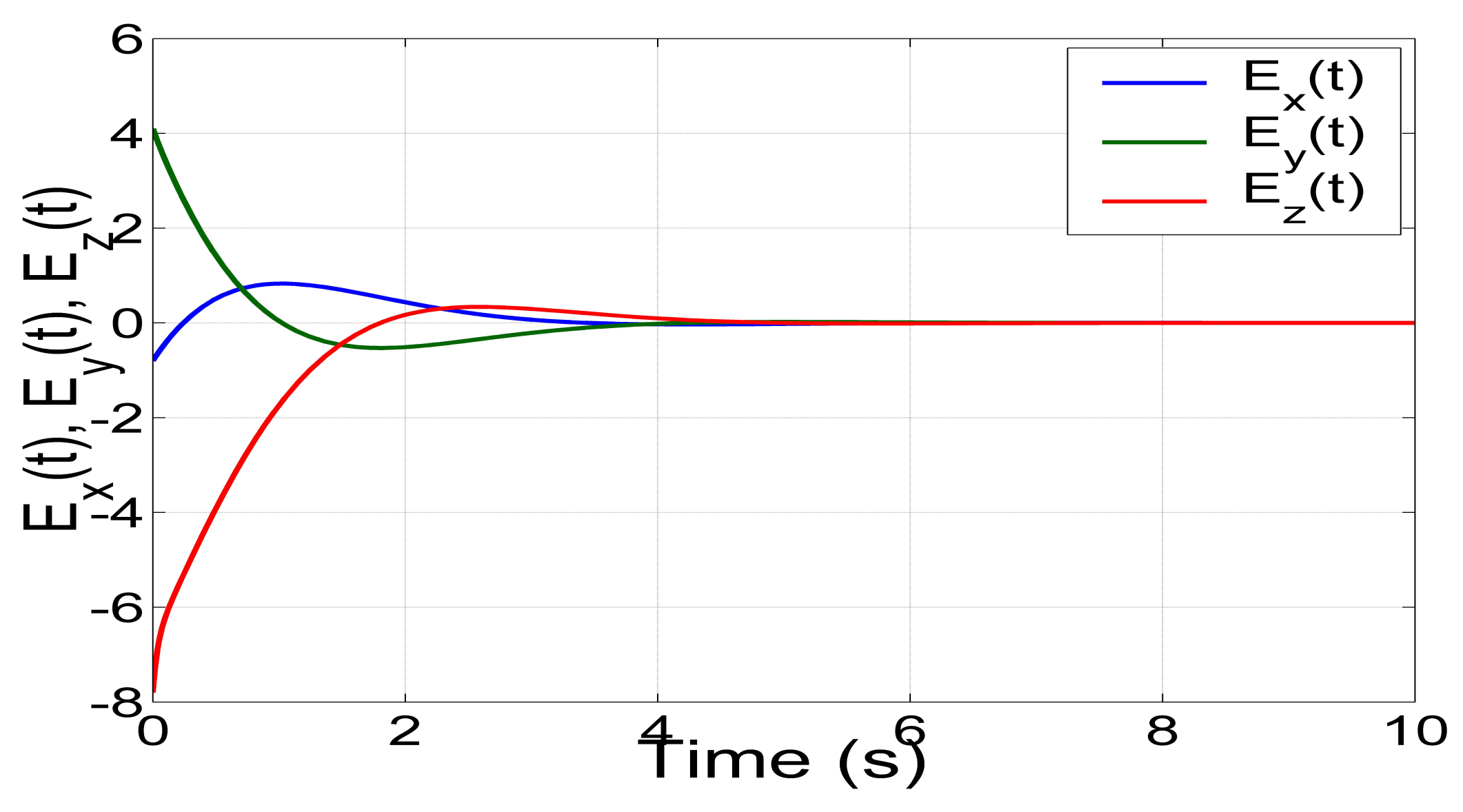
Figure 10 shows the convergence of the synchronization error ( E x ( t ) , E y ( t ) , E z ( t ) ) between the jerk systems (18) and (19).

6. FPGA Implementation of the New Jerk System

As already shown in several recent works, the FPGA implementation of a chaotic system, like the new 3-D Jerk one, requires the application of numerical methods, and the most simple and commonly used is the well-known forward Euler (FE) method.
On the one hand, the discretized equations of the new 3-D chaotic jerk system with two unstable balance points by applying FE method are given in (40). On the other hand, and as already mentioned in [28], another way to discretize the equations of a chaotic system is by applying a more elaborated method as the trapezoidal one, for which the discretized equations are given in (41). One can identify that the iterative equations given in (40) can be solved by just providing the initial conditions, since the mathematical model of the new 3-D chaotic jerk system is an initial value problem. However, when applying an implicit method, such as the trapezoidal one, the iterative equations given in (41) require the estimation of the values of the state variables on the right-hand side, which are evaluated at index [n + 1]. In this case, the estimated value is usually evaluated by an explicit method, such as FE. In such a case, one can evaluate the equations given in (40) to estimate the iteration [n + 1], and the result can be used to evaluate the discretized equations given in (41).
x n + 1 = x n + h y n y n + 1 = y n + h z n z n + 1 = z n + h ( a x n b z n x n y n c x n 2 + y n 2 )
x n + 1 = x n + h ( y n + y n + 1 ) y n + 1 = y n + h ( z n + z n + 1 ) z n + 1 = z n + h ( a x n b z n x n y n c x n 2 + y n 2 a x n + 1 b z n + 1 x n + 1 y n + 1 c x n + 1 2 + y n + 1 2 )
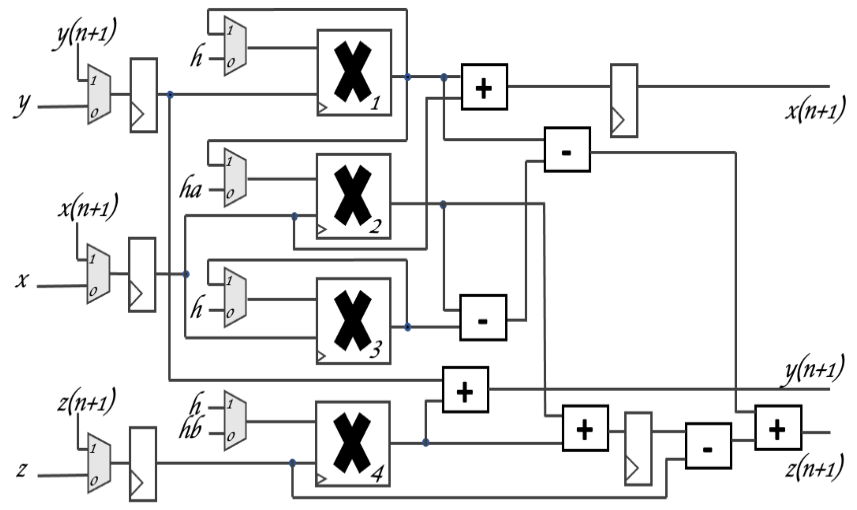
Using the coefficient values a = 1 , b = 1 , c = 0.1 , with initial conditions ( 0.3 , 0.2 , 0.3 ) , and by setting the time-step to h = 0.001 , one can observe the experimental results from the FPGA implementation. The block description of the new 3-D chaotic jerk system is given in Figure 11. One can see that it is not a direct description from (40). It was manipulated to perform pipeline operations, thus resulting in a connection of blocks that are associated with the multiplexers, registers, multipliers, adders, and subtractors. Each block can perform fixed-point arithmetic and uses 24-bit words, assuming 1 bit for the sign, 5 bits for the integer part and 19 bits for the fractional representation. Table 1 shows the hardware resources of the implementation by using the FPGA Zybo Z7-20 board (XC7Z020CLG400-1). The design was developed in the Xilinx Vivado tool, and the hardware description was carried out in the VHDL language.
In Figure 11, the use of just four multipliers, four adders, three subtractors and nine registers is shown. This is a very nice hardware design since the direct implementation of (40) requires nine multipliers: three that multiply h, two to evaluate x n 2 and y n 2 , one to multiply x n y n , and three to multiply the coefficients a , b , c . This compact design using only four multipliers, as shown in Figure 11, performs pipeline operations. A finite state machine (FSM) is implemented to generate the control signals of the seven multiplexers that controls the reuse of some multipliers to enable an efficient hardware design. The pre-computation of new constants ( h a = h a , h b = h b ), as well as the re-ordering of the executions of the operations, are performed to consume only two clock cycles when evaluating an iteration.
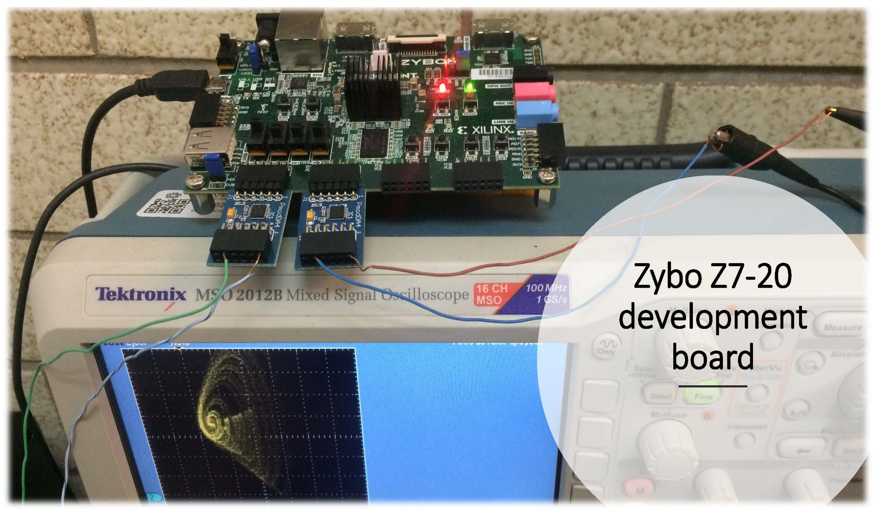
Figure 12 shows the experimental setup featuring the oscilloscope, the FPGA Zybo Z7-20 (XC7Z020CLG400-1), and two digital-to-analog converters (DACs). Figure 13 presents the experimental phase portraits of some combinations of the state variables of the proposed system observed in an oscilloscope.

7. Conclusions

In this research manuscript, we reported a new 3-D chaotic jerk system with two unstable balance points. We illustrated that the proposed jerk system exhibits multistability with coexisting periodic and chaotic attractors for different initial states. A bifurcation analysis of the proposed mechanical jerk system was described elaborating the special dynamical properties of the new jerk system.
The FPGA implementation of the proposed mechanical jerk system was successfully accomplished using the FPGA Zybo Z7-20 (XC7Z020CLG400-1) to synthesize the discrete dynamical equations obtained by applying numerical methods. It was shown that the direct implementation of the mathematical model requires nine multipliers; however, an appropriate factorization led us to use only four connected multipliers to perform pipeline operations. Finally, the experimental results of the proposed mechanical jerk system using FPGA-based design showed good agreement with the MATLAB simulations of the same system. As future research work, applications of the proposed mechanical jerk system in areas such as secure communications, steganography and cryptosystems can be studied.

Author Contributions

Conceptualization, S.V. and E.T.-C.; methodology, K.B., A.S. and B.O.-M.; software, B.O.-M.; formal analysis, S.V., E.T.-C., K.B. and A.S.; investigation, S.V.; writing—original draft preparation, S.V., E.T.-C. and B.O.-M.; writing—review and editing, S.V., E.T.-C., K.B., A.S. and B.O.-M.; supervision, S.V. All authors have read and agreed to the published version of the manuscript.

Funding

This research received no external funding.

Data Availability Statement

Not applicable.

Conflicts of Interest

The authors declare no conflict of interest.

References

  1. Reis, E.V.; Savi, M.A. Spatiotemporal chaos in a conservative Duffing-type system. Chaos Solitons Fractals 2022, 165, 112776. [Google Scholar] [CrossRef]
  2. Cai, C.; Shen, Y.; Wen, S. Primary and super-harmonic simultaneous resonance of van der Pol oscillator. Int. J. Non-Linear Mech. 2022, 147, 104237. [Google Scholar] [CrossRef]
  3. Madiot, G.; Correia, F.; Barbay, S.; Braive, R. Random number generation with a chaotic electromechanical resonator. Nanotechnology 2022, 33, 475204. [Google Scholar] [CrossRef]
  4. Balamurali, R.; Telem, A.N.K.; Kengne, J.; Rajagopal, K.; Hermann-Dior, M.E. On the mechanism of multiscroll chaos generation in coupled non-oscillatory Rayleigh-Duffing oscillators. Phys. Scr. 2022, 97, 105207. [Google Scholar] [CrossRef]
  5. Liu, H. Audio block encryption using 3D chaotic system with adaptive parameter perturbation. Multimed. Tools Appl. 2023, 82, 27973–27987. [Google Scholar] [CrossRef]
  6. Dongmo, E.D.; Ramadoss, J.; Tchamda, A.R.; Sone, M.E.; Rajagopal, K. FPGA implementation, controls and synchronization of autonomous Josephson junction jerk oscillator. Phys. Scr. 2023, 98, 035224. [Google Scholar] [CrossRef]
  7. Mohamed, S.M.; Sayed, W.S.; Madian, A.H.; Radwan, A.G.; Said, L.A. An Encryption Application and FPGA Realization of a Fractional Memristive Chaotic System. Electronics 2023, 12, 1219. [Google Scholar] [CrossRef]
  8. Dridi, F.; El Assad, S.; Youssef, W.E.H.; Machhout, M. Design, Hardware Implementation on FPGA and Performance Analysis of Three Chaos-Based Stream Ciphers. Fractal Fract. 2023, 7, 197. [Google Scholar] [CrossRef]
  9. Sun, J.Y.; Cai, H.; Wang, G.; Gao, Z.B.; Zhang, H. FPGA image encryption-steganography using a novel chaotic system with line equilibria. Digit. Signal Process. 2023, 134, 103889. [Google Scholar]
  10. Sprott, J.C. Some simple chaotic jerk functions. Am. J. Phys. 1997, 65, 537–543. [Google Scholar] [CrossRef]
  11. Sun, K.H.; Sprott, J.C. A simple jerk system with piecewise exponential nonlinearity. Int. J. Nonlinear Sci. Numer. Simul. 2000, 10, 1443–1450. [Google Scholar] [CrossRef]
  12. Liu, M.; Sang, B.; Wang, N.; Ahmad, I. Chaotic dynamics by some quadratic jerk systems. Axioms 2021, 10, 227. [Google Scholar] [CrossRef]
  13. Vaidyanathan, S.; Volos, C.K.; Kyprianidis, I.M.; Stouboulos, I.N.; Pham, V.T. Analysis, adaptive control and anti-synchronization of a six-term novel jerk chaotic system with two exponential nonlinearities and its circuit simulation. J. Eng. Sci. Technol. Rev. 2021, 8, 24–36. [Google Scholar] [CrossRef]
  14. Rajagopal, K.; Pham, V.T.; Tahir, F.R.; Akgul, A.; Abdolmohammadi, H.R.; Jafari, S. A chaotic jerk system with non-hyperbolic equilibrium: Dynamics, effect of time delay and circuit realisation. Pramana J. Phys. 2018, 90, 52. [Google Scholar] [CrossRef]
  15. Ramakrishnan, B.; Tamba, V.K.; Natiq, H.; Tsafack, A.S.K.; Karthikeyan, A. Dynamical analysis of autonomous Josephson junction jerk oscillator with cosine interference term embedded in FPGA and investigation of its collective behavior in a network. Eur. Phys. J. B 2022, 95, 145. [Google Scholar] [CrossRef]
  16. Tagne, S.; Bodo, B.; Eyebe, G.F.V.A.; Fouda, J.S.A.E. PIC micro-controller based synchronization of two fractional order jerk systems. Sci. Rep. 2022, 12, 14281. [Google Scholar] [CrossRef]
  17. Wang, Q.; Tian, Z.; Wu, X.; Tan, W. Coexistence of multiple attractors in a novel simple jerk chaotic circuit with CFOAs implementation. Front. Phys. 2022, 10, 835188. [Google Scholar] [CrossRef]
  18. Wei, M.; Han, X.; Ma, X.; Zou, Y.; Bi, Q. Bursting patterns with complex structures in a parametrically and externally excited Jerk circuit system. Eur. Phys. J. Spec. Top. 2022, 231, 2265–2275. [Google Scholar] [CrossRef]
  19. Kamdem Tchiedjo, S.; Kamdjeu Kengne, L.; Kengne, J.; Djuidje Kenmoe, G. Dynamical behaviors of a chaotic jerk circuit based on a novel memristive diode emulator with a smooth symmetry control. Eur. Phys. J. Plus 2022, 137, 940. [Google Scholar] [CrossRef]
  20. Kengne, L.K.; Muni, S.S.; Chedjou, J.C.; Kyandoghere, K. Various coexisting attractors, asymmetry analysis and multistability control in a 3D memristive jerk system. Eur. Phys. J. Plus 2022, 137, 848. [Google Scholar] [CrossRef]
  21. Njitacke, Z.T.; Feudjio, C.; Signing, V.F.; Koumetio, B.N.; Tsafack, N.; Awrejcewicz, J. Circuit and microcontroller validation of the extreme multistable dynamics of a memristive Jerk system: Application to image encryption. Eur. Phys. J. Plus 2022, 137, 619. [Google Scholar] [CrossRef]
  22. Méndez-Ramírez, R.; Arellano-Delgado, A.; Cruz-Hernández, C.; Martínez-Clark, R. A new simple chaotic LLorenz-type system and its digital realization using a TFT touch-screen display embedded system. Complexity 2017, 2017, 6820492. [Google Scholar] [CrossRef] [Green Version]
  23. Gupta, A.; Dubey, B. Bifurcation and chaos in a delayed eco-epidemic model induced by prey configuration. Chaos Solitons Fractals 2022, 165, 112785. [Google Scholar] [CrossRef]
  24. Xing, J.; Yang, Z.; Ren, Y. Analysis of bifurcation and chaotic behavior for the flexspline of an electromagnetic harmonic drive system with movable teeth transmission. Appl. Math. Model. 2022, 112, 467–485. [Google Scholar] [CrossRef]
  25. Yan, H.; Qiao, Y.; Ren, Z.; Duan, L.; Miao, J. Master–slave synchronization of fractional-order memristive MAM neural networks with parameter disturbances and mixed delays. Commun. Nonlinear Sci. Numer. Simul. 2023, 120, 107152. [Google Scholar] [CrossRef]
  26. Kumar, S.; Prasad, R.P.; Nishad, C.; Tiwary, A.K.; Khan, F. Analysis and chaos synchronization of Genesio–Tesi system applying sliding mode control techniques. Int. J. Dyn. Control 2023, 11, 656–665. [Google Scholar] [CrossRef]
  27. Dousseh, Y.P.; Monwanou, A.V.; Koukpémèdji, A.A.; Miwadinou, C.H.; Chabi Orou, J.B. Dynamics analysis, adaptive control, synchronization and anti-synchronization of a novel modified chaotic financial system. Int. J. Dyn. Control 2023, 11, 862–876. [Google Scholar] [CrossRef]
  28. Benkouider, K.; Vaidyanathan, S.; Sambas, A.; Tlelo-Cuautle, E.; Abd El-Latif, A.A.; Abd-El-Atty, B.; Bermudez-Marquez, C.F.; Sulaiman, I.M.; Awwal, A.M.; Kumam, P. A New 5-D Multistable Hyperchaotic System With Three Positive Lyapunov Exponents: Bifurcation Analysis, Circuit Design, FPGA Realization and Image Encryption. IEEE Access 2022, 10, 90111–90132. [Google Scholar] [CrossRef]
  29. Valencia-Ponce, M.A.; Castañeda-Aviña, P.R.; Tlelo-Cuautle, E.; Carbajal-Gómez, V.H.; González-Díaz, V.R.; Sandoval-Ibarra, Y.; Nuñez-Perez, J.C. CMOS OTA-based filters for designing fractional-order chaotic oscillators. Fractal Fract. 2021, 5, 122. [Google Scholar] [CrossRef]
  30. Vaidyanathan, S.; Azar, A.T. Backstepping Control of Nonlinear Dynamical Systems; Academic Press: New York, NY, USA, 2021. [Google Scholar]
  31. Dong, H.; Cao, J.; Liu, H. Observers-based event-triggered adaptive fuzzy backstepping synchronization of uncertain fractional order chaotic systems. Chaos 2023, 33, A366. [Google Scholar] [CrossRef]
  32. Yan, S.; Wang, J.; Wang, E.; Wang, Q.; Sun, X.; Li, L. A four-dimensional chaotic system with coexisting attractors and its backstepping control and synchronization. Integration 2023, 91, 67–78. [Google Scholar] [CrossRef]
  33. He, J.; Qiu, W.; Cai, J. Synchronization of hyperchaotic systems based on intermittent control and its application in secure communication. J. Adv. Comput. Intell. Intell. Inform. 2023, 27, 292–303. [Google Scholar] [CrossRef]
  34. Gong, X.; Wang, H.; Ji, Y.; Zhang, Y. Optical chaos generation and synchronization in secure communication with electro-optic coupling mutual injection. Opt. Commun. 2022, 521, 128565. [Google Scholar] [CrossRef]
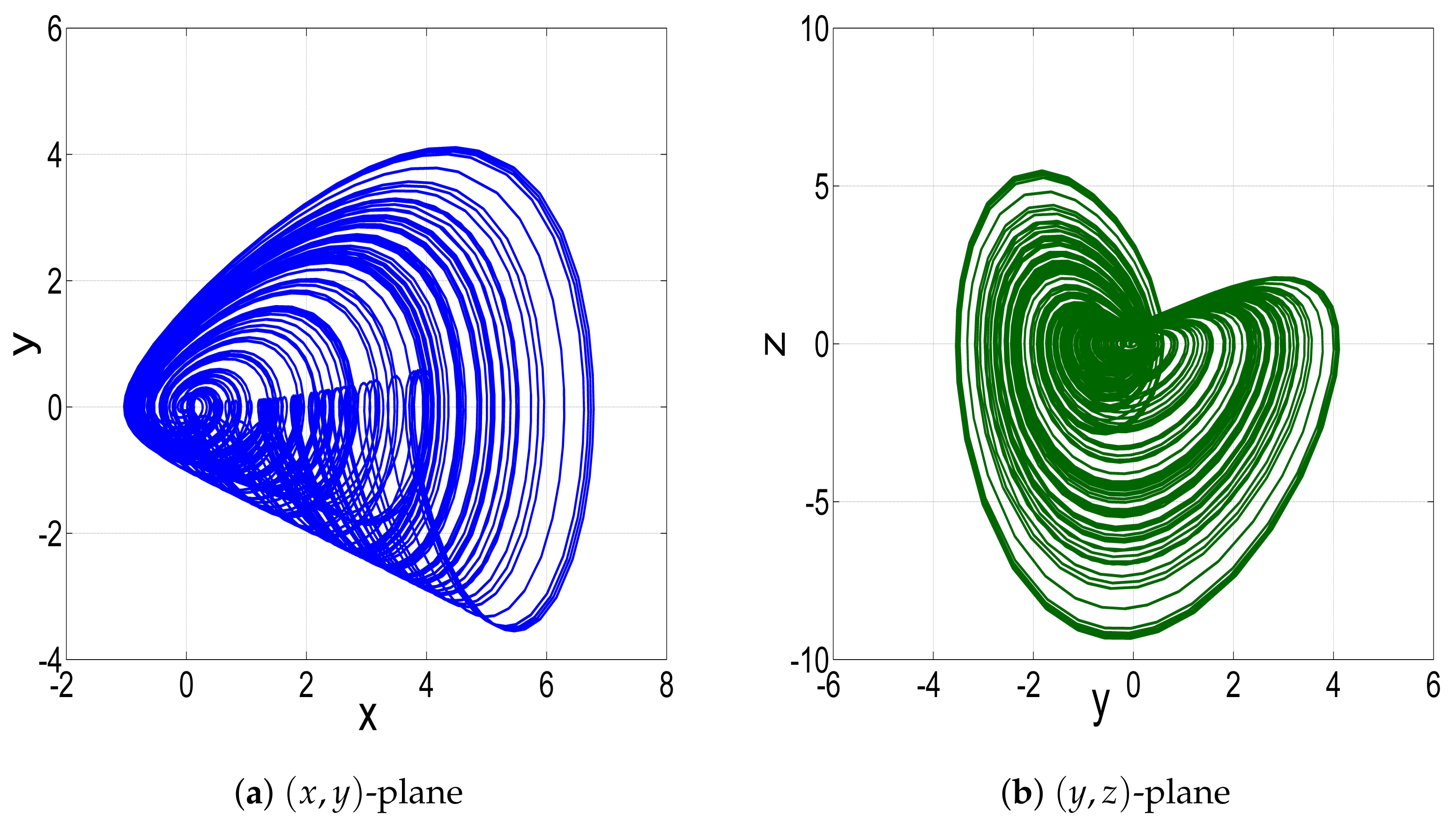
Figure 1. MATLAB simulation plots in 2-D planes and 3-D space for the new 3-D jerk system (4) corresponding to the parameter data ( a , b , c ) = ( 1 , 1 , 0.1 ) and initial data Z ( 0 ) = ( 0.3 , 0.1 , 0.3 ) .
Technologies 11 00092 g001aTechnologies 11 00092 g001b
Figure 2. (a) Bifurcation diagram, (b) LE spectrum and (c) period-doubling route for the jerk system (4) when a [ 0.65 , 1 ] , b = 1 and c = 0.1 .
Technologies 11 00092 g002
Figure 3. Phase plots of the new jerk system (4) for b = 1 , c = 0.1 and different values of a.
Technologies 11 00092 g003
Figure 4. (a) Bifurcation diagram, (b) LE spectrum, (c) the first cascade of reverse-period doubling, (d) the second cascade of reverse-period doubling for the jerk system (4) when a = 1 , b [ 0.8 , 2.1 ] and c = 0.1 .
Technologies 11 00092 g004
Figure 5. Phase plots of the new jerk system (4) for a = 1 , c = 0.1 and different values of b.
Technologies 11 00092 g005
Figure 6. Phase plots of the new jerk system (4) for a = 1 , c = 0.1 and different values of b.
Technologies 11 00092 g006
Figure 7. (a) Bifurcation diagram, (b) LEs, (c) antimonotonocity phenomena, and (d) reverse-period doubling route for the jerk system (4) when a = 1 , b = 1 and c [ 0 , 0.5 ] .
Technologies 11 00092 g007
Figure 8. Phase plots of the new jerk system (4) for c equal to: (a) 0.29, (b) 0.32, (c) 0.353, (d) 0.36, (e) 0.39, and (f) 0.48.
Technologies 11 00092 g008
Figure 9. Coexisting attractors of the jerk system (4): (a) Two coexisting periodic attractors, (b) coexistence of one periodic attractor and one chaotic attractor, and (c) two coexisting chaotic attractors.
Technologies 11 00092 g009
Figure 10. MATLAB plot showing the synchronization error ( E x , E y , E z ) between the jerk systems (18) and (19).
Technologies 11 00092 g010
Figure 11. Block diagram for the hardware design of the proposed new 3-D chaotic jerk system from (40).
Technologies 11 00092 g011
Figure 12. Experimental setup to observe the attractors.
Technologies 11 00092 g012
Figure 13. Experimental views for the attractors x y , x z , and y z , generated by setting a = 1 , b = 1 , and c = 0.1 , with initial conditions ( 0.3 , 0.2 , 0.3 ) , and h = 0.001 .
Technologies 11 00092 g013
Table 1. Utilization of the FPGA hardware resources using Xilinx Zybo Z7-20 (xc7z020clg400-1).
ResourcesUsedUtil
Slice1341.01%
LUTs3040.57%
FFs2920.21%
DSPs103.18%
Frequency Max111 MHz
Disclaimer/Publisher’s Note: The statements, opinions and data contained in all publications are solely those of the individual author(s) and contributor(s) and not of MDPI and/or the editor(s). MDPI and/or the editor(s) disclaim responsibility for any injury to people or property resulting from any ideas, methods, instructions or products referred to in the content.