
A Layer-Wise Coupled Thermo-Elastic Shell Model for Three-Dimensional Stress Analysis of Functionally Graded Material Structures


Abstract
1. Introduction
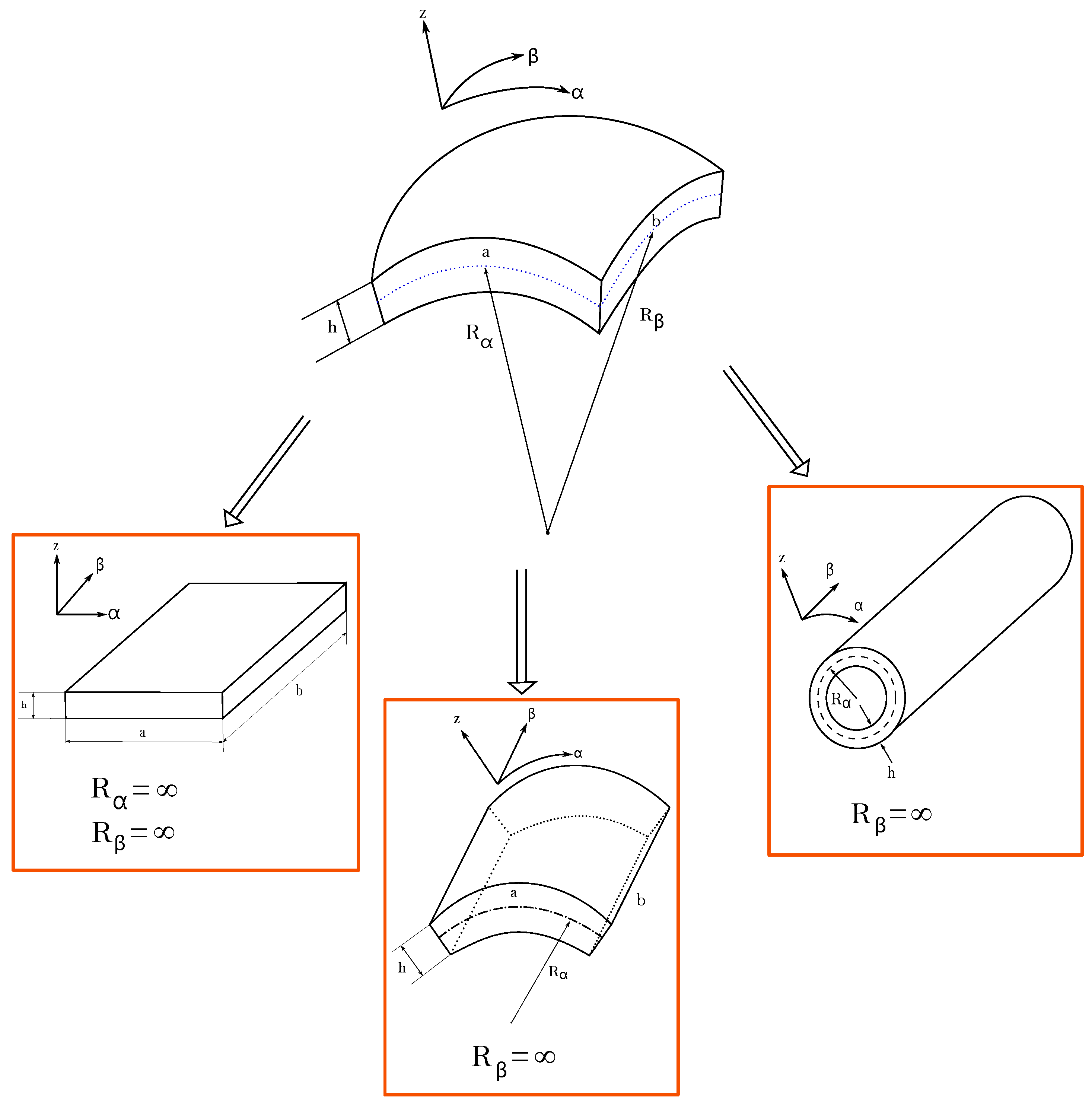
2. 3D Exact and Coupled Thermo-Elastic Governing Equations for Spherical Shells
2.1. 3D Equilibrium and Heat Conduction Equations for Spherical Shells
2.2. 3D Geometrical and Constitutive Relations
2.3. Exponential Matrix Methodology and Layer Wise Approach
3. Results
3.1. Preliminary Assessments
3.2. New Benchmarks
4. Conclusions
Author Contributions
Funding
Institutional Review Board Statement
Informed Consent Statement
Data Availability Statement
Conflicts of Interest
References
- Librescu, L.; Marzocca, P. Thermal Stresses ’03, Vol. 1; Virginia Polytechnic Institute and State University: Blacksburg, VA, USA, 2003. [Google Scholar]
- Librescu, L.; Marzocca, P. Thermal Stresses ’03, Vol. 2; Virginia Polytechnic Institute and State University: Blacksburg, VA, USA, 2003. [Google Scholar]
- Nowinski, J.L. Theory of Thermoelasticity with Applications; Sijthoff & Noordhoff: Alphen aan den Rijn, The Netherlands, 1978. [Google Scholar]
- Noor, A.K.; Burton, W.S. Computational models for high-temperature multilayered composite plates and shells. Appl. Mech. Rev. 1992, 45, 419–446. [Google Scholar] [CrossRef]
- Swaminathan, K.; Sangeetha, D.M. Thermal analysis of FGM plates—A critical review of various modeling techniques and solution methods. Compos. Struct. 2017, 160, 43–60. [Google Scholar] [CrossRef]
- Altay, G.A.; Dökmeci, M.C. Fundamental variational equations of discontinuous thermopiezoelectric fields. Int. J. Eng. Sci. 1996, 34, 769–782. [Google Scholar] [CrossRef]
- Altay, G.A.; Dökmeci, M.C. Some variational principles for linear coupled thermoelasticity. Int. J. Solids Struct. 1996, 33, 3937–3948. [Google Scholar] [CrossRef]
- Altay, G.A.; Dökmeci, M.C. Coupled thermoelastic shell equations with second sound for high-frequency vibrations of temperature-dependent materials. Int. J. Solids Struct. 2001, 38, 2737–2768. [Google Scholar] [CrossRef]
- Cannarozzi, A.A.; Ubertini, F. A mixed variational method for linear coupled thermoelastic analysis. Int. J. Solids Struct. 2001, 38, 717–739. [Google Scholar] [CrossRef]
- Das, N.C.; Das, S.N.; Das, B. Eigenvalue approach to thermoelasticity. J. Therm. Stress. 1983, 6, 35–43. [Google Scholar] [CrossRef]
- Kosìnski, W.; Frischmuth, K. Thermomechanical coupled waves in a nonlinear medium. Wave Motion 2001, 34, 131–141. [Google Scholar] [CrossRef]
- Wauer, J. Free and forced magneto-thermo-elastic vibrations in a conducting plate layer. J. Therm. Stress. 1996, 19, 671–691. [Google Scholar] [CrossRef]
- Kapuria, S.; Bhattacharyya, M.; Kumar, A.N. Bending and free vibration response of layered functionally graded beams: A theoretical model and its experimental validation. Compos. Struct. 2007, 82, 390–402. [Google Scholar] [CrossRef]
- Kiani, Y.; Eslami, M.R. Thermal buckling analysis of functionally graded material beams. Int. J. Mech. Mater. Des. 2010, 6, 229–238. [Google Scholar] [CrossRef]
- Ghiasian, S.E.; Kiani, Y.; Eslami, M.R. Dynamic buckling of suddenly heated or compressed FGM beams resting on nonlinear elastic foundation. Compos. Struct. 2013, 106, 225–234. [Google Scholar] [CrossRef]
- Sun, Y.; Li, S.-R.; Batra, R.C. Thermal buckling and post-buckling of FGM Timoshenko beams on nonlinear elastic foundation. J. Therm. Stress. 2016, 39, 11–26. [Google Scholar] [CrossRef]
- Ma, L.S.; Lee, D.W. Exact solutions for nonlinear static responses of a shear deformable FGM beam under an in-plane thermal loading. Eur. J. Mech. A/Solids 2012, 31, 13–20. [Google Scholar] [CrossRef]
- Paul, A.; Das, D. Non-linear thermal post-buckling analysis of FGM Timoshenko beam under non-uniform temperature rise across thickness. Eng. Sci. Technol. Int. J. 2016, 19, 1608–1625. [Google Scholar] [CrossRef]
- Zhang, J.; Chen, L.; Lv, Y. Elastoplastic thermal buckling of functionally graded material beams. Compos. Struct. 2019, 224, 111014. [Google Scholar] [CrossRef]
- Chakraborty, A.; Gopalakrishnana, S.; Reddy, J.N. A new beam finite element for the analysis of functionally graded materials. Int. J. Mech. Sci. 2003, 45, 519–539. [Google Scholar] [CrossRef]
- Chen, Y.; Jin, G.; Zhang, C.; Ye, T.; Xue, Y. Thermal vibration of FGM beams with general boundary conditions using a higher-order shear deformation theory. Compos. Part B 2018, 153, 376–386. [Google Scholar] [CrossRef]
- Esen, I. Dynamic response of functional graded Timoshenko beams in a thermal environment subjected to an accelerating load. Eur. J. Mech. A/Solids 2019, 78, 103841. [Google Scholar] [CrossRef]
- Esfahani, S.E.; Kiani, Y.; Eslami, M.R. Non-linear thermal stability analysis of temperature dependent FGM beams supported on non-linear hardening elastic foundations. Int. J. Mech. Sci. 2013, 69, 10–20. [Google Scholar] [CrossRef]
- Li, Y.; Tang, Y. Application of Galerkin iterative technique to nonlinear bending response of three-directional functionally graded slender beams subjected to hygro-thermal loads. Compos. Struct. 2022, 290, 115481. [Google Scholar] [CrossRef]
- Şimşek, M. Buckling of Timoshenko beams composed of two-dimensional functionally graded material (2D-FGM) having different boundary conditions. Compos. Struct. 2016, 149, 304–314. [Google Scholar] [CrossRef]
- Ziane, N.; Meftah, S.A.; Ruta, G.; Tounsi, A. Thermal effects on the instabilities of porous FGM box beams. Eng. Struct. 2017, 134, 150–158. [Google Scholar] [CrossRef]
- Javaheri, R.; Eslami, M.R. Thermal buckling of functionally graded plates based on higher order theory. J. Therm. Stress. 2002, 25, 603–625. [Google Scholar] [CrossRef]
- Akbaş, S.D. Vibration and static analysis of functionally graded porous plates. J. Appl. Comput. Mech. 2017, 3, 199–207. [Google Scholar]
- Saad, M.; Hadji, L. Thermal buckling analysis of porous FGM plates. Mater. Today Proc. 2022, 53, 196–201. [Google Scholar] [CrossRef]
- Sangeetha, D.M.; Naveenkumar, D.T.; Vınaykuma, V.; Prakash, K.E. Temperature stresses in Functionally graded (FGM) material plates using deformation theory—Analytical approach. Mater. Today Proc. 2022, 49, 1936–1941. [Google Scholar] [CrossRef]
- Zenkour, A.M.; Mashat, D.S. Thermal buckling analysis of ceramic-metal functionally graded plates. Nat. Sci. 2010, 2, 968–978. [Google Scholar] [CrossRef]
- Yaghoobi, M.P.; Ghannad, M. An analytical solution for heat conduction of FGM cylinders with varying thickness subjected to non-uniform heat flux using a first-order temperature theory and perturbation technique. Int. Commun. Heat Mass Transf. 2020, 116, 104684. [Google Scholar] [CrossRef]
- Zeighami, V.; Jafari, M. A closed-form solution for thermoelastic stress analysis of perforated asymmetric functionally graded nanocomposite plates. Theor. Appl. Fract. Mech. 2022, 118, 103251. [Google Scholar] [CrossRef]
- Praveen, G.N.; Reddy, J.N. Nonlinear transient thermoelastic analysis of functionally graded ceramic-metal plates. Int. J. Solid Strcut. 1998, 35, 4457–4476. [Google Scholar] [CrossRef]
- Thai, C.H.; Zenkour, A.M.; Wahab, M.A.; Nguyen-Xuan, H. A simple four-unknown shear and normal deformations theory for functionally graded isotropic and sandwich plates based on isogeometric analysis. Compos. Struct. 2016, 139, 77–95. [Google Scholar] [CrossRef]
- Parandvar, H.; Farid, M. Large amplitude vibration of FGM plates in thermal environment subjected to simultaneously static pressure and harmonic force using multimodal FEM. Compos. Struct. 2016, 141, 163–171. [Google Scholar] [CrossRef]
- Cho, J.R.; Oden, J.T. Functionally graded material: A parametric study on thermal-stress characteristics using the Crank-Nicolson-Galerkin scheme. Comput. Methods Appl. Mech. Eng. 2000, 188, 17–38. [Google Scholar] [CrossRef]
- Alibeigloo, A. Thermo elasticity solution of sandwich circular plate with functionally graded core using generalized differential quadrature method. Compos. Struct. 2016, 136, 229–240. [Google Scholar] [CrossRef]
- Hong, C.C. GDQ computation for thermal vibration of thick FGM plates by using fully homogeneous equation and TSDT. Thin-Walled Struct. 2019, 135, 78–88. [Google Scholar] [CrossRef]
- Karakoti, A.; Pandey, S.; Kar, V.R. Nonlinear transient analysis of porous P-FGM and S-FGM sandwich plates and shell panels under blast loading and thermal environment. Thin-Walled Struct. 2022, 173, 108985. [Google Scholar] [CrossRef]
- Jooybar, N.; Malekzadeh, P.; Fiouz, A.; Vaghefi, M. Thermal effect on free vibration of functionally graded truncated conical shell panels. Thin-Walled Struct. 2016, 103, 45–61. [Google Scholar] [CrossRef]
- Tao, C.; Dai, T. Analyses of thermal buckling and secondary instability of post-buckled S-FGM plates with porosities based on a meshfree method. Appl. Math. Model. 2021, 89, 268–284. [Google Scholar] [CrossRef]
- Qi, Y.-N.; Dai, H.-L.; Deng, S.-T. Thermoelastic analysis of stiffened sandwich doubly curved plate with FGM core under low velocity impact. Compos. Struct. 2020, 253, 112826. [Google Scholar] [CrossRef]
- Gulshan Taj, M.N.A.; Chakrabarti, A.; Sheikh, A.H. Analysis of functionally graded plates using higher order shear deformation theory. Appl. Math. Model. 2013, 37, 8484–8494. [Google Scholar] [CrossRef]
- Reddy, J.N.; Cheng, Z.-Q. Three-dimensional solutions of smart functionally graded plates. J. Appl. Mech. 2001, 68, 234–241. [Google Scholar] [CrossRef]
- Jiang, H.-J.; Dai, H.-L. Analytical solutions for three-dimensional steady and transient heat conduction problems of a double-layer plate with a local heat source. Int. J. Heat Mass Transf. 2015, 89, 652–666. [Google Scholar] [CrossRef]
- Chen, W.-Q.; Bian, Z.-G.; Ding, H.-J. Three-dimensional analysis of a thick FGM rectangular plate in thermal environment. Int. Zhejiang Univ. Sci. A 2003, 4, 1–7. [Google Scholar] [CrossRef]
- Ootao, Y.; Tanigawa, Y. Three-dimensional solution for transient thermal stresses of an orthotropic functionally graded rectangular plate. Compos. Struct. 2007, 80, 10–20. [Google Scholar] [CrossRef]
- Ootao, Y.; Tanigawa, Y. Three-dimensional transient thermal stresses of functionally graded rectangular plate due to partial heating. J. Therm. Stress. 2010, 22, 35–55. [Google Scholar]
- Jabbari, M.; Shahryari, E.; Haghighat, H.; Eslami, M.R. An analytical solution for steady state three dimensional thermoelasticity of functionally graded circular plates due to axisymmetric loads. Eur. J. Mech. A/Solids 2014, 47, 124–142. [Google Scholar] [CrossRef]
- Vel, S.S.; Batra, R.C. Exact solution for thermoelastic deformations of functionally graded thick rectangular plates. AIAA J. 2002, 40, 1421–1433. [Google Scholar] [CrossRef]
- Liu, W.-X. Analysis of steady heat conduction for 3D axisymmetric functionally graded circular plate. J. Cent. South Univ. 2013, 20, 1616–1622. [Google Scholar] [CrossRef]
- Alibeigloo, A. Exact solution for thermo-elastic response of functionally graded rectangular plates. Compos. Struct. 2010, 92, 113–121. [Google Scholar] [CrossRef]
- Apalak, M.K.; Gunes, R. Thermal residual stress analysis of Ni–Al2O3, Ni–TiO2, and Ti–SiC functionally graded composite plates subjected to various thermal fields. J. Thermoplast. Compos. Mater. 2005, 18, 119–152. [Google Scholar] [CrossRef]
- Hajlaoui, A.; Chebbi, E.; Dammak, F. Three-dimensional thermal buckling analysis of functionally graded material structures using a modified FSDT-based solid-shell element. Int. J. Press. Vessel. Pip. 2021, 194, 104547–104568. [Google Scholar] [CrossRef]
- Liu, B.; Shi, T.; Xing, Y. Three-dimensional free vibration analyses of functionally graded laminated shells under thermal environment by a hierarchical quadrature element method. Compos. Struct. 2020, 252, 112733–112746. [Google Scholar] [CrossRef]
- Burlayenko, V.N.; Sadowski, T.; Dimitrova, S. Three-dimensional free vibration analysis of thermally loaded FGM sandwich plates. Materials 2019, 12, 2377. [Google Scholar] [CrossRef]
- Nami, M.R.; Eskandari, H. Three-dimensional investigations of stress intensity factors in a thermo-mechanically loaded cracked FGM hollow cylinder. Int. J. Press. Vessel. Pip. 2012, 89, 222–229. [Google Scholar] [CrossRef]
- Naghdabadi, R.; Kordkheili, S.A.H. A finite element formulation for analysis of functionally graded plates and shells. Arch. Appl. Mech. 2005, 74, 375–386. [Google Scholar] [CrossRef]
- Qian, L.F.; Batra, R.C. Three-dimensional transient heat conduction in a functionally graded thick plate with a higher-order plate theory and a meshless local Petrov-Galerkin method. Comput. Mech. 2005, 35, 214–226. [Google Scholar] [CrossRef]
- Mian, M.A.; Spencer, J.M. Exact solutions for functionally graded and laminated elastic materials. J. Mech. Phys. Solids 1998, 46, 2283–2295. [Google Scholar] [CrossRef]
- Brischetto, S. Exact elasticity solution for natural frequencies of functionally graded simply-supported structures. CMES-Comput. Model. Eng. Sci. 2013, 95, 391–430. [Google Scholar]
- Brischetto, S. A general exact elastic shell solution for bending analysis of funcionally graded structures. Compos. Struct. 2017, 175, 70–85. [Google Scholar] [CrossRef]
- Özişik, M.N. Heat Conduction; John Wiley & Sons, Inc.: New York, NY, USA, 1993. [Google Scholar]
- Povstenko, Y. Fractional Thermoelasticity; Springer International Publishing: Cham, Switzerland, 2015. [Google Scholar]
- Moon, P.; Spencer, D.E. Field Theory Handbook Including Coordinate Systems, Differential Equations and Their Solutions; Springer: Berlin, Germany, 1988. [Google Scholar]
- Mikhailov, M.D.; Özişik, M.N. Unified Analysis and Solutions of Heat and Mass Diffusion; Dover Publications Inc.: New York, NY, USA, 1984. [Google Scholar]
- Boyce, W.E.; DiPrima, R.C. Elementary Differential Equations and Boundary Value Problems; John Wiley & Sons, Ltd.: New York, NY, USA, 2001. [Google Scholar]
- Systems of Differential Equations. Available online: http://www.math.utah.edu/gustafso/ (accessed on 30 May 2013).
- Brischetto, S.; Torre, R. 3D shell model for the thermo-mechanical analysis of FGM structures via imposed and calculated temperature profiles. Aerosp. Sci. Technol. 2019, 85, 125–149. [Google Scholar] [CrossRef]
- Brischetto, S. A 3D layer-wise model for the correct imposition of transverse shear/normal load conditions in FGM shells. Int. J. Mech. Sci. 2018, 136, 50–66. [Google Scholar] [CrossRef]
- Reddy, J.N.; Cheng, Z.-Q. Three-dimensional thermomechanical deformations of functionally graded rectangular plates. Eur. J. Mech.-A/Solids 2001, 20, 841–855. [Google Scholar] [CrossRef]
- Brischetto, S.; Torre, R. Thermo-elastic analysis of multilayered plates and shells based on 1D and 3D heat conduction problems. Compos. Struct. 2018, 206, 326–353. [Google Scholar] [CrossRef]


| 3D(,3D) [70] | 3D-u- | |
|---|---|---|
| a/h = 4 | ||
| (a/2, b/2, h) | 3.042 | 3.042 |
| (a/2, b/2, h/2) | 2.142 | 2.142 |
| (a/2, b/2, 0) | 1.900 | 1.900 |
| (0, b/2, h) | −1.680 | −1.680 |
| (0, b/2, h/2) | −0.6819 | −0.6819 |
| (0, b/2, 0) | 0.08245 | 0.08245 |
| a/h = 10 | ||
| (0, b/2, h/2) | 1.584 | 1584 |
| (a/2, b/2, h/2) | 1.015 | 1.015 |
| a/h = 50 | ||
| (a/2, b/2, h) | −1009 | −1009 |
| (a/2, b/2, h/2) | −251.7 | −250.5 |
| (a/2, b/2, 0) | −76.15 | −76.15 |
| 3D(,3D) [70] | 3D-u- | |
|---|---|---|
| (a/2, b/2, h) | 7.1325 | 7.1325 |
| (a/2, b/2, h/2) | 6.4120 | 6.4120 |
| (a/2, b/2, 0) | 6.1931 | 6.1931 |
| (0, b/2, h) | −3.5461 | −3.5461 |
| (0, b/2, h/2) | −1.4530 | −1.4530 |
| (0, b/2, 0) | 0.4832 | 0.4832 |
| (a/2, b/2, h) | −1164.9 | −1164.9 |
| (a/2, b/2, h/2) | 159.05 | 159.92 |
| (a/2, b/2, 0) | 990.89 | 990.89 |
| (0, b/2, h/2) | −5.2234 | −5.2234 |
| (a/2, b/2, h/2) | 0.2392 | 0.2392 |
| a/h | 2 | 5 | 10 | 20 | 50 | 100 |
|---|---|---|---|---|---|---|
| u[ m] at (, , ) | ||||||
| 3D() [70] | 1.6223 | 1.4866 | 1.4659 | 1.4606 | 1.4592 | 1.4589 |
| 3D(,1D) [70] | 2.2351 | 2.0009 | 1.9613 | 1.9511 | 1.9482 | 1.9478 |
| 3D(,3D) [70] | 1.9180 | 1.9463 | 1.9475 | 1.9477 | 1.9477 | 1.9477 |
| 3D-u- | 1.9180 | 1.9463 | 1.9475 | 1.9477 | 1.9477 | 1.9477 |
| w[ m] at (, , ) | ||||||
| 3D() [70] | 1.4865 | 4.1617 | 8.4399 | 16.937 | 42.382 | 84.776 |
| 3D(,1D) [70] | 1.4159 | 3.9997 | 8.1190 | 16.297 | 40.783 | 81.577 |
| 3D(,3D) [70] | 1.3743 | 3.9724 | 8.1047 | 16.289 | 40.780 | 81.575 |
| 3D-u- | 1.3743 | 3.9724 | 8.1047 | 16.289 | 40.780 | 81.575 |
| [ Pa] at (, , ) | ||||||
| 3D() [70] | −239.78 | −258.49 | −261.30 | −262.01 | −262.21 | −262.24 |
| 3D(,1D) [70] | −731.19 | −676.95 | −665.61 | −662.63 | −661.78 | −661.66 |
| 3D(,3D) [70] | −603.01 | −652.62 | −659.41 | −661.07 | −661.53 | −661.60 |
| 3D-u- | −603.01 | −652.62 | −659.41 | −661.07 | −661.53 | −661.60 |
| [ Pa] at (, , ) | ||||||
| 3D() [70] | 292.33 | 311.02 | 314.19 | 315.00 | 315.23 | 315.26 |
| 3D(,1D) [70] | 498.38 | 515.05 | 518.41 | 519.29 | 519.54 | 519.58 |
| 3D(,3D) [70] | 404.32 | 496.08 | 513.46 | 518.04 | 519.34 | 519.53 |
| 3D-u- | 404.32 | 496.08 | 513.46 | 518.04 | 519.34 | 519.53 |
| [ Pa] at (, , ) | ||||||
| 3D() [70] | −30.682 | −17.013 | −8.8995 | −4.4999 | −1.8056 | −0.9032 |
| 3D(,1D) [70] | 77.609 | 21.539 | 9.8156 | 4.7825 | 1.8988 | 0.9484 |
| 3D(,3D) [70] | 37.694 | 18.520 | 9.4317 | 4.7343 | 1.8957 | 0.9480 |
| 3D-u- | 37.693 | 18.521 | 9.4317 | 4.7343 | 1.8957 | 0.9480 |
| [ Pa] at (, , ) | ||||||
| 3D() [70] | 28.092 | 14.681 | 7.6209 | 3.8461 | 1.5424 | 0.7715 |
| 3D(,1D) [70] | −84.322 | −25.702 | −12.028 | −5.9059 | −2.3501 | −1.1742 |
| 3D(,3D) [70] | −44.805 | −22.672 | −11.642 | −5.8573 | −2.3470 | −1.1738 |
| 3D-u- | −44.805 | −22.672 | −11.642 | −5.8573 | −2.3470 | −1.1738 |
| [ Pa] at (, , ) | ||||||
| 3D() [70] | −17.007 | −3.0277 | −0.7695 | −0.1932 | −0.0310 | −0.0077 |
| 3D(,1D) [70] | 49.914 | 6.4569 | 1.5345 | 0.3784 | 0.0603 | 0.0151 |
| 3D(,3D) [70] | 28.983 | 5.8135 | 1.4934 | 0.3758 | 0.0602 | 0.0151 |
| 3D-u- | 28.983 | 5.8135 | 1.4934 | 0.3758 | 0.0602 | 0.0151 |
| /h | 2 | 5 | 10 | 20 | 50 | 100 |
|---|---|---|---|---|---|---|
| v[ m] at (, , ) | ||||||
| 3D() [70] | −8.6733 | 2.8714 | 5.3717 | 6.2023 | 6.5527 | 6.6441 |
| 3D(,1D) [70] | 24.724 | 30.279 | 30.248 | 29.774 | 29.340 | 29.170 |
| 3D(,3D) [70] | 22.657 | 29.994 | 30.184 | 29.758 | 29.337 | 29.170 |
| 3D-u- | 22.657 | 29.994 | 30.184 | 29.758 | 29.337 | 29.170 |
| w[ m] at (, , ) | ||||||
| 3D() [70] | 1.2362 | −0.1105 | −0.7159 | −1.0306 | −1.2201 | −1.2831 |
| 3D(,1D) [70] | −2.9978 | −4.6191 | −5.2275 | −5.5225 | −5.6934 | −5.7490 |
| 3D(,3D) [70] | −2.7332 | −4.5726 | −5.2158 | −5.5196 | −5.6929 | −5.7489 |
| 3D-u- | −2.7332 | −4.5726 | −5.2158 | −5.5196 | −5.6929 | −5.7489 |
| [ Pa] at (, , ) | ||||||
| 3D() [70] | 2245.9 | 2104.6 | 2023.8 | 1977.7 | 1948.6 | 1938.6 |
| 3D(,1D) [70] | 1802.3 | 1517.9 | 1396.1 | 1331.9 | 1292.8 | 1279.7 |
| 3D(,3D) [70] | 1829.7 | 1523.9 | 1397.7 | 1332.4 | 1292.9 | 1279.7 |
| 3D-u- | 1829.7 | 1523.9 | 1397.7 | 1332.4 | 1292.9 | 1279.7 |
| [ Pa] at (, , ) | ||||||
| 3D() [70] | 165.97 | 62.049 | 28.841 | 13.745 | 5.3213 | 2.6301 |
| 3D(,1D) [70] | 143.90 | 44.761 | 19.011 | 8.5799 | 3.2023 | 1.5624 |
| 3D(,3D) [70] | 143.38 | 44.833 | 19.024 | 8.5818 | 3.2025 | 1.5624 |
| 3D-u- | 143.38 | 44.833 | 19.024 | 8.5818 | 3.2025 | 1.5624 |
| [ Pa] at (, , ) | ||||||
| 3D() [70] | −177.52 | −70.179 | −34.135 | −16.746 | −6.6109 | −3.2901 |
| 3D(,1D) [70] | −163.27 | −57.830 | −26.873 | −12.859 | −4.9976 | −2.4739 |
| 3D(,3D) [70] | −162.57 | −57.869 | −26.881 | −12.860 | −4.9977 | −2.4739 |
| 3D-u- | −162.57 | −57.869 | −26.881 | −12.860 | −4.9977 | −2.4739 |
| [ Pa] at (, , ) | ||||||
| 3D() [70] | −104.50 | −52.635 | −27.225 | −13.710 | −5.4896 | −2.7442 |
| 3D(,1D) [70] | −142.28 | −61.257 | −30.160 | −14.825 | −5.8512 | −2.9110 |
| 3D(,3D) [70] | −138.41 | −61.063 | −30.139 | −14.823 | −5.8511 | −2.9110 |
| 3D-u- | −138.41 | −61.063 | −30.139 | −14.823 | −5.8511 | −2.9110 |
| [ Pa] at (, , ) | ||||||
| 3D() [70] | 92.991 | 46.640 | 24.829 | 12.766 | 5.1869 | 2.6064 |
| 3D(,1D) [70] | 118.96 | 53.212 | 27.251 | 13.742 | 5.5187 | 2.7624 |
| 3D(,3D) [70] | 116.03 | 53.050 | 27.232 | 13.740 | 5.5186 | 2.7624 |
| 3D-u- | 116.03 | 53.050 | 27.232 | 13.740 | 5.5186 | 2.7624 |
| /h | 2 | 5 | 10 | 20 | 50 | 100 |
|---|---|---|---|---|---|---|
| u[ m] at (, , ) | ||||||
| 3D() [70] | −0.1032 | −2.5775 | −6.5549 | −13.028 | −18.648 | −18.423 |
| 3D(,1D) [70] | −1.0043 | −2.5320 | −4.8150 | −8.0331 | −9.7702 | −8.8619 |
| 3D(,3D) [70] | −1.1076 | −2.5335 | −4.8060 | −8.0263 | −9.7682 | −8.8613 |
| 3D-u- | −1.1076 | −2.5335 | −4.8060 | −8.0263 | −9.7682 | −8.8613 |
| w[ m] at (, , ) | ||||||
| 3D() [70] | −2.5005 | −8.0358 | −18.792 | −37.833 | −57.181 | −58.624 |
| 3D(,1D) [70] | −2.0740 | −5.8451 | −12.332 | −22.256 | −29.339 | −27.831 |
| 3D(,3D) [70] | −2.0327 | −5.8020 | −12.297 | −22.235 | −29.333 | −27.829 |
| 3D-u- | −2.0327 | −5.8020 | −12.297 | −22.235 | −29.333 | −27.829 |
| [ Pa] at (, , ) | ||||||
| 3D() [70] | 1100.6 | 1034.2 | 823.07 | 553.81 | 506.00 | 655.96 |
| 3D(,1D) [70] | 1521.1 | 1495.3 | 1395.3 | 1292.9 | 1352.4 | 1468.5 |
| 3D(,3D) [70] | 1564.2 | 1504.9 | 1398.5 | 1293.9 | 1352.5 | 1468.6 |
| 3D-u- | 1564.2 | 1504.9 | 1398.5 | 1293.9 | 1352.5 | 1468.6 |
| [ Pa] at (, , ) | ||||||
| 3D() [70] | 211.18 | 46.212 | 50.865 | −66.576 | −120.91 | −83.255 |
| 3D(,1D) [70] | 46.213 | 7.5615 | −39.847 | −90.780 | −89.957 | −55.402 |
| 3D(,3D) [70] | 28.473 | 4.5755 | −40.378 | −90.820 | −89.951 | −55.400 |
| 3D-u- | 28.473 | 4.5755 | −40.378 | −90.820 | −89.951 | −55.400 |
| [ Pa] at (, , ) | ||||||
| 3D() [70] | 23.813 | −15.719 | −17.016 | −7.0833 | 5.0945 | 5.3470 |
| 3D(,1D) [70] | −79.295 | −40.804 | −21.620 | −7.0251 | 2.5966 | 2.8247 |
| 3D(,3D) [70] | −89.122 | −41.263 | −21.634 | −7.0233 | 2.5961 | 2.8246 |
| 3D-u- | −89.122 | −41.263 | −21.634 | −7.0233 | 2.5961 | 2.8246 |
| [ Pa] at (, , ) | ||||||
| 3D() [70] | −13.098 | −15.405 | −12.417 | −6.3749 | −0.1390 | 0.8218 |
| 3D(,1D) [70] | 29.138 | 7.4634 | 2.3569 | 2.0687 | 2.5041 | 1.7405 |
| 3D(,3D) [70] | 32.873 | 7.8962 | 2.4322 | 2.0798 | 2.5046 | 1.7406 |
| 3D-u- | 32.873 | 7.8962 | 2.4322 | 2.0798 | 2.5046 | 1.7406 |
| [ Pa] at (, , ) | ||||||
| 3D() [70] | 42.679 | 16.454 | 10.492 | 5.0412 | −0.1093 | −0.8396 |
| 3D(,1D) [70] | −40.599 | −11.996 | −4.5234 | −2.8784 | −2.5498 | −1.6952 |
| 3D(,3D) [70] | −48.215 | −12.534 | −4.5992 | −2.8887 | −2.5503 | −1.6952 |
| 3D-u- | −48.215 | −12.534 | −4.5992 | −2.8887 | −2.5503 | −1.6952 |
| /h | 2 | 5 | 10 | 20 | 50 | 100 |
|---|---|---|---|---|---|---|
| v[ m] at (, , ) | ||||||
| 3D() [70] | 3.8133 | 4.3442 | 6.2723 | 6.3118 | 3.4996 | 1.8525 |
| 3D(,1D) [70] | 8.1671 | 8.0198 | 9.3872 | 8.2942 | 4.2336 | 2.1785 |
| 3D(,3D) [70] | 1.5635 | 6.0279 | 8.8526 | 8.1968 | 4.2271 | 2.1778 |
| 3D-u- | 1.5635 | 6.0279 | 8.8526 | 8.1968 | 4.2271 | 2.1778 |
| w[ m] at (, , ) | ||||||
| 3D() [70] | −0.0045 | 0.7679 | 0.1533 | −2.3272 | −5.4440 | −6.5416 |
| 3D(,1D) [70] | −0.2283 | 0.1565 | −1.1720 | −4.4728 | −8.0033 | −9.1116 |
| 3D(,3D) [70] | 0.1726 | 0.4099 | −0.9875 | −4.3848 | −7.9847 | −9.1067 |
| 3D-u- | 0.1726 | 0.4099 | −0.9875 | −4.3848 | −7.9847 | −9.1067 |
| [ Pa] at (, , ) | ||||||
| 3D() [70] | −627.94 | 1354.3 | 2306.7 | 2822.4 | 2666.3 | 2442.3 |
| 3D(,1D) [70] | −1140.7 | 1156.2 | 2169.3 | 2555.0 | 2157.7 | 1832.7 |
| 3D(,3D) [70] | 797.05 | 1425.5 | 2219.4 | 2570.5 | 2161.7 | 1833.9 |
| 3D-u- | 797.11 | 1425.5 | 2219.4 | 2570.5 | 2161.7 | 1833.9 |
| [ Pa] at (, , ) | ||||||
| 3D() [70] | 827.55 | 754.23 | 583.00 | 310.60 | 85.349 | 30.478 |
| 3D(,1D) [70] | 981.89 | 833.16 | 595.79 | 276.15 | 52.204 | 10.609 |
| 3D(,3D) [70] | 500.42 | 747.63 | 584.62 | 276.18 | 52.348 | 10.634 |
| 3D-u- | 500.41 | 747.63 | 584.62 | 276.18 | 52.348 | 10.634 |
| [ Pa] at (, , ) | ||||||
| 3D() [70] | 21.383 | −227.08 | −223.11 | −149.47 | −58.821 | −27.092 |
| 3D(,1D) [70] | 149.49 | −219.90 | −228.25 | −145.56 | −51.490 | −22.143 |
| 3D(,3D) [70] | −125.09 | −225.85 | −226.36 | −145.42 | −51.517 | −22.149 |
| 3D-u- | −125.09 | −225.84 | −226.36 | −145.42 | −51.517 | −22.149 |
| [ Pa] at (, , ) | ||||||
| 3D() [70] | −184.45 | −104.69 | −91.933 | −63.362 | −25.499 | −11.800 |
| 3D(,1D) [70] | −296.96 | −158.20 | −121.36 | −75.344 | −27.707 | −12.309 |
| 3D(,3D) [70] | −60.985 | −120.11 | −114.83 | −74.530 | −27.670 | −12.306 |
| 3D-u- | −60.984 | −120.11 | −114.83 | −74.530 | −27.670 | −12.306 |
| [ Pa] at (, , ) | ||||||
| 3D() [70] | 237.90 | 70.115 | 51.648 | 35.425 | 15.234 | 7.3766 |
| 3D(,1D) [70] | 391.90 | 107.16 | 67.497 | 41.558 | 16.381 | 7.6416 |
| 3D(,3D) [70] | 73.490 | 79.064 | 63.665 | 41.100 | 16.360 | 7.6394 |
| 3D-u- | 73.490 | 79.064 | 63.665 | 41.100 | 16.360 | 7.6394 |
Disclaimer/Publisher’s Note: The statements, opinions and data contained in all publications are solely those of the individual author(s) and contributor(s) and not of MDPI and/or the editor(s). MDPI and/or the editor(s) disclaim responsibility for any injury to people or property resulting from any ideas, methods, instructions or products referred to in the content. |
© 2023 by the authors. Licensee MDPI, Basel, Switzerland. This article is an open access article distributed under the terms and conditions of the Creative Commons Attribution (CC BY) license (https://creativecommons.org/licenses/by/4.0/).
Share and Cite
Brischetto, S.; Cesare, D.; Torre, R. A Layer-Wise Coupled Thermo-Elastic Shell Model for Three-Dimensional Stress Analysis of Functionally Graded Material Structures. Technologies 2023, 11, 35. https://doi.org/10.3390/technologies11020035
Brischetto S, Cesare D, Torre R. A Layer-Wise Coupled Thermo-Elastic Shell Model for Three-Dimensional Stress Analysis of Functionally Graded Material Structures. Technologies. 2023; 11(2):35. https://doi.org/10.3390/technologies11020035
Chicago/Turabian StyleBrischetto, Salvatore, Domenico Cesare, and Roberto Torre. 2023. "A Layer-Wise Coupled Thermo-Elastic Shell Model for Three-Dimensional Stress Analysis of Functionally Graded Material Structures" Technologies 11, no. 2: 35. https://doi.org/10.3390/technologies11020035
APA StyleBrischetto, S., Cesare, D., & Torre, R. (2023). A Layer-Wise Coupled Thermo-Elastic Shell Model for Three-Dimensional Stress Analysis of Functionally Graded Material Structures. Technologies, 11(2), 35. https://doi.org/10.3390/technologies11020035