
Triple-Band Implantable Antenna Design for Biotelemetry Applications in MICS/ISM/Wi-Fi/Bluetooth Bands


Abstract
:1. Introduction
2. Materials and Methods
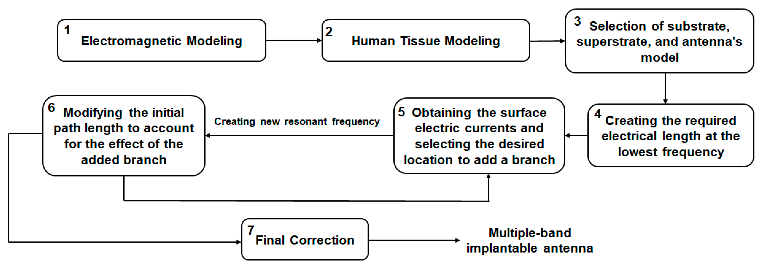
2.1. Simulation Models
2.2. Antenna I
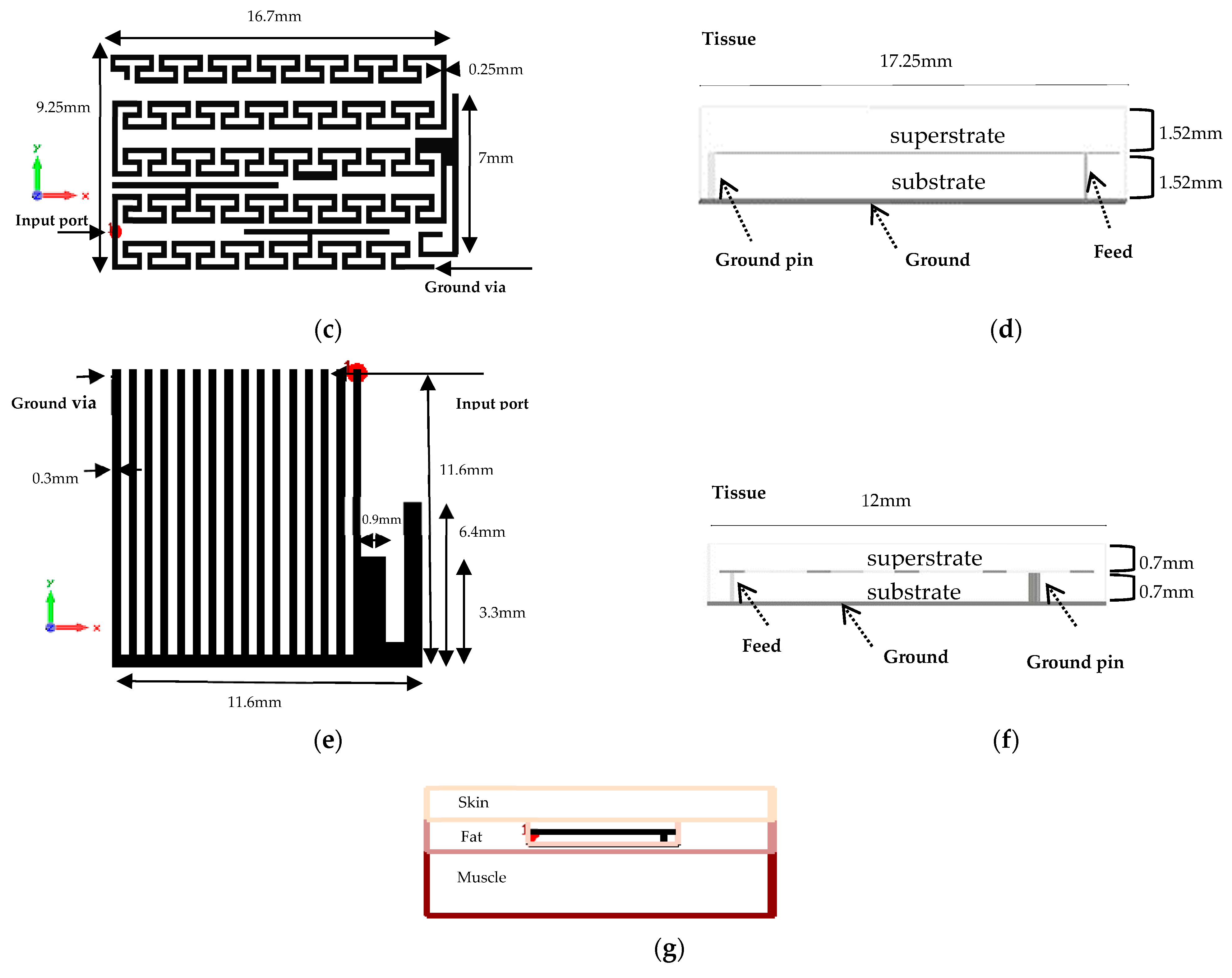
2.3. Antenna II
2.4. Antenna III
3. Results
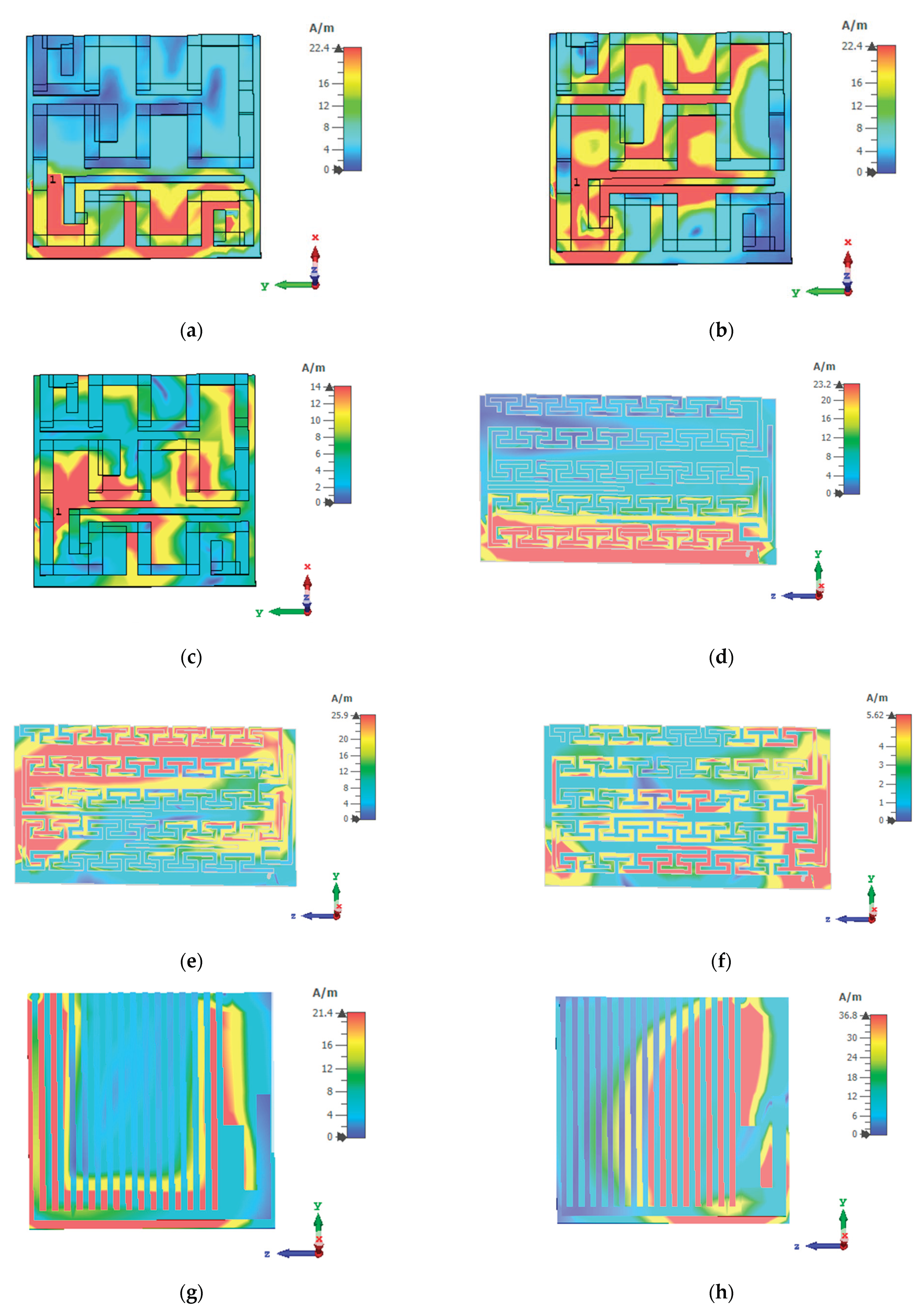
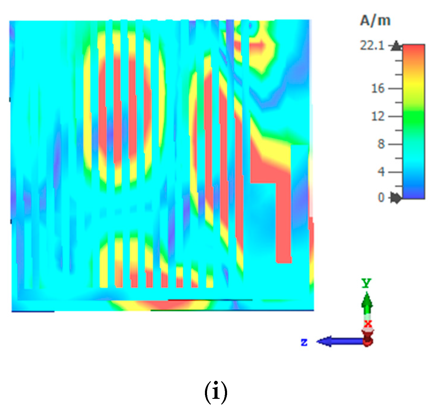
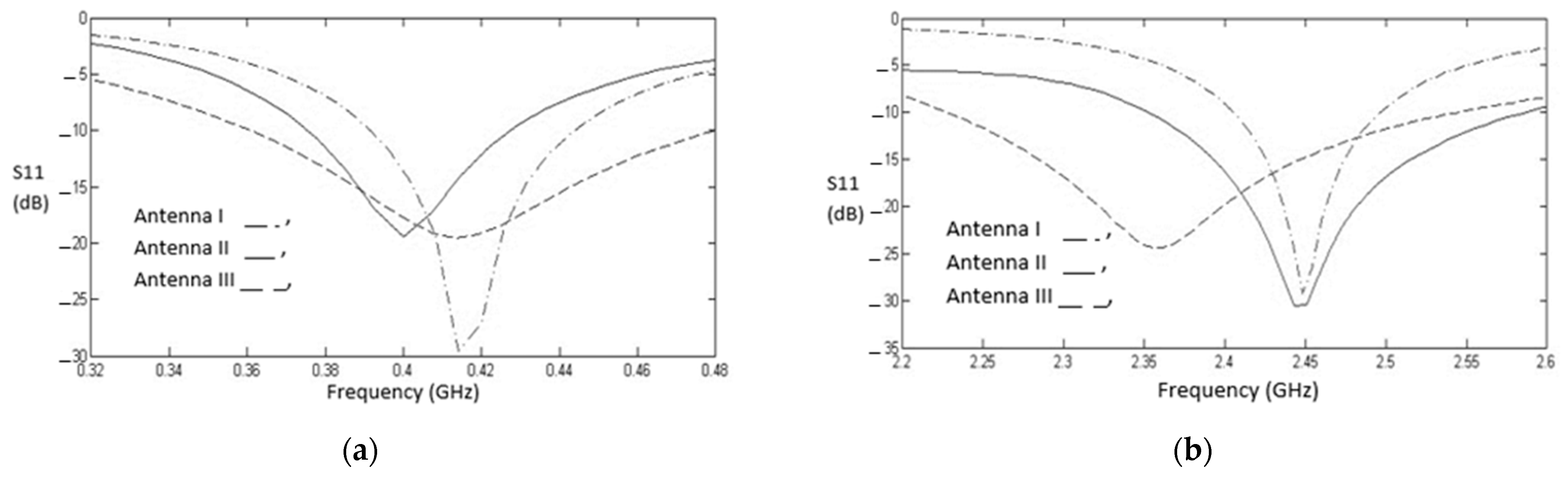
3.1. Design Characteristics

| Antennas | Center Frequency (GHz) | BW (MHz) | Gain (dB) | Center Frequency (GHz) | BW (MHz) | Gain (dB) | Center Frequency (GHz) | BW (MHz) | Gain (dB) | Dimensions |
|---|---|---|---|---|---|---|---|---|---|---|
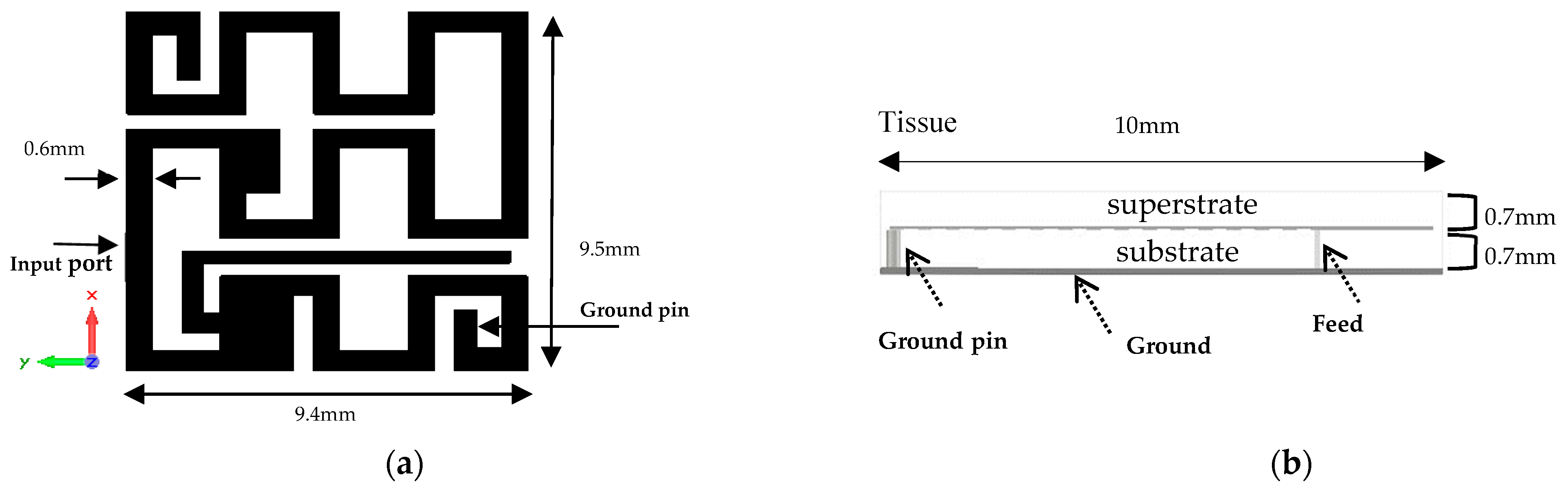
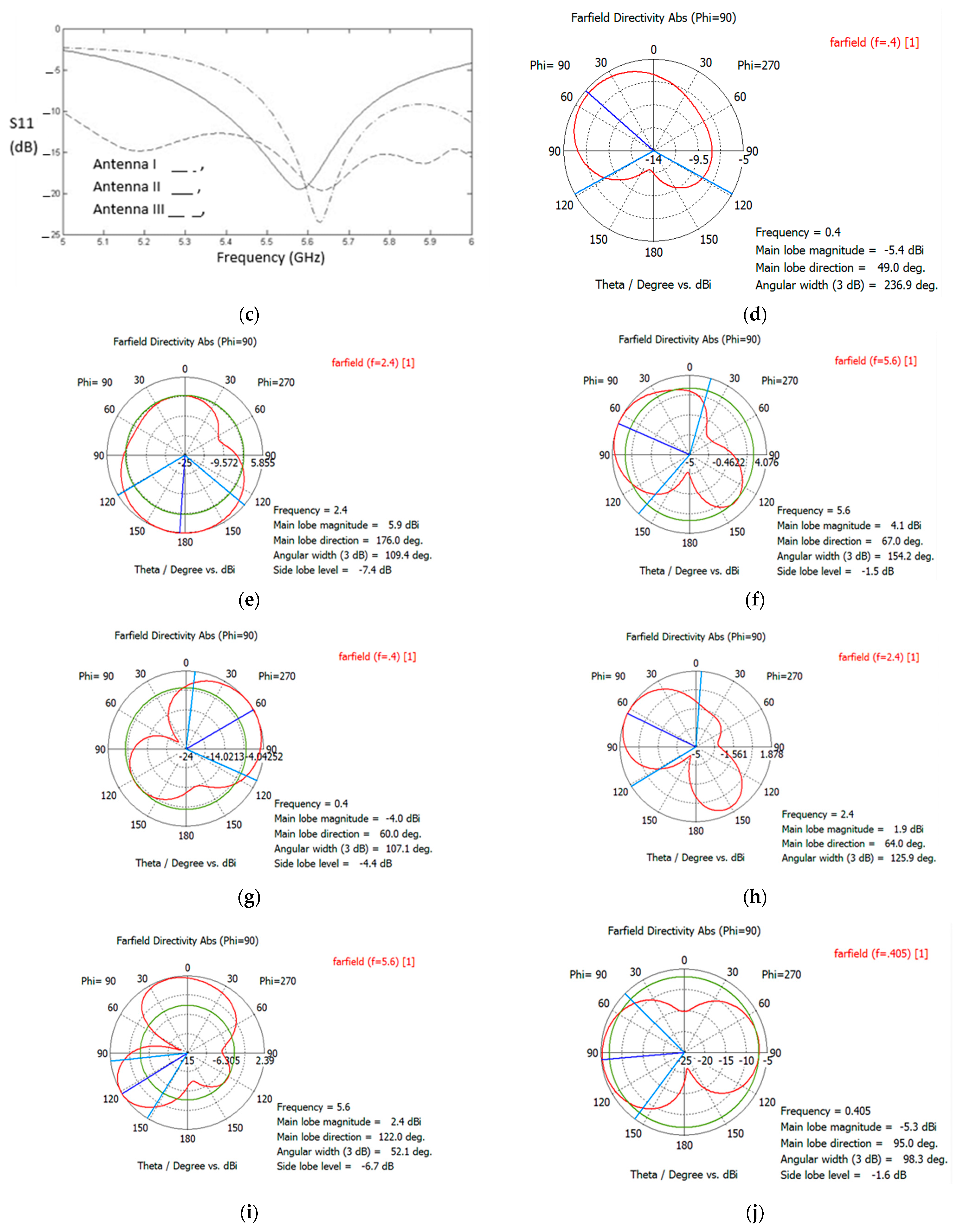
| Antenna I | 0.414 | 53 | −45 | 2.445 | 90 | −18 | 5.63 | 300 | −14 | 1.4 mm × 10 mm × 10 mm |
| Antenna II | 0.4 | 53 | −40 | 2.447 | 237 | −15 | 5.58 | 350 | −13.5 | 3.04 mm × 10 mm × 17.25 mm |
| Antenna III | 0.412 | 120 | −35 | 2.356 | 320 | −10 | 5.63 | 1200 | −16 | 1.4 mm × 12 mm × 12 mm |
| Sample [33] | 0.396 | 38.7 | −39 | 2.43 | 69.2 | −22 | - | - | - | 0.65 mm × 7.6 mm × 7.6 mm |
| Sample [34] | 0.404 | 30 | −36.7 | 2.48 | 168 | −27.1 | - | - | - | 1.27 mm × 22 mm × 23 mm |
| Sample [35] | - | - | - | 2.46 | 80 | −25 | - | - | - | 0.5 mm × 10 mm × 10 mm |
| Sample [36] | - | - | - | 0.9 | 32 | −29 | - | - | - | 1.27 mm × 15 mm × 15 mm |
| Sample [37] | 0.479 | 49 | −34.9 | - | - | - | - | - | - | 1.27 mm × 23 mm × 12.7 mm |
| Sample [38] | 0.402 | 23 | −46.2 | - | - | - | - | - | - | 1.9 mm × 16.4 mm × 19 mm |
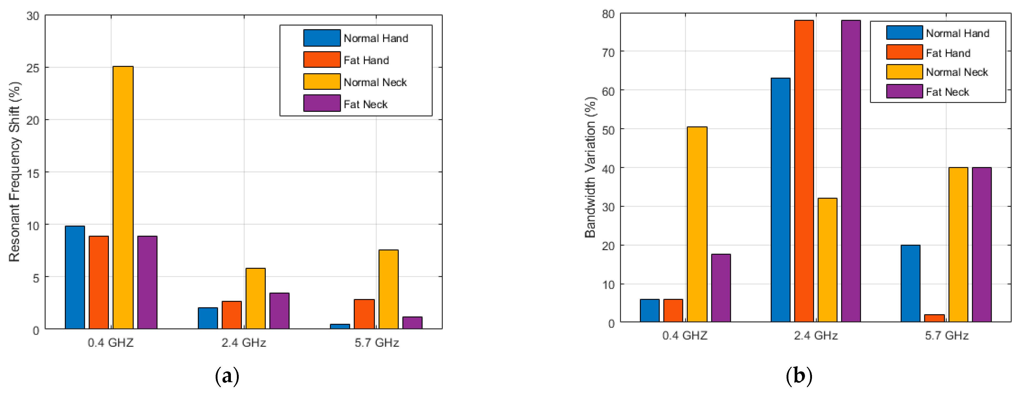
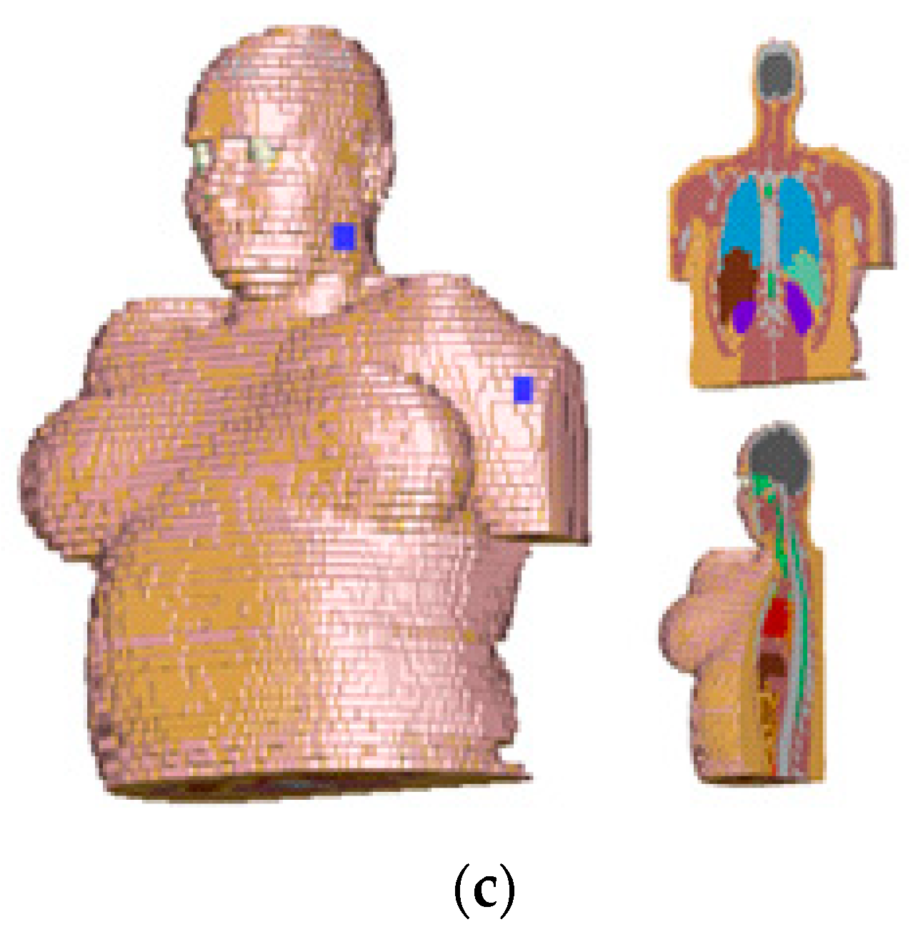
3.2. Effects of Body Tissue and Body Types
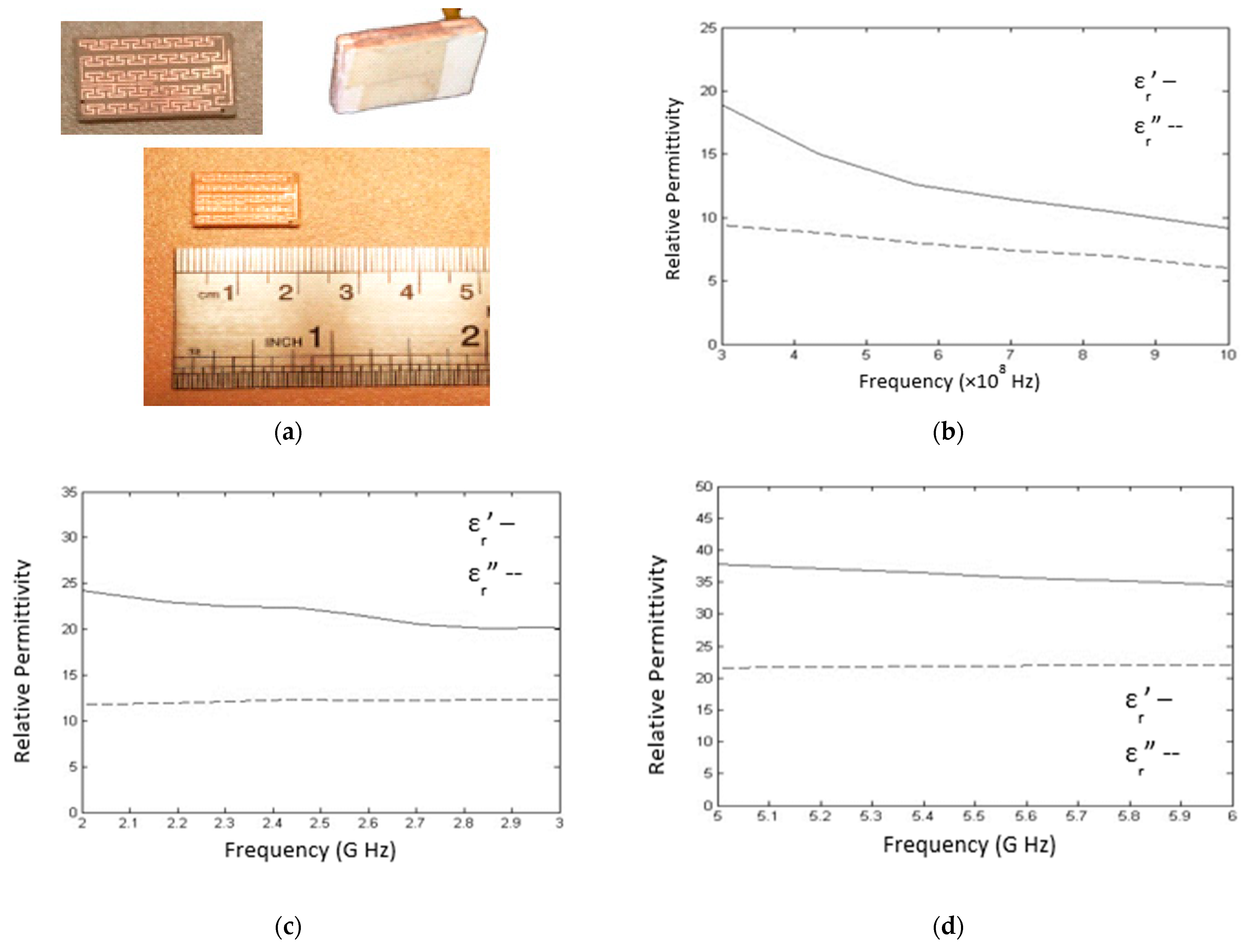
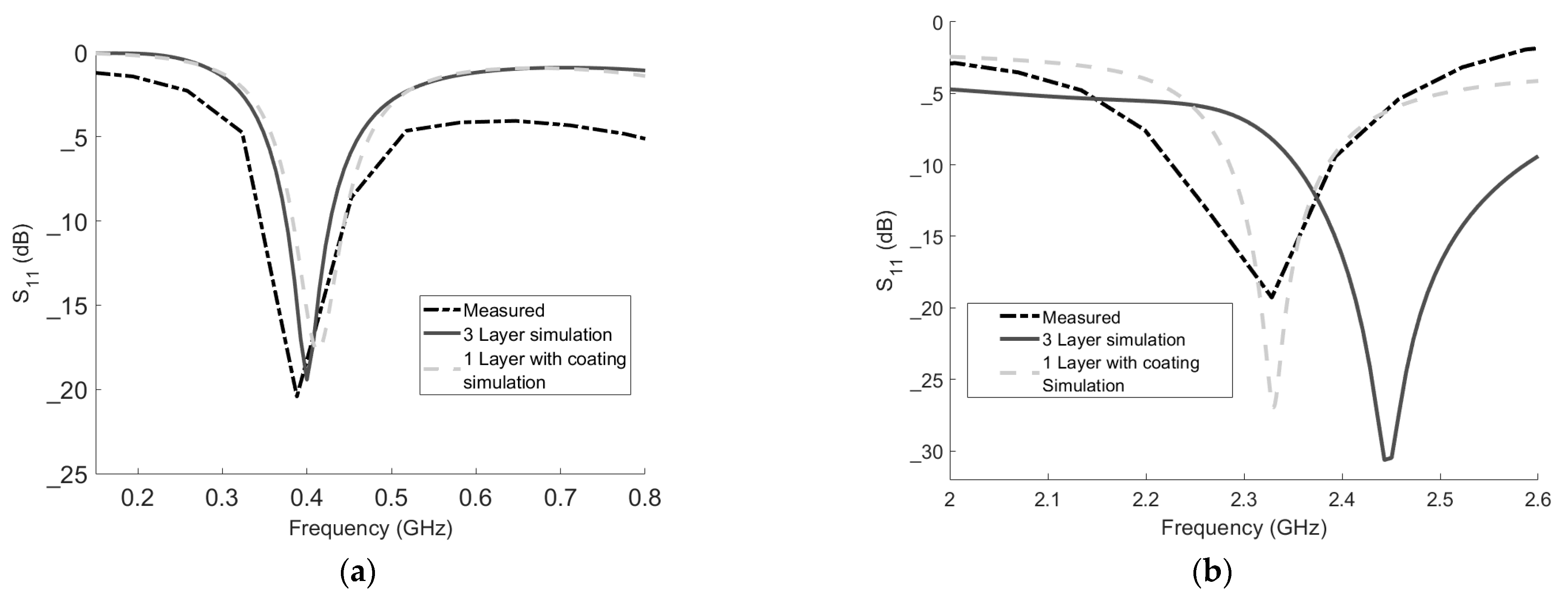
3.3. Mesaurements
4. Discussion and Conclusions
Author Contributions
Funding
Institutional Review Board Statement
Informed Consent Statement
Data Availability Statement
Conflicts of Interest
References
- Kim, J.; Samii, Y.R. Implanted Antennas Inside a Human Body: Simulations, Designs, and Characterizations. IEEE Trans. Microw. Theory Technol. 2004, 52, 1934–1943. [Google Scholar] [CrossRef]
- Murphy, O.H.; McLeod, C.N.; Navaratnarajah, M.; Yacoub, M.; Toumazou, C. A Pseudo-Normal-Mode Helical Antenna for Use With Deeply Implanted Wireless Sensors. IEEE Trans. Antenna Propag. 2012, 60, 1135–1139. [Google Scholar] [CrossRef]
- Xia, W.; Saito, K.; Takahashi, M.; Ito, K. Performances of an Implanted Cavity Slot Antenna Embedded in the Human Arm. IEEE Trans. Microw. Theory Technol. 2009, 57, 894–899. [Google Scholar] [CrossRef]
- Liu, W.C.; Yeh, F.M.; Ghavami, M. Miniaturized Implantable Broadband Antenna for Biotelemetry Communication. Microw. Opt. Technol. Lett. 2008, 50, 2407–2409. [Google Scholar] [CrossRef]
- Chow, E.Y.; Chlebowski, A.L.; Chakraborty, S.; Chappell, W.J.; Irazoqui, P.P. Fully Wireless Implantable Cardiovascular Pressure Monitor Integrated with a Medical Stent. IEEE Trans. Biomed. Eng. 2010, 57, 1487–1496. [Google Scholar] [CrossRef]
- Tikka, A.C.; Faulkner, M.; Al-Sarawi, S.F. Secure Wireless Actuation of an Implanted Microvalve for Drug Delivery Applications. Smart Mater. Struct. 2011, 20, 105011. [Google Scholar] [CrossRef]
- Joo, H.; Lee, Y.; Kim, J.; Yoo, J.S.; Yoo, S.; Kim, S.; Arya, A.K.; Kim, S.; Choi, S.H.; Lu, N.; et al. Soft Implantable Drug Delivery Device Integrated Wirelessly with Wearable Devices to Treat Fatal Seizures. Sci. Adv. 2021, 7, eabd4639. [Google Scholar] [CrossRef]
- Mason, P.A.; Murphy, M.R.; Petersen, R.C. IEEE SCC-28 Standards; IEEE EMF Health & Safety Standards. IEEE: Piscataway, NJ, USA, 2019.
- Kiourti, A.; Nikita, K.S. Implantable antennas: A tutorial on design, fabrication, and in vivo testing. IEEE Microw. Mag. 2014, 15, 77–91. [Google Scholar]
- Bonefačić, D.; Bartolić, J. Small Antennas: Miniaturization Techniques and Applications. Automatika 2012, 53, 20–30. [Google Scholar] [CrossRef] [Green Version]
- Wheeler, A. Fundamental Limitations of Small Antennas. Proc. IRE 1947, 35, 1479–1484. [Google Scholar] [CrossRef]
- Chu, J. Physical Limitation on Omni-Directional Antennas. J. Appl. Phys. 1948, 19, 1163–1175. [Google Scholar] [CrossRef] [Green Version]
- Merli, F.; Bolomey, L.; Meurville, E.; Skrivervik, A.K. Implanted Antenna for Biomedical Applications. In Proceedings of the 2008 IEEE Antennas and Propagation Society International Symposium, San Diego, CA, USA, 5–11 July 2008; pp. 1–4. [Google Scholar]
- Kiourti, A.; Nikita, K.S. Miniature Scalp–Implantable Antennas for Telemetry in the MICS and ISM Bands: Design, Safety Considerations and Link Budget Analysis. IEEE Trans. Antennas Propag. 2012, 60, 3568–3575. [Google Scholar] [CrossRef]
- Kiourti, A.; Christopoulou, M.; Nikita, K.S. Performance of A Novel Miniature Antenna Implanted in The Human Head for Wireless Biotelemetry. In Proceedings of the 2011 IEEE International Symposium on Antennas and Propagation, Spokane, WA, USA, 3–8 July 2011; pp. 392–395. [Google Scholar]
- Huang, F.J.; Lee, C.M.; Chang, C.L.; Chen, L.K.; Yo, T.C.; Luo, C.H. Rectenna Application of Miniaturized Implantable Antenna Design for Triple-Band Biotelemetry Communication. IEEE Trans. Antenna Propag. 2011, 59, 2646–2653. [Google Scholar] [CrossRef]
- Li, H.; Guo, Y.-X.; Liu, C.; Xiao, S.; Li, L. A Miniature-Implantable Antenna for MedRadio-Band Biomedical Telemetry. IEEE Antennas Wirel. Propag. Lett. 2015, 14, 1176–1179. [Google Scholar] [CrossRef]
- Kumar, P.; Ali, T.; Pai, M.M.M. Electromagnetic Metamaterials: A New Paradigm of Antenna Design. IEEE Access 2021, 9, 18722–18751. [Google Scholar] [CrossRef]
- Alibakhshikenari, M.; Virdee, B.S.; Azpilicueta, L.; Naser-Moghadasi, M.; Akinsolu, M.O.; See, C.H.; Liu, B.; Abd-Alhameed, R.A.; Falcone, F.; Huynen, I.; et al. A Comprehensive Survey of Metamaterial Transmission-Line Based Antennas: Design, Challenges, and Applications. IEEE Access 2020, 8, 144778–144808. [Google Scholar] [CrossRef]
- Palmeri, R.; Bevacqua, M.T.; Morabito, A.F.; Isernia, T. Design of Artificial-Material-Based Antennas Using Inverse Scattering Techniques. IEEE Trans. Antennas Propag. 2018, 66, 7076–7090. [Google Scholar] [CrossRef]
- Althuwayb, A.A. Enhanced Radiation Gain and Efficiency of a Metamaterial-Inspired Wideband Microstrip Antenna Using Substrate Integrated Waveguide Technology for sub-6 GHz Wireless Communication Systems. Microw. Opt. Technol. Lett. 2021, 63, 1892–1898. [Google Scholar] [CrossRef]
- Fallahpour, M.; Zoughi, R. Antenna Miniaturization Techniques: A Review of Topology- and Material-Based Methods. IEEE Antennas Propag Mag 2018, 60, 38–50. [Google Scholar] [CrossRef]
- Hashemi, S.; Rashed-Mohassel, J. Design and Miniaturization of Dual Band Implantable Antennas. Biocybern. Biomed. Eng. 2018, 38, 868–876. [Google Scholar] [CrossRef]
- Nösslinger, H.; Mair, E.; Toplak, H.; Hörmann-Wallner, M. Measuring subcutaneous fat thickness using skinfold calipers vs. high-resolution B-scan ultrasonography in healthy volunteers: A pilot study. Clin. Nutr. Open Sci. 2022, 41, 19–32. [Google Scholar] [CrossRef]
- Augustine, R. Electromagnetic Modeling of Human Tissues and Its Application on the Interaction Between Antenna and Human Body in the BAN Context. Ph.D. Thesis, Paris-Est University, Créteil, France, 2009. [Google Scholar]
- Volakis, J.L.; Chen, C.C. Small Antennas Miniaturization Techniques and Applications. In McGraw Hill; McGraw Hill: New York, NJ, USA, 2010; Chapter 3. [Google Scholar]
- Kraus, J.D.; Marhefka, R.J. Antennas for All Applications, 3rd ed.; McGraw Hill: New York, NJ, USA, 1988. [Google Scholar]
- Hansen, R.C. Electrically Small, Superdirective, and Superconducting Antennas; John Wiley & Sons, Inc.: Hoboken, NJ, USA, 2006. [Google Scholar]
- Rashed, J.; Tai, C.T. A New Class of Resonant Antennas. IEEE Trans. Antenna Propag. 1991, 39, 1428–1430. [Google Scholar] [CrossRef]
- Yongle, W.; Liao, M.; Su, M.; Liu, Y. A Novel Differential Dual-Frequency Patch Antenna with Bandwidth Enhancement. Electromagnetics 2015, 35, 40–48. [Google Scholar]
- Xu, L.; Guo, Y.; Wu, W. Miniaturized Dual-Band Antenna for Implantable Wireless Communications. IEEE Antennas Wirel. Propag. Lett. 2014, 13, 1160–1163. [Google Scholar]
- Zhu, D.; Guo, Y.X.; Je, M.; Kwong, D.L. Design and in vitro test of differentially fed dual-band implantable antenna operating at MICS and ISM bands. IEEE Trans. Antenna Propag. 2014, 62, 2430–2439. [Google Scholar]
- Konstantinos, K. Konstantinos Dual Band Implantable Antenna for Biomedical Telemetry Applications. In Proceedings of the International Conference on Radar, Antenna, Microwave, Electronics, and Telecommunications (ICRAMET), Tangerang, Indonesia, 18–20 November 2020; pp. 253–256. [Google Scholar]
- Liu, Y.; Chen, Y.; Lin, H.; Juwono, F.H. A Novel Differentially Fed Compact Dual-Band Implantable Antenna for Biotelemetry Applications. IEEE Antennas Wirel. Propag. Lett. 2016, 15, 1791–1794. [Google Scholar] [CrossRef]
- Rana, B.; Shim, J.Y.; Chung, J.Y. An implantable antenna with broadside radiation for a brain–machine interface. IEEE Sens. J. 2019, 19, 9200–9205. [Google Scholar] [CrossRef]
- Liu, C.; Zhang, Y.; Liu, X. Circularly Polarized Implantable Antenna for 915 MHz ISM-Band Far-Field Wireless Power Transmission. IEEE Antennas Wirel. Propag. Lett. 2018, 17, 373–376. [Google Scholar] [CrossRef]
- Li, R.; Li, B.; Du, G.; Sun, X.; Sun, H. A Compact Broadband Antenna with Dual-Resonance for Implantable Devices. Micromachines 2019, 10, 59. [Google Scholar] [CrossRef] [PubMed] [Green Version]
- Jain, L.; Singh, R.; Rawat, S.; Ray, K. Stacked Arrangement of Meandered Patches for Biomedical Applications. Int. J. Syst. Assur. Eng. Manag. 2018, 9, 139–146. [Google Scholar] [CrossRef]
- Venkatesh, M.S.; Raghavan, G.S.V. An Overview of Dielectric Properties Measuring Techniques. Can. Biosyst. Eng. 2005, 47, 15–30. [Google Scholar]
- Berube, D.; Ghannouchi, F.M.; Savard, P. A Comparative Study of Four Open-Ended Coaxial Probe Models for Permittivity Measurements of Lossy Dielectric/Biological Materials at Microwave Frequencies. Trans. Microw. Theory Techn. 1996, 44, 10. [Google Scholar] [CrossRef]
- Lazebnik1, M.; Madsen, E.L.; Frank, G.R.; Hagness, S.C. Tissue-mimicking Phantom Materials for Narrowband and Ultra Wideband Microwave Applications. Phys. Med. Biol. 2005, 50, 4245–4258. [Google Scholar] [CrossRef] [PubMed]
- Porter, E.; Fakhoury, J.; Oprisor, R.; Coates, M.; Popović, M. Improved Tissue Phantoms for Experimental Validation of Microwave Breast Cancer Detection. In Proceedings of the European Conference on Antennas and Propagation, Barcelona, Spain, 12–16 April 2010. [Google Scholar]


| 400 MHz Band SAR 1 g (W/Kg) | 2.4 GHz Band SAR 1 g (W/Kg) | 5.7 GHz Band SAR 1 g (W/Kg) | |
|---|---|---|---|
| Antenna I | 494 | 344 | 320 |
| Antenna II | 308 | 292 | 328 |
| Antenna III | 94 | 296 | 572 |
| Volume Percentage | N-Butanol 96% | Propanol 99% | Purified Water TDS = 5 | Salt | Frequency Band |
|---|---|---|---|---|---|
| Phantom 1 | 49 | 49 | 1.9 | 0.1 | 400 MHz |
| Phantom 2 | 31 | 31 | 37.7 | 0.3 | 2.4 GHz |
| Phantom 3 | 12.5 | 12.5 | 74.35 | 0.15 | 5.6 GHz |
Publisher’s Note: MDPI stays neutral with regard to jurisdictional claims in published maps and institutional affiliations. |
© 2022 by the authors. Licensee MDPI, Basel, Switzerland. This article is an open access article distributed under the terms and conditions of the Creative Commons Attribution (CC BY) license (https://creativecommons.org/licenses/by/4.0/).
Share and Cite
Shahverdi, K.; Hashemi, S.; Sarafan, S.; Cao, H. Triple-Band Implantable Antenna Design for Biotelemetry Applications in MICS/ISM/Wi-Fi/Bluetooth Bands. Technologies 2022, 10, 91. https://doi.org/10.3390/technologies10040091
Shahverdi K, Hashemi S, Sarafan S, Cao H. Triple-Band Implantable Antenna Design for Biotelemetry Applications in MICS/ISM/Wi-Fi/Bluetooth Bands. Technologies. 2022; 10(4):91. https://doi.org/10.3390/technologies10040091
Chicago/Turabian StyleShahverdi, Kaveh, Soheil Hashemi, Sadaf Sarafan, and Hung Cao. 2022. "Triple-Band Implantable Antenna Design for Biotelemetry Applications in MICS/ISM/Wi-Fi/Bluetooth Bands" Technologies 10, no. 4: 91. https://doi.org/10.3390/technologies10040091
APA StyleShahverdi, K., Hashemi, S., Sarafan, S., & Cao, H. (2022). Triple-Band Implantable Antenna Design for Biotelemetry Applications in MICS/ISM/Wi-Fi/Bluetooth Bands. Technologies, 10(4), 91. https://doi.org/10.3390/technologies10040091