Article

Triple-Band Implantable Antenna Design for Biotelemetry Applications in MICS/ISM/Wi-Fi/Bluetooth Bands

1
Department of Electrical Engineering and Computer Science, University of California Irvine, Irvine, CA 92697, USA
2
School of Electrical Engineering, Iran University of Science and Technology, Tehran 1684613114, Iran
*
Author to whom correspondence should be addressed.
Technologies 2022, 10(4), 91; https://doi.org/10.3390/technologies10040091
Submission received: 7 July 2022 / Revised: 27 July 2022 / Accepted: 2 August 2022 / Published: 4 August 2022
(This article belongs to the Special Issue Mobile Computing, Wireless Networks & Security)

Abstract

:
Our objective is to design triple-band implantable antennas with wide bandwidths and appropriate sizes for biomedical applications. The targeted design frequencies are 400 MHz, 2.4 GHz, and the new Wi-Fi band of 5.7 GHz. Three triple-band antennas with bandwidth improvements are presented to insure all-time data connection. The proposed triple-band implantable antennas benefit from combining long-distance data transfer at lower frequency bands and a higher effective bandwidth, and high-speed communications at higher frequency bands, which will have flexibility for a variety of applications. A comprehensive explanation of the design procedure to achieve multiple-band implantable antennas is provided. Furthermore, miniaturization techniques are utilized to design antennas in compact sizes suitable for biomedical applications. In this paper, three-layer structures including skin, fat, and muscle are used for the designs, then antennas are placed in the chest, neck, head, and hand of different human voxels to compare antennas’ performance. Additionally, normal and overweight human effects on antenna performance were compared. Antennas have 2 to 6 dBi directivity for telemetry usage, and they are designed to satisfy the absorption limit for the human body to keep the Specific Absorption Rate (SAR) averaged over 1 g of tissue less than 1.6 W/kg and over 10 g of tissue less than 2 W/kg, according to IEEE standard. The antennas include fractal, meandered, and comb types with sizes of 1.4 mm × 10 mm × 10 mm, 3.04 mm × 10 mm × 17.25 mm, and 1.4 mm × 12 mm × 12 mm, respectively. The designed antenna showed an impedance bandwidth of 53 MHz to 120 MHz, 90 MHz to 320 MHz, and 300 MHz to 1200 MHz at the three bands. The meandered antenna was selected for validation of simulations, and its S parameters were measured in the equivalent liquid phantom of body tissues.

1. Introduction

In recent years, novel medical devices, such as wearables and patches, have been receiving a lot of attention in the field of biomedical research and the healthcare industry, providing solutions to a host of applications. Especially, the current global COVID-19 pandemic has led to a critical demand for person-centered healthcare instead of the conventional hospital-centered manner to reduce unnecessary contact as well as to relieve the burden on the healthcare system. The possibility of collecting vital data from a body and reprogramming in-body sets through wireless communications made implantable devices unique. Implantable antennas have been discussed since 2004, and they have reduced the need for further surgeries [1,2,3,4]. These wireless implantable products are widely used for clinical diagnosis and treatment applications, such as implantable medicine, nerve stimulation, and reprogramming of pacemakers or drug delivery, without the need for multiple surgeries [5,6,7]. To design implantable antennas, many parameters should be considered, including specific absorption rate (SAR) [8], dimension limits, biocompatibility, and sufficient bandwidth.
For the safety of the human body, the maximum power transmitted by the implantable antenna should not exceed certain levels that are imposed by regulations to avoid adverse health effects by electromagnetic emissions. For this purpose, the IEEE C95.1-1999 standard restricts specific absorption rate (SAR) averaged over 1 g of tissue to be less than 1.6 W/kg [8]. SAR is primarily dominated by electric fields in the tissue, and it is given by the following formula:
SAR = σ r E r 2   ρ r d r  
where σ r is the conductivity of the tissue, ρ r is the mass density of the tissue, and E r is the rms electric field. Therefore, in the design of implantable antenna, the maximum averaged E-field in the tissue should be kept low, while increasing BW, miniaturizing the dimensions, and improving other parameters. To determine the maximum allowable input power for an implantable antenna, maximum SAR averaged over 1 g of tissue is typically calculated first for 1 W of input power to the antenna and then maximum allowable input power is calculated to satisfy the maximum SAR of 1.6 W/kg limit in the human body. Consequently, implantable antennas with a lower SAR can benefit from using a higher allowable input power.
Implantable antennas also need to be biocompatible with the host body to ensure patient safety and to also prevent rejection of the implant. Specifically, the human body is conductive, and a short-circuit can be caused if the implantable antenna is not properly isolated from the human body. There are three methods commonly used to approach biocompatibility in implantable antennas: (1) Use of biocompatible substrate or superstrate, which is fabricated in the antenna’s structure; and (2) encapsulation, which is achieved by covering the antenna in an insulating dielectric material with low loss. For each of these methods, the radiation pattern, SAR, BW, gain, and other parameters of the antenna need to be studied after the addition of the biocompatible material to ensure that performance metrics are met [9].
Antennas’ performance parameters are strongly related to the dimension of the antenna [10,11,12]. The physical dimension of the antenna determines the current distribution over the antenna’s structure and consequently affects radiation pattern, input impedance, and bandwidth. In order to have appropriate current distribution with constructive radiation and a good performance, the antenna usually needs to be at resonance and has its size comparable to the wavelength or quarter wavelength, which means the implantable antennas need to be quite large at MICS (402–405 MHz) and ISM (902–928 MHz, 2.4–2.4835 GHz, and 5.725–5.825 GHz) bands. Therefore, effective miniaturization techniques to reduce the antenna’s dimensions without adversely affecting the antennas performance parameters, such as radiation, gain, and bandwidth, are critical and vital to realize practical and portable implantable antennas.
Bandwidth is also another parameter in the design of implantable antennas. Since the electromagnetic properties of human tissues are variable from person to person, the resonant frequency of antennas when implanted in different individuals may shift and affect the impedance matching of the antenna. Therefore, a wider bandwidth (BW) in implantable antennas is desirable to ameliorate this issue. In [13,14,15,16,17], some implantable antennas are reported with a lower than 50 MHz BW in each frequency band. Obviously, narrow BW is one of the disadvantages in these designs. Here, we aim to design our antennas smaller than others with a triple band, thus providing larger bandwidths.
Another factor in the design procedure of the antenna is the selection of the frequency bands. These bands usually include one or two of the 402 to 405 MHz, 902–928 MHz, and 2.4 to 2.485 GHz bands. The Medical Implant Communications Service (MICS) (402–405 MHz) band is used conventionally for biomedical applications. The Industrial, Scientific, and Medical (ISM) (902–928 MHz, 2.4–2.4835 GHz, and 5.725–5.825 GHz) band is also used for implantable antenna applications. Additionally, the ubiquitous adaption of high-speed communications in medical applications has resulted in a constantly growing demand for high-frequency antennas, with more effective data transmission. As such, we have developed novel triple-band antennas to take advantage of high-speed communications and long-distance data transmission together in one set. Lower frequencies are more desirable for long-distance communications since the wave propagation has less attenuation along the path and high frequencies are more suitable for high-speed communications since they provide a higher effective BW. Therefore, by designing the antennas to operate at 400 MHz from MICS band and 2.4 GHz and 5.7 GHz from ISM bands, better implantable antennas with flexibility for a variety of applications have been achieved. Furthermore, due to the popularity of the Internet of Things (IoT) in daily usage, the proposed antennas are designed at 5.7 GHz band to support both Bluetooth and Wi-Fi bands in addition to the ISM band.

2. Materials and Methods

Consumer electronics and communications advancements have been continuously demanding for an antenna with a more compact design, higher bandwidth, and other performance metric improvements. Numerous antenna miniaturization methods have been suggested to reduce the dimension and to enhance the bandwidth and radiation gain of the antenna. One of these techniques involves use of metamaterials in antennas. In this method, metamaterial structures made of periodic subwavelength unit cells are loaded onto the antenna [18,19]. These metamaterial structures show unique properties, such as negative permittivity or permeability, which can provide lower resonant frequency at similar antenna dimensions and hence help with antenna miniaturization and enhancement of the antenna’s bandwidth and gain. Several antenna bandwidth enhancement and miniaturization based on this method have been reported and demonstrated in the literature [20,21].
Another common antenna miniaturization techniques includes introducing space-filling curves to the antenna’s structure, which is utilized in this paper to design the proposed antenna. The idea is to use the available space efficiently to fit a larger radiating structure based on special mathematical curves. With this technique, the current distribution of the antenna should be well managed to constructively add at selected frequencies and angular directions. Otherwise, the radiation characteristics of the antenna, such as impedance matching, bandwidth, and gain, will degrade by miniaturization. Fractal antennas are one of the examples in this group in which an inherent geometrical self-similarity is used to achieve space-filling structures [22]. The Antenna I design is based on fractal structures, which uses Hilbert curves. Meander antennas are another example in this miniaturization group in which the structure of the antenna is miniaturized by introducing bendings and curves to the antenna’s geometry [22]. The Antenna II design is based on the meander structure. It can be seen in the Results section that meander structures are more successful in maintaining the radiation characteristics of the antenna compared to fractal antennas. Overall, adding more curves to the antenna’s structure comes at the expense of reducing radiation efficiency and bandwidth because some currents in the opposite phase are usually introduced in the structure of the antenna. Hence, a novel method previously proposed in [23] for the miniaturization of dual-band antennas is used here in the design of Antenna III for the design of a triple-band antenna. It can be seen in the Results section that this design is superior to the other two designs in terms of better radiation characteristics and smaller dimensions. In the design of the antennas, the inverted F method was used for feeding the antennas and tuning the input impedance to match the coaxial cable impedance. The planar inverted F antenna (PIFA) is a quarter-wavelength patch antenna with a shorting pin at the end. Since the antenna is shorted at the end, the current at the end of the patch antenna is no longer zero, and it has a path to flow in. In the planar inverted F antenna, the feed point is placed between the open and the short ends to adjust the input impedance of the antenna, while maintaining its high radiation efficiency.

2.1. Simulation Models

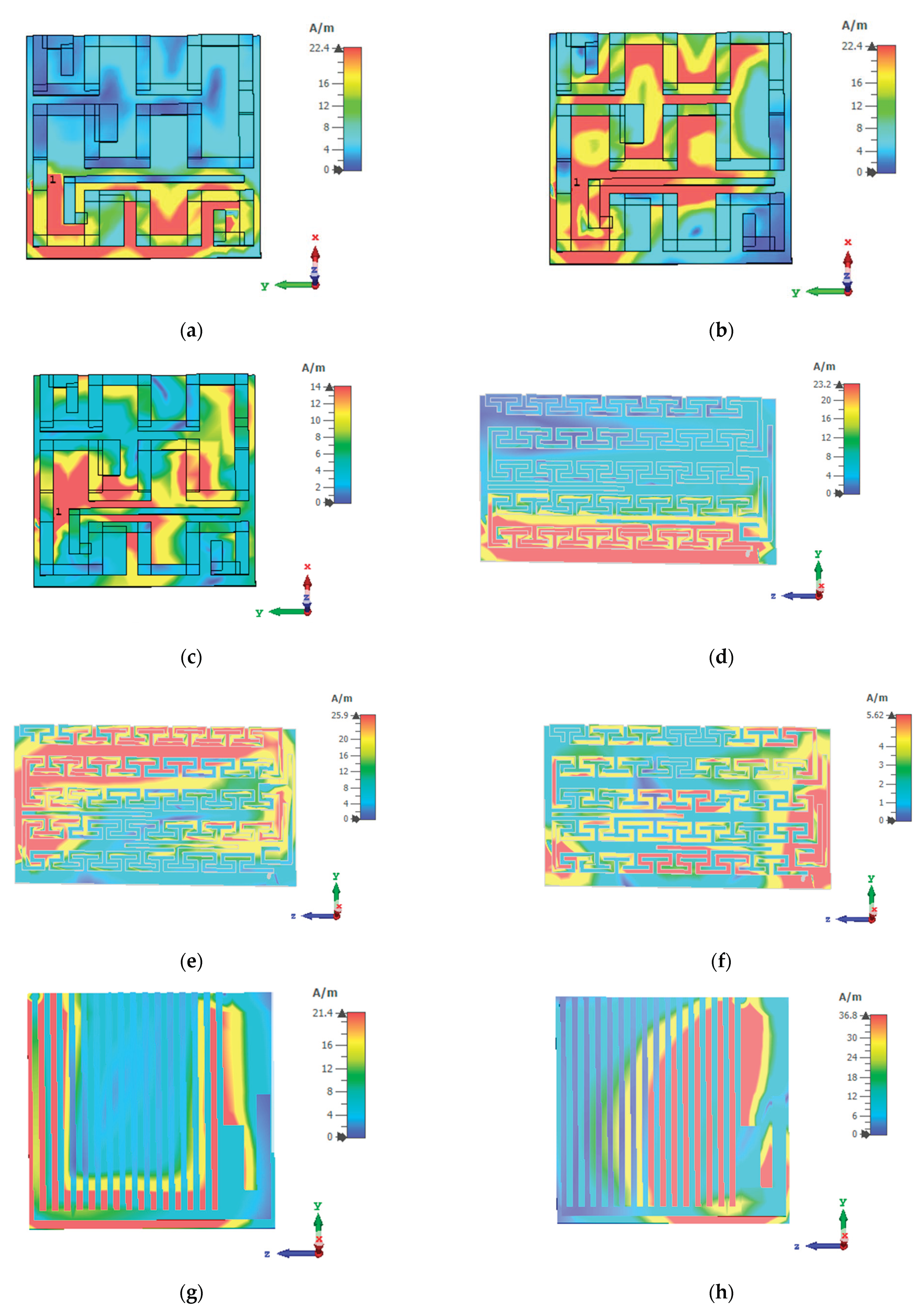
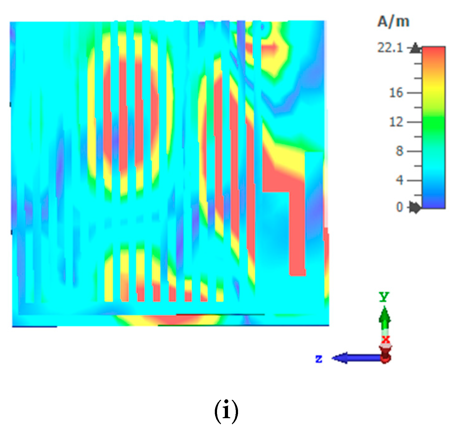
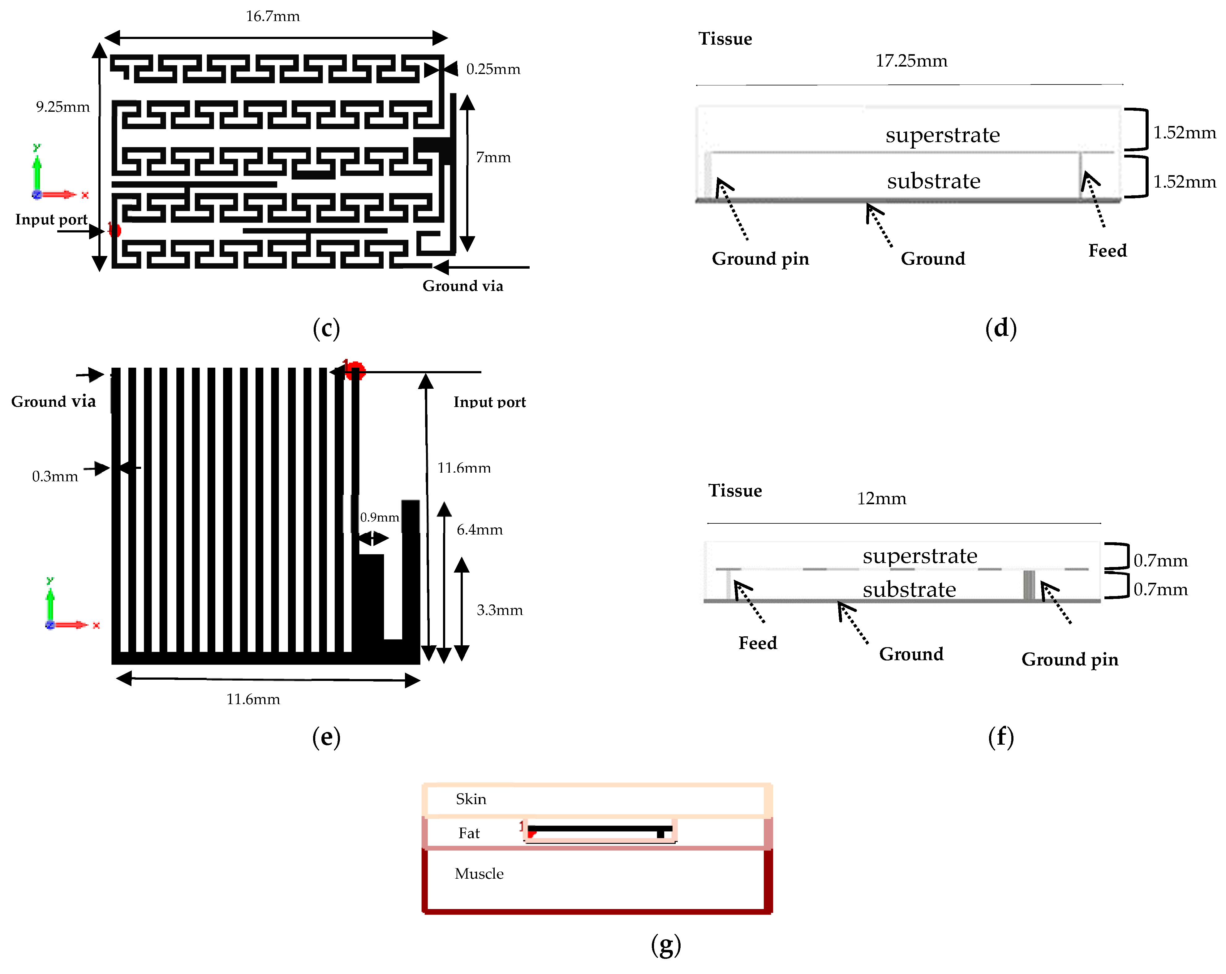
Our antennas are implantable in the fat tissue of the skin. Three-layer phantoms, including skin, fat, and muscle with thicknesses of 4 mm, 4 mm, and 8 mm, were chosen for the design. For the human body model, different thicknesses have been reported in the literature depending on the body type and also different body tissues. For example, for arm and chest, skin thicknesses of 2 mm and 5 mm have been reported. Similarly, depending on the body fat index of the human body, fat thicknesses between 2 mm to 15 mm have been measured [24]. In our modeling and simulation, in order to have results applicable to a broader range of cases, we selected average values of 4 mm and 4 mm for skin and fat thicknesses. For muscles thickness, since the simulation time increases with the increase of the model volume, our simulations showed that an 8 mm thickness can be appropriately assumed for the muscle thickness. Further increasing the muscle thickness did not show any significant changes in the simulation results. Therefore, by selecting a muscle thickness of 8 mm, accurate simulation results and lower simulation time have been accomplished. EM characteristics of these tissues are dispersive and thus dispersive models of these tissues in CST were used for the simulation. The dimensions of the phantom have been optimized for reliable results, and they are approximately 5 cm × 5 cm. A superstrate is used in addition to the substrate layer to avoid contact with conductive tissues. With the proper selection of feeding points, the input impedances of all designs are 50 Ohm. The substrate and the superstrate used in this paper are Rogers 3003 and Rogers 3210, with relative permittivities of 3 and 10.2 and loss tangents of 0.0013 and 0.0027, respectively [25]. Rogers 3210 is used in the design of Antenna I and III and Rogers 3003 is used in the design of Antenna II. In all designs, the first step is specifying the path for the first resonant frequency. The second and third resonances are added by introducing extra branches. To miniaturize the antennas, all of them benefit from the PIFA idea to reduce the size to half of ordinary designs because of ground via and λ/4 length instead of λ/2. Other methods used in antenna miniaturization are introduced in the following [26,27,28]. Structures and dimensions of the three designs can be seen in Figure 1 and Table 1, and the electrical surface current distribution of each antenna can be viewed in Figure 2.

2.2. Antenna I

In this design, the first order of the Hilbert method is used to miniaturize the antenna for the first resonant frequency. By adding more vertices to the geometry of the antenna and bending the antenna’s shape in a quasi-periodic pattern, we were able to miniaturize the antenna’s dimensions. The effective length of the antenna does not decrease, but the required area is smaller since the length of the antenna is distributed more evenly on the surface. Then, this idea was combined with the inverted F method so that the input impedance of the antenna could be tuned for the impedance matching by moving the location of the input port and also have the effective length of the antenna λ/4. After the main body and dimensions of the antenna are determined for 400 MHz resonance frequency and the current distribution is observed by the simulation, other branches are added to the high-current nodes of the antenna to achieve the other resonant frequencies at 2.45 GHz and 5.63 GHz bands. Adding the branches to the high-current nodes also increases the capacitance between the lines, which also helps to further decrease the antenna size to 1.4 mm × 10 mm × 10 mm.

2.3. Antenna II

The structure of this antenna is based on the meander geometry. In this design, similar to the previous design, the method of adding vertices and bending points to the path of the antenna is utilized. However, there is a significant difference in the implementation of this idea compared to the previous design; in this method, periodic units with an odd number of lines are used to reduce the occupied area by the antenna. As seen in Figure 1c, each periodic cell has three current paths; two forward-going paths and one backward-going path, which practically increases the effective length of the antenna three times in the same occupied area, with a minimal negative effect on the antenna’s radiation pattern and gain. This idea can be expanded to higher numbers of current paths in each periodic unit cell. However, it should be noted that the number of the current paths in each unit cell needs to be an odd number because when the forward-going and backward-going current paths with opposite directions are placed close to each other on the antenna’s structure, they can cancel each other’s radiation and decrease the gain. Therefore, by having an odd number of current paths in each unit cell, we will have one complete effective radiating current path, which has a minimal effect on the radiation and gain but the required area for the antenna is considerably decreased. Finally, the number of the antenna’s main branches, which is also periodic, needs to be an odd number as well for similar radiation consideration. As you can see in Figure 1, the number of main branches is 5 in Antenna II and 3 in Antenna I for this reason. Furthermore, the reason that Antenna II has more major current branches compared to Antenna I is that the substrate’s relative dielectric constant is 10.2 in Antenna I and 3 in Antenna II. Therefore, Antenna I needs less length to have the effective length of a quarter wavelength (λ/4) due to the higher dielectric constant of its substrate. It should also be noted that, in the design of Antenna II, having a lower substrate dielectric constant and a thicker substrate thickness can reduce the effective capacitance to the ground and consequently achieve a better radiation gain and bandwidth. At the end, similar to the previous design, after the main body and dimensions of the antenna are determined for 400 MHz resonance frequency, other branches are added to some of the high-current nodes to create quarter-wavelength current paths to obtain higher resonance frequencies at 2.4 GHZ and 5.7 GHz bands. Consequently, by using the T-shape branches, three resonant frequencies can be tuned almost independently. The inverted F method is also incorporated to tune the input impedance by changing the input port location. The use of periodic unit cells in this design helped to miniaturize the structure by approximately 40% and to reduce the dimensions of the antenna to 3.04 mm × 10 mm × 17.25 mm.

2.4. Antenna III

The miniaturization technique used for Antenna III is different from the Antenna I and II designs. In patch antennas, one effective way to reduce the antenna’s area and improve the bandwidth is to introduce slots in the structure of the antenna. In this method, by having slots and defects in the antenna’s shape, we can cause curves and bendings in the current paths and consequently have a smaller area, without the need to introduce vertices in the antenna’s structure itself. Additionally, by adding periodic slots in Antenna III, we have periodic capacitances between the adjacent branches, which decreases the resonance frequency and hence further reduces the area of the antenna. It is also worth noting that since there is no opposite going current paths in this design, miniaturization has the least negative effect on the radiation pattern. Finally, similar to the previous designs, the inverted F method is used to tune the input impedance, and additional branches at high-current nodes are introduced to achieve resonance frequencies of 2.4 GHz and 5.7 GHz bands. This configuration has the best BW among the three designs. Unlike the other geometries, in the comb antenna, the input port is located at the beginning of the structure. The dimensions are 1.4 mm × 12 mm × 12 mm.
Figure 2. Electrical surface current distribution of each antenna at resonant frequencies. (a) 400 MHz, (b) 2.4 GHz, (c) 5.7 GHz, (d) 400 MHz, (e) 2.4 GHz, (f) 5.7 GHz, (g) 400 MHz, (h) 2.4 GHz, and (i) 5.7 GHz.
Technologies 10 00091 g002aTechnologies 10 00091 g002b
The step-by-step process for designing a multiple-band implantable antenna is shown in Figure 3. In the next section, the results and performance of the mentioned implantable antennas in the equivalent phantom are compared [29].

3. Results

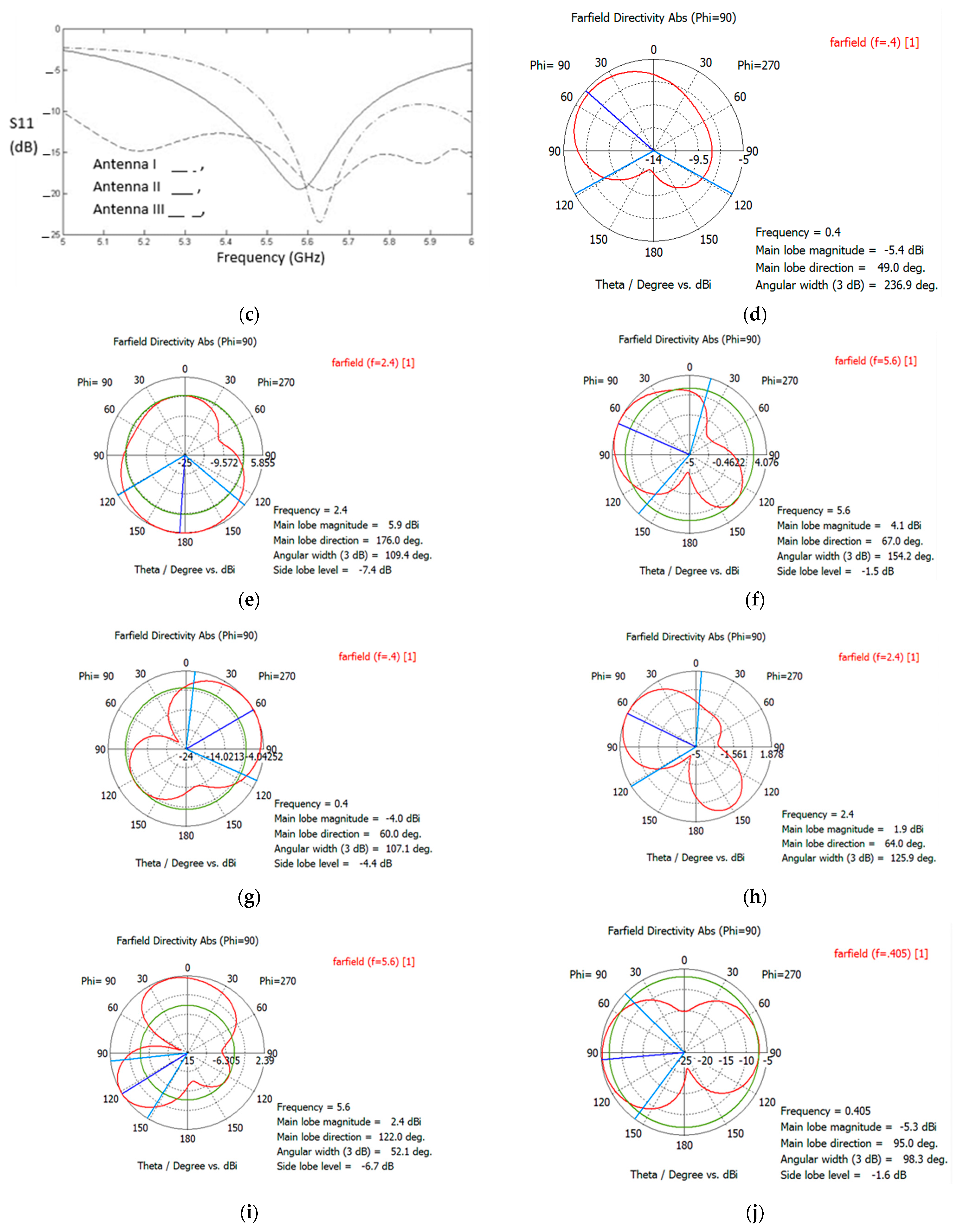
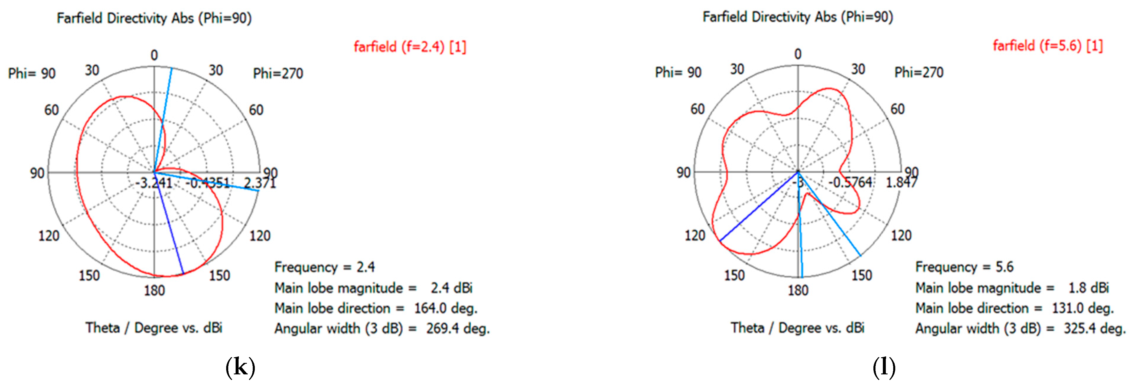
The S11 of implantable antennas at the three bands are shown in Figure 4a–c, and the center resonant frequency and BWs can be obtained from diagrams, which are indicated in Table 1. Patterns of the antennas versus ϴ at three bands are also observed in Figure 4d–l, which shows a sufficient pattern suitable for implantable applications. Other characteristics are presented in the following. It can be seen that the BW of the comb antenna is more than the other designs [30,31,32].

3.1. Design Characteristics

In Table 1, the center frequencies and other characteristics of the designs as well as some reported implantable antennas are presented. It is observed that the first and the third designs are smaller in size than most of the other samples. All designs have better BW in at least 2 bands of operation in comparison with other reported samples. Among our designs, the comb antenna has the best BW, and it can be used in all new Wi-Fi bands, including indoor, outdoor, and the 5 to 6 GHz range. Since samples are dual-band implantable antennas, some cells in the Table do not have entries.
Table 1. Comparison between the presented designs and other reported samples.
AntennasCenter Frequency (GHz)BW (MHz)Gain (dB)Center Frequency (GHz)BW (MHz)Gain (dB)Center Frequency (GHz)BW (MHz)Gain (dB)Dimensions
Antenna I0.41453−452.44590−185.63300−141.4 mm × 10 mm × 10 mm
Antenna II0.453−402.447237−155.58350−13.53.04 mm × 10 mm × 17.25 mm
Antenna III0.412120−352.356320−105.631200−161.4 mm × 12 mm × 12 mm
Sample [33]0.39638.7−392.4369.2−22---0.65 mm × 7.6 mm × 7.6 mm
Sample [34]0.40430−36.72.48168−27.1---1.27 mm × 22 mm × 23 mm
Sample [35]---2.4680−25---0.5 mm × 10 mm × 10 mm
Sample [36]---0.932−29---1.27 mm × 15 mm × 15 mm
Sample [37]0.47949−34.9------1.27 mm × 23 mm × 12.7 mm
Sample [38]0.40223−46.2------1.9 mm × 16.4 mm × 19 mm
SAR limit is another important criterion in implantable antennas for the safety concern of the human body. The IEEE standard [8] restricts the Specific Absorption Rate (SAR) averaged over 1 g of tissue is less than 1.6 W/kg and over 10 g of tissue is less than 2 W/kg. In our simulations, the peak SAR in 1 g of the tissue was less than 300 W/Kg for 0.5 W stimulation power in three antennas, therefore, to observe the SAR limits, the input power should not exceed 2.5 mW to preserve a SAR of less than 1.6 W/Kg. Calculated SAR from 1 w input power for all antennas are shown in Table 2. Since in implantable applications, the antenna is communicating with an indoor communication point, such as Wi-Fi, this input power is sufficient for the intended biotelemetry applications and the indoor communication ranges. For example, most Wi-Fi or Bluetooth transceivers can easily communicate with signal levels of −70 dbm to −80 dbm. Assuming an input power of 2.5 mw and an average antenna gain of −15 db at 2.4 GHz frequency band, we can have up to a 10 m to 25 m distance for effective indoor communication. For 400 MHz and 5.7 GHz bands, the available distance for effective communication will be, respectively, higher and lower than the 2.4 GHz band due to the quadratic relationship between the free-space path loss and the wavelength. At 400 MHz the antenna can communicate to further distances but at a lower data rate because of lower bandwidth.

3.2. Effects of Body Tissue and Body Types

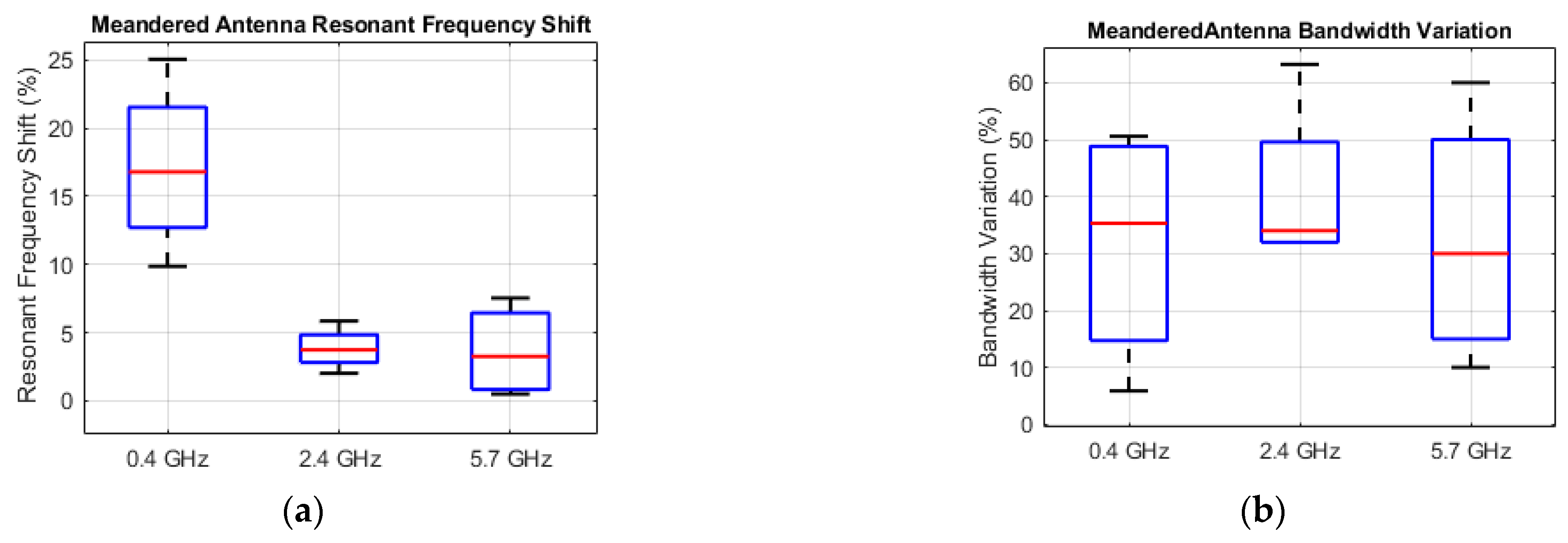
Since the comb and meander antennas showed a better performance, alteration in the performance of these antennas in different parts of the body was investigated. The percentage of the alteration of the resonant frequencies and bandwidth for the position placement of the antennas in the human voxel in comparison with the results of the antennas’ simulation in the three-layer phantom model is illustrated in Figure 5. Laura human voxel of CST was selected for this simulation. Figure 5a shows four different possible placements of the implantable antennas in the body including chest, neck, arm, and head. Due to different electrical properties and the nonhomogeneity of each part of the body, some changes in the performance of each antenna are expected. Figure 5c,d demonstrate the box plots of the variations in the resonant frequency and bandwidth of the comb and meander antennas at the three bands, when placed in the chest, neck, arm, and hand. The minimum, first quartile, median, third quartile, and maximum of the variations are presented in these figures. Based on the results in the human voxel, the meander antenna has a more stable performance at 400 MHZ band and the comb antenna has a better performance stability in 2.4 GHz and 5.7 GHz bands due to the implant location in the body. Both antennas have acceptable alterations as the operational frequency bands are covered in all simulations even in the head placement, which has thinner skin and considerably more skull tissue. The results also show that the bandwidth at 400 MHz and 2.4 GHz bands became slightly narrower and slightly wider in the 5.7 GHz band in the voxel in comparison to the three-layer phantom model.
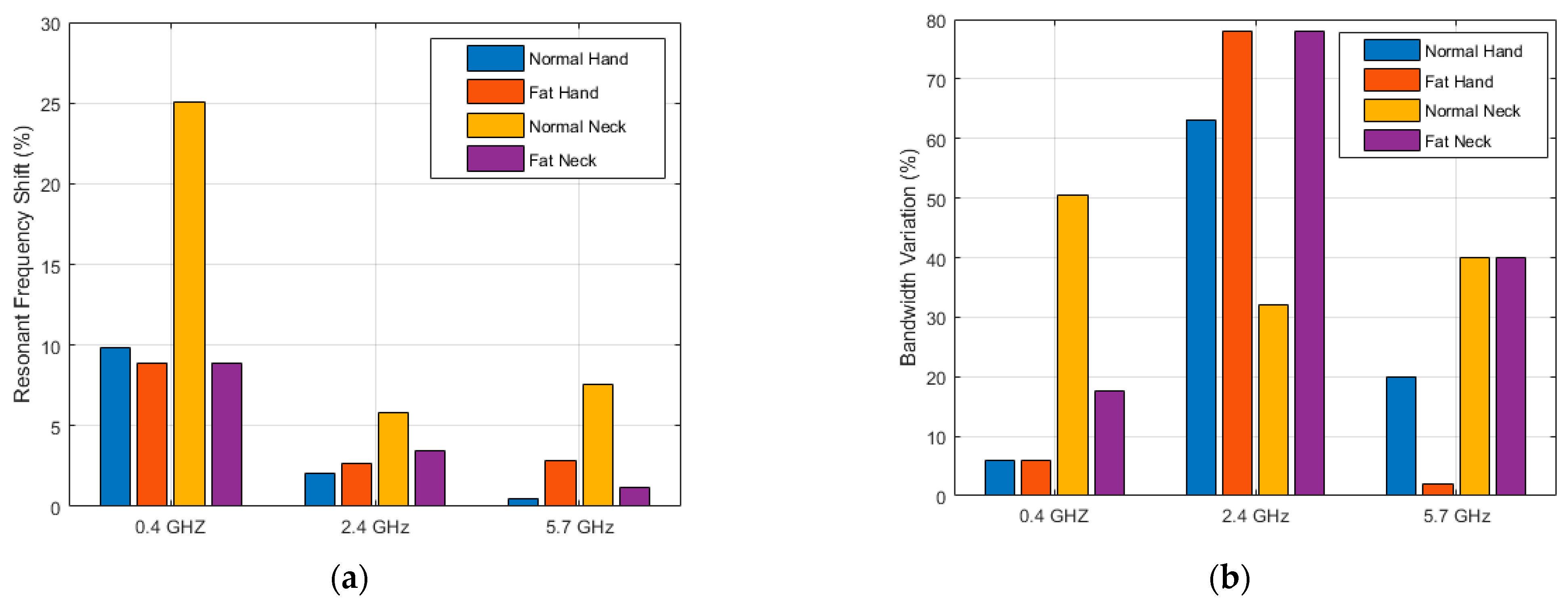
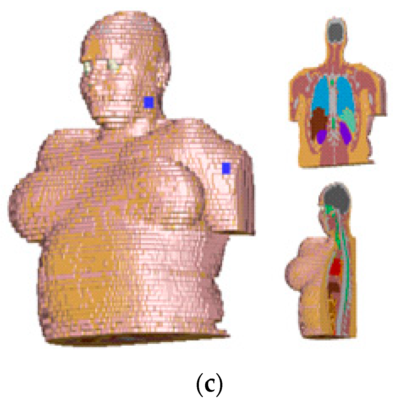
To compare the effect of different human body types on the antennas’ performance, an overweight body model with a greater body fat index was selected, and it is shown in Figure 6. The percentage of the performance variation in both resonant frequency and bandwidth of the meander antenna in the neck and hand of the human voxel are presented. Results show that the resonant frequency and bandwidth are reduced in an overweight voxel in 400 MHZ, but it does not follow an arranged variation pattern at 2.4 GHz and 5.7 GHz bands, although the operational frequency bands are still covered in the overweight voxel similar to the normal voxel.

3.3. Mesaurements

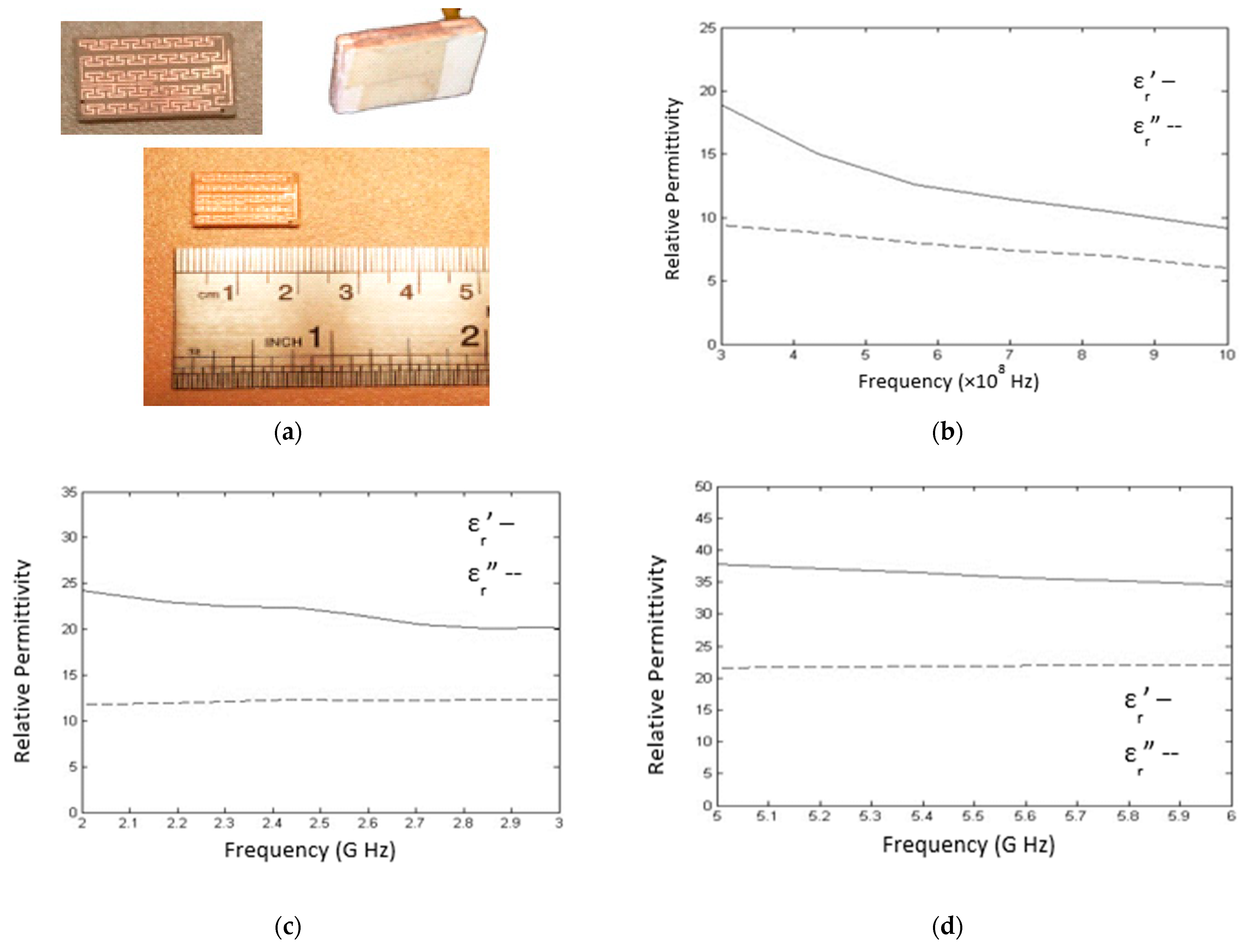
Due to less stringent fabrication requirements for the meandered antenna (Antenna II), it was selected as a sample for fabrication and validation of the simulation results. The fabricated structure of antenna II with and without the superstrate is shown in Figure 7a.
Mixtures of n-butanol, propanol, salt, and purified water with TDS = 5, at different concentrations, were prepared and measured by an open-ended coaxial line [39,40] to make sure the effective EM characteristics of the equivalent three-layer phantom in each frequency band are in good agreement with that of the human tissues (skin, fat, and muscle). The percentage of each material is illustrated in Table 3 in each frequency [41,42]. The results are shown versus the frequency at each band in Figure 7b–d.
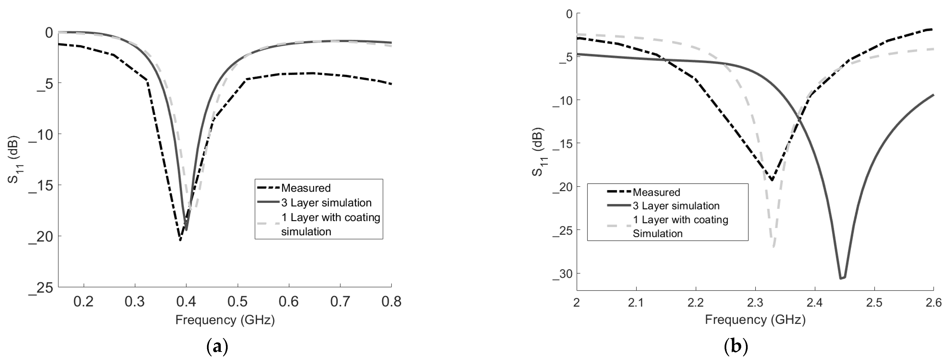
The S11 measurement results are illustrated in Figure 8a–c. The results show a good agreement in the first two bands, between test results and the simulation results of the three-layer mode, but some discrepancies are observed in the third frequency band. The reasons are the nonideal behavior of the connectors, ports, and coaxial cables at 5.7 GHz. The coaxial cable connection to the antenna was done by hand, and this creates impedance mismatches since the input impedance becomes more sensitive to the location of the feeding point as the frequency increases. Furthermore, the need for a thin protective layer on the antenna (with a relative permittivity of approximately 3) to avoid penetration of the liquid to the substrate and replacing a one-layer liquid phantom instead of the three-layer phantom in the measurement are the other reasons for the small differences between simulations and measurement results.
In order to show the effect of the thin protective coating layer and the use of one-layer liquid phantom in the measurement compared to the real three-layer phantom in the simulation, simulation results of the one-layer equivalent phantom with a coating layer are also shown along with the measurement results and the original simulation of the three-layer model with no coating in Figure 8. As expected, the use of a one-layer equivalent phantom with the coating results in a resonance frequency shift to a lower value, and it explains the small discrepancy observed between the measurement results and simulation of the three-layer model with no coating observed in Figure 8b,c. It should also be noted that the effect of the use of a one-layer equivalent phantom with a coating layer is less as frequency decreases, and it is negligible at the 400 MHz band.

4. Discussion and Conclusions

Implantable devices have been playing a critical role in the field of biomedical research and health monitoring. Implantable antennas can support the collection of vital data from a body and reprogramming in-body sets through wireless communications, which can be used in a variety of medical applications, such as heart signal/beat analysis, reprogramming of pacemakers, daily activity recording, skeletal issues and diseases diagnosis, implantable medicine, nerve stimulation, and drug delivery without the need for multiple surgeries.
The resonance frequency of antennas implanted in various people may change and alter the antenna’s impedance matching because the characteristics of human tissues differ from individual to individual. In order to solve this problem, implantable antennas should have a broader bandwidth (BW). Additionally, miniaturization methods are needed to design compact implantable antennas that are compatible for biomedical purposes. Therefore, here, three triple-band implantable antennas with wide bandwidth characteristics and appropriate sizes were designed, analyzed, and compared. These antennas include fractal, meandered, and comb antennas. The antennas operate at three bands: 400 MHz, 2.4 GHz, and 5.7 GHz. The sizes of all antennas are optimized to be implanted, and they are smaller or comparable with similar reported samples. It is also notable that other recent works include only single- or dual-band antennas, and triple-band implantable antennas have rarely been reported in the literature. The BWs of all three presented designs are more than the other reported works. The comb antenna has the best BW among others. Since wider BW is more desirable in case of tissue characteristics variations, the comb antenna is more preferable in our designs. Rogers 3210 was chosen as the substrate and we obtained 120, 320, and 1200 MHz bandwidths at the specified resonant frequencies. The antenna dimensions are 1.4 mm×12 mm × 12 mm. The fractal type antenna is slightly smaller in size among the designs.
To study the performance of the antenna implanted in different body tissues and body types, antennas were placed in different body parts of the human voxels and based on our analysis in all placements operational bands were covered. In human voxel, meander antennas had a better performance stability at 400 MHZ band and comb antenna showed a better performance stability at 2.4 GHz and 5.7 GHz. The meander antenna was selected because of the ease of fabrication for validation and a liquid phantom was provided to measure the S11 of the antenna. The antenna satisfied the SAR limit and the data connectivity requirement. The measurement results were compared to simulations and good agreement was observed.

Author Contributions

Conceptualization, K.S. and S.H.; methodology, K.S., S.H. and H.C.; software simulation, K.S. and S.H.; validation, K.S, S.H. and S.S.; formal analysis, K.S. and S.H.; investigation, K.S., S.S. and H.C.; resources, K.S., S.H. and H.C.; writing—original draft preparation, K.S., S.H. and S.S.; writing—review and editing, K.S. and H.C; supervision, H.C.; project administration, H.C. All authors have read and agreed to the published version of the manuscript.

Funding

H.C. receives support from the National Science Foundation (NSF) CAREER award #1917105.

Institutional Review Board Statement

Not applicable.

Informed Consent Statement

Not applicable.

Data Availability Statement

Not applicable.

Conflicts of Interest

The authors declare no conflict of interest.

References

  1. Kim, J.; Samii, Y.R. Implanted Antennas Inside a Human Body: Simulations, Designs, and Characterizations. IEEE Trans. Microw. Theory Technol. 2004, 52, 1934–1943. [Google Scholar] [CrossRef]
  2. Murphy, O.H.; McLeod, C.N.; Navaratnarajah, M.; Yacoub, M.; Toumazou, C. A Pseudo-Normal-Mode Helical Antenna for Use With Deeply Implanted Wireless Sensors. IEEE Trans. Antenna Propag. 2012, 60, 1135–1139. [Google Scholar] [CrossRef]
  3. Xia, W.; Saito, K.; Takahashi, M.; Ito, K. Performances of an Implanted Cavity Slot Antenna Embedded in the Human Arm. IEEE Trans. Microw. Theory Technol. 2009, 57, 894–899. [Google Scholar] [CrossRef]
  4. Liu, W.C.; Yeh, F.M.; Ghavami, M. Miniaturized Implantable Broadband Antenna for Biotelemetry Communication. Microw. Opt. Technol. Lett. 2008, 50, 2407–2409. [Google Scholar] [CrossRef]
  5. Chow, E.Y.; Chlebowski, A.L.; Chakraborty, S.; Chappell, W.J.; Irazoqui, P.P. Fully Wireless Implantable Cardiovascular Pressure Monitor Integrated with a Medical Stent. IEEE Trans. Biomed. Eng. 2010, 57, 1487–1496. [Google Scholar] [CrossRef]
  6. Tikka, A.C.; Faulkner, M.; Al-Sarawi, S.F. Secure Wireless Actuation of an Implanted Microvalve for Drug Delivery Applications. Smart Mater. Struct. 2011, 20, 105011. [Google Scholar] [CrossRef]
  7. Joo, H.; Lee, Y.; Kim, J.; Yoo, J.S.; Yoo, S.; Kim, S.; Arya, A.K.; Kim, S.; Choi, S.H.; Lu, N.; et al. Soft Implantable Drug Delivery Device Integrated Wirelessly with Wearable Devices to Treat Fatal Seizures. Sci. Adv. 2021, 7, eabd4639. [Google Scholar] [CrossRef]
  8. Mason, P.A.; Murphy, M.R.; Petersen, R.C. IEEE SCC-28 Standards; IEEE EMF Health & Safety Standards. IEEE: Piscataway, NJ, USA, 2019.
  9. Kiourti, A.; Nikita, K.S. Implantable antennas: A tutorial on design, fabrication, and in vivo testing. IEEE Microw. Mag. 2014, 15, 77–91. [Google Scholar]
  10. Bonefačić, D.; Bartolić, J. Small Antennas: Miniaturization Techniques and Applications. Automatika 2012, 53, 20–30. [Google Scholar] [CrossRef] [Green Version]
  11. Wheeler, A. Fundamental Limitations of Small Antennas. Proc. IRE 1947, 35, 1479–1484. [Google Scholar] [CrossRef]
  12. Chu, J. Physical Limitation on Omni-Directional Antennas. J. Appl. Phys. 1948, 19, 1163–1175. [Google Scholar] [CrossRef] [Green Version]
  13. Merli, F.; Bolomey, L.; Meurville, E.; Skrivervik, A.K. Implanted Antenna for Biomedical Applications. In Proceedings of the 2008 IEEE Antennas and Propagation Society International Symposium, San Diego, CA, USA, 5–11 July 2008; pp. 1–4. [Google Scholar]
  14. Kiourti, A.; Nikita, K.S. Miniature Scalp–Implantable Antennas for Telemetry in the MICS and ISM Bands: Design, Safety Considerations and Link Budget Analysis. IEEE Trans. Antennas Propag. 2012, 60, 3568–3575. [Google Scholar] [CrossRef]
  15. Kiourti, A.; Christopoulou, M.; Nikita, K.S. Performance of A Novel Miniature Antenna Implanted in The Human Head for Wireless Biotelemetry. In Proceedings of the 2011 IEEE International Symposium on Antennas and Propagation, Spokane, WA, USA, 3–8 July 2011; pp. 392–395. [Google Scholar]
  16. Huang, F.J.; Lee, C.M.; Chang, C.L.; Chen, L.K.; Yo, T.C.; Luo, C.H. Rectenna Application of Miniaturized Implantable Antenna Design for Triple-Band Biotelemetry Communication. IEEE Trans. Antenna Propag. 2011, 59, 2646–2653. [Google Scholar] [CrossRef]
  17. Li, H.; Guo, Y.-X.; Liu, C.; Xiao, S.; Li, L. A Miniature-Implantable Antenna for MedRadio-Band Biomedical Telemetry. IEEE Antennas Wirel. Propag. Lett. 2015, 14, 1176–1179. [Google Scholar] [CrossRef]
  18. Kumar, P.; Ali, T.; Pai, M.M.M. Electromagnetic Metamaterials: A New Paradigm of Antenna Design. IEEE Access 2021, 9, 18722–18751. [Google Scholar] [CrossRef]
  19. Alibakhshikenari, M.; Virdee, B.S.; Azpilicueta, L.; Naser-Moghadasi, M.; Akinsolu, M.O.; See, C.H.; Liu, B.; Abd-Alhameed, R.A.; Falcone, F.; Huynen, I.; et al. A Comprehensive Survey of Metamaterial Transmission-Line Based Antennas: Design, Challenges, and Applications. IEEE Access 2020, 8, 144778–144808. [Google Scholar] [CrossRef]
  20. Palmeri, R.; Bevacqua, M.T.; Morabito, A.F.; Isernia, T. Design of Artificial-Material-Based Antennas Using Inverse Scattering Techniques. IEEE Trans. Antennas Propag. 2018, 66, 7076–7090. [Google Scholar] [CrossRef]
  21. Althuwayb, A.A. Enhanced Radiation Gain and Efficiency of a Metamaterial-Inspired Wideband Microstrip Antenna Using Substrate Integrated Waveguide Technology for sub-6 GHz Wireless Communication Systems. Microw. Opt. Technol. Lett. 2021, 63, 1892–1898. [Google Scholar] [CrossRef]
  22. Fallahpour, M.; Zoughi, R. Antenna Miniaturization Techniques: A Review of Topology- and Material-Based Methods. IEEE Antennas Propag Mag 2018, 60, 38–50. [Google Scholar] [CrossRef]
  23. Hashemi, S.; Rashed-Mohassel, J. Design and Miniaturization of Dual Band Implantable Antennas. Biocybern. Biomed. Eng. 2018, 38, 868–876. [Google Scholar] [CrossRef]
  24. Nösslinger, H.; Mair, E.; Toplak, H.; Hörmann-Wallner, M. Measuring subcutaneous fat thickness using skinfold calipers vs. high-resolution B-scan ultrasonography in healthy volunteers: A pilot study. Clin. Nutr. Open Sci. 2022, 41, 19–32. [Google Scholar] [CrossRef]
  25. Augustine, R. Electromagnetic Modeling of Human Tissues and Its Application on the Interaction Between Antenna and Human Body in the BAN Context. Ph.D. Thesis, Paris-Est University, Créteil, France, 2009. [Google Scholar]
  26. Volakis, J.L.; Chen, C.C. Small Antennas Miniaturization Techniques and Applications. In McGraw Hill; McGraw Hill: New York, NJ, USA, 2010; Chapter 3. [Google Scholar]
  27. Kraus, J.D.; Marhefka, R.J. Antennas for All Applications, 3rd ed.; McGraw Hill: New York, NJ, USA, 1988. [Google Scholar]
  28. Hansen, R.C. Electrically Small, Superdirective, and Superconducting Antennas; John Wiley & Sons, Inc.: Hoboken, NJ, USA, 2006. [Google Scholar]
  29. Rashed, J.; Tai, C.T. A New Class of Resonant Antennas. IEEE Trans. Antenna Propag. 1991, 39, 1428–1430. [Google Scholar] [CrossRef]
  30. Yongle, W.; Liao, M.; Su, M.; Liu, Y. A Novel Differential Dual-Frequency Patch Antenna with Bandwidth Enhancement. Electromagnetics 2015, 35, 40–48. [Google Scholar]
  31. Xu, L.; Guo, Y.; Wu, W. Miniaturized Dual-Band Antenna for Implantable Wireless Communications. IEEE Antennas Wirel. Propag. Lett. 2014, 13, 1160–1163. [Google Scholar]
  32. Zhu, D.; Guo, Y.X.; Je, M.; Kwong, D.L. Design and in vitro test of differentially fed dual-band implantable antenna operating at MICS and ISM bands. IEEE Trans. Antenna Propag. 2014, 62, 2430–2439. [Google Scholar]
  33. Konstantinos, K. Konstantinos Dual Band Implantable Antenna for Biomedical Telemetry Applications. In Proceedings of the International Conference on Radar, Antenna, Microwave, Electronics, and Telecommunications (ICRAMET), Tangerang, Indonesia, 18–20 November 2020; pp. 253–256. [Google Scholar]
  34. Liu, Y.; Chen, Y.; Lin, H.; Juwono, F.H. A Novel Differentially Fed Compact Dual-Band Implantable Antenna for Biotelemetry Applications. IEEE Antennas Wirel. Propag. Lett. 2016, 15, 1791–1794. [Google Scholar] [CrossRef]
  35. Rana, B.; Shim, J.Y.; Chung, J.Y. An implantable antenna with broadside radiation for a brain–machine interface. IEEE Sens. J. 2019, 19, 9200–9205. [Google Scholar] [CrossRef]
  36. Liu, C.; Zhang, Y.; Liu, X. Circularly Polarized Implantable Antenna for 915 MHz ISM-Band Far-Field Wireless Power Transmission. IEEE Antennas Wirel. Propag. Lett. 2018, 17, 373–376. [Google Scholar] [CrossRef]
  37. Li, R.; Li, B.; Du, G.; Sun, X.; Sun, H. A Compact Broadband Antenna with Dual-Resonance for Implantable Devices. Micromachines 2019, 10, 59. [Google Scholar] [CrossRef] [PubMed] [Green Version]
  38. Jain, L.; Singh, R.; Rawat, S.; Ray, K. Stacked Arrangement of Meandered Patches for Biomedical Applications. Int. J. Syst. Assur. Eng. Manag. 2018, 9, 139–146. [Google Scholar] [CrossRef]
  39. Venkatesh, M.S.; Raghavan, G.S.V. An Overview of Dielectric Properties Measuring Techniques. Can. Biosyst. Eng. 2005, 47, 15–30. [Google Scholar]
  40. Berube, D.; Ghannouchi, F.M.; Savard, P. A Comparative Study of Four Open-Ended Coaxial Probe Models for Permittivity Measurements of Lossy Dielectric/Biological Materials at Microwave Frequencies. Trans. Microw. Theory Techn. 1996, 44, 10. [Google Scholar] [CrossRef]
  41. Lazebnik1, M.; Madsen, E.L.; Frank, G.R.; Hagness, S.C. Tissue-mimicking Phantom Materials for Narrowband and Ultra Wideband Microwave Applications. Phys. Med. Biol. 2005, 50, 4245–4258. [Google Scholar] [CrossRef] [PubMed]
  42. Porter, E.; Fakhoury, J.; Oprisor, R.; Coates, M.; Popović, M. Improved Tissue Phantoms for Experimental Validation of Microwave Breast Cancer Detection. In Proceedings of the European Conference on Antennas and Propagation, Barcelona, Spain, 12–16 April 2010. [Google Scholar]
Figure 1. Geometry of Antenna I based on Hilbert design (a) top view, (b) side view; Antenna II based on the meandered structure (c) top view, (d) side view; Antenna III based on so called comb structure (e) top view, (f) side view; and (g) Side view of implanted antenna inside multi-layer tissue model.
Technologies 10 00091 g001aTechnologies 10 00091 g001b
Figure 3. Flowchart procedure for design of a multiple-band implantable antenna.
Technologies 10 00091 g003
Figure 4. (ac) Comparison of S11 of the three antennas around 400 MHz, 2.4 GHz, and 5.6 GHz. (Antenna I __ _, Antenna II ______, Antenna III _ _ _ _). (df) Patterns of the Antenna I in three bands. (gi) Patterns of the Antenna II in three bands, and (jl) Patterns of the Antenna III in three bands.
Technologies 10 00091 g004aTechnologies 10 00091 g004bTechnologies 10 00091 g004c
Figure 5. Performance comparison of the meandered and comb antennas for different placements of the antennas in the human voxel model and in the three-layer phantom model. (a) Meandered antenna’s resonant frequency alteration percentage at each frequency band (b) Meandered antenna’s bandwidth alteration percentage at each frequency band (c) Comb antenna’s resonant frequency alteration percentage at each frequency band (d) Comb antenna’s resonant frequency alteration percentage at each frequency band, and (e) Positions of antenna’s placement in the human voxel.
Technologies 10 00091 g005aTechnologies 10 00091 g005b
Figure 6. Impact of different bodies on antenna characteristics is shown. A fat body voxel is compared to a normal body type in Figure 4. (a) percentage of the resonant frequency variation in normal and overweight voxels are compared, (b) percentage of the bandwidth variation in the normal and overweight voxels are illustrated, and (c) overweight human voxel and the positions of the antenna’s placement are shown.
Technologies 10 00091 g006aTechnologies 10 00091 g006b
Figure 7. (a) Fabricated structure of the antenna with and without superstrate. (bd) Measurement of the relative permittivity of equivalent phantoms at the three bands.
Technologies 10 00091 g007
Figure 8. (ac) Measurement of the S11 of the fabricated meandered antenna in the equivalent phantom along with the simulation results of the three-layer model with no coating layer and the one-layer equivalent phantom with the coating layer at the three bands.
Technologies 10 00091 g008aTechnologies 10 00091 g008b
Table 2. SAR in one gram of tissue by 1 W stimulation.
400 MHz Band
SAR 1 g (W/Kg)
2.4 GHz Band
SAR 1 g (W/Kg)
5.7 GHz Band
SAR 1 g (W/Kg)
Antenna I494344320
Antenna II308292328
Antenna III94296572
Table 3. Materials of the liquid phantoms.
Volume PercentageN-Butanol 96%Propanol 99%Purified Water TDS = 5SaltFrequency Band
Phantom 149491.90.1400 MHz
Phantom 2313137.70.32.4 GHz
Phantom 312.512.574.350.155.6 GHz
Publisher’s Note: MDPI stays neutral with regard to jurisdictional claims in published maps and institutional affiliations.