Abstract
In recent decades, many researchers have focused on the design and development of exoskeletons. Several strategies have been proposed to develop increasingly more efficient and biomimetic mechanisms. However, existing exoskeletons tend to be expensive and only available for a few people. This paper introduces a new gravity-balanced upper-limb exoskeleton suited for rehabilitation applications and designed with the main objective of reducing the cost of the components and materials. Regarding mechanics, the proposed design significantly reduces the motor torque requirements, because a high cost is usually associated with high-torque actuation. Regarding the electronics, we aim to exploit the microprocessor peripherals to obtain parallel and real-time execution of communication and control tasks without relying on expensive RTOSs. Regarding sensing, we avoid the use of expensive force sensors. Advanced control and rehabilitation features are implemented, and an intuitive user interface is developed. To experimentally validate the functionality of the proposed exoskeleton, a rehabilitation exercise in the form of a pick-and-place task is considered. Experimentally, peak torques are reduced by 89% for the shoulder and by 84% for the elbow.
1. Introduction
Exoskeletons are mechanical structures that are mostly employed in industrial and rehabilitation fields. In the first case, mechanical structures are used to help the operator to execute heavy tasks. In the second case, rehabilitation requires structures that help the patient to restore or recover lost motion abilities. Depending on the application, exoskeletons can be designed for power amplification [1], neuromuscular impairment compensation [2,3] and rehabilitation [4,5] and to support disabled people in activities of daily living (ADL) [6].
In the context of rehabilitation, to fully or partially recover physiological motion capabilities, patients receive rehabilitation treatment based on active and repetitive exercises [7,8,9,10]. In this context, upper-limb exoskeletons have attracted great attention over the years, and several surveys on upper-limb rehabilitation robotic devices can be found [11,12,13,14,15]. In fact, exoskeletons can be employed to assist the medical operator, increasing rehabilitation performance [16,17,18,19] and diminishing healthcare expenses. Therapy sessions can be performed in parallel supervised by a single therapist, patients can benefit from a prolonged therapy time (increasing therapy effectiveness), and a greater repeatability can be reached during the motion task execution. Even though several classifications are proposed in the literature [20] (e.g., field of application, active or passive, degrees of freedom (DOFs) of the system, type of actuation and portable or fixed), two main categories of devices can be found when comparing the mechanical structure: end-effector-based systems and exoskeleton-based systems [21]. End-effector-based systems are in contact with the human limb at its most distal part only (e.g., the hand). For this reason, they have a simpler mechanical structure. However, it is not possible to impose specific movements to a particular human joint. Typical end-effector-based systems include serial manipulators (e.g., MIT Manus [22] and ACRE [23]) and parallel (e.g., CRAMER [24] and InMotion ARM [25]) and cable-driven robots (e.g., NeReBot [26] and MACARM [27]). Unlike end-effector manipulators, exoskeletons have serial link chains, allowing one to exactly reproduce the physiological movement of each joint of the limb. Moreover, they can fully or partially compensate upper-limb weight. To reach these aims, they require adaptation of the length segments to the patient limb, which may take a significant amount of time. Furthermore, to avoid damage to the patient, proper designs are required to match the position of the center of the rotation of the human limb with that of the mechanical structure [28]. Even if a high-performance and a comfortable exoskeleton can be found [29], very little consideration has been given to the minimization of system costs. To the best of our efforts, we were not able to find specific literature on upper-limb complete systems (i.e., comprising the mechanical structure, the software and the electronics) developed with the intention of being low cost for rehabilitation purposes: a few low-cost exoskeleton mechanical structures were found but in an embryonic state [30,31]. As a result, the vast majority of existing devices are cost prohibitive for most people, preventing any personal or domestic use. Starting from these considerations, this paper introduces a low-cost exoskeleton concept developed for the rehabilitation of the upper limb. The main objective of the presented concept is to show a significant cost reduction with respect to existing designs. This contribution describes our mechanical, electronic and sensing designs. Although the main focus of this work is on the mechanics, we need to consider that the choices of electronic architectures and sensing can also lead to a significant cost reduction. From the point of view of electronics, high costs are usually associated with real-time Oss (RTOSs), which are cost demanding in terms of the required computational resources and/or in terms of licenses. From the point of view of sensing, we need to acknowledge that commercial force sensors are usually very expensive components.
As the first step in the direction of designing affordable exoskeletons, we consider a simplified target application: rehabilitation exercises characterized by only two DOFs in the sagittal plane (namely, shoulder and elbow flexion/extension). After a brief literature review on the available exoskeletons (Section 1), the present paper focuses on the proposed exoskeleton design—including the mechanics and electronics—and briefly describes advanced rehabilitation features (Section 2). Then, preliminary tests conducted on one healthy subject are reported (Section 3), and conclusions are drawn (Section 5).
State of the Art
In this section, the latest developments in upper-limb exoskeleton technology for rehabilitation are discussed. Some of them have been commercialized, while others are research prototypes. The Harmony [5] exoskeleton consists of an active five-DOF shoulder mechanism, one DOF elbow mechanism and one DOF wrist mechanism powered by series elastic actuators (SEAs). It exhibits good kinematic compatibility with the human body with a wide range of motion, and it performs task-space force and impedance control. The Alex 2 exoskeleton [32] was developed based on a similar concept, but, unlike the Harmony exoskeleton, it uses series elastic tendon transmission, which guarantees intrinsic mechanical compliance. Hsieh et al. [33] has proposed a mechanism specifically designed for shoulder rehabilitation. It consists of two spherical mechanisms, two slider crank mechanisms and a gravity-balancing mechanism. The side-by-side disposition of the actuators ensures not only lower inertia properties but also compactness and less weight. A mechanism with a passive joint is introduced to compensate the misalignment of the exoskeleton with the human limb in the case of variable physiological parameters of the user. Linear SEAs have been used. Hunt et al. [34] proposed a spherical joint based on a 3-UPU (U and P are universal and prismatic joints, respectively) Gough–Stewart platform. The three prismatic joints are actuated. Two additional passive joints (corresponding to a translation and a rotation) connect the platform to the human limb. NEUROExos [35] is an elbow-powered exoskeleton designed for post-stroke rehabilitation of the arm, ensuring comfort for the patient. Misalignment problems have been addressed by mounting the active rotational joint on a moveable translational passive mechanism, which decouples the robot joint rotations from axis translations. Undesired forces resulting from a rigid connection between the limb and the system are avoided, while assistive forces can be performed. Oguntosin et al. [36] proposed the EasoftM, a 3D printed exoskeleton with passive joints to compensate for gravity and with active joints to rotate the shoulder and elbow joints. It resulted in a lightweight system that assists planar reaching motion. Wu et al. [37] proposed a gravity-balanced exoskeleton with a flexible Bowden cable transmission system for active rehabilitation training of the upper limb. Gravity balancing of the human arm and mechanism is achieved using auxiliary links and zero free length. Those described here are only a small selection of all the exoskeletons commercially available or presented in the literature: high-performance and comfortable exoskeletons can be found [29]. A more detailed description of the state of the art can be found in [38,39,40,41]. As mentioned before, to date, very little consideration has been given to affordability arguments, and the vast majority of existing devices are cost prohibitive. High costs are associated with compact high-torque actuation [42,43]. (which often includes expensive harmonic drive reduction stages), cable-driven systems [32] (which require high-precision manufacturing), commercial force sensors [44] and high-performance RTOS solutions (which usually require high computational resources to execute hard real-time processes at suitable control frequencies) [45], [46]. For reference, the average cost for a complete upper-limb exoskeleton with five–six actuated joints is in the order of USD 130,000 [47]. This price hinders the availability of exoskeletons in small therapeutic centers or in domestic settings, which, otherwise, could lead to longer lasting and more effective therapies.
2. Materials and Methods
The proposed exoskeleton concept (Figure 1) is meant to be attached to a fixed element (i.e., a wheelchair), and it can be used for rehabilitation or as a daily life assistive device. In this paragraph, the mechanical design and manufacturing are presented, and the balancing spring system adopted to reduce the motor requirements is described. In addition, the therapy features implemented in order to use this device in the context of robotic rehabilitation are presented in Section 2.4.
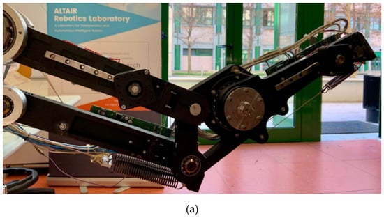
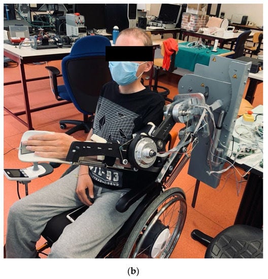
Figure 1.
The novel prototype, (a) overview and (b) mounted on a patient’s wheelchair.
2.1. Mechanical Design and Manufacturing
The upper-limb exoskeleton constructive design is shown in Figure 2. The mechanism was designed to interface with the left arm and forearm of the patient. Considering that the device is thought to help the subject in rehabilitation or in pick-and-place tasks of lifting and lowering different objects, whose trajectories mostly take place within the sagittal plane [48], the exoskeleton was designed to provide two DOFs on such a plane, namely, shoulder and elbow flexion/extension.
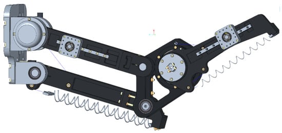
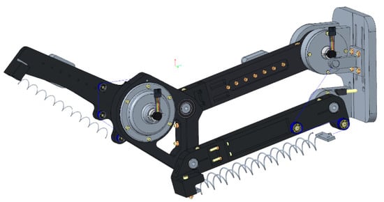
Figure 2.
Exoskeleton constructive design.
The structure is composed of five links (namely, 1, 2, 3, 4 and 5), with each one connected to the adjacent one by means of a revolute joint. The constraints imposed by the revolute joints force the system to move on a plane. A parallelogram linkage O1O2AB (constituted by the links 1, 2, 3 and 4) is used as the upper arm link (Figure 3), while link 5 is used in an open chain as the forearm link. A spring–pulley–cable-based compensation system is employed to minimize motor requirements. Figure 2 illustrates the system based on a zero-free-length spring: a cable, rigidly fixed to the frame (or to link 4), and the extension springs, rigidly fixed on link 3 (or on link 5), are connected by a cable wrapping on idle pulleys. The gravity-balancing system (GBS) was designed considering the weight forces of the links and human limbs.
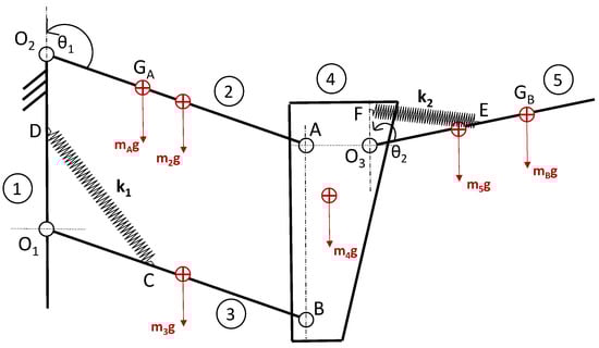
Figure 3.
Parallelogram-based design.
With reference to Figure 3, mA and mB are the masses of the forearm and upper arm, respectively, and mi and li (i = 1,…,4, l4 is equal to AO3) are the mass and length of the i-th link, respectively. The center of the mass of each link is positioned in the centroid of the link (for links 2, 3 and 5, the center of mass is in the middle of the link). The center of mass of the limbs is positioned at points GA and GB. rA is the distance between GA and O2, and rB is the distance between GB and O3. Two springs, CD and EF, with stiffness k1 and k2, respectively, are adopted. Points C, D, E and F are the connection points of the springs to the system. The two DOFs θ1 and θ2 are controlled by two equal electric motors (Maxon Motor DCX22L with GPX22UP 103:1 reducer) connected to links 2 and 5 with the axis normal to the motion plane and passing through points O2 and O3, respectively.
The mechanical ranges of motion (ROMs) are 165° at the shoulder and 150° at the elbow joint. The final exoskeleton was found to be lightweight (Table 1).

Table 1.
Parameters of the mechanical system.
The human–robot interface (HRI) connects the subject’s left upper arm and forearm to the exoskeleton by a passive two-DOF mechanism: each body region is rigidly connected to a support brace. Each brace is paired with the carry of a linear guide (carry: RM9NUU—RBX and railway: RM9R 0140 10/10—RBX) through a revolute joint. The railway of the linear guide is then rigidly connected to the exoskeleton link.
The fuse deposition modeling machine MarkTwo by MarkForged was chosen to produce the patient-specific component of the mechanism, improving the system’s weight. MarkTwo realizes carbon fiber-reinforced thermoplastic (CFRT) parts [49,50,51,52,53,54,55] by depositing continuous fibers on a polymeric matrix made of the proprietary material “onyx” (whose mechanical characteristics are listed in Table 2), which consists of nylon filled with chopped carbon fibers.
Table 2.
Onyx and carbon fiber-reinforced onyx mechanical characteristics.
Components requiring mechanical isotropic behavior (such as pins or motor housings) were manufactured by 7075 Aluminum CNC machining.
2.2. Gravity Balance Compensation
A balancing compensation system was adopted to relieve the motor from the torque component due to the weight of the links of the human limbs (whose values are reported in Table 3) and of a 0.5 kg payload positioned in the tip of link 5.
Table 3.
Human parameters of a 30-year-old male, who is an uncompromised, normal, healthy volunteer. M and r express the human limb total mass and the distance between its center of gravity and the flexion/extension axis, with A and B representing the forearm and the upper arm, respectively.
In general, balancing a mass at the end of a two-link open-loop chain is not an easy task [56]. In this case, the position of the forearm link is defined by the angles θ1 and θ2, so a two-link open-loop chain renders it impossible to relate the direction of the force exerted by the forearm spring to parameter θ2 only (defined as the angle between the vertical and the forearm directions), making the forearm system dependent on both θ1 and θ2. To decouple the two motions, parallelogram linkage was adopted so that link 4 does not change the orientation and to ensure that the forearm link depends only on θ2.
A parametric optimization was conducted to define the position of points C, D, E and F, which minimize the motor requirements. Points C and F are along the direction defined by links 2 and 5, respectively (c and f are the distances of points C and F with respect to points O1 and O3, respectively), whereas points D and E are along the vertical direction passing through points O1 and O3, respectively (d and e are the distances of points D and E with respect to points O1 and O3, respectively).
According to the zero-free-length spring theory [56], the optimal value of the spring stiffness is
where r2, r3 and r5 correspond to half of the length of the links 2, 3 and 5, respectively.
The torques τ1 (shoulder) and τ2 (elbow) generated by the motors in order to statically balance the system can be written as a function of the parameters c and d, and e and f, respectively.
A parametric optimization was conducted with MATLAB, and the optimal values obtained are shown in Table 4. The springs’ stiffness values k1 and k2 are 1.9 N/mm and 0.5 N/mm, respectively.
Table 4.
Spring position optimal values.
A dynamic rigid multi-body simulation was conducted with PTC Creo Parametric Mechanism in order to determine the reduction in the motor peak torque. For the angles θ1 and θ2, the trajectories shown in Figure 4 were considered (a worst-case scenario pick-and-place task was considered), and the motor torques τ1 and τ2 were compared with the motor torques of the same mechanical structure considered without the GBS. No friction was taken into account in the model. Figure 5 shows the motor torque considering the shoulder and the elbow joints for the balanced structure (light green) and the unbalanced structure (dark green).
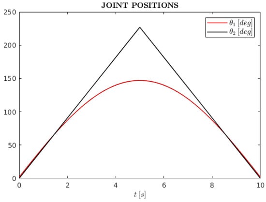
Figure 4.
Trajectories of θ1 (shoulder joint angle) and θ2 (elbow joint angle) during a pick-and-place task simulation.
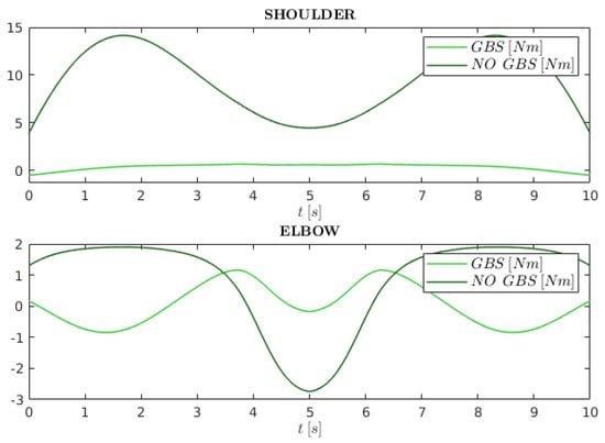
Figure 5.
Simulated required drive torques at the shoulder and the elbow joints (namely, τ1 and τ2) during a pick-and-place task. In light green, the gravity-balancing system (GBS), and in dark green, a non-balanced system (NO GBS).
The benefit of employing the GBS is significant: motor torque requirements are reduced by 95% for the shoulder and by about 60% for the elbow (peak and RMS motor torque values are shown in Table 5).
Table 5.
Peak motor torque values for the balanced mechanical structure (BMS) and unbalanced mechanical structure (UMS).
Indeed, in the case of a mechanically unbalanced design, the torque and power required at the actuator joint could be provided by the following solution (while maintaining reasonable compact sizes):
- Shoulder joint: Maxon Motor EC-90 flat (323772) with a 1:50 reducer, e.g., NLHSG-I 17–50;
- Elbow joint: Maxon Motor EC-45 flat (397172) with a 1:50 reducer, e.g., NLHSG-I 14–50.
Due to the balancing system, a smaller size and, thus, (in general) cheaper motors can be used.
2.3. Electronics and Sensing
This section describes our efforts to reduce the cost of the hardware infrastructure for communication, sensing and control. The whole infrastructure is composed of a Raspberry PI, which communicates with two Actuation Boards (Figure 6c) via SPI over the RS-485 protocol; one Interface Board (Figure 6a), which provides SPI connections between the Raspberry and the Actuation Boards; and one Power Board (Figure 6b), which provides the power supply to all the boards. Further details on the architecture are reported hereafter. The objectives of this infrastructure are (1) to guarantee fast and hard real-time execution of control processes, communication processes and oversampling processes; (2) to guarantee soft real-time communication between the low-level control algorithms and high-level centralized supervision algorithms; (3) to perform signal acquisition, logging and sharing between boards; and (4) to ensure safety of the device in the case of an error or malfunctioning of one module. Instead of using expensive commercial solutions, these characteristics were obtained using low-cost components and custom-designed boards thanks to firmware and software modules, which maximize the use of microprocessor peripherals to guarantee real-time execution and communication. One of the main issues we had to solve is the hard real-time periodic execution of the following three processes on the Actuation Board microprocessor: (1) the control process, which should run at least at 1–5 kHz, required for closing a quality force control loop; (2) the communication process, which is responsible for receiving control commands and sending back sensor data and should run at least at 500 Hz, as it may involve some position feedback; and (3) the oversampling process, which should run as fast as possible, up to the ADC sampling frequency, in order to filter out the noise coming from the low-cost sensors and electronics. To reach this kind of performance without relying on expensive commercial solutions, we made extensive use of microprocessor DMA. In particular, we could guarantee hard real-time execution by making the control process as the unique running process and by implementing communication and acquisition tasks as DMA procedures, exploiting hardware parallel execution. In particular, our design allows us to guarantee the following hard real-time execution frequencies: 3 kHz for the actuator control process, 0.5 kHz for the communication process (by using DMA in combination with the SPI interface) and 1.500 kHz for oversampling (by using DMA in combination with ADCs). Such a high oversampling frequency allows us to significantly reduce the sensor noise, where each sample of the clean signal is obtained by averaging 128 samples. Such fast oversampling becomes of paramount importance in the case of noisy low-cost sensors. Indeed, to further reduce the system cost, we substituted high-end commercial force sensors with low-cost strain gauges directly attached to 3D printed links. The link’s bending stiffness is sized by acting on its form factor and on the quantity and arrangement of the carbon fibers in order to optimally exploit the strain gauge sensitivity. Small link deflections produce variations in the strain gauge resistance, which is then converted into a voltage using inexpensive electronics: a Wheatstone bridge in series to an instrumentation amplifier. The advantage of fast oversampling is shown in Figure 7 (on the left side) together with a picture representing the arrangement of the strain gauges (on the right side).
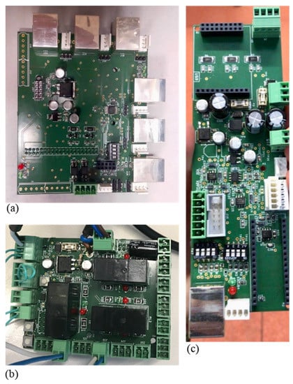
Figure 6.
The custom low-cost electronic design: (a) the Interface Board, (b) the Power Board and (c) the Actuation Board.
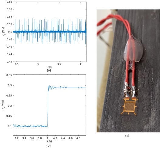
Figure 7.
Figure representing (a) a raw strain gauge signal, (b) strain gauge signal read and filtered exploiting DMA and (c) strain gauge attached to the exoskeleton 3D printed link.
A detailed overview of the whole hw/sw infrastructure is described in below. High-level supervision algorithms are implemented through dedicated ROS nodes that run on a commercial Raspberry Pi4. The Interface Board (Figure 6a) provides input, output and SPI interconnections with the Actuation Boards. Although only two joints are currently used, the system supports up to six Actuation Boards. To ensure communication over longer distances, the Interface Board implements SPI over the RS-485 protocol. Indeed, the SPI standard is TTL—3.3 V, while the RS-485 protocol uses a differential channel −7.5 V to +12 V, allowing longer distances to be covered at the same baud rate. The Interface Board is connected to the Power Board (Figure 6b), which provides supply to all the other boards. It also implements a safety system allowing the motor power to be cut in the case of an emergency or error. Each motor is driven by an Actuation Board (Figure 6c), which includes a low-cost microcontroller that executes the low-level control algorithms, a power driver (ESCON 50/5) and interfaces to the electronics and sensors. The Actuation Board can read one incremental encoder with the RS-422 interface, one 0–3.3 V signal, one −10 V/+10 V signal and one USART or I2C sensor. The Actuation Board also allows SPI communication over the RS-485 protocol.
2.4. Rehabilitation Features
In order to use the device in the context of robotic rehabilitation, advanced control and rehabilitation features were implemented, and an intuitive user interface was developed. While force and impedance control aspects are discussed in [57], this section briefly describes the rehabilitation features accessible through our graphical interface.
The interface is designed to ease system calibration and to manage rehabilitation exercises, following the flowchart in Figure 8. A video of the system, including the graphical interface, is attached, which is also available in [54].
Figure 8.
Flowchart representing the UI life cycle.
The software provides a real-time visualization of the human joints’ configuration, and different rehabilitation exercises are designed to help the wearer following a trajectory in Cartesian space. Dynamic movement primitive (DMP) technology was used to record, play back and customize trajectories in the task space [58]. Using DMPs, trajectories can be pre-recorded and easily reconfigured by changing the target point and the velocity. Moreover, DMPs allow patient-adaptive behaviors, where the task is automatically “scaled” to the patient’s skills. For example, the velocity can automatically decrease if the user is “in late” with respect to the expected trajectory evolution.
Each exercise consists of the user reaching a non-arbitrary point in the exoskeleton workspace while being assisted by the actuators and visual feedback (as represented in Figure 9). As such, great focus has been put on the gamification of rehabilitation tasks, e.g., by giving the patient a score based on their performance and by generating a different trajectory after each attempt. The software stack was built around Godot, a game engine and ROS.
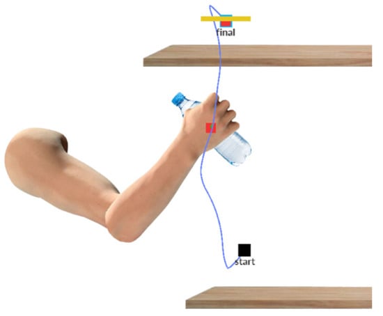
Figure 9.
A snapshot of the UI showing the user executing a pick-and-place task.
3. Experimental Results
To experimentally validate the functionality of the proposed exoskeleton, a rehabilitation exercise in the form of a pick-and-place task, assisted using impedance control technology, was considered. The main objective of such an experiment is to validate the reduction in peak torques claimed in Section 2.2. Using DMPs, we implemented a rehabilitation exercise similar to the one simulated in Section 2.2 and with assistive torques reaching similar peak values. We acknowledge that human variability may strongly affect trajectories, but, here, we were only interested in reaching the proper peak torques. Therefore, we selected a single trial where peak torques reach about 12 Nm for the shoulder and 2 Nm for the elbow.
A 30-year-old healthy subject was involved, whose parameters are shown in Table 3. As shown in Figure 10, the wearer, starting from pose A, is supposed to pick a bottle located at point B and place it on point C. The light gray trajectory was recorded by exploiting DMP technology, and the red line represents the exercise executed by the wearer with the support of the device. Displacements between the red and gray lines occur because the device follows the “assist as needed” paradigm without forcing the user to rigidly follow the trajectory. Indeed, impedance control technology is used to develop a force field with the aim of correct exercise execution. The force field intensity represents the level of assistance and can be set via the graphical interface.
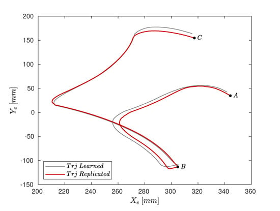
Figure 10.
Representation of the exoskeleton end-effector position in the Cartesian space during a pick-and-place task operation.
In order to validate the reduction in motor torque requirements using the GBS, the measured experimental torques that were needed to execute the pick-and-place task trajectory (Figure 10) were compared with the simulated ones.
Figure 11 represents the simulated and the experimental motor torques with and without the GBS (the motor torques without the GBS are only available in the simulation, which considered the same trajectory of the experiment). The light green and the dark green lines refer to the simulations of the proposed exoskeleton prototype during the task. Simulations were carried out considering the exoskeleton parameters shown in Table 1 and identified the human parameters summarized in Table 3. The simulated data were compared with the experimental data (highlighted with red dashed lines) measured during the experimental campaign.
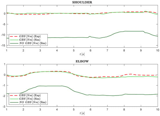
Figure 11.
Simulated (light and dark green lines) and measured (red dashed lines) torques at the elbow and shoulder joints during the pick-and-place task shown in Figure 9.
Finally, peak torques considering the experimental scenario are highlighted in Table 6.
Table 6.
Peak motor torque values for the balanced mechanical structure (BMS) and unbalanced mechanical structure (UMS) considering the experimental curves shown in Figure 10.
4. Discussion
The experimental results show that by taking advantage of the proposed GBS and parallelogram-based design, motor requirements are significantly reduced. Theoretically, the peak motor torque was reduced by 95% for the shoulder actuator and by about 60% for the elbow one (see Table 5). This was confirmed experimentally, showing an 89% peak torque reduction for the shoulder gearmotor and an 84% reduction for the elbow one (see Table 6). These findings validate the statements in Section 2.2. The discrepancy between the experimental (light green line) and the simulated tasks (dashed red line) shown in Figure 11. Figure 11 is due to the difficulty of assessing specific parameters within the analytical simulation, such as:
- The actual inertial parameters of human limbs;
- Bearings and motor friction;
- The inherent hysteresis of the spring behavior;
- Cable elasticity.
The achieved torque reduction allowed us to use small-sized motors both at the shoulder and elbow joints characterized by lower costs in comparison to existing exoskeleton designs.
In total, the exoskeleton prototype costed about EUR 3000: the achieved saving with respect to a reasonable non-balanced mechanism (i.e., with gearmotors capable of actuating an exoskeleton without the GBS) was found to be approximately 65%. In addition, it is to be considered that, in the case of a fairly large-scale production, the cost of aluminum alloy and commercial components can be reduced by more than 50%, cutting down the expenses even more. Additionally, the proposed custom electronic and force-sensing design has an extremely low impact on the overall cost, except for the motor drivers, for which we relied on a commercially available solution.
5. Conclusions
Physical disability often needs long-lasting rehabilitation, which is, for the most part, at the expense of the patient. To reduce the cost of rehabilitation, an affordable upper-limb exoskeleton concept was proposed. As significant costs are usually associated with high-torque actuation, we proposed a design consisting of a parallelogram structure with a gravity-balancing system, which allowed us to employ motors with a smaller size with respect to a traditional serial chain design. Similarly, we proposed electronic and sensing designs to achieve significant cost minimization. The experiments demonstrated that the peak torques were reduced by 89% for the shoulder and by 84% for the elbow with respect to the same unbalanced mechanism. The achieved torque reduction allowed us to use inexpensive motors both at the shoulder and elbow joints. Additionally, they have an extremely small size and low weight in comparison to existing exoskeleton designs. With an overall cost of EUR 3000, the proposed prototype experimentally demonstrated (1) the ability to generate sufficient forces/torques for the considered application and (2) to support advanced control and rehabilitation features. Future research directions should include the extension to four–five DOFs to allow functional exercises and clinical trials with patients.
Author Contributions
Conceptualization, E.P., R.V. (Rocco Vertechy) and A.C.; methodology, E.P. and L.L.; software, E.P., M.M., R.V. (Rudy Vicario), R.F.L. and E.D.; validation, E.D. and E.P.; formal analysis, E.P. and L.L.; investigation, A.C. and E.P.; resources, A.C. and R.V. (Rocco Vertechy); data curation, E.D., R.F.L., R.V. (Rudy Vicario) and M.M.; writing—original draft preparation, E.P. and L.L.; writing—review and editing, E.P. and A.C.; visualization, E.P.; supervision, R.V. (Rocco Vertechy), A.C. and L.L.; project ad-ministration, A.C.; funding acquisition, A.C. All authors have read and agreed to the published version of the manuscript.
Funding
This project has received funding under the European Union’s Horizon 2020 programme under grant agreement EUROBENCH n. 779963 and has been supported by the project “Progettazione di un’ortesi robotica per l’arto superiore con controllo mioelettrico e indirizzata a soggetti con debolezza muscolare” (project code 165-3-11-2018) funded by Regione Veneto.
Institutional Review Board Statement
Not applicable.
Informed Consent Statement
Informed consent was obtained from all subjects involved in the study.
Data Availability Statement
Not applicable.
Conflicts of Interest
The authors declare no conflict of interest.
References
- Kim, S.; Nussbaum, M.A.; Esfahani, M.I.M.; Alemi, M.M.; Jia, B.; Rashedi, E. Assessing the influence of a passive, upper extremity exoskeletal vest for tasks requiring arm elevation: Part II–“Unexpected” effects on shoulder motion, balance, and spine loading. Appl. Ergon. 2018, 70, 323–330. [Google Scholar] [CrossRef] [PubMed]
- Carmeli, E.; Peleg, S.; Bartur, G.; Elbo, E.; Vatine, J.-J. HandTutorTM enhanced hand rehabilitation after stroke—A pilot study. Physiother. Res. Int. 2011, 16, 191–200. [Google Scholar] [CrossRef] [PubMed]
- Nilsson, M.; Ingvast, J.; Wikander, J.; von Holst, H. The Soft Extra Muscle system for improving the grasping capability in neurological rehabilitation. In Proceedings of the 2012 IEEE-EMBS Conference on Biomedical Engineering and Sciences, Langkawi, Malaysia, 17–19 December 2012. [Google Scholar] [CrossRef]
- Bianchi, M.; Fanelli, F.; Conti, R.; Governi, L.; Meli, E.; Ridolfi, A.; Rindi, A.; Vannetti, F.; Allotta, B. Design and Motion Analysis of a Wearable and Portable Hand Exoskeleton. Biosyst. Biorobotics 2016, 16, 373–377. [Google Scholar] [CrossRef]
- Kim, B.; Deshpande, A.D. An upper-body rehabilitation exoskeleton Harmony with an anatomical shoulder mechanism: Design, modeling, control, and performance evaluation. Int. J. Robot. Res. 2017, 36, 414–435. [Google Scholar] [CrossRef]
- Christensen, S.; Bai, S. Kinematic Analysis and Design of a Novel Shoulder Exoskeleton Using a Double Parallelogram Linkage. J. Mech. Robot. 2018, 10, 041008. [Google Scholar] [CrossRef]
- Bütefisch, C.; Hummelsheim, H.; Denzler, P.; Mauritz, K.-H. Repetitive training of isolated movements improves the outcome of motor rehabilitation of the centrally paretic hand. J. Neurol. Sci. 1995, 130, 59–68. [Google Scholar] [CrossRef]
- Feys, H.M.; De Weerdt, W.J.; Selz, B.E.; Steck, G.A.C.; Spichiger, R.; Vereeck, L.; Putman, K.; Van Hoydonck, G.A. Effect of a Therapeutic Intervention for the Hemiplegic Upper Limb in the Acute Phase After Stroke. Stroke 1998, 29, 785–792. [Google Scholar] [CrossRef]
- Van Der Lee, J.H.; Wagenaar, R.C.; Lankhorst, G.J.; Vogelaar, T.W.; Devillé, W.L.; Bouter, L. Forced use of the upper extremity in chronic stroke patients: Results from a single-blind randomized clinical trial. Stroke 1999, 30, 2369–2375. [Google Scholar] [CrossRef]
- Barreca, S.; Wolf, S.L.; Fasoli, S.; Bohannon, R. Treatment Interventions for the Paretic Upper Limb of Stroke Survivors: A Critical Review. Neurorehabilit. Neural Repair 2003, 17, 220–226. [Google Scholar] [CrossRef]
- Frisoli, A.; Salsedo, F.; Bergamasco, M.; Rossi, B.; Carboncini, M.C. A force-feedback exoskeleton for upper-limb rehabilitation in virtual reality. Appl. Bionics Biomech. 2009, 6, 115–126. [Google Scholar] [CrossRef] [Green Version]
- Tsagarakis, N.; Caldwell, D.G. Development and Control of a ‘Soft-Actuated’ Exoskeleton for Use in Physiotherapy and Training. Auton. Robot. 2003, 15, 21–33. [Google Scholar] [CrossRef]
- Nef, T.; Riener, R. ARMin-Design of a Novel Arm Rehabilitation Robot. In Proceedings of the 2005 IEEE 9th International Conference on Rehabilitation Robotics, Chicago, IL, USA, 28 June–1 July 2005; Volume 2005. [Google Scholar] [CrossRef]
- Perry, J.C.; Rosen, J.; Burns, S. Upper-Limb Powered Exoskeleton Design. IEEE/ASME Trans. Mechatron. 2007, 12, 408–417. [Google Scholar] [CrossRef]
- Carignan, C.R.; Naylor, M.P.; Roderick, S.N. Controlling shoulder impedance in a rehabilitation arm exoskeleton. In Proceedings of the 2008 IEEE International Conference on Robotics and Automation, Pasadena, CA, USA, 19–23 May 2008. [Google Scholar] [CrossRef]
- Reinkensmeyer, D.J.; Kahn, L.E.; Averbuch, M.; McKenna-Cole, A.; Schmit, B.D.; Rymer, W.Z. Understanding and treating arm movement impairment after chronic brain injury: Progress with the ARM guide. J. Rehabil. Res. Dev. 2000, 37, 653–662. [Google Scholar] [PubMed]
- Jack, D.; Boian, R.; Merians, A.; Tremaine, M.; Burdea, G.; Adamovich, S.; Recce, M.; Poizner, H. Virtual reality-enhanced stroke rehabilitation. IEEE Trans. Neural Syst. Rehabil. Eng. 2001, 9, 308–318. [Google Scholar] [CrossRef] [PubMed]
- Stewart, J.; Yeh, S.-C.; Jung, Y.; Yoon, H.; Whitford, M.; Chen, S.-Y.; Li, L.; McLaughlin, M.; Rizzo, A.; Winstein, C. Pilot Trial Results from a Virtual Reality System Designed to Enhance Recovery of Skilled Arm and Hand Movements after Stroke. In Proceedings of the 2006 International Workshop on Virtual Rehabilitation, New York, NY, USA, 29–30 August 2006. [Google Scholar] [CrossRef]
- Cardoso, L.; Da Costa, R.; Piovesana, A.; Costa, M.; Penna, L.; Crispin, A.; Carvalho, J.; Ferreira, H.; Lopes, M.; Brandao, G.; et al. Using Virtual Environments for Stroke Rehabilitation. Phys. Med. Rehabil. Clin. N. Am. 2006, 1–5. [Google Scholar] [CrossRef]
- Gull, M.A.; Bai, S.; Bak, T. A Review on Design of Upper Limb Exoskeletons. Robotics 2020, 9, 16. [Google Scholar] [CrossRef] [Green Version]
- Maciejasz, P.; Eschweiler, J.; Gerlach-Hahn, K.; Jansen-Troy, A.; Leonhardt, S. A survey on robotic devices for upper limb rehabilitation. J. Neuroeng. Rehabilitation 2014, 11, 3. [Google Scholar] [CrossRef] [PubMed] [Green Version]
- Krebs, H.I.; Hogan, N.; Aisen, M.L.; Volpe, B.T. Robot-aided neurorehabilitation. IEEE Trans. Rehabil. Eng. 1998, 6, 75–87. [Google Scholar] [CrossRef] [PubMed] [Green Version]
- Schoone, M.; van Os, P.; Campagne, A. Robot-mediated Active Rehabilitation (ACRE) A user trial. In Proceedings of the 2007 IEEE 10th International Conference on Rehabilitation Robotics, Noordwijk, The Netherlands, 13–15 June 2007. [Google Scholar] [CrossRef]
- Spencer, S.J.; Klein, J.; Minakata, K.; Le, V.; Bobrow, J.E.; Reinkensmeyer, D.J. A low cost parallel robot and trajectory optimization method for wrist and forearm rehabilitation using the Wii. In Proceedings of the 2008 2nd IEEE RAS & EMBS International Conference on Biomedical Robotics and Biomechatronics, Scottsdale, AZ, USA, 19–22 October 2008. [Google Scholar] [CrossRef]
- Krebs, H.I.; Ferraro, M.; Buerger, S.P.; Newbery, M.J.; Makiyama, A.; Sandmann, M.; Lynch, D.; Volpe, B.T.; Hogan, N. Rehabilitation robotics: Pilot trial of a spatial extension for MIT-Manus. J. Neuroeng. Rehabil. 2004, 1, 5. [Google Scholar] [CrossRef] [Green Version]
- Rosati, G.; Gallina, P.; Masiero, S. Design, Implementation and Clinical Tests of a Wire-Based Robot for Neurorehabilitation. IEEE Trans. Neural Syst. Rehabilitation Eng. 2007, 15, 560–569. [Google Scholar] [CrossRef] [PubMed]
- Beer, R.F.; Naujokas, C.; Bachrach, B.; Mayhew, D. Development and evaluation of a gravity compensated training environment for robotic rehabilitation of post-stroke reaching. In Proceedings of the 2008 2nd IEEE RAS & EMBS International Conference on Biomedical Robotics and Biomechatronics, Scottsdale, AZ, USA, 19–22 October 2008. [Google Scholar] [CrossRef]
- Bessler, J.; Prange-Lasonder, G.B.; Schaake, L.; Saenz, J.F.; Bidard, C.; Fassi, I.; Valori, M.; Lassen, A.B.; Buurke, J.H. Safety Assessment of Rehabilitation Robots: A Review Identifying Safety Skills and Current Knowledge Gaps. Front. Robot. AI 2021, 8. [Google Scholar] [CrossRef] [PubMed]
- Calanca, A.; Dimo, E.; Palazzi, E.; Ferro, R.; Vicario, R.; Murr, N.; Meneghetti, M.; Costanzi, D.; Luzi, L.; Vertechy, R.; et al. Toward Personal Affordable Exoskeletons with Force Control Capabilities. In Proceedings of the 14th PErvasive Technologies Related to Assistive Environments Conference, Corfu, Greece, 29 June 2021. [Google Scholar] [CrossRef]
- Park, J.-H.; Lee, K.-S.; Jeon, K.-H.; Kim, D.-H.; Park, H.-S. Low cost and light-weight multi-DOF exoskeleton for comprehensive upper limb rehabilitation. In Proceedings of the 2014 11th International Conference on Ubiquitous Robots and Ambient Intelligence (URAI), Kuala Lumpur, Malaysia, 12–15 November 2014; pp. 138–139. [Google Scholar] [CrossRef]
- Atia, M.G.B.; Salah, O.; Medhat, B.; Ibrahim, K. Design and analysis of low cost upper limb exoskeleton. In Proceedings of the 2017 12th International Conference on Computer Engineering and Systems (ICCES), Cairo, Egypt, 19–20 December 2017; pp. 80–84. [Google Scholar]
- Lenzo, B.; Bergamasco, M.; Salsedo, F. An Exoskeleton Structure for Physical Interaction with a Human Being; University of Surrey: Guildford, UK, 2015. [Google Scholar]
- Hsieh, H.-C.; Chen, D.-F.; Chien, L.; Lan, C.-C. Design of a Parallel Actuated Exoskeleton for Adaptive and Safe Robotic Shoulder Rehabilitation. IEEE/ASME Trans. Mechatron. 2017, 22, 2034–2045. [Google Scholar] [CrossRef]
- Hunt, J.; Lee, H.; Artemiadis, P. A Novel Shoulder Exoskeleton Robot Using Parallel Actuation and a Passive Slip Interface. J. Mech. Robot. 2017, 9, 011002. [Google Scholar] [CrossRef]
- Lenzi, T.; De Rossi, S.; Vitiello, N.; Chiri, A.; Roccella, S.; Giovacchini, F.; Vecchi, F.; Carrozza, M.C. The neuro-robotics paradigm: NEURARM, NEUROExos, HANDEXOS. In Proceedings of the 2009 Annual International Conference of the IEEE Engineering in Medicine and Biology Society, Minneapolis, MN, USA, 3–6 September 2009. [Google Scholar] [CrossRef]
- Oguntosin, V.W.; Mori, Y.; Kim, H.; Nasuto, S.J.; Kawamura, S.; Hayashi, Y. Design and Validation of Exoskeleton Actuated by Soft Modules toward Neurorehabilitation—Vision-Based Control for Precise Reaching Motion of Upper Limb. Front. Neurosci. 2017, 11, 352. [Google Scholar] [CrossRef] [Green Version]
- Wu, Q.; Wang, X.; Du, F. Development and analysis of a gravity-balanced exoskeleton for active rehabilitation training of upper limb. Proc. Inst. Mech. Eng. Part C J. Mech. Eng. Sci. 2016, 230, 3777–3790. [Google Scholar] [CrossRef]
- Gopura, R.; Bandara, D.; Kiguchi, K.; Mann, G. Developments in hardware systems of active upper-limb exoskeleton robots: A review. Robot. Auton. Syst. 2016, 75, 203–220. [Google Scholar] [CrossRef]
- Gopura, R.A.R.C.; Kiguchi, K. Mechanical designs of active upper-limb exoskeleton robots: State-of-the-art and design difficulties. In Proceedings of the 2009 IEEE International Conference on Rehabilitation Robotics, Kyoto, Japan, 23–26 June 2009. [Google Scholar] [CrossRef]
- Proietti, T.; Crocher, V.; Roby-Brami, A.; Jarrasse, N. Upper-Limb Robotic Exoskeletons for Neurorehabilitation: A Review on Control Strategies. IEEE Rev. Biomed. Eng. 2016, 9, 4–14. [Google Scholar] [CrossRef] [Green Version]
- Lo, H.S.; Xie, S.Q. Exoskeleton robots for upper-limb rehabilitation: State of the art and future prospects. Med. Eng. Phys. 2012, 34, 261–268. [Google Scholar] [CrossRef]
- Toxiri, S.; Ortiz, J.; Masood, J.; Fernández, J.; Mateos, L.A.; Caldwell, D.G. A wearable device for reducing spinal loads during lifting tasks: Biomechanics and design concepts. In Proceedings of the 2015 IEEE International Conference on Robotics and Biomimetics (ROBIO), Zhuhai, China, 6–9 December 2015; pp. 2295–2300. [Google Scholar]
- Available online: https://harmonicdrive.de (accessed on 5 January 2022).
- Toxiri, S.; Calanca, A.; Ortiz, J.; Fiorini, P.; Caldwell, D.G. A Parallel-Elastic Actuator for a Torque-Controlled Back-Support Exoskeleton. IEEE Robot. Autom. Lett. 2017, 3, 492–499. [Google Scholar] [CrossRef]
- Available online: https://blackberry.qnx.com (accessed on 5 January 2022).
- Available online: https://www.windriver.com/products/vxworks (accessed on 5 January 2022).
- Mertz, L. The Next Generation of Exoskeletons: Lighter, Cheaper Devices Are in the Works. IEEE Pulse 2012, 3, 56–61. [Google Scholar] [CrossRef]
- Hamill, J.; Knutzen, K.M. Biomechanical Basis of Human Movement; Lippincott Williams & Wilkins: Philadelphia, PA, USA, 2006. [Google Scholar]
- Hart, R.J.; Patton, E.G.; Sapunkov, O. Characterization of Continuous Fiber-Reinforced Composite Materials Manufactured via Fused Filament Fabrication; Army Tank Automotive Research Development and Engineering Center: Warren, MI, USA, 2018. [Google Scholar]
- Goh, G.D.; Dikshit, V.; Nagalingam, A.P.; Goh, G.L.; Agarwala, S.; Sing, S.L.; Wei, J.; Yeong, W.Y. Characterization of mechanical properties and fracture mode of additively manufactured carbon fiber and glass fiber reinforced thermoplastics. Mater. Des. 2018, 137, 79–89. [Google Scholar] [CrossRef]
- Dutra, T.A.; Ferreira, R.T.L.; Resende, H.B.; Guimarães, A. Mechanical characterization and asymptotic homogenization of 3D-printed continuous carbon fiber-reinforced thermoplastic. J. Braz. Soc. Mech. Sci. Eng. 2019, 41, 1–15. [Google Scholar] [CrossRef]
- Ghebretinsae, F.; Mikkelsen, O.; Akessa, A.D. Strength analysis of 3D printed carbon fibre reinforced thermoplastic using experimental and numerical methods. IOP Conf. Ser. Mater. Sci. Eng. 2019, 700, 012024. [Google Scholar] [CrossRef]
- Yu, T.; Zhang, Z.; Song, S.; Bai, Y.; Wu, D. Tensile and flexural behaviors of additively manufactured continuous carbon fiber-reinforced polymer composites. Compos. Struct. 2019, 225, 111147. [Google Scholar] [CrossRef]
- Blok, L.G.; Longana, M.L.; Yu, H.; Woods, B.K.S. An investigation into 3D printing of fibre reinforced thermoplastic composites. Addit. Manuf. 2018, 22, 176–186. [Google Scholar] [CrossRef]
- Luzi, L.; Quercioli, G.; Pucci, R.; Bocchieri, G.; Vertechy, R.; Berselli, G. Additively Manufactured Continuous Fibre-Reinforced Thermoplastics for Mechanisms Subjected to Predominant Inertial Load: A Case Study. In Proceedings of the ASME 2020 Conference on Smart Materials, Adaptive Structures and Intelligent Systems, Virtual, Online, 15 September 2020. [Google Scholar] [CrossRef]
- Herder, J.L. Energy-Free Systems. Theory, Conception and Design of Statically Balanced Spring Mechanisms. Ph.D. Thesis, Delft University of Technology, Delft, The Netherlands, November 2001. [Google Scholar]
- Calanca, A.; Muradore, R.; Fiorini, P. A Review of Algorithms for Compliant Control of Stiff and Fixed-Compliance Robots. IEEE/ASME Trans. Mechatronics 2016, 21, 613–624. [Google Scholar] [CrossRef]
- Ginesi, M.; Sansonetto, N.; Fiorini, P. Overcoming some drawbacks of Dynamic Movement Primitives. Robot. Auton. Syst. 2021, 144, 103844. [Google Scholar] [CrossRef]
Publisher’s Note: MDPI stays neutral with regard to jurisdictional claims in published maps and institutional affiliations. |
© 2022 by the authors. Licensee MDPI, Basel, Switzerland. This article is an open access article distributed under the terms and conditions of the Creative Commons Attribution (CC BY) license (https://creativecommons.org/licenses/by/4.0/).