Abstract
To address the need for flexible energy management and impact angle control in the midcourse guidance of modern long-range antiballistic interceptors, an impact time and angle guidance law is designed for the exoatmospheric midcourse flight of antiballistic interceptors, which covers two pulse sections and two coast sections. The problem is described as an optimal control model with discontinuities in the system equations at interior points, and an iterative guidance method is used to efficiently solve the two-point boundary value problem. Simulation results demonstrate the effectiveness of the proposed guidance law; the obtained miss distance accuracy has an order of magnitude of 1 m, and the impact angle accuracy has a 1° order of magnitude while the angle can be achieved.
1. Introduction
In the context of modern aerospace vehicle guidance, the search for a larger interception range is the development direction of interceptors. With increasing ranges and flight times, the structures and flight procedures of interceptors are becoming increasingly complex, and flexible energy management is also required. For example, to support the extended range of an exoatmospheric interceptor, additional thrust is provided in a new third stage for the SM-3 vehicle, which contains a dual-pulse rocket motor. Upon separation (the second stage), the first pulse burn of the third-stage rocket motor provides an axial thrust to maintain the vehicle’s trajectory into the exoatmosphere. Upon entering the exoatmosphere, the third stage coasts. If the third stage requires a course correction for an interceptor, the rocket motor begins burning the second pulse. On the other hand, impact angle constraints are widely used in modern guidance law investigations due to their advantages, such as exploiting the weak points of a target, avoiding directional defense mechanisms, addressing seeker positioning and orientation requirements, and pincer attacking [1,2,3,4,5,6,7]. For antiballistic interceptors, it is suitable to carry out impact angle control during midcourse guidance because terminal guidance is realized by a kill vehicle (whose main task is to hit the target) with limited acceleration. Thus, for modern long-range antiballistic interceptors, due to the needs of flexible energy management and impact angle control, higher requirements for midcourse guidance algorithms are proposed.
To the best of the authors’ knowledge, no existing impact angle guidance methods address the multipulse guidance problem with coast sections. Most methods require continuous control and no great changes in speed. Limited published works have addressed the 2D impact angle control guidance problem for an interceptor with a booster [8,9], while research on a 3D multipulse guidance method for an interceptor has yet to be conducted. This paper focuses on the design of impact time and angle guidance laws for an antiballistic interceptor’s exoatmospheric midcourse flight. During this phase, the interceptor flies towards a predicted intercept point (PIP), with strict arrival time requirements and relatively loose impact direction requirements, and all those parameters are given by the command system. Based on iterative guidance methods (IGM), which are under the framework of optimal control and have been successfully applied in real space missions [10], a midcourse guidance law is derived for a two-pulse interceptor against a stationary PIP with impact time and impact angle constraints in this paper. In addition, the proposed iterative guidance method can also be used independently in missions such as multi-interceptor pincer attacks.
2. Iterative Guidance Method
2.1. Motion Model
The motion equations of the interceptor are modeled in an earth-centered inertial frame (J2000). and are defined as the position and the velocity vectors of the interceptor, respectively. Then, the motion equations of the pulse section can be written as
where is the mass of the interceptor when the pulse starts; is the constant thrust magnitude; is the fuel consumption rate; is the direction vector of the thrust, which satisfies ; and is the gravity acceleration vector. The motion equations of the coast section can be written as
The general flight procedure of a two-pulse interceptor in the midcourse guidance phase can be described as “first pulse section + first coast section + second pulse section + second coast section”. Thus, an integrated motion model can be described as
where denote the start or end time of each section and is the required arrival time.
2.2. Optimization Model
The state variable vector and control variable vector are defined as
The motion equations of the two coast sections can be replaced with algebra equations for the two-body solution, i.e.,
where the detailed expressions of the function and its partial derivative can be found in Appendix A. Thus, the state equations can be written as two pulse section equations with discontinuities in the state variables at interior points, i.e.,
where and are specified, while is free. In this paper, we use the subscripts to signify variables at the initial, discontinuous, and final points, respectively, and the subscripts + and – signify the variables just before and after discontinuities, respectively. Realistic position-dependent gravity can be approximated as the mean of the gravitation vectors at the initial point of the interceptor and at the PIP [10], i.e.,
The optimization goal is to achieve both a zero miss distance and impact angle constraints at a specified terminal time. The impact angle is considered a cost function instead of a terminal constraint in case the expected impact angle cannot be essentially achieved. Thus, the cost function can be written as
where represents the desired velocity direction of the interceptor, and the terminal constraint can be written as
Thus, the optimal control problem with discontinuities in the state variables at interior points can be modeled as
The optimization model needs to be nondimensionalized for numerical computation purposes. The reference variables are chosen as follows:
Accordingly, the dimensionless variables can be written as
Thus, the dimensionless optimization model can be rewritten, and the wavy lines on the variables can be ignored for convenience. Thus, the dimensionless model has the same form as Equation (11).
2.3. Optimal Solution
The optimization model in Equation (11) is solved by applying optimal control theory [11,12], where the concept of a Hamiltonian function and Lagrange multipliers are used to carry out a calculus of variations-based local optimization. Let
The Hamiltonian function can be written as
where and are the adjoint variables. The optimal conditions can be written as
and
From Equation (16), it can be derived that
From Equation (17), it can be derived that
From Equation (18), it can be derived that
From Equation (19), it can be derived that
The Jacobian matrixes (detailed expressions can be found in Appendix A) are denoted as
Thus, from Equation (21) we have
By substituting Equation (21) into (20) and denoting , the adjoint variables can be expressed as
Thus, the optimal control expression (23) can be rewritten as
It can be derived from Equation (25) that
Note that ; then, it can be derived from Equation (22) that
Thus, the optimal condition can be expressed as a function of , i.e.,
Hence, Equation (32) can be solved for during each guidance cycle by using algorithms for solving nonlinear equations (a Levenberg–Marquardt algorithm is used in this paper), and the current guidance command can be written as
It is worth mentioning that all the expressions in Equation (32) are derived analytically following the calculus of variations method, although the equations need to be solved using numerical algorithms.
2.4. The IGM in the Second Pulse Section
After completing the first pulse section, the vehicle coasts until the second pulse is on. The prerequisites for starting the second pulse can be derived using the IGM in the previous section by setting in the model. Specifically, the optimal condition can be expressed as a function of , i.e.,
where
After the solution is obtained, the prerequisites for starting the second pulse can be written as
Then, we present the IGM for the second pulse section. The optimization model in this section can be rewritten as
where the approximation of gravity is modeled as for accuracy purposes in this section.
With a derivation similar to that in the previous section, the optimal condition can be expressed as a function of , i.e.,
where
and the current guidance command can be written as
2.5. The Complete IGM Procedure
The procedure for calculating the guidance command during each guidance cycle is summarized as in Figure 1.
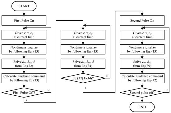
Figure 1.
The complete IGM procedure.
3. Simulation Results
In this section, two simulations are carried out to verify the effectiveness of the proposed IGM. The basic performance of the IGM is shown in the first scenario without course correction, while in the second scenario, a course correction is added in the coast section immediately after the first pulse. A square-inverse gravity model is used in the simulation. The state variables of the interceptor can be obtained from its own inertial navigation system, and information regarding the PIP is calculated and provided by the ground system. It is assumed that all information required for the implementation of the proposed guidance law is obtained without noise during the simulations. The update rate of the guidance command is 10 Hz.
3.1. Simulation Conditions

Table 1.
Initial conditions of engagement.
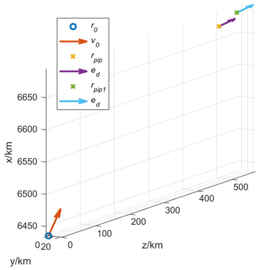
Figure 2.
Initial states of the interceptor and the PIP.
3.2. Scenario 1
In this scenario, a normal IGM guidance procedure is performed, where the guidance command in each guidance cycle is calculated during the whole two pulse sections and the first coast section. The simulation results are shown in Figure 3 and Table 2, where the relative position is defined as . The final position error at the predicted interception time is less than 1 m (measured by distance), and the impact angle error is approximately 1°. The time cost for computing the guidance command in each guidance period is less than 10 ms using a 2.8 GHz CPU.
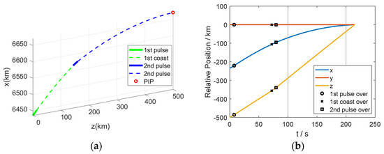
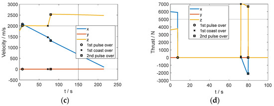
Figure 3.
Curves of the state and control variables of the interceptor in scenario 1: (a) trajectory, (b) relative position, (c) velocity, and (d) thrust.

Table 2.
Results of the proposed method in scenarios 1 and 2.
3.3. Scenario 2
In this scenario, the simulation condition and the IGM guidance procedure in the first pulse section are the same as those in scenario 1, while a corrected PIP information is obtained at the beginning of the first coast section. Hence, a course correction is implemented by using the IGM in this simulation. The simulation results are shown in Figure 4 and Table 2. Compared to the results in scenario 1, the start time of the second pulse is modified (immediately after the first pulse) because of the change in the PIP. The final position error at the predicted interception time is approximately 1 m (measured by distance), and the impact angle error is approximately 6 degrees because the speed increment offered by the second pulse is used for PIP correction rather than impact angle control.
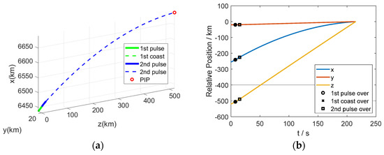
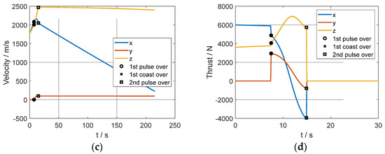
Figure 4.
Curves of the state and control variables of the interceptor in scenario 2: (a) trajectory, (b) relative position, (c) velocity, and (d) thrust.
4. Conclusions
An impact time and angle guidance law is designed for the exoatmospheric midcourse flight of antiballistic interceptors; it covers two pulse sections and two coast sections. The problem is described as an optimal control model with discontinuities in the system equations at interior points, and an IGM is used to efficiently solve the two-point boundary value problem. Simulation results demonstrate the effectiveness of the proposed guidance law; the obtained miss distance accuracy has an order of magnitude of 1 m (i.e., the impact time accuracy has an order of magnitude of 1 ms for a 1 km/s speed target), and the impact angle accuracy has a 1° order of magnitude while the angle can be achieved.
Author Contributions
Investigation, J.R.; Methodology, Y.D.; Supervision, Y.C.; Validation, Y.D.; Writing—original draft, Y.D.; Writing—review & editing, X.W. All authors have read and agreed to the published version of the manuscript.
Funding
This research was funded by China postdoctoral science foundation grant number 2018M643666.
Conflicts of Interest
The authors declare no conflict of interest.
Appendix A
The analytical solution to the two-body problem
can be expressed as
Denoting and , we can derive the orbit elements as
The only time-variant variable is the anomaly, i.e.,
Then, the state variable at time t can be derived as
The partial state derivative can be expressed as the following Jacobian matrix:
where
For , we have
and
For , we have
where
Appendix B
The integration of the state equation under the optimal control law, i.e.,
- I.
- General case (neither nor )
First, we derive the indefinite integral:
We denote that
It can be easily obtained that
Thus,
Note that for optimal control, we have , ; hence,
Additionally, note that , . Thus,
By substituting Equations (A27) and (A28) into Equation (A26) and noting that for our case, we obtain the indefinite integral result for velocity:
and the definite integral result for velocity:
For the position component, we also derive the indefinite integral first:
Denoting that , we have
Considering Equation (A22), we have
where . By using the trick of integration by parts, we have
Note that ; therefore,
Thus,
By substituting Equations (A32) and (A36) into Equation (A31), we obtain the indefinite integral result for position:
and the definite integral result for position:
- II.
- Special case 1 ()
Equation (A19) can be rewritten as
Denote that
Thus, we derive the indefinite integral for velocity:
and the indefinite integral for position:
The definite integrals can be written in the same forms as those in Equations (A30) and (A38).
- III.
- Special case 2 ( and )
Assuming that , Equation (A19) can be rewritten as
Hence, the definite integral for velocity can be derived as
and the definite integral for position can be derived as
References
- Ghosh, S.; Ghose, D.; Raha, S. Composite guidance for impact angle control against higher speed targets. J. Guid. Control Dyn. 2016, 39, 98–117. [Google Scholar] [CrossRef]
- Li, B.; Tang, P.; Xu, H.; Zheng, D. Terminal Impact Angle Control Guidance Law Considering Target Observability. Aerospace 2022, 9, 193. [Google Scholar] [CrossRef]
- Shaferman, V.; Shima, T. Cooperative differential games guidance laws for imposing a relative intercept angle. J. Guid. Control Dyn. 2017, 40, 2465–2480. [Google Scholar] [CrossRef]
- Tekin, R.; Erer, K.S. Switched-gain guidance for impact angle control under physical constraints. J. Guid. Control Dyn. 2015, 38, 205–216. [Google Scholar] [CrossRef]
- Kumar, P.; Dwivedi, P.N.; Bhattacharyya, A.; Padhi, R. Terminal-lead-angle-constrained generalized explicit guidance. IEEE Trans. Aerosp. Electron. Syst. 2017, 53, 1250–1260. [Google Scholar] [CrossRef]
- Wang, X.; Wang, J. Partial integrated guidance and control for missiles with three-dimensional impact angle constraints. J. Guid. Control Dyn. 2014, 37, 644–657. [Google Scholar] [CrossRef]
- Zhao, S.; Chen, W.; Yang, L. Optimal Guidance Law with Impact-Angle Constraint and Acceleration Limit for Exo-Atmospheric Interception. Aerospace 2021, 8, 358. [Google Scholar] [CrossRef]
- Reisner, D.; Shima, T. Optimal guidance-to-collision law for an accelerating exoatmospheric interceptor missile. J. Guid. Control Dyn. 2013, 36, 1695–1708. [Google Scholar] [CrossRef]
- Ye, Q.; Liu, C.; Sun, J. A backstepping-based guidance law for an exoatmospheric missile with impact angle constraint. IEEE Trans. Aerosp. Electron. Syst. 2019, 55, 547–561. [Google Scholar] [CrossRef]
- Horn, H.J.; Chandler, D.C.; Buckele, V.L. Iterative guidance applied to generalized missions. J. Spacecr. Rockets. 1968, 6, 4–8. [Google Scholar] [CrossRef]
- Bryson, A.E.; Ho, Y.C. Applied Optimal Control Optimization Problem for Dynamic Systems with Path Constraints; Blaisdell Publishing Company: Waltham, MA, USA, 1975; Chapter 3. [Google Scholar]
- Chen, Z. Optimality Conditions Applied to Free-Time Multiburn Optimal Orbital Transfers. J. Guid. Control Dyn. 2016, 39, 2512–2521. [Google Scholar] [CrossRef][Green Version]
Publisher’s Note: MDPI stays neutral with regard to jurisdictional claims in published maps and institutional affiliations. |
© 2022 by the authors. Licensee MDPI, Basel, Switzerland. This article is an open access article distributed under the terms and conditions of the Creative Commons Attribution (CC BY) license (https://creativecommons.org/licenses/by/4.0/).