1. Introduction
Flexible cantilever structures are often used in spacecraft structures, such as large antenna structures, large space deployable reflectors and solar panels. In the space environment, the damping is small, and the damping of the flexible structure itself is also small. When it is excited or disturbed by work, such as attitude adjustment and docking, orbit change and solar wind, if the vibration is not controlled, the vibration will last for a long time, which will affect the normal work of the structure and even reduce the service life of the structures [
1,
2,
3,
4,
5,
6].
At present, Euler–Bernoulli beam theory is mainly used in vibration control of beam structure, while Timoshenko beam theory is seldom used for the control difficulties in mathematics. The Euler–Bernoulli classical beam theory has some limitations in structural dynamic analysis, especially in some composite structures. Because the influence of transverse shear deformation and moment of inertia is considered, the analytical results of Timoshenko beam theory are closer to engineering practice [
7,
8]. Therefore, the Timoshenko beam theory begins to be applied in structural dynamics analysis. Based on Timoshenko beam theory and elastic wave theory, Carvalho and Zindeluk [
9] studied the active control of bending waves in infinite Timoshenko beams. Halkyard and Mace [
10] studied the bending vibration feedback adaptive control of beam structures by using wave control method. EL-Khatib et al. [
11] used a tuned vibration absorber to study the bending wave suppression in a beam. Hu et al. [
12] concerned with the control of flexural waves in a beam using a tuned vibration absorber. Su and Ma [
13,
14] compared three analysis methods: Laplace transform, ray and normal mode to study the dynamic transient response of cantilever Timoshenko beam under impact force. Cardoso [
15] blended the Euler–Bernoulli beam theory with idealized transverse shear flows to study a new beam element for aircraft structural analysis. Xing and Liu [
16] studied the dynamic modeling and adaptive boundary control of a three-dimensional Timoshenko beam to realize vibration suppression. Ishaquddin et al. [
17] studied the flexure and torsion locking phenomena in out-of-plane deformation of the Timoshenko curved beam element. Endo et al. [
18] studied a contact-force control problem for a flexible Timoshenko arm. Mei [
19] studied a hybrid approach to active control of bending vibrations in beams based on the advanced Timoshenko theory. Pham et al. [
20] developed a novel dynamic model of a variable-length Timoshenko beam attached to a translating base. The stability of the closed-loop system under the proposed boundary control law was analyzed. Eshag et al. [
21] studied a global sliding mode boundary control method for the Timoshenko beam reduction of the vibration induced by rotation boundary disturbance, uncertainties and distributed disturbance. By using exponential reaching law, the chattering phenomena is avoided. Fleischmann and Könözsy [
22] developed an explicit finite difference numerical method to approximately solve the bending equation of non-uniform fourth-order Euler–Bernoulli beams. The equation has velocity-dependent damping and second-order moments of area, and mass and elastic modulus distribution varying with beam spacing. The method is grid convergent and numerically stable. According to literature studies [
9,
10,
11,
12,
13,
14,
15,
16,
17,
18,
19,
20,
21,
22,
23,
24], it can be seen that the finite element method has become an important theoretical analysis method because it can deal with complex objects and has many general programs. However, the finite element method is more suitable for low-frequency vibration. For medium- and high-frequency vibration, many elements must be divided to accurately describe the vibration characteristics of the system, which will lead to large numerical errors and a sharp increase in the amount of calculation, and the overflow problem will inevitably be encountered when considering vibration control. In addition, enough grid elements must be divided to describe the dynamic characteristics of the structure, the grid of the element is continuously encrypted, and the accumulated error will increase. High requirements for computer hardware configuration are also needed. The modal space control method is to analyze the vibration of the structure from the perspective of the modal. The essence of modal analysis is coordinate transformation. It transforms the coupled motion equations in physical coordinates into modal coordinates for decoupling; thus, as to solve the modal parameters of the system. The above traditional numerical methods can deal with the response of structural vibration well in the low frequency band. However, there are limitations in the medium- and high-frequency bands. With the increase in analysis frequency, it will face many problems, such as the problem of dense and overlapping structural modes.
In this paper, based on Timoshenko beam theory, the vibration control of the cantilever beam is studied by using the optimal traveling wave control method. First, based on Timoshenko beam theory, the modal analysis of the cantilever beam structure commonly used in spacecraft is carried out by using vector vibration mode function, and the system dynamic equation is established. Then, based on the Timoshenko beam theory and the overall motion of the structure, the modal space control method is used to design the global vibration control of the structure. The traveling wave control is used to control the vibration energy flow in the specified area of the structure. According to the local characteristics of the structure, the wave control method is used to absorb the energy carried by the propagating wave in the structural vibration, and the reflection coefficient and transmission coefficient of the wave in the Timoshenko beam when the control torque is applied are obtained. Finally, combined with the advantages of modal space control method, we optimize the traveling wave control method and design an optimized waveform controller to control the rotation angle of the beam. The control results show that the optimized traveling wave control method is better than the traditional traveling wave control method or mode space control method, it and improves the robustness of the system.
2. Structural Dynamic Characteristics of Timoshenko Beam
In engineering practice, it is assumed that the cross-section size of the beam is small compared with its length, thus neglecting the influence of shear deformation and beam section rotation, which is suitable for most members. However, when the ratio of height to span is high or when the composite members are widely used in structures, the effects of shear deformation and cross-section rotation should be taken into account, which have great influence on the higher frequency and mode shape. At this time, Timoshenko beam theory needs to be used. The cantilever Timoshenko beam structure studied in this paper is shown in
Figure 1.
It is assumed that the rotation angle of the cross section produced by the bending moment
is
. If there is no shear deformation, the cross section is perpendicular to the elastic axis, and
Ψ equals the slope of the elastic axis. When shear deformation is taken into account, the rotation angle generated by shear force is
γ. The actual cross section angle is
; then, we can obtain:
The angle
and
meet the following relationship:
where,
respectively represent the elastic modulus, the moment of inertia of the beam section, the shear conversion coefficient, the shear modulus and the section area, and
, in which
are respectively the section height and the Poisson’s ratio of the material.
Respectively,
denoted the mass density, transverse load and bending moment of the beam. Considering the equilibrium of the beam element, the following equilibrium equations can be obtained.
Substituting Equation (2) into Equation (3), we can obtain:
The bending moment and shear force in a beam are expressed as:
where
is the bending stiffness of beams,
,
is the shear modulus.
Equation (4) can be written in matrix form as follows:
where
is the generalized displacement,
are the deflection of beam and angle of rotation, respectively;
is the generalized mass;
t is the time;
;
is the external disturbance dynamic vector, and the expression of
is
In order to analyze the frequency characteristics of the beam and consider the free vibration state of the beam, the following equations can be obtained by decoupling the displacement
and the rotation angle
in Equation (4):
Equation (7) above shows two degrees of freedom of the Timoshenko beam: the free vibration characteristics of deflection and rotation angle are exactly the same, that is, the modes of corresponding order, both of which have the same frequency and wave number . In Equation (7), the first and second items denote the basic conditions of vibration, the third and fourth items denote the effect of the cross section moment of inertia and shear deformation, respectively, and the last item denotes the coupling effect of moment of inertia and shear deformation.
3. The Simulation Results and Discussions in the Deorbiting Process
For flexible structures, the low frequency modes are dense; thus, it is difficult to design the controller directly by physical coordinates. In the modal space, the vibration control of the structural system can be transformed into a small number of modal coordinate vibration controls. The response of the structure can be expressed as the sum of infinite modes:
where
is the
ith-order mode function,
is the
ith-order modal coordinates, and
is number of modal truncation.
By deriving Equation (4) from time variables and space variables, the following equation can be obtained at the left end of Equation (4) as:
Substituting Equation (9) into Equation (6), we can obtain:
where
is the modal vibration function and should satisfy the homogeneous differential equation as follows:
Then, the frequency characteristics of the system are analyzed. Assuming
, and substituting into (7) to obtain:
where
is the elastic traveling wave number of classical Euler beam and
k is the wave number of the modal vibration function
.
When the vibration frequency of the beam is
, the elastic wave number is
, which indicates that there are two pairs of propagating waves in the structural beam, and the phase velocity is
. When the vibration frequency of the beam is
, the elastic wave numbers are
and
, which indicate that there are a pair of propagating waves and a pair of attenuation waves in the structural beam. Where
denotes the transition critical frequency of the extended state and the local state. Because the structure vibration can be regarded as the superposition of multiple reflection of the elastic wave mode, the propagation wave can form the whole vibration of the finite region of the structure, while the attenuation wave forms the localized vibration in the finite area of the structure. Thus, in the beam, a main vibration mode function is determined when a set of wave numbers
and
corresponding to the natural frequencies are determined.
To study the cantilever beam, use the modal coordinate equation of the beam.
where
,
is the external disturbance force.
The essence of independent modal control is to reconfigure the poles of the vibration system by state feedback; thus, the state space description of the system is established first. Assuming the modal control force is
, for the vibration system:
Considering the control of the pth-order mode, and introducing the state vector
, where
, the controlled partial state equation of the system is expressed as follows:
where
In Equation (16), the 0 and I are a zero matrix and a unit matrix, respectively;
,
are the modal control force and the modal disturbance force, respectively. When the controllability matrix
, based on the linear system theory, we know that the state of the system is completely controllable, and the pole can be arranged arbitrarily. Introducing the state feedback, the control force
is given as follows:
The closed-loop dynamic equation of the system (15) is as follows:
According to Equation (18), the characteristic structure of the original vibration system can be changed arbitrarily by adjusting the feedback gain .
Considering point force control input
, point force disturbance input,
in physical coordinates, where
p,
n are respectively the number of controlled modes and the number of disturbance forces, and the
jth-order mode control force
and disturbance force
are expressed as follows:
where the control input force vector is
, and the disturbance input force vector is
. Thus, the transformation relations of the force vectors between the modal coordinates and the physical coordinates are written as follows
There is no corresponding relation between the position coordinates xi of the above two equations, that is, the position of the control force and the disturbance force is not necessarily the same; and the selected position coordinates should at least ensure invertible.
Substituting Equation (20) with Equation (15), the state equation of the controlled part can be obtained as follows:
where
where
are the generalized displacement gain of the modal control and the generalized velocity gain matrix, respectively. It is obvious that the modal structure of the system is reconstructed by state feedback, and the modal damping and stiffness of the system are improved effectively.
The state equation of the part of the uncontrolled mode should be:
where
The deflection
at the position coordinate
is selected as the output of the system, and the following results can be obtained from Equation (8);
The final output of the system is:
where
Equations (21), (23) and (26) constitute a complete state space description of partially controlled vibration systems. It is clear that the controlled and uncontrolled modes are independent of each other.
4. Rotating Angle Traveling Wave Control of Timoshenko Beam
Vibration in structure is essentially the propagation of elastic wave in structure. An elastic wave can be regarded as the representation of vibration propagation in a continuous medium. When an elastic wave propagates in a bounded structure and various waveforms are superimposed and stable, its external performance is often regarded as a vibration. Structural vibration is a special form of wave expression, which can be regarded as the result of the superposition of traveling waves satisfying certain conditions. Therefore, the vibration of the structure can be regarded as the propagation, reflection and transmission of the elastic disturbance in the structure, and the whole structure shows a wave characteristic. Therefore, the dynamic response and vibration control of a missile structure can be studied from the perspective of a traveling wave. The vibration in the structure can be described by the superposition of wave modes. The active control method of a traveling wave is to control the energy propagation in the structure, that is, to reduce the transmission from one part of the structure to the other, or to absorb the energy carried by the traveling wave. In wave control, the control law is the transfer relation between the input and output of the controller. It can be divided into time domain design method and frequency domain design method. The control force can be a point force or a point moment. The frequency domain design method is used here. In this paper, a wave controller is designed to control the rotation angle of the beam, and the wave control torque is applied when the rotation angle is controlled.
There are two methods to describe vibration: modal mode description and wave description. In essence, the former belongs to standing wave expression, while the latter is traveling wave expression. Considering the free vibration of the Timoshenko beam, the time factor
is omitted:
In the above equation, and represent the positive and negative propagation waves, respectively. The modes with spatial factors and represent the propagating waves carrying energy, while the modes with spatial factors and represent the local vibrational modes that do not carry energy. The purpose of wave control is to dissipate and absorb the energy in the propagating wave. When there are no discontinuous points in the infinite beam structure, the above elastic waves will propagate to infinity, and the local vibration modes will decay quickly.
Considering the existence of excitation force in beam structure (shear discontinuity point), according to the traveling wave theory, the reflection and transmission of the elastic wave will occur at the discontinuous incidence. Assuming that a sequence of forward propagating waves is incident at
, resulting in reflected, transmitted and near-field waves, the displacement of the beam at
and
is as follows
In the feedback wave control, the sensor and actuator are located in a certain area of the structure to control the propagation of elastic wave. In this case, the control force is a discontinuous point. In the frequency domain feedback wave control, the applied wave control moment is taken as
According to the conditions of generalized displacement continuity and generalized force equilibrium, the function of beam satisfies at
x = 0
In Equation (28), is the transfer function of the wave controller, and the symbols and represent the corresponding mechanical quantities of the beam at and , respectively.
According to the expressions of bending and shear forces, Equation (28) can be written as
where
Denoted as
,
, the following equation can be obtained:
It is the same as the method of the wave controller designed to control the lateral displacement, denoted as . The energy reflected and transmitted by unit incident energy is . The maximum energy dissipation in discontinuous structure is taken as the performance index of optimal control, and the optimal control law is determined.
When
reaches the minimum, the feedback gain is
where
The corresponding reflection and transmission coefficients of incident waves are expressed as follows, respectively:
If the wave control moment is applied at the point
, the tuning PD control becomes:
At this time, wave control Equation (34) is applied to the original vibration system, and the matrix form of the motion equation of the system is written as follows:
where
,
,
,
,
are mass matrix, damping matrix and stiffness matrix, respectively, and the expressions of them are as follows:
where
It is important to note that
will also be a matrix, not a number, in subsequent programming calculations. For ease of use in optimized control, we can also write
in block form:
When there is no wave control force, the mass array M is identity matrix, C is the zero matrix, K is diagonal matrix with the square of natural frequency. However, the wave control moment is coupled with the vibration modes of the uncontrolled original system, and the mode of the wave control system changes as a result.
Introducing the state vector
, Equation (39) is written in the form of a state space:
where the coefficient matrix is:
6. Numerical Example and Analysis and Discussion
Using the independent modal space method and optimized control method, the dynamic response of the structural beam subjected to control force is investigated. Taking the characteristic length as the length of the beam
l, the following dimensionless quantities: Poisson ratio
; high to length ratio
; damping factor before control
;
;
is the elastic traveling wave number corresponding to the
ith-order natural frequency.
Table 1 shows the first 10 dimensionless natural frequencies of the Timoshenko beam.
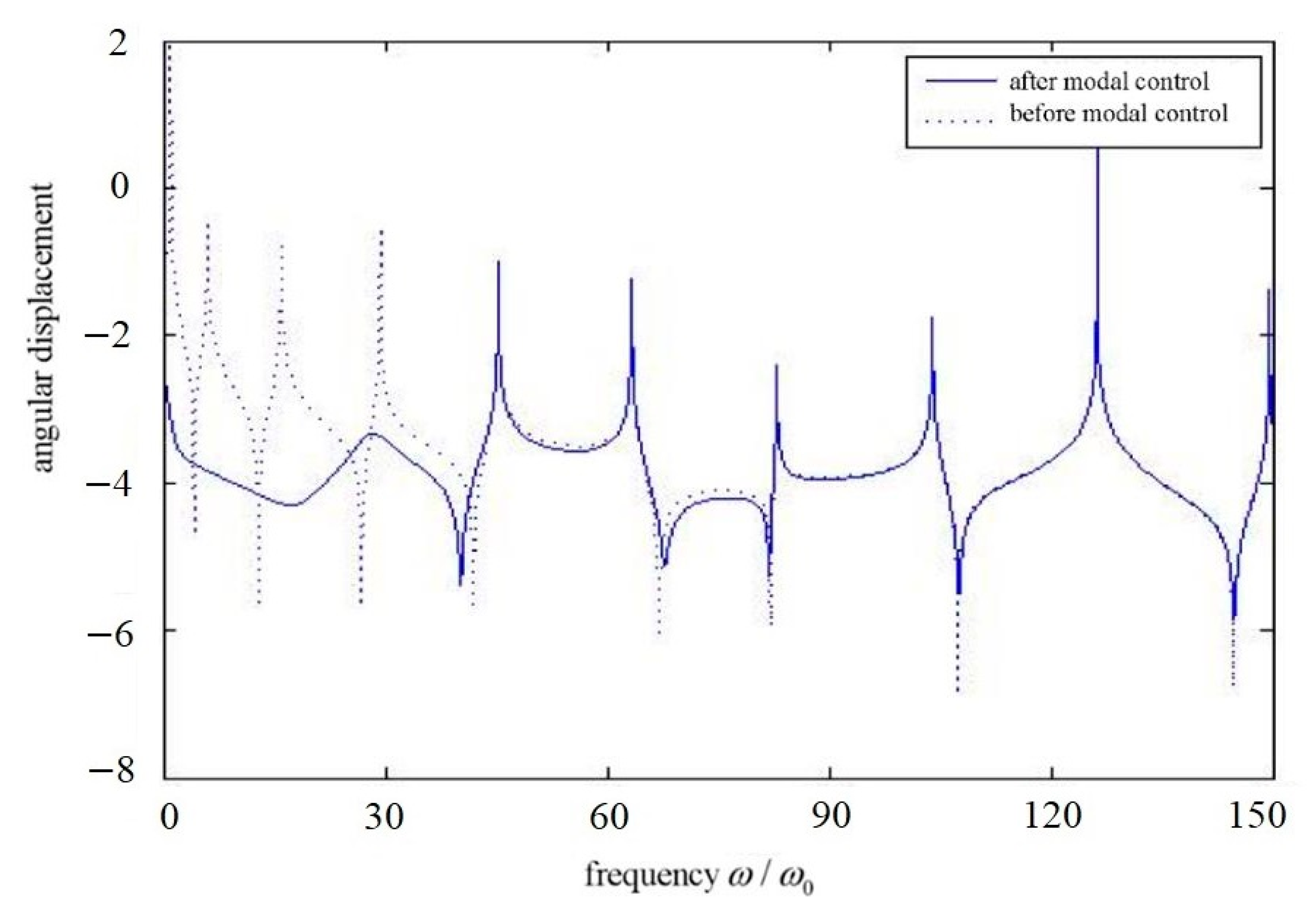
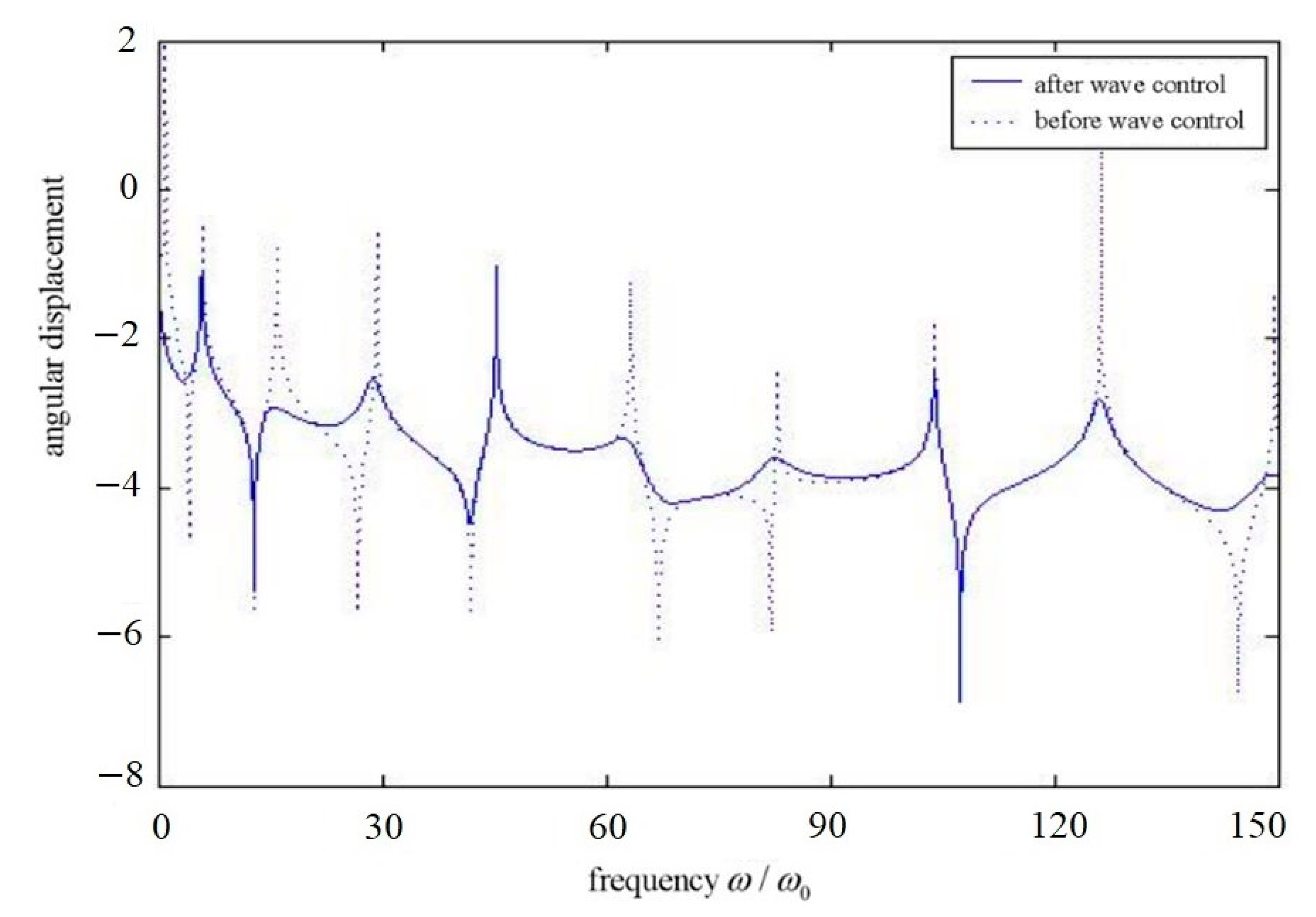
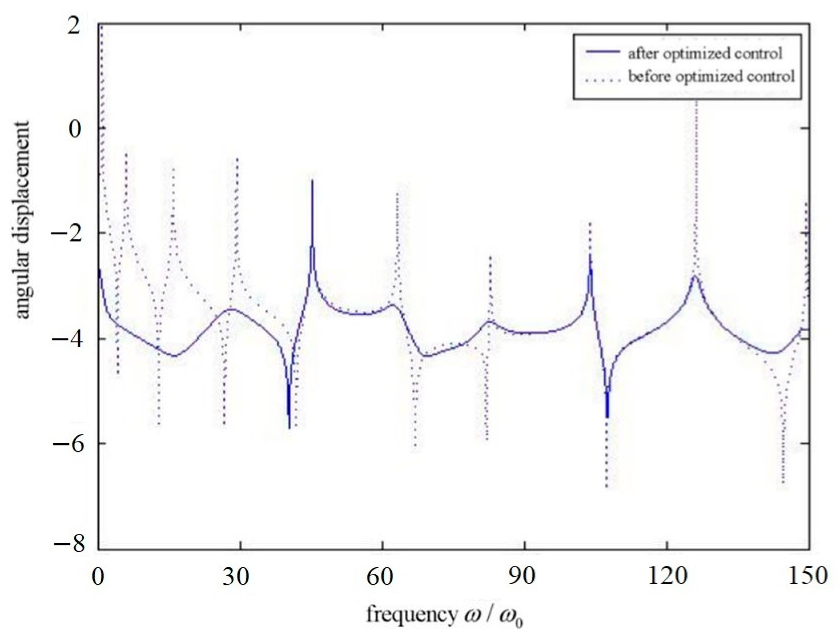
Figure 2,
Figure 3,
Figure 4,
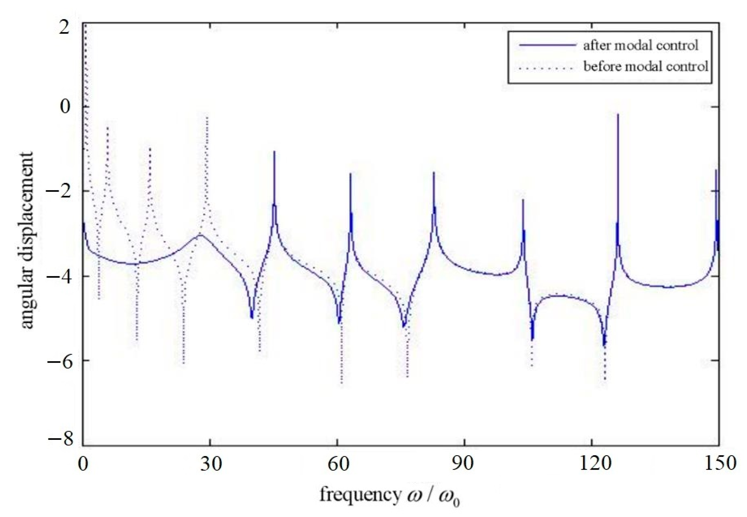
Figure 5,
Figure 6 and
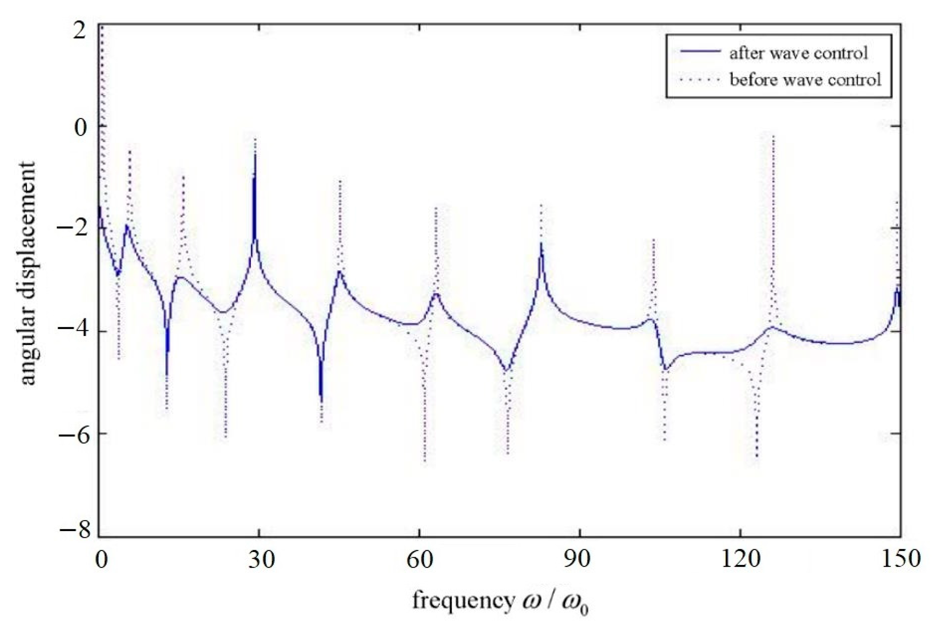
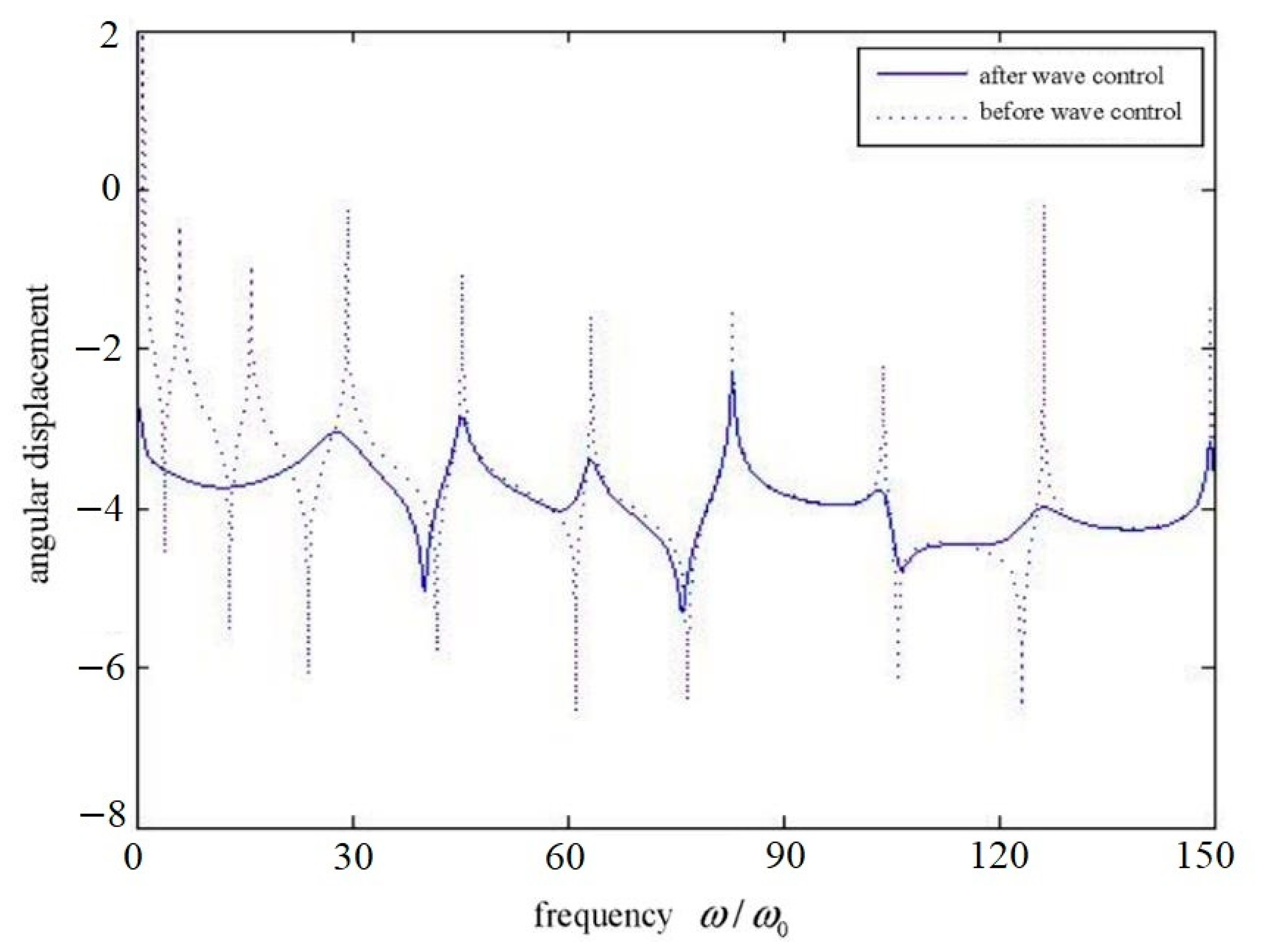
Figure 7 show the frequency response of the structure before and after the control with three different control methods under different parameters. In
Figure 2,
Figure 3,
Figure 4,
Figure 5,
Figure 6 and
Figure 7, the horizontal coordinates are dimensionless frequency values, while the vertical coordinates are the common logarithmic values of the frequency response. In
Figure 2,
Figure 3 and
Figure 4, the position of disturbance action is
.
Figure 2 shows the frequency response before and after modal control; the positions of mode control force applied are
,
,
,
; the first four modes are controlled, and the measuring position of the dynamic response is
, where the occurrence point of the maximum value of the total deflection of the first 10 modes is.
Figure 3 shows the frequency response of the structure before and after the control when the position of the wave control force is
.
Figure 4 describes the frequency response of the structure before and after the traveling wave/modal-optimized control.
In
Figure 5,
Figure 6 and
Figure 7, the position of disturbance action is
.
Figure 5 shows the frequency response before and after modal control. The positions of the modal control force applied are
,
,
,
, the first four modes are controlled, and the measuring position of dynamic response is
, where the occurrence point of the maximum value of the total deflection of the first 10 modes is.
Figure 6 shows the frequency response of the structure before and after the control when the position of the wave control force is
, and
Figure 7 describes the frequency response of the structure before and after the travelling wave/modal-optimized control.
When applying the wave control force, the node of the first 10 mode vibrations should be avoided as much as possible. The frequency responses of the single-use wave control, independent mode space control and the optimized traveling wave control, including the controlled and uncontrolled frequency response, are compared. In the approximation of the optimized control method, the controller is tuned to the optimum at the fifth mode. In the case of the independent modal space control, the first four-order damping factor of the structure is increased to 0.1 by using the pole assignment method. Through the analysis, we can obtain the discussion as follows:
Figure 2 and
Figure 5 show that modal control has good control effect on low-order modes of structure, and it has good independence and has little effect on other modes; thus, the rapid change of the uncontrolled modal response still exists.
Figure 3 and
Figure 6 show the frequency response of the structure before and after the use of the wave controller. The response of the structure before the control is sharp, but the wave control can be regarded as adding damping to the structure, absorbing the energy in the structure, and the sharp response is weakened. The figure also shows that the modal characteristics of the whole structure have changed after the wave control; that is, the natural vibration frequency has changed. Finally, we can see that the position of the wave controller is different for the control effect of each mode frequency.
Figure 4 and
Figure 7 show the frequency response of the structure before and after using wave control and independent mode space control. It reflects the excellent control effect of the optimized control. Because the optimized control combines the characteristics of the former two methods, that is, the wave control can control the response at higher frequencies better, and the independent modal space control can effectively control the first four modes. It makes up for the poor control effect of wave control at low frequency. Therefore, the performance of using one of the above controls alone is improved.

