Abstract
The real-time fault detection and diagnosis algorithm of a liquid rocket engine is the basis of online reconfiguration of guidance and the control system of a launch vehicle, which is directly related to the success or failure of space mission. Based on previous related works, this paper carries out comparative experimental studies of relevant intelligent algorithm models for real-time fault detection engineering application requirements of a liquid hydrogen–oxygen rocket engine. Firstly, the working state and detection parameters’ selection of a hydrogen–oxygen engine are analyzed, and the proposed three real-time intelligent fault detection algorithm model design methods are elaborated again. Fault detection calculation and analysis are carried out through normal test data and fault test data. The comparative analysis results of real-time intelligent fault detection algorithm models is presented from three dimensions: detection time, fault detection, and stability and consistency. Finally, based on a correlation analysis, a comprehensive intelligent fault diagnosis model design framework is given to further solve the requirements of real-time fault detection and diagnosis engineering development of a liquid rocket engine, a complex piece of equipment.
1. Introduction
A liquid rocket engine (LRE) is the core of flight power of a carrier rocket system. Its performance determines the overall performance of the carrier rocket, which is directly related to the success or failure of a space mission. LRE is a complex thermal fluid dynamic system formed by cross-coupling of many different independent dynamic links [1,2]. It works in extremely harsh environments, such as ablation of high pressure, high temperature and high-speed airflow, erosion of propellant components, high-frequency oscillation, etc. [3]. The working conditions are close to the physical limit of materials. Any minor anomaly can quickly develop into a highly destructive failure, leading to the failure of the launch mission and huge economic losses. With the development of information technology and artificial intelligence algorithms, integrating artificial intelligence technology into smart rockets has become the development trend of the new generation of carrier rockets [4,5]. On the one hand, research on intelligent fault detection technology of an LRE can effectively improve the reliability and safety of an LRE, avoid accidents as much as possible, and also help researchers improve the structure and performance of the engine. On the other hand, intelligent fault detection of an LRE is an important part of a smart rocket. It is an indispensable part of the rocket that will learn in the future and has very important engineering application value. Since the 1970s, the United States and the former Soviet Union [6,7] have developed various LRE fault detection and diagnosis systems, and the United States has widely applied the relevant research results to the space shuttle main engine (SSME) [8,9,10,11,12,13,14].
So far, as the foundation of a rocket engine fault detection system [15], LRE fault detection technology has been developed, which can be roughly divided into three stages [16]. In the first stage, some important sensor parameters are measured by professionals with engineering experience to judge the working state of the engine. In the second stage, the fault detection technology based on signal processing and modeling analysis is developed with the development of sensor technology. In the third stage, the intelligent fault detection technology with data mining, deep learning, and information fusion are the core. Wang et al. [17] made an in-depth analysis of relevant fault detection methods and summarized the development of three types of fault detection methods for LRE. With the development of computer technology, fault detection technology based on artificial intelligence algorithms has emerged. The fault detection method does not need to establish an accurate mathematical model but analyzes the performance of the engine based on historical data of sensors, which has become an important means of effective fault detection. Moonis et al. [18] developed an expert system for fault diagnosis for SSME. Gupta et al. [19] designed a real-time fault diagnosis expert system named LEADER for SSME. Flora et al. [20] proposed a neural-network-based LRE sensor fault detection, isolation, and replacement algorithm. Soon-young et al. [21] proposed a deep-learning-based fault detection and diagnosis method in the LRE start-up stage using long short-term memory and CNN. Zhu et al. [22] provided steady-state process fault detection based on a convolutional auto-encoder and a one-class support vector machine for LRE.
When there is a real-time requirement for computing speed and relatively limited computing resources, there are still some difficulties in applying the existing artificial intelligence algorithms to the actual engineering applications of LRE fault detection. In this paper, aiming at the engineering requirements of real-time fault detection for a certain type of liquid hydrogen and oxygen rocket engine, on the basis of previous research work, the three proposed kinds of real-time intelligent fault diagnosis algorithms, based on an adaptive genetic algorithm to optimize a neural network [23], on a quantum genetic algorithm to optimize a neural network [24], and on the optimization of least squares support vector regression [25], were analyzed. The overall structure of the paper is roughly arranged as follows: Section 2 explains the working state machine detection parameter selection of the hydrogen–oxygen engine. Section 3 gives the design and application flow of three intelligent fault diagnosis algorithms. In Section 4, the relevant test data calculation and comparison analysis of five fault detection models including BP, GA-BP, AGA-BP, QGA-BP, and GA-LSSVR are carried out, and the fault diagnosis algorithm framework of multi-algorithm fusion is proposed for future development. Section 5 summarizes the comparative study of artificial intelligence algorithms for real-time fault detection of a hydrogen–oxygen rocket engine in this paper.
2. Hydrogen–Oxygen Engine and Parameter Selection
In this paper, a comparative study of real-time intelligent fault detection methods for a new type of liquid hydrogen liquid oxygen rocket engine is carried out. The 50-ton oxygen-hydrogen rocket engine YF-77, the first-stage rocket engine of Long March 5, adopts the gas generator cycle scheme of a single thrust chamber and a parallel twin turbopump, and the ground thrust of the single engine is 52 tons and the vacuum thrust is 70 tons [26]. The previous work of this paper has described the system structure and working process of a liquid hydrogen and liquid oxygen rocket engine in detail [25].
There are three main working states when the LRE works, which are the starting state, the steady state, and the shutdown state. (1) Starting state: The start-up phase refers to the process when the LRE receives the boot instruction and starts working until the various operating indicators of the system enter the main level working condition. The starting process of an LRE is a nonlinear time-varying random process, which needs to complete the opening and closing of the valve and the sudden rise of the turbine and pump speed in a very short time, and the variation range and rate of various physical parameters are large. (2) Steady state: In this stage, the relevant parameters of the LRE are in a preset state, and the relevant measurement data are generally in a stationary state. In this stage, if an engine condition adjustment is required, the relevant sensor measurement data will fluctuate. (3) Shutdown state: The LRE receives the shutdown command, all kinds of valves are closed, and the relevant propellant connection is disconnected until the engine thrust is reduced to zero, and the engine shutdown is completed. The proposed real-time fault grace detection algorithm test focuses on the steady-state working phase of the LRE.
The basis of LRE fault detection is that when the rocket engine is working, sensors measure a large number of different types of parameters about the engine, and researchers analyze the working state of the engine based on the relevant sensor data. Generally, the information measured by the sensors [27] includes information reflecting the working state of the engine, such as pressure, temperature, and flow rate; information reflecting the working mechanism of the engine, such as frequency, spectrum, etc.; information that reflects the mechanical structural characteristics of an engine, such as stiffness, damping, etc. Vibration, pressure, temperature, and flow are usually used to detect LRE faults.
In this paper, based on the sensor measurement signals of a new type of hydrogen–oxygen rocket engine real-time intelligent fault detection methods suitable for a certain type of engine are designed, and LRE fault detection methods are verified and analyzed. The usage of fault monitoring parameters includes hydrogen pump temperature (S1), oxygen pump after temperature (S2), the temperature of the gas generator (S3), generator hydrogen injection pressure (S4), oxygen generator before injection pressure (S5), hydrogen pump inlet pressure before (S6), hydrogen pump outlet pressure (S7), oxygen pump inlet pressure (S8), oxygen pump outlet pressure (integrated), combustion chamber pressure (S10), and gas generator pressure (S11).
3. Model Design of Three Real-Time Fault Diagnosis Algorithms
3.1. Detection Threshold Determination Method
In the study of real-time fault detection and diagnosis of an LRE based on an intelligent algorithm, the setting of fault detection threshold is often manually determined according to experience. The setting of detection threshold has a great impact on the reliability and sensitivity of LRE fault detection [28,29], and the threshold directly affects the accuracy of the fault detection system. If the threshold is too small, it will easily make the detection system too sensitive and increase the possibility of false positives. If the threshold interval is too large, the fault detection system is prone to a large delay, which reduces the sensitivity of the fault detection system and leads to missed detection.
Assuming that is the parameter value measured by a sensor during the normal operation of an LRE, for an LRE with different stages and working conditions, the measured parameter cannot be completely the same. Obviously, is a random variable. According to Chebyshev’s inequality, for any ,
where is the mean value of sensor parameters at different times under normal test conditions, and is the standard deviation of sensor parameters at different times under normal test conditions. For the parameter, the mathematical expectation , the variance is .
According to Equation (1), for a given false detection probability , the normal value interval of parameter is:
where . According to the literature [30,31], the probability of the value of the fault prediction parameter following a normal distribution in the interval is 99.74%. Therefore, in the fault detection method of this paper, the value of n is 3.
Due to an LRE in the process of working, the random disturbance factor can bring certain interference to a fault detection system. It may be moment monitoring sensor data related to too much change, more than the threshold line, particularly prone to the engine start phase. Therefore, in order to guarantee the stability of the test results, the logic of an engine malfunction was amended as: If the relevant parameters exceed the set threshold for five consecutive times, it is considered that the engine is faulty; otherwise, it is considered that the engine is interfered by accidental factors. Because the current collection frequency of engine-related sensor data was quite high, and the processing data of the model was fast enough, the requirement that the relevant monitoring data continuously exceed the fifth power to trigger the fault alarm will not affect the real-time performance of the fault detection system.
3.2. BP Neural Network Is Optimized Based on an Adaptive Genetic Algorithm
By using an AGA to optimize the weight and bias of the BP neural network, the neural network can converge faster, improve the accuracy of the fault detection model, and reduce the operation time of the fault detection model. The fault detection method based on the AGA-optimized BP neural network fault detection model (hereinafter referred to as AGA-BP) was as follows: firstly, the fault detection model is trained with the historical test data of the engine in normal working conditions. Then, the measured sensor data of the LRE to be tested are taken as the input of the model, and the trained AGA-BP model is constructed. The predicted value of the engine at this time is determined with the sensor under test; then, the predicted value and the engine run under the current moment, comparing the actual sensor measurement value with the residual . Finally, the residual is compared with the preset threshold value , and it is determined whether there is an engine fault. This achieves the purpose of real-time engine fault detection. The principle of the fault detection method of the AGA-BP model is shown in Figure 1.
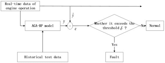
Figure 1.
Principle of the fault detection method for the AGA-BP model.
3.3. BP Neural Network Is Optimized Based on a Quantum Genetic Algorithm
The weights and bias values of the BP neural network are optimized based on a QGA. The algorithm steps are designed as follows:
Step 1: QGA considers the weight and bias of the BP neural network as a chromosome. The chromosome length is , and chromosomes encoded by quantum bits are randomly generated to form the initial population.
where is evolved to the generation when the population is individuals.
Step 2: The initial population is measured once, and the corresponding binary code is obtained.
Step 3: The fitness of the above solutions is evaluated. The obtained binary code is converted into a decimal array, and the corresponding values are extracted according to the rules to obtain the corresponding weights and biases. The BP neural network is used to fit the training set, and the weights and biases and the corresponding fitness values under the current best fitness are retained, that is, the individual is optimal.
Step 4: The population is updated by a quantum rotation gate evolution operation.
Step 5: Whether the evolutionary requirements are met or not is judged. If not, step 2 is returned to and updated iteratively to obtain the optimal BP network weights and biases.
The process of optimizing the BP neural network based on QGA is shown in Figure 2. The basic train of thought when using a QGA to optimize the BP neural network based on an LRE real-time fault detection method (hereafter called QGA-BP) and an LRE based on an AGA-BP real-time fault detection method is almost the same: first of all, gather LRE-based real-time sensor data and establish the model of the fault detection assessment model to calculate the output state of the system. Then, the output of the detection model is compared with the actual sensor output value to obtain the residual value, which is used as the basis for the current state of the engine system. The fault detection method based on QGA-BP is shown in Figure 3.
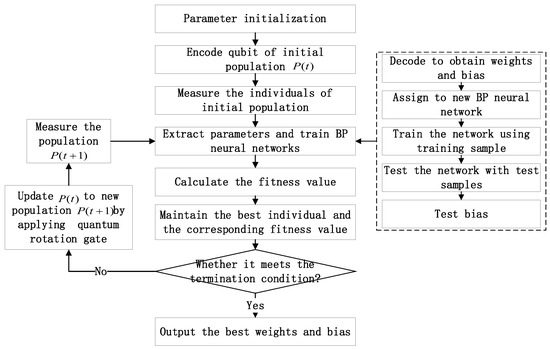
Figure 2.
Optimization of a BP neural network by a quantum genetic algorithm.
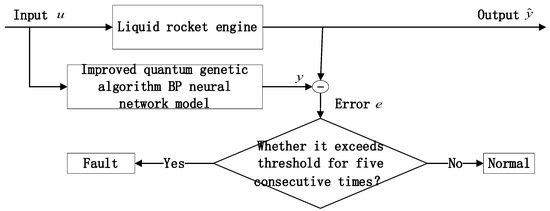
Figure 3.
Fault detection method based on a quantum-genetic-algorithm-optimized BP neural network.
3.4. Optimized Least Squares Support Vector Regression Based on a Genetic Algorithm
Different types of kernel function have little influence on SVR performance, but the selection of kernel function parameters has great influence on SVR performance. For SVR, it is needed to determine the main parameters of the punishment factor , RBF kernel parameter , and not sensitive loss factor . Here, influences the generalization ability of training, influences the distribution of sample data that are mapped to a high-dimensional space, and determines the number of the support vector regression model, which affects the training accuracy and the convergence speed of the algorithm. Common methods to determine the parameters include the empirical method, the grid search method, and the optimization method based on various intelligent algorithms. The empirical method needs to set parameters according to the user’s experience and puts forward higher requirements to the user. The grid search method searches the parameters of SVR in a certain range, while the optimization method based on various intelligent algorithms regards the parameter setting problem as a problem of seeking the optimal solution and obtains the optimal parameter setting value by solving this problem. This section mainly discusses the optimization of punishment factor and RBF kernel parameters . Firstly, the grid search method is used to find the appropriate parameters, and then the genetic algorithm is used to search nearby to set the best LSSVR parameters.
Define the range of LSSVR optimal parameters: , . In this range, the genetic algorithm is used to optimize the parameters in order to obtain more suitable LSSVR parameters. The flow chart of optimizing LSSVR based on a genetic algorithm is shown in Figure 4, and the specific steps are as follows:
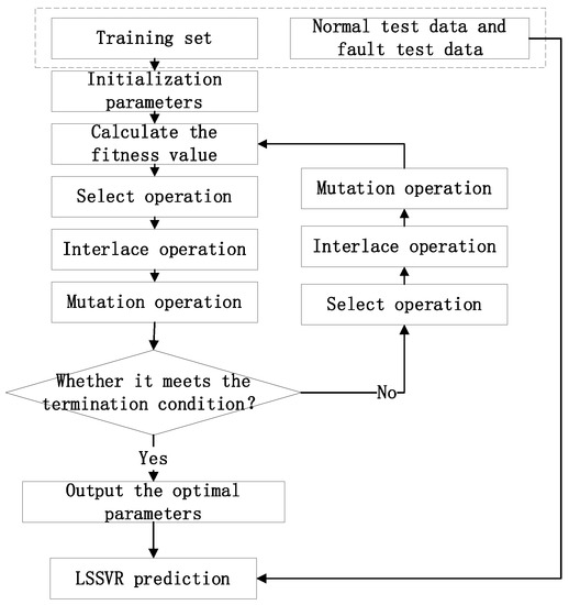
Figure 4.
Flow chart of GA-LSSVR.
Step 1: The parameter codes that need to be optimized for LSSVR are binary-coded to form chromosomes, and the population is initialized.
Step 2: The chromosomes in the population are decoded to obtain the parameter values of LSSVR, the parameter values are used to train the LSSVR model, the fitness value of each chromosome is calculated, and the best fitness obtained in the contemporary population and the corresponding parameters are recorded.
Step 3: The selection operation, crossover operation, and mutation operation are performed on the population.
Step 4: The newly obtained population is decoded, the fitness value is calculated, and whether the termination condition is satisfied or not is judged; if not, step 3 is continued.
Step 5: The obtained optimal LSSVR parameters are output.
The parameters of the GA in this section are set as follows: the maximum number of evolution generations is 200, the number of populations is 20, the crossover probability is 0.9, and the mutation probability is 0.1. An optimized calculation got the best parameters of the current model of c = 0.34969, g = 0.014954.
After the suitable parameters of LSSVR are obtained by using a genetic algorithm, a fault detection model of a liquid rocket engine based on genetic-algorithm-optimized LSSVR (GA-LSSVR) is established. The principle for sensor information input will be a real-time LRE-measure-trained GA-LSSVR model based on historical test data. The engine of the sensor forecasts the output and then gets the actual output of the engine at the moment when it is poor, the residual value is estimated, and then the residual values and setting threshold are compared. The current working state of the engine is thus determined. The fault detection process of an LRE based on GA-LSSVR is shown in Figure 5.
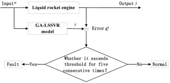
Figure 5.
Fault detection flow of a liquid rocket engine based on GA-LSSVR.
4. Comparative Analysis of Fault Detection Methods
The fault detection methods proposed above for this type of liquid hydrogen liquid oxygen rocket engine can carry out real-time fault detection under the current conditions, but different fault detection methods have certain differences in realizing working state monitoring of this type of engine. In this section, the performance of the three intelligent fault detection algorithms proposed above is compared with that of traditional BP and GA-BP algorithms for fault detection of this type of engine. The algorithms’ software environment for the comparisons was MATLAB R2020b, and the hardware for the computations was, respectively, i7-10700 2.90 GHz and 64 GB.
4.1. Normal Test Data Fitting Test
The BP, GA-BP, AGA-BP, QGA-BP and GA-LSSVR fault detection models were compared with the normal test data of the rocket engine. Figure 6 shows the fitting output of the BP, GA-BP, AGA-BP, QGA-BP, and GA-LSSVR models for normal test run data of this type of hydrogen and oxygen rocket engine, and Figure 7 shows the corresponding residual graph.
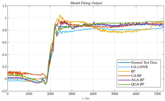
Figure 6.
BP, GA-BP, AGA-BP, QGA-BP, GA-LSSVR fitting output: normal test data.
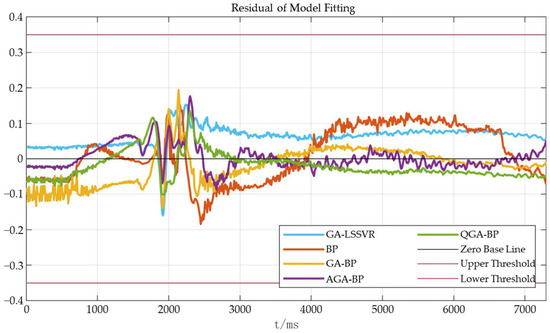
Figure 7.
BP, GA-BP, AGA-BP, QGA-BP, GA-LSSVR fitting residual diagram: normal test data.
It can be seen from Figure 6 that the five fault detection models described could reasonably fit the normal test data of this type of liquid hydrogen liquid oxygen rocket engine. In combination with Figure 7, it was noticed that in the five fault detection models there were some severe fluctuations in the identification of the engine’s starting stage and the stable stage, but in the fitting of the subsequent stable state, the performance was relatively stable. In the prediction fitting of the stable stage of the current engine test data, on the whole, the GA-LSSVR fault detection model was more stable than the other four fault detection models in the fitting of the normal test data were. The fitting residual values of the normal test data corresponding to the five fault detection models used for this engine were all ±0.2, and the threshold setting of 0.35 met the detection requirements of the normal test state, and no misdiagnosis occurred.
4.2. Fault Test Data Fitting Test
Figure 8 and Figure 9 show the fitting output of BP, GA-BP, AGA-BP, QGA-BP, and GA-LSSVR models and the corresponding residual maps under fault test data of this type of engine. It can be seen from the figure that these five fault detection models could effectively detect faults when identifying the fault data of this type of engine under the threshold of 0.35.
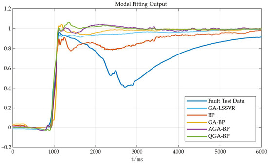
Figure 8.
BP, GA-BP, AGA-BP, QGA-BP, GA-LSSVR fitting output: fault test data.
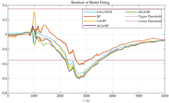
Figure 9.
BP, GA-BP, AGA-BP, QGA-BP, GA-LSSVR fitting residual diagram: fault test data.
It was noted that, similarly to the fitting of normal test data, there was a certain degree of fluctuation from the engine’s starting stage to the stable stage, especially in the GA-BP fault detection model, which had relatively sharp fluctuation. If the threshold was improperly set, it was easy to send out a false alarm.
4.3. Comparative Analysis of Algorithm Performance
Five fault detection models—BP, GA-BP, AGA-BP, QGA-BP, and GA-LSSVR—were used to compare and analyze the normal test data and fault test data of this type of rocket engine. Table 1 shows the fault detection performance of these five liquid rocket engine fault detection models in the simulation test above. It was compared in three dimensions of detection time, fault detection, and stability consistency.

Table 1.
BP, GA-BP, AGA-BP, QGA-BP, and GA-LSSVR fault detection performances.
4.3.1. Compared Models’ Performance in Terms of Detection Time
In the current computing environment, it was checked under the two test tracks whether it was the detection of normal test data or fault test data (in which 730 data points were collected for normal test data and 6001 data points were collected for faulty test data). The total fault detection time of BP, GA-BP, AGA-BP and QGA-BP models was in the order of milliseconds. The fault detection time of the GA-LSSVR model was longer than that of other models, but it also met the requirements of real-time fault detection and the control cycle of this type of engine. Figure 10 compares the detection time of the five fault detection models.
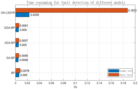
Figure 10.
Comparison of fault detection time of different models.
From the point of view of detection time, the five fault detection methods all met the real-time fault detection engineering requirements of this type of liquid hydrogen liquid oxygen rocket engine, and the corresponding detection period met the control and regulation period of this type of rocket engine, which can be used in practical engineering detection.
4.3.2. Compared Models’ Performance in Terms of Fault Diagnosis Accuracy
The above analysis indicates that BP, GA-BP, AGA-BP, QGA-BP, and GA-LSSVR fault detection models could detect faults when fault test data were detected. Figure 11 is the local enlarged view of the fault detection position as shown in Figure 9. It can be seen that the sequence of fault warning issued by the five fault detection models was AGA-BP, QGA-BP, GA-BP, GA-LSSVR, and BP. In addition, it was noted that under the current fault threshold standard of 0.35, the data points detected by the GA-BP, AGA-BP, QGA-BP, and GA-LSSVR models were not very far away from the fault test data, which can send out early warning information faster than the BP model could.
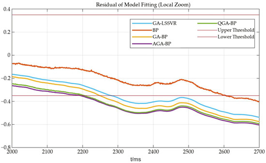
Figure 11.
Fault test detection (Figure 9) local amplification (2000–2700).
From the perspective of fault detection, these five fault detection methods all met the requirements of fault detection without misdiagnosis and missed diagnosis. Under the current data, the early warning of AGA-BP, QGA-BP, GA-BP, and GA-LSSVR fault detection models was earlier than that of the BP fault detection model, and the fault detection positions of these four fault detection models were not far away from each other. It can be used for simultaneous comparison and comprehensive evaluation to enhance the robustness of the detection system.
4.3.3. Compared Models’ Performance in Terms of Fault Diagnosis Stability
According to Table 1, the fitting output of the GA-LSSVR model was stable compared to that of other fault detection models, and the output of AGA-BP and QGA-BP fault detection models was also stable. In normal test data, it was relatively stable compared with the actual test data. The BP fault detection model fluctuated greatly among these detection models. Figure 12 is the local enlarged view of Figure 9. It can be seen from Figure 12 that the GA-BP fault detection model fluctuated greatly when it entered the stable stage at the starting stage, and misjudgment and false alarm were likely to occur at that time.
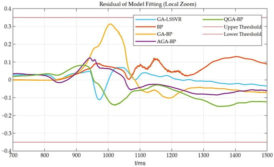
Figure 12.
Fault test detection (Figure 9) local amplification (700–1500).
From the perspective of stability consistency, the BP fault detection model fluctuated greatly in the stable stage, while the GA-BP fault detection model fluctuated greatly from the starting stage to the stable stage. In general, the GA-LSSVR, AGA-BP, and QGA-BP fault detection models performed well and were not prone to false alarm.
In summary, the five fault detection models of BP, GA-BP, AGA-BP, QGA-BP, and GA-LSSVR could realize the effective identification of the normal working state of this type of hydrogen and oxygen rocket engine and carry out effective real-time fault detection; they all met the real-time requirements of fault detection of this type of engine. Among the five fault detection methods proposed, the AGA-BP, QGA-BP, GA-BP, and GA-LSSVR fault detection models had certain advantages in fault detection and early warning, and GA-LSSVR, AGA-BP, and QGA-BP fault detection models were more stable in fitting the engine state. The related methods can be used for fault detection on the engine arrow and have certain engineering application value.
4.4. Design of an Integrated Intelligent Fault Detection Model
Combining various fault detection methods organically for engine fault detection can synthesize the advantages of different fault detection methods and improve the accuracy and robustness of the whole fault detection system. In the example of the fault detection system proposed in this paper, combined with specific engineering applications, a comprehensive fault detection method as shown in Figure 13 is adopted.
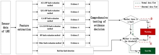
Figure 13.
Flow chart of comprehensive fault detection of a liquid rocket engine.
The specific method is as follows: Firstly, liquid rocket engine sensor data are extracted, and feature processing is carried out and then divided into two directions. The red line threshold fault detection method is taken as the fault detection method, that is, once the fault is detected by the red line threshold detection method, no matter whether the fault is detected by other fault detection methods, it is regarded as an engine fault at the current time, and the system will issue an early warning (see dotted line 1 in Figure 13). For other fault detection methods, such as the AGA-BP, QGA-BP, and GA-LSSVR fault detection methods proposed in the previous section, the corresponding evidence body is obtained by detecting the engine state at the same time, and then the comprehensive fault detection principle is chosen according to the evidence (such as the minority is subordinate to the majority, or if more than two methods think that the current system failure is an alarm) for fault detection (see dotted line 2 in Figure 13). For a fault detection system to think that the engine works normally, it is necessary to meet the condition that the joint detection of multiple fault detection methods does not meet the evidence decision comprehensive fault detection principle, and red line threshold fault detection does not exceed the red line threshold at the same time.
The method above is the most commonly used in engineering applications of the red line fault detection threshold value method as a way to a veto. It is the maximum guarantee under the combination of the current detection methods and can timely detect an LRE’s fault early warning. On the one hand, it can increase the reliability of test results through a variety of test methods of detection at the same time. On the other hand, it can be combined with the related methods so as to detect faults in advance. It will avoid or reduce losses to the greatest extent and accumulate data for subsequent fault detection decision adjustment.
5. Conclusions
This paper focuses on a comparative study of real-time intelligent fault detection algorithms for a certain type of hydrogen and oxygen rocket engine and concentrates on a model test of real-time fault diagnosis algorithms based on five fault detection models, including BP, GA-BP, AGA-BP, QGA-BP, and GA-LSSVR. The performances of the algorithms were compared with the test data of a hydrogen–oxygen rocket engine. The intelligent fault detection algorithm could be comprehensively analyzed from three dimensions: running time, fault detection ability, and stability consistency of the algorithm. In the detection of fault test data, the sequence of a fault warning issued by the five fault detection models was AGA-BP, QGA-BP, GA-BP, GA-LSSVR, BP. On the whole, the output of the fault detection models of GA-LSSVR, AGA-BP, and QGA-BP was relatively stable, and the variation fluctuation was small. Comprehensive analysis shows that a single intelligent fault detection algorithm always has its own shortcomings, and it is necessary to design a hybrid intelligent algorithm model that comprehensively utilizes the advantages of different intelligent algorithms. Future research will focus on a hybrid intelligent real-time fault detection algorithm model for the whole working process of a liquid rocket engine. It provides a reliable solution for the engineering application of real-time fault detection of a liquid rocket engine.
Author Contributions
Conceptualization, H.Y., P.H., L.D. and T.W.; methodology, T.W. and P.H.; software, H.Y.; validation, L.D. and P.H.; formal analysis, L.D. and P.H.; investigation, H.Y., P.H. and T.W.; resources, T.W.; data curation, H.Y., P.H. and Y.T.; writing—original draft preparation, P.H.; writing—review and editing, P.H. and T.W.; visualization, H.Y., P.H. and D.Z.; supervision, T.W.; project administration, T.W.; funding acquisition, T.W. All authors have read and agreed to the published version of the manuscript.
Funding
This research received no external funding.
Institutional Review Board Statement
Not applicable.
Informed Consent Statement
Not applicable.
Data Availability Statement
The data is not publicly available.
Conflicts of Interest
The authors declare no conflict of interest.
References
- Wu, J.; Cheng, Y.; Yang, S. Health Monitoring of Liquid Rocket Engine; Science Press: Beijing, China, 2021; pp. 1–46. [Google Scholar]
- Huang, M.; Xing, B. Fault Diagnosis of Liquid Rocket Engine based on Neural Network; National Defense Science and Technology University Press: Changsha, China, 2015. [Google Scholar]
- Dhital, D.; Lee, J.R.; Farrar, C.; Mascarenas, D. A review of flaws and damage in space launch vehicles: Motors and engines. J. Intell. Mater. Syst. Struct. 2013, 25, 524–540. [Google Scholar] [CrossRef]
- Li, X.; Shang, T.; Le, S.; Wang, C. Control Technology of New Generation Large Launch Vehicle Long March 5. Missiles Space Veh. 2021, 58–65. [Google Scholar] [CrossRef]
- Zhang, B.; Shen, D.; Zhang, Z.; Zhu, H.; Ma, Y. The Intelligent Flight Roadmap of Long March Launch Vehicle. Missiles Space Veh. 2021, 7–11. [Google Scholar]
- Cui, D. Research on Function Test and Fault Diagnosis Algorithm of Liquid Rocket Engine; Beijing University of Aeronautics and Astronautics: Beijing, China, 1995. [Google Scholar]
- Glenn, B.; Gu, M.; Yu, M.; Qiu, M. Automatic Adjustment of Liquid Rocket Motor; Zihang Publishing House: Beijing, China, 1995. [Google Scholar]
- Panossian, H.V.; Ewing, W.D. Real Time Failure Detection Algorithm for the Space Shuttle Main Engine. IEEE Control. Syst. 1997, 17, 16–23. [Google Scholar]
- Nemeth, E.; Division, R.; International, R. Health Management for Rocket Engines System; Rockwell International Corp.: Canoga Park, CA, USA, 1990. [Google Scholar]
- Bickford, R.; Malloy, D. Development of a Real-Time Turbine Engine Diagnostic System. In Proceedings of the 38th AIAA/ASME/SAE/ASEE Joint Propulsion Conference, Indianapolis, IN, USA, 7–10 July 2002. [Google Scholar]
- Fiorucci, T.; Lakin, D., II; Reynolds, T. Advanced Engine Health Management Applications of the SSME Real-Time Vibration Monitoring System. In Proceedings of the 36th AIAA/ASME/SAE/ASEE Joint Propulsion Conference and Exhibit, Huntsville, AL, USA, 17–19 July 2000. [Google Scholar]
- Hawman, M.W. Health Monitoring System for the SSME—Program Overview. In Proceedings of the 26th Joint Propulsion Conference, Orlando, FL, USA, 16–18 July 1990. [Google Scholar]
- Li, C.; Lu, K.; Shang, T. Intelligent Control of Launch Vehicle; China Astronautic Publishing House: Beijing, China, 2020; p. 144. [Google Scholar]
- Wu, J. Liquid-propellant Rocket Engines Health-monitoring—A Survey. Acta Astronaut. 2005, 56, 347–356. [Google Scholar] [CrossRef]
- Lv, H.; Chen, J.; Wang, J.; Yuan, J.; Liu, Z. A Supervised Framework for Recognition of Liquid Rocket Engine Health State Under Steady-State Process Without Fault Samples. IEEE Trans. Instrum. Meas. 2021, 70, 3518610. [Google Scholar] [CrossRef]
- Wu, J.; Zhu, X.; Cheng, Y.; Cui, M. Research Progress of Intelligent Health Monitoring Technology for Liquid-Propellant Rocket Engines. J. Propuls. Technol. 2021, 1–13. [Google Scholar]
- Wang, T.; Ding, L.; Yu, H. Research and Development of Fault Diagnosis Methods for Liquid Rocket Engines. Aerospace 2022, 9, 481. [Google Scholar] [CrossRef]
- Ali, M.; Gupta, U. An Expert System for Fault Diagnosis in a Space Shuttle Main Engine. In Proceedings of the 26th Joint Propulsion Conference, Orlando, FL, USA, 16–18 July 1990. [Google Scholar]
- Gupta, U.K.; Ali, M. LEADER—An Integrated Engine Behavior and Design Analyses Based Real-time Fault Diagnostic Expert System for Space Shuttle Main Engine (SSME); Association for Computing Machinery: New York, NY, USA, 1989. [Google Scholar]
- Flora, J.J.; Auxillia, D.J. Sensor Failure Management in Liquid Rocket Engine using Artificial Neural Network. J. Sci. Ind. Res. 2020, 79, 1024–1027. [Google Scholar]
- Park, S.; Ahn, J. Deep Neural Network Approach for Fault Detection and Diagnosis during Startup Transient of Liquid-propellant Rocket Engine. Acta Astronaut. 2020, 177, 714–730. [Google Scholar]
- Zhu, X.; Cheng, Y.; Wu, J.; Hu, R.; Cui, X. Steady-State Process Fault Detection for Liquid Rocket Engines Based on Convolutional Auto-Encoder and One-Class Support Vector Machine. IEEE Access 2020, 8, 3144–3158. [Google Scholar] [CrossRef]
- Yu, H.; Wang, T. A Method for Real-Time Fault Detection of Liquid Rocket Engine Based on Adaptive Genetic Algorithm Optimizing Back Propagation Neural Network. Sensors 2021, 21, 5026. [Google Scholar] [CrossRef] [PubMed]
- Yu, H.; Wang, T.; Tang, Y. A Method Using Quantum Genetic Algorithm optimized BP Neural Network of Real-time Fault Detection for the Liquid Rocket Engine. In Proceedings of the 2021 Global Reliability and Prognostics and Health Management (PHM-Nanjing), Nanjing, China, 15–17 October 2021; pp. 1–6. [Google Scholar]
- Huang, P.; Yu, H.; Wang, T. A Study Using Optimized LSSVR for Real-Time Fault Detection of Liquid Rocket Engine. Processes 2022, 10, 1643–1658. [Google Scholar] [CrossRef]
- Li, D.; Wang, J.; Chen, S. Key Technology Analysis of CZ-5 Launch Vehicle Propulsion Systme. J. Propuls. Technol. 2021, 42, 1441–1448. [Google Scholar]
- Huang, Q. Study on the Techniques of Fault Detection and Diagnosis for High Pressure Staged Combustion LOX/Kerosene Rocket Engine. Ph.D. Thesis, National University of Defense Technology, Changsha, China, 2012. [Google Scholar]
- Hu, L.; Hu, N.; Zhang, X.; Gu, F.; Gao, M. Novelty Detection Methods for Online Health Monitoring and Post Data Analysis of Turbopumps. J. Mech. Sci. Technol. 2013, 27, 1933–1942. [Google Scholar] [CrossRef][Green Version]
- Iannetti, A.; Marzat, J.; Lahanier, H.P.; Ordonneau, G. Automatic Tuning Strategies for Model-based Diagnosis Methods Applied to a Rocket Engine Demonstrator. In Proceedings of the PHM Society European Conference, Bilbao, Spain, 5–8 July 2016. [Google Scholar]
- Li, Y. Study on Key Techniques of Fault Detection and Diagnosis for New Generation Large-Scale Liquid-propellant Rocket Engines. Ph.D. Thesis, National University of Defense Technology, Changsha, China, 2014. [Google Scholar]
- Nie, Y. Investigation on Fault Prediction Methods Based on Process Neural Network For Liquid-Propellant Rocket Engines. Ph.D. Thesis, National University of Defense Technology, Changsha, China, 2017. [Google Scholar]
Publisher’s Note: MDPI stays neutral with regard to jurisdictional claims in published maps and institutional affiliations. |
© 2022 by the authors. Licensee MDPI, Basel, Switzerland. This article is an open access article distributed under the terms and conditions of the Creative Commons Attribution (CC BY) license (https://creativecommons.org/licenses/by/4.0/).