Abstract
In this work, we propose a systematic procedure to design a fuzzy logic controller (FLC) to control the lateral motion of powered parachute (PPC) flying vehicles. The design process does not require knowing the details of vehicle dynamics. Moreover, the physical constraints of the system, such as the maximum error of the yaw angle and the maximum allowed steering angle, are naturally included in the designed controller. The effectiveness of the proposed controller was assessed using the nonlinear six degrees of freedom (6DOF) mathematical model of the PPC. The genetic algorithm (GA) optimization technique was used to optimize the distribution of the fuzzy membership functions in order to improve the performance of the suggested controller. The robustness of the proposed controller was evaluated by changing the values of the parafoil aerodynamic coefficients and the initial flight conditions.
1. Introduction
A powered parachute (PPC) is a unique aircraft made up of a frame, a ram air parachute (parafoil), and a propeller that is driven by a piston or electric motor; see Figure 1. In the PPC, the thrust from its propeller causes the PPC to move forward, which enables its parachute to generate lift. To make turns, the PPC is controlled by directing the parachute right or left. Adjusting the engine power allows a PPC vehicle to ascend and descend [1].
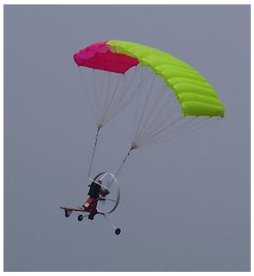
Figure 1.
Powered parachute flying vehicle.
The PPC vehicle has many advantages over the fixed-wing aircraft and the rotorcraft, including a low speed, low power consumption, high lifting capacity, light weight, compact size, safety, and survivability in case of engine failure [2]. These characteristics allow for the wide use of these vehicles in sports and fun activities. Autonomous PPC vehicles can also be used in photographing, spraying, cargo delivery, and military applications [1,3].
Longitudinal and lateral PPC control can be separately decoupled and treated. Longitudinal control is concerned with adjusting altitude [4,5], while the lateral control is concerned with tracking the horizontal trajectory [6,7,8]. Most controllers developed for the PPC vehicles have been based on the classical control techniques such as the proportional-integral-derivative (PID) controller [7] and frequency response [9] based on the linearized model at certain operating conditions. Model predictive control has also been proposed to control lateral PPC motion [8,10]. Two passivity-based control (PBC) algorithms were presented to stabilize a PPC vehicle such that it reaches its final desired position regardless of initial launch conditions [11]. Recently, vision-based control was suggested to control a PPC vehicle during landing [12]. The validation of these controllers has usually been conducted through numerical simulations.
One of the most active areas of fuzzy logic applications is the fuzzy logic control (FLC). Mamdani and his students began their research in 1965 by applying fuzzy control to a steam engine. Since then, there have been several studies and applications on various related processes, where it was demonstrated that an FLC is able to withstand changes in system parameters [13].
In this paper, an FLC is proposed to control the lateral motion of a PPC through waypoints. The rules are based on the Proportional-Integral-Derivative (PID) controller, and the distributions of the membership functions are tuned to minimize errors between the desired and actual yaw angles of the vehicle. Minimization was done with the genetic algorithm (GA) optimization technique. GA was chosen because it optimizes a performance index based solely on input/output correlations. As a result, only a basic understanding of the plant under inquiry is required. Furthermore, because derivative information is not required for the algorithm’s execution, many of the difficulties that gradient search approaches suffer from can be avoided [14].
2. Mathematical Modeling
A PPC can be modeled as a 6 or 9 degrees of freedom (DOF) system. It has been reported by many researchers that the 6DOF mathematical model for the PPC is accurate enough to simulate the performance of the vehicle for the purpose of controller design. In this 6DOF model, the relative motion between the parafoil and the fuselage that may occur during flight is neglected, and these two elements are treated as a single rigid body, as shown in Figure 2 [7].
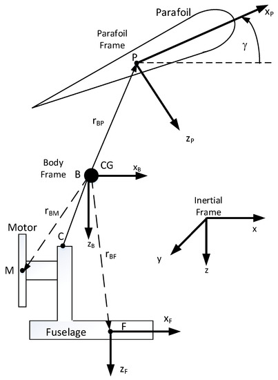
Figure 2.
PPC coordinate system.
To develop the mathematical model of the PPC, four frames were used: the earth frame, the body frame, the fuselage frame, and the parafoil frame. If we express the vector transpose by the superscript T, the position of the PPC center of gravity (CG) with respect to the earth frame is denoted by the vector , the velocity of the PPC CG with regard to the body frame is denoted by the vector , and the orientation in angular position of the body frame with respect to the earth frame is denoted by , which represent the roll, pitch, and yaw. The angular velocity vector of the PPC in the body frame can be written in terms of η as [15]:
The derivative of the inertial position can be written as:
where is the rotation matrix from the body frame to the earth inertial frame, which is given by:
where C and S are shorthand forms for cosine and sine, respectively.
The equations of the translational and rotational motions written in the body frame can be expressed as
where m is the whole mass of the PPC vehicle, g is the gravitational constant, and IB is the inertia matrix of the PPC written in the body frame. The subscripts F, M, and P refer to the fuselage, the motor, and the parafoil, respectively.
The force from the motor can be expressed as
where T is the thrust generated by the motor. The aerodynamic drag applied on the fuselage in the body frame can be expressed as
where ρ is the air density, AF is the fuselage projected area, and is the fuselage drag coefficient, which can be written as
The fuselage velocity VF can be determined as
Therefore, the angle of attack of the fuselage αF can be determined from
The aerodynamics force applied on the parafoil expressed in its frame can be written as
where and are the lift and drag coefficients of the parafoil, respectively, which can be written as
The angle of attack of the parafoil in its frame can be expressed as
The velocity of the parafoil in its frame can be determined from
where is the transformation matrix from the body frame to the parafoil frame, which can be expressed as
The aerodynamic moment applied on the vehicle is mainly generated by the parafoil, and it can be expressed in the body frame as
where c and b are the chord and span length of the parafoil, respectively.
The moment due to the parafoil steering angle , which is used to control the lateral motion, can be written as
For steady level flight, the following conditions should be satisfied:
3. Controller Design
Since the longitudinal and the lateral motions can be decoupled, the structure of the proposed controller is shown in Figure 3.

Figure 3.
Guidance and control loop.
To move the PPC through waypoints, the look-ahead guidance technique is used, as illustrated in Figure 4 [7,16].
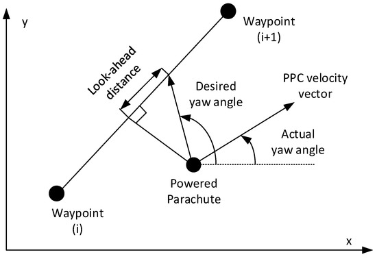
Figure 4.
Look-ahead guidance algorithm.
FLC Design
The structure of the proposed fuzzy controller for the lateral PPC motions is shown in Figure 5. The FLC has two inputs, the error and the error derivative, and the output is the parafoil steering angle.

Figure 5.
Structure of the PPC lateral FLC.
Selecting the number and distribution of membership functions (MFs) for the inputs and outputs comprises the first steps in the FLC design. Seven normalized membership functions with triangular shapes were studied in this paper; see Figure 6 [8]. To describe these functions, the location of the vertices of the triangles must be determined. Only two parameters (a1 and a2) are needed for each variable.
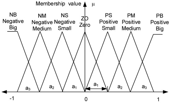
Figure 6.
The normalized membership functions for the FLC inputs and output.
To transform the normalized ranges of the MFs into physical operating ranges, the following scaling factors are used:
The proposed fuzzy inference system consists of 49 rules, which are shown in Table 1.

Table 1.
FLC rules.
To optimize the performance of the FLC, the membership functions parameters are determined such that the following objective function is minimized:
4. Simulation Results
The inertia and aerodynamics properties of the PPC model used in the simulation are listed in Table 2 for the mass and geometric properties and Table 3 for the aerodynamics coefficients [7].

Table 2.
PPC mass and geometry properties.

Table 3.
Aerodynamics properties.
The equilibrium points for the steady-state level flight as a function of the PPC forward velocity were determined and plotted, as shown in Figure 7. Stability was evaluated by determining the eigenvalues of the linearized models around these equilibrium points. Below u = 2.6 m/s, the equilibrium points could not be achieved, and the system became unstable above u = 7.3 m/s.
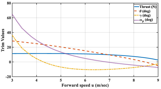
Figure 7.
Equilibrium operating points.
When the parafoil angle was 20 deg, the steady level flight could be achieved at To = 11.39 N, uo = 3.389 m/s, and θo = 27.2 deg. The effectiveness of the proposed lateral controller was demonstrated around this operating point using the 6DOF dynamical model.
For the simulation, the vehicle started at x = y = 0 with a heading angle ψ = 90 deg, the look-ahead distance was 5 m, and it was assumed that the vehicle would reach the waypoint within a circle of 2 m radius.
The maximum allowed steering angle of the parafoil angle was 60 deg, and the maximum allowed rate for the yaw angle was 0.05 rad/sec. With an equally spaced distribution of the fuzzy membership functions (i.e., ), the trajectory of the PPC moving through four waypoints was found to be shown as in Figure 8. The simulation indicated that the proposed FLC was able to allow the PPC to smoothly navigate through the waypoints. The time history of the error between the desired and actual yaw angles is shown in Figure 9. The error exponentially converged to zero in a short time. The steering angle for this maneuver is shown in Figure 10. The peaks were mainly due to the abrupt changes in the error derivative.
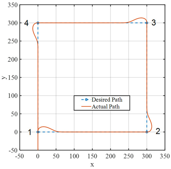
Figure 8.
PPC lateral path using the non-optimized FLC.
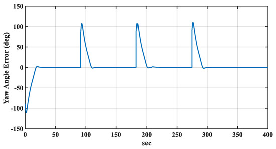
Figure 9.
Yaw angle error using the non-optimized FLC.
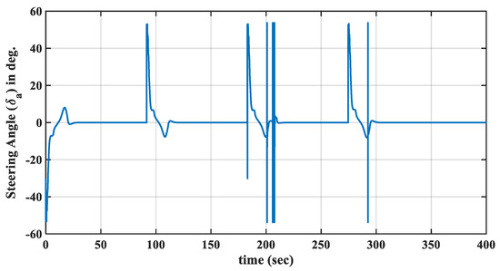
Figure 10.
Steering angle using the non-optimized FLC.
The time histories of the PPC inertial position and attitude angles are shown in Figure 11 and Figure 12, respectively. The altitude and pitch angles were used as constants to verify that the longitudinal and lateral motions were completely uncoupled.
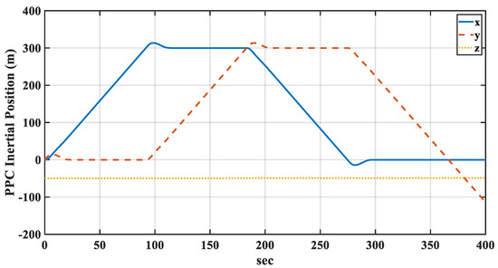
Figure 11.
Inertial position using the non-optimized FLC.
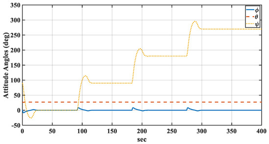
Figure 12.
Attitude angles using the non-optimized FLC.
4.1. Optimization
To improve the controller’s performance, GA was used to tune the MF distributions according to the algorithm shown in Figure 13. The GA parameters were set to 20 for the population size, 0.7 for the crossover rate, and 0.01 for the mutation rate. In this algorithm, the individuals that generate the offspring who join the next generation are chosen using linear ranking with the roulette wheel approach; when the objectives function has not improved in the last 30 generations, the algorithm ends [14,17].

Figure 13.
GA algorithm flow chart.
The evolutionary history of the GA is shown in Figure 14. The algorithm convergences and the best MF distributions are shown in Figure 15.
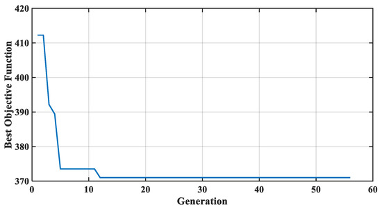
Figure 14.
GA evolution.
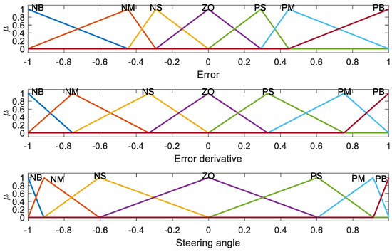
Figure 15.
Optimized distribution of MFs.
A comparison between the performance of the optimized and non-optimized FLCs is shown in Figure 16. It can be observed that the overshoot and the settling time slightly decreased with the use of the optimized FLC, which means that the FLC with an equally spaced MF distribution had a good performance.
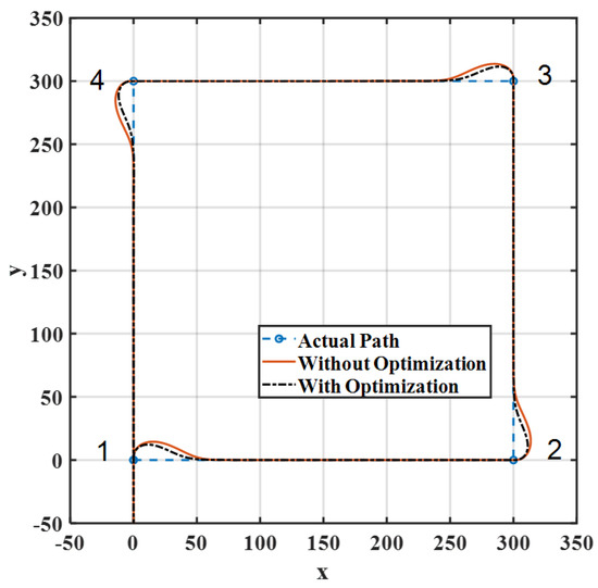
Figure 16.
Lateral path using the optimized FLC.
4.2. Robustness
To study the robustness of the proposed FLC, the aerodynamics properties of the parafoil that are related to the lateral motion were changed and the simulations were repeated. Increasing these coefficients by doubling their values improved the effectiveness of the parafoil in controlling the lateral movement, while decreasing these coefficients to half of their nominal values slightly degraded the performance of the system, as shown in Figure 17. In both cases, the proposed FLC performed well, and we observed small increases in the overshoot and settling time in the second case when the aerodynamic coefficients were decreased.
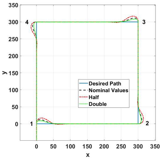
Figure 17.
Effect of changing the aerodynamics coefficients.
Figure 18 shows the performance of the designed controller with different initial conditions of the flight direction. It is shown that the controller was able to steer the vehicle to its desired direction, even it was initially flying in the opposite direction.
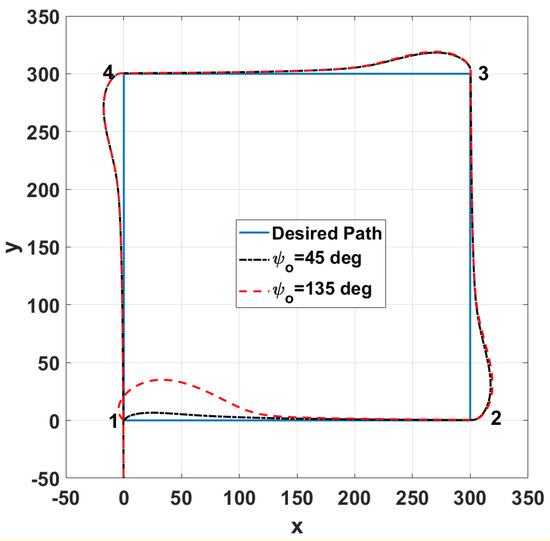
Figure 18.
Effect of changing the initial flight direction.
5. Conclusions
In this paper, a mathematical model of a PPC vehicle is presented and the trim values of this vehicle at a steady level flight are determined. An FLC is proposed to control the lateral motion of the PPC vehicle, and a GA was used to improve the performance of the proposed controller. Simulations with a nonlinear 6DOF system indicated the effectiveness of the proposed controller and its robustness in the face of different initial flight conditions and changes in the vehicle aerodynamics coefficients. The physical constraints of the vehicle, such as the maximum allowed yaw angle and its derivative, as well as the maximum available control action that is represented by the parafoil steering angle, are considered in the designed FLC controller.
Funding
This research received no external funding.
Acknowledgments
The researcher would like to thank the Deanship of Scientific Research, Qassim University for funding the publication of this project.
Conflicts of Interest
The author declares no conflict of interest.
References
- Bian, Y.; Jiang, T.; He, W. On the Development of Autonomous Powered Parachute. In Proceedings of the 2007 8th International Conference on Electronic Measurement and Instruments, Xian, China, 16–18 August 2007; pp. 4-387–4-392. [Google Scholar]
- Chambers, J.R. Longitudinal Dynamic Modeling and Control of Powered Parachute Aircraft. Master’s Thesis, Rochester Institute of Technology, Rochester, NY, USA, 2007. [Google Scholar]
- Devalla, V.; Prakash, O. Developments in unmanned powered parachute aerial vehicle: A review. IEEE Aerosp. Electron. Syst. Mag. 2014, 29, 6–20. [Google Scholar] [CrossRef]
- Aoustin, Y.; Martynenko, Y. Control Algorithms of the Longitude Motion of the Powered Paraglider. In Proceedings of the Proceedings the ASME 2012 11th Biennial Conference on Engineering Systems Design and Analysis, Nantes, France, 2–4 July 2012; pp. 1–6. [Google Scholar]
- Zaitsev, P.V.; Formalskii, A.M. Autonomous Longitudinal Motion of a Paraglider. Mathematical simulation, synthesis of control. J. Comput. Syst. Sci. Int. 2008, 47, 786–794. [Google Scholar] [CrossRef]
- Qu, S.T. Unmanned Powered Paraglider Flight Path Control Based on PID Neutral Network. Mater. Sci. Eng. 2019, 470, 012008. [Google Scholar] [CrossRef]
- Umenberger, J.; Goktogan, A.H. Guidance, Navigation and Control of a Small-Scale Paramotor. In Proceedings of the Australasian Conference on Robotics and Automation, ACRA, Wellington, New Zealand, 3–5 December 2012. [Google Scholar]
- Rademacher, B.J.; Lu, P.; Strahan, A.L.; Cerimele, C.J. In-Flight Trajectory Planning and Guidance for Autonomous Parafoils. J. Guid. Control. Dyn. 2009, 32, 1697–1712. [Google Scholar] [CrossRef] [Green Version]
- Kumar, P.; Sonkar, S.; Ghosh, A.K.; Philip, D. Dynamic Waypoint Navigation and Control of Light Weight Powered Paraglider. In Proceedings of the 2020 IEEE Aerospace Conference, Big Sky, MT, USA, 7–14 March 2020; pp. 1–8. [Google Scholar]
- Habib, W.; Elsabbagh, R.; El-Badawy, A. Optimal Dubins Path Generation, System Identification and Control of a Paramotor. In Proceedings of the 2019 IEEE International Conference on Vehicular Electronics and Safety (ICVES), Cairo, Egypt, 4–6 September 2019; pp. 1–6. [Google Scholar]
- García-Beltrán, C.; Miranda-Araujo, E.; Guerrero-Sanchez, M.; Valencia-Palomo, G.; Hernández-González, O.; Gómez-Peñate, S. Passivity-Based Control Laws for an Unmanned Powered Parachute Aircraft. Asian J. Control 2021, 23, 287–296. [Google Scholar] [CrossRef]
- Zhang, M.; Hu, W.; Ji, S.; Song, Q.; Gong, P.; Kong, L. Vision-Assisted Landing Method for Unmanned Powered Parachute Vehicle Based on Lightweight Neural Network. IEEE Access 2021, 9, 130981–130989. [Google Scholar] [CrossRef]
- Driankov, D.; Hellendoorn, H.; Reinfrank, M. An Introduction to Fuzzy Control; Springer: Berlin, Germany; London, UK, 2011. [Google Scholar]
- Goldberg, D.E. Genetic Algorithms in Search, Optimization, and Machine Learning; Addison-Wesley: Boston, MA, USA, 2012. [Google Scholar]
- Zipfel, P.H.; Werner, S. Modeling and Simulation of Aerospace Vehicle Dynamics; American Institute of Aeronautics and Astronautics: Reston, VA, USA, 2014. [Google Scholar]
- Elkaim, G.H.; Lie, F.A.P.; Gebre-Egziabher, D. Principles of Guidance, Navigation, and Control of UAVs. In Handbook of Unmanned Aerial Vehicles; Valavanis, K.P., Vachtsevanos, G.J., Eds.; Springer: Dordrecht, The Netherlands, 2015; pp. 347–380. [Google Scholar]
- Omar, H.M. Developing Integrated Fuzzy Guidance Law for Aerodynamic Homing Missiles By Genetic Algorithm. In Proceedings of the IEEE Congress on Evolutionary Computation, Daejeon, Korea, 15–18 December 2009; pp. 1019–1024. [Google Scholar]
Publisher’s Note: MDPI stays neutral with regard to jurisdictional claims in published maps and institutional affiliations. |
© 2021 by the author. Licensee MDPI, Basel, Switzerland. This article is an open access article distributed under the terms and conditions of the Creative Commons Attribution (CC BY) license (https://creativecommons.org/licenses/by/4.0/).