Abstract
An unsteady tightly-coupled icing model is established in this paper to solve the numerical simulation problem of unsteady aircraft icing. The multi-media fluid of air and droplets is regarded as a single medium fluid with variable material properties. Taking the droplet concentration as the phase parameter and the droplet resistance coefficient as the interphase force, the mass concentration distribution of the droplet is obtained by solving the Cahn–Hilliard equation. Fick’s law is introduced to improve the Cahn–Hilliard equation to predict the droplet shadow zone. On this basis, the procedure of the unsteady numerical simulation method for aircraft icing is established, including grid generation, the dual-time-step method to realize the unsteady calculation of the air and droplet tightly-coupled mixed flow field, and the improved shallow water icing model. Finally, through the comparative analysis of numerical examples, the effectiveness of the new model in predicting the droplet impact characteristics and the droplet shadow zone are verified. Compared with other icing models, the ice shapes predicted by the unsteady tightly-coupled model were found to be the most consistent with the experiments. In the icing comparison conditions in this manuscript, the prediction accuracy of the ice thickness at the stagnation point of the leading edge was up to 35% higher than that of LEWICE.
1. Introduction
The aircraft icing problem has been one of the most important problems in flight safety [1]. This problem can destroy the aerodynamic shape [2] and increase the resistance of aircraft [3], which is an important hidden danger leading to flight safety accidents. Due to the low cost and high efficiency [4], the ice shape prediction model and its numerical simulation method have become important methods to research the aircraft icing problem.
At present, a number of mature icing numerical simulation codes have been developed and widely used in industry, such as LEWICE developed by NASA [5,6], FENSAP-ICE developed by NTI (Newmerical Technologies International) [7,8], TRAJICED developed by DRA [9], IGLOO2D and IGLOO3D developed by ONERA [10] and so on. Although the numerical simulation methods of these software programs are different, the main numerical process can be divided into four calculation modules, including grid generation, airflow field calculation, droplet trajectory calculation and ice accretion calculation. The numerical simulation methods of droplet trajectory are mainly divided into Lagrangian method and Eulerian method.
The Lagrangian method takes a single droplet as the research object. By tracking its motion trajectory in the flow field, it can judge whether it collides with the surface of the airfoil, and then obtains the droplet collection coefficient. The Lagrangian method is often used to calculate the simple shape of the collection efficiency and is still widely used in LEWICE, ONERA, etc.
The Eulerian method, which has been applied to FENSAP-ICE, takes the continuous distribution of droplets in space as the research object. By solving the governing equation of the water phase, the mass and velocity distribution of droplets in the airflow field are calculated, and then the droplet collection coefficient of the icing surface is obtained. Both the Lagrangian method and Eulerian method ignore the influence of droplets on the airflow field; therefore, they can be considered as loosely-coupled models. The tightly-coupled model proposed in this paper regards the multi-media fluid composed of air and water droplets as a single fluid with variable material properties and focuses on the interaction between air and droplets.
The phase field method, also known as the diffuse interface method [11], has now become a powerful method to simulate multi-media fluid flow problems. It is commonly used in droplet coalescence, fragmentation, rise and change in shear flow, phase separation, contact line dynamics, surfactant adsorption interface dynamics and thermocapillary effects. Compared with other interface capturing methods, the phase field method has the following two advantages: first, it is easy to capture the interface using the numerical method even if the topology changes; secondly, the phase field method can be obtained with the energy-based variational method.
The results show that the phase field method is consistent with the law of energy dissipation, which makes it possible to design an efficient and energy stable numerical scheme. The phase-field method treats multi-phase fluids as one fluid with variable material properties [12]. Specifically, the phase-field method utilizes order parameters, such as the concentration or volume fraction of the fluids, to represent different fluid phases. The order parameter is typically evolved by the Cahn–Hilliard (C-H) equation, the Allen–Cahn equation or other types of dynamic equations to capture the motion of the fluid interface.
In the previous numerical simulation of aircraft icing, the small supercooled droplets with diameters ranging from 10 to 50 μm were regarded as rigid spheres, assuming that there is no deformation in the process of motion and always remains spherical, and their resistance coefficient can be obtained by the classical empirical formula of spherical resistance coefficient [13]. For supercooled large droplets with a diameter of more than 50 μm, Tan et al. [14] observed the process of large droplets impacting the airfoil and found that large droplets will deform or even eventually break when they are close to the airfoil. By adding the SLD deformation effect, they obtained a droplet collection coefficient closer to the experimental results.
Aircraft icing is an unsteady process. At every tiny time step, the growth of the ice layer at the leading edge of the airfoil will change its aerodynamic characteristics, which will affect the air flow field and droplet trajectory and eventually lead to the change of the ice shape [15]. In the current icing calculation methods, this is regarded as a steady-state or quasi steady-state problem and solved by the single-time-step method or multi-time-step method.
The multi-time-step method is introduced into the LEWICE, which can be divided into two categories: the first method [16,17,18] divides the total icing time into several time steps, and calculates the airflow field, droplet trajectory and ice growth in each time step. The specific process is shown in Figure 1a. However, because each time step is a complete and independent freezing process, the calculation consumes a great deal of time. In the second method [19,20], the airflow and droplet trajectory are only calculated at the initial time.
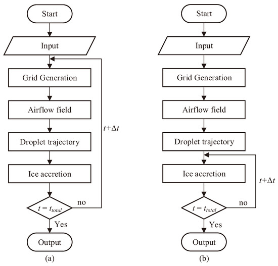
Figure 1.
Framework for the quasi-steady icing simulation.
The ice growth process is divided into multi-time steps, and each time step is a complete and independent single-time-step ice growth calculation, which is shown in Figure 1b. While the second method uses an unsteady method to improve the ice accretion model, this method is only suitable for low to moderate ice thicknesses or simple flow in the time step.
Reid et al. [7] developed an unsteady method for numerical simulation of in-flight electrothermal anti-icing or de-icing, using the conjugate heat transfer technique. In this numerical method, both the flow field and the droplet trajectory are solved in the steady state, and only the calculation method of icing and melting is unsteady. Zhang [21] and Ansell [22] successively developed a numerical simulation method of unsteady air flow field to characterize the sources of unsteadiness in iced airfoil aerodynamics.
On the basis of the Myers model [23], Gori [24] established a new model for ice accretion under rime and glaze conditions, which includes an unsteady description of the heat diffusion problem within the ice layer. Based on the numerical solution of the unsteady Stefan problem, Liu [25] established a three-dimensional aircraft icing model, which regards the heat conduction in the ice layer as an unsteady process. Xiao [26] used wall-modeled large-eddy simulation to investigate the unsteady flow characteristics for a 30P30N three-element iced airfoil.
The above unsteady studies of aircraft icing numerical simulation have thus far focused on the unsteady research of airflow field and the unsteady heat transfer of ice accretion model. However, these methods ignore that the aircraft icing is an unsteady process. Zhu [27] proposed an adaptive Cartesian method combined with the ghost cell method for the aircraft unsteady icing problem. However, this numerical method calculates the airflow field by solving Eulerian equations and then uses the Lagrangian method to obtain the droplet trajectories, and the solution of the droplet trajectories is still steady.
In view of this situation, in this paper, we propose a numerical simulation method of the unsteady tightly-coupled icing process. In this method, the multiphase flow of air and droplets are regarded as a single fluid with variable material properties. The mass concentration of droplets is selected as the phase parameter, and Fick’s law is introduced to improve the Cahn–Hilliard equation to predict the droplet shadow zone. At the same time, the dual-time-step method is introduced to calculate the unsteady multiphase flow. The shallow water icing model is also improved to be suitable for unsteady calculation. The flow chart of unsteady icing calculation is shown in Figure 2.
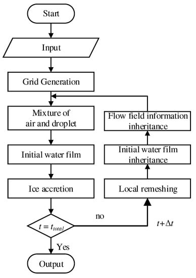
Figure 2.
Framework for the unsteady icing simulation.
The rest of the paper is organized as follows. In Section 2, the unsteady numerical method of aircraft icing is established, including grid generation, the calculation of air and water droplet tightly-coupled mixed flow field and the improved shallow water icing model. In Section 3, the correctness of the droplet collection coefficient calculated by the tight coupling model is verified. The accuracy of the new model in predicting the droplet shadow zone is presented in Section 4. In Section 5, the ice shapes are provided by the unsteady icing model under a series of icing conditions and compared with the experimental ice shapes and those provided by LEWICE. Finally, the main conclusions of the present work are provided in Section 6.
2. Materials and Methods
2.1. Grid Generation
In order to improve the computational efficiency, the grid partition method is introduced to divide the whole computational domain into several sub regions for grid generation, and the two-dimensional airfoil structure mesh is generated by solving the two-dimensional Poisson equations [28].
For two-dimensional airfoil icing, the icing mainly occurs at the leading edge of the airfoil, and the shape of other parts of the airfoil does not change; therefore, the corresponding mesh does not need to be updated and reconstructed. Thus, as shown in Figure 3, the whole calculation area is divided into the sectorial domain and non sectorial domain. The sectorial domain is the area where icing occurs, and its grid needs to be adjusted continuously with the advance of icing time, while the non sectorial domain only needs to be generated once at the initial time. The computational grid is shown in Figure 4.
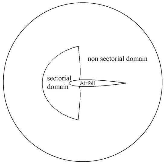
Figure 3.
Region division of the computational grid.
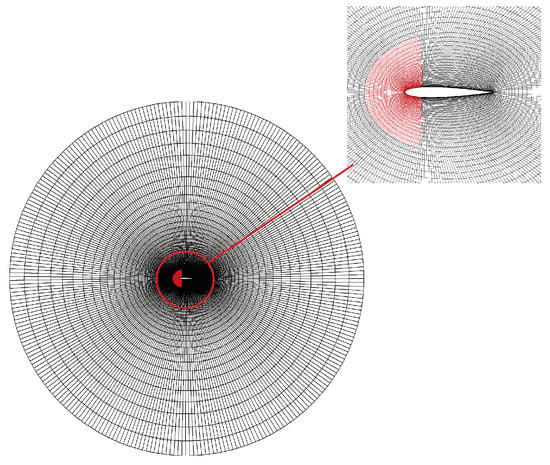
Figure 4.
The computational grid. The red grid is the sectorial domain.
In addition, according to our research, when the ice shape change in each physical time step is small enough, the mixed flow variables of air and droplets in the previous time step can be directly transferred to the new mesh without any correction by mesh velocity.
2.2. Tightly-Coupled Mixed Flow Field of Air and Droplets
In order to research the unsteady icing problem, the phase-field method is used to solve the tightly-coupled mixed flow field of air and droplets. In the control volume , the mass concentration of supercooled droplet is defined as the phase variable:
Then, the average density of the gas–liquid multiphase flow is defined by harmonic interpolation:
The viscosity coefficient and thermal conductivity k of multiphase flow are also calculated by harmonic interpolation:
where and are, respectively, the viscosity coefficients of water and air, and are, respectively, the thermal conductivities of water and air.
For any calculation unit, assuming that the two fluids move at different velocities , the mass conservation equation of each fluid is expressed as follows:
where is the mass flow rate in the calculation unit, including the mass flow caused by convection and the mass flow caused by diffusion, that is , and is the diffusion flow rate of fluid i. Two kinds of fluids are characterized by i = 0 and 1, respectively. When i = 0, it means fluid 0, and when i = 1, it means fluid 1.
According to Equation (4), the mass conservation equation of multiphase flow can be obtained by:
where is the velocity of air , and is the velocity of droplet. The average density and the average velocity in the calculation unit are defined as follows:
Taking Equation (6) into Equation (5), the mass conservation equation of multiphase flow can be obtained as follows:
The diffusion mass flow rates of the two fluids should be equal in absolute value and opposite in direction, .
To sum up, the calculation formula of the mass equation of multiphase flow can be described as:
In the following derivation, the multiphase flow is regarded as a single fluid moving at velocity .
The Cahn–Hilliard (C-H) equation and free energy density formula are as follows:
where is the nonnegative permeability of the phase field. The free energy density can be obtained by:
For the simple airfoil icing problem, this effect can be ignored; however, for the complex aircraft icing problem, the droplet impact characteristics and droplet collection coefficient of the object surface near the trailing edge of the airfoil may be affected, resulting in numerical inaccuracy. Considering the diffusion effect caused by concentration differences, the range of the droplet shadow zone can be predicted more accurately. In order to take the diffusion effect of droplets into account, a macroscopic motion law is introduced to describe the phenomenon of matter diffusion, namely Fick’s law. According to the definition of Fick’s law, the phase equation of a water droplet can be written as follows:
where D is the diffusion coefficient.
In conclusion, the phase equation can be written as follows:
The force exerted by air on droplets is mainly composed of pressure difference resistance and friction resistance, and the portion of pressure versus resistance forces is different for different shaped objects. According to the literature, whether it is a spherical body or a disk-shaped object, the proportion of pressure difference resistance to the total resistance is more than 90%. Therefore, when we study the drag coefficient of water droplets, we typically only consider the pressure drop resistance and ignore the friction resistance. According to Newton’s third law, the force of water droplets on air is equal to that of air on droplets and directed to contrary parts as shown in Figure 5.
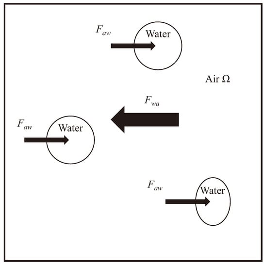
Figure 5.
The force diagram of droplets and air in the unit.
According to Newton’s third law of motion (force and acceleration), the force formula of a droplet on air can be written in the form [16]:
where, is the volume of the droplet, and K is the air–droplet interaction factor, which is specified in the form:
where the factor f is the drag function and defined differently for different exchange coefficient models. In this paper, according to the Schiller–Naumann model, the drag function is given as:
When the diameter of the droplet is small, the aerodynamic force of the droplet is smaller than the surface tension of the droplet. Therefore, it is generally considered that the droplet can remain spherical in the process of movement without deformation, and its drag coefficient can be obtained by the formula of the spherical resistance coefficient. However, when the diameter of the water droplet is large, the aerodynamic force of the droplet will exceed its surface tension and become the dominant factor in the process of movement, which makes it difficult to keep the droplet spherical and deform in the process of movement, , eventually leading to the change of aerodynamic force and motion state. Therefore, the deformation of large droplets can no longer be ignored.
Honsek [29] regarded the deformation of droplets as a spring system, and considered that the shape of droplets in the deformation process is between the rigid sphere and the disk, and the resistance coefficient between them can be obtained as:
where, is the drag coefficient of a spherical droplet and is the droplet drag coefficient of the equivalent disk. The eccentric action coefficient is written in the form:
is the dimensionless relative Weber number, which is used to characterize the ratio of the surface tension to inertial force of water droplets and is given as
where is the density of air, is the droplet diameter, and is the surface tension coefficient.
The calculation formulas of the drag coefficient of a spherical water drop and that of a water drop equivalent to a disc are given as a wide range function of the Reynolds number [30,31]:
is the relative Reynolds number of water droplets, and the calculation formula can be given as follows:
By inserting the force into the original calculation model of air flow and droplet [32], the improved continuity equation and energy equation can be obtained as follows:
In which t is the physical time step, and is the virtual time step. The intermediate variables of viscous stress and are expressed as follows:
At present, the most widely used unsteady calculation methods in computational fluid dynamics can be divided into two categories: the physical time iteration method and dual-time-step method [33]. When the physical time step iterative method is used to deal with unsteady flow problems, due to the limitation of stability conditions, the time step needs to be smaller, which results in a longer calculation time.
Faced with this issue, the dual-time-step method proposed by Jameson for unsteady calculation has incomparable advantages. In the dual-time-step method, the whole calculation process is divided into several physical time steps, and the virtual time step is adopted in each physical time step to convert the unsteady problem into the steady problem. At the same time, the local time step and residual smoothing method can be used to accelerate the convergence and improve the calculation efficiency.
The whole calculation process is divided into several physical time steps. Then, on the physical time step, the fully implicit form of the governing equation is as follows:
The second order backward difference scheme is used for the time term of Equation (23), and its expression is written as follows:
Here, we define a new residual value as follows:
where is the approximation of . By introducing the virtual time step , the implicit unsteady equation is transformed into the steady form of the virtual time:
In the iterative process of virtual time step, the fourth-order Runge–Kutta method is used to solve the problem explicitly. The virtual time step is limited by the stability condition, and its expression is as follows
The finite volume method based on the cell centered form is applied for the discretization in space. An improved Jameson center scheme is used to calculate the inviscid fluxes. In order to suppress the numerical oscillation, the artificial dissipation term is also introduced [34]. The S-A model is chosen for the turbulent model.
2.3. Ice Accretion Model
The shallow water icing model (SWIM) [35] is an improvement over the Messinger model. Its greatest advantage is the unsteady nature of the SWIM and the way it models the water film for more complex configurations compared with a simple 2D airfoil. Therefore, the SWIM is introduced into the icing calculation and needs to be improved to be used in unsteady model.
As shown in Figure 6, in the shallow water icing model, the water film flow is simplified as a Coutte flow under the action of air shear stress, and the velocity of water film can be approximately described in the form of a linear distribution:
where s is the arc direction of the surface, and y is the normal direction of the surface. Then, the average flow rate of the water film can be defined as:
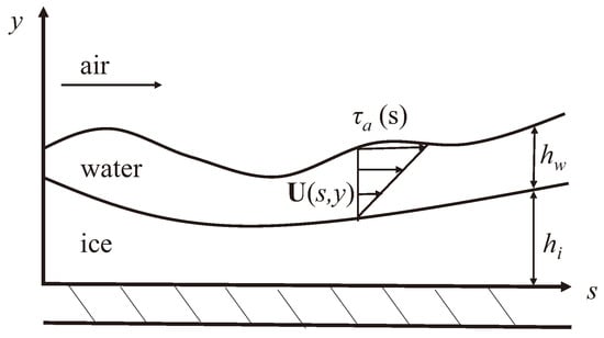
Figure 6.
Diagram of water film.
In which is the thickness of the water film, is the thickness of the ice layer, and is the shear stress of the air flow on the water film. The calculation formula of the mass conservation equation in the control volume is as follows:
In which is the mass balance of inflow and outflow in the control volume, and is the represents the increase of water film height with physical time. For the unsteady model used in this paper, it can be described as:
where is the water film height of the current physical time step. is the height of residual water calculated in the previous physical time step, and are respectively the inflow and outflow of liquid water in the control volume.
In Equation (20), is the water droplet collection rate. is the evaporation rate, which is obtained by analogy with the convection heat transfer term. is the freezing rate. The unknown terms are specified as follows [36]:
where is the droplet collection coefficient. is the convective heat transfer coefficient. is the specific heat capacity of air. is the Lewis criterion number, which is related to the , with a general value of 1. is the gas constant of the water vapor. and are, respectively, the saturated vapor pressures corresponding to the internal surface temperature , and . f is a dimensionless freezing parameter, which is used to characterize the ratio of frozen water to entering water in the control volume.
In which and are the latent heat of water and ice. is the specific heat capacity of water. is the velocity of the impinging droplets. is the the thermal conductivity of air. is the total temperature of the incoming stream, and is the total pressure of the incoming stream, which can be specified as follows:
where is the heat capacity ratio of air and is the inlet Mach number.
The energy conservation equation in the control volume can be written as follows:
where is the heat flux of heat conduction between the water film and the ice layer. is the energy density taken away by evaporation or sublimation on the surface of the water film. is the radiation heat flux of the water film. is the heat flux of heating. is the convective heat transfer density between the water film and the air flow. is the heat flux of pneumatic heating. is the heating heat flux converted from kinetic energy when water droplets impact. is the latent heat flux of liquid water freezing. The unknown terms are specified as follows:
In which is the temperature of the impinging droplets. is the boundary layer recovery temperature.
In icing simulations, the convective heat transfer process has a great influence on the ice shape and is the key to solving the convective heat transfer process. At present, most icing simulations use the boundary layer integral functions proposed by LEWICE, which consider the surface roughness and velocity variation to solve the convection heat transfer coefficient [37].
where is the thermal conductivity of air. is the kinematic viscosity of air. is the velocity of air at the outer boundary of the boundary layer. s is the surface distance. is a Prandtl number, which is approximated as a constant 0.9. and are, respectively, the Reynolds number at the rough surface and the critical Reynolds number. is the friction coefficient between the air flow and the wall surface. is a rough Stanton number, which can be obtained by
where is the roughness height, which can be obtained by Shin’s improved equivalent sand roughness height model [38].
The liquid water flow on the surface is considered in SWIM, and the water film flow velocity is related to the water film thickness. In order to ensure the operation of the calculation, it is necessary to assume that there is a very thin water film on the surface at the initial time. The traditional SWIM does not consider the real situation of the initial water film, and manually sets the initial water film thickness as a constant (for example, assuming that the initial water film thickness is m), and solves SWIM on this basis.
As the physical time step of the unsteady icing numerical simulation method used in this paper is small, it can be considered that at the initial time, the icing surface will form a water film and then freeze into ice, and the initial liquid water mass is the difference between the mass of the impact droplets and the amount of evaporation:
For quasi-steady icing calculations, due to the long physical time step, if the initial water film is simply used, it will lead to the problem that the initial water film is too thick and the water film flow velocity is too large, which will affect the calculation of icing shape. Therefore, for the quasi-steady icing calculation, the initial water film of each physical time step needs to be obtained before solving the SWIM, which is assumed in this paper that there is a short period of time at the initial time during which the surface liquid water does not freeze, and then the surface liquid water content distribution is obtained. However, for unsteady icing calculations, except that the initial water film of the first physical time step is obtained using the above method, the initial water film of each subsequent physical time step can be obtained by inheriting the calculation results of the previous physical step.
3. Verification of the Impact Characteristics
Before comparing the ice shapes, the accuracy of the tightly-coupled method to calculate the droplet collection coefficient should be verified. The summary of the icing aerodynamic database is shown in Table 1.

Table 1.
Icing conditions for the SSD (Supercooled Small Droplet)-case and SLD (Supercooled Large Droplet)-case.
Figure 7 shows the contour of droplet volume fraction around the airfoil. Due to the angle of attack, the impact range of droplets on the lower surface of the airfoil is larger than that on the upper surface. The reference results from experiment [39], FENSAP and the Lagrangian method are used for comparison with the result from the tightly-coupled method in the SSD case, which is shown in Figure 8.
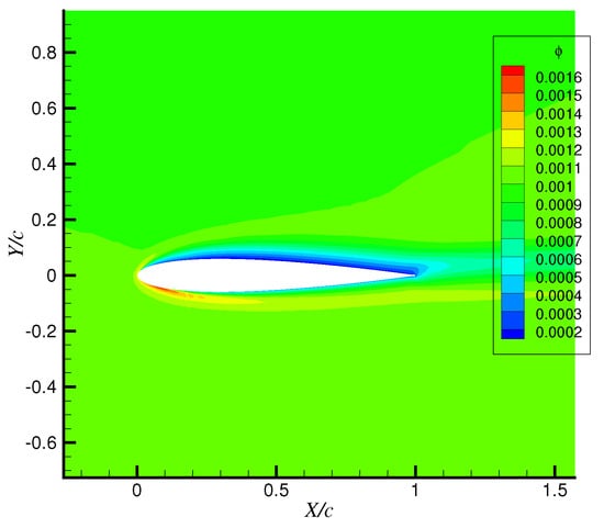
Figure 7.
Droplet volume fraction diagram.
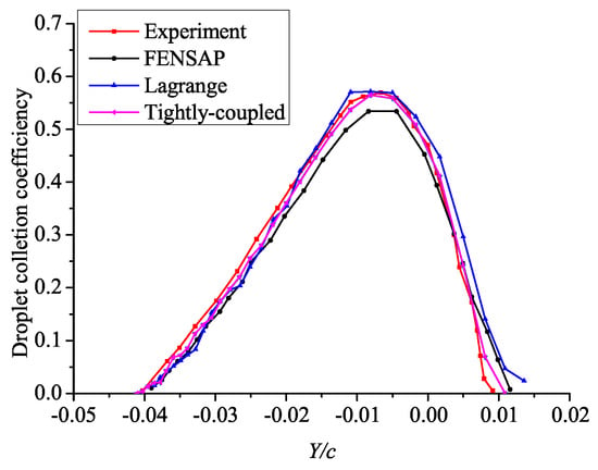
Figure 8.
Droplet collection coefficient of the SSD-case.
As can be seen from the figure, the results from the tightly-coupled method are essentially coincident with the experimental results, and are similar to those provided by the Eulerian method. The maximum droplet collection coefficient calculated by the tightly-coupled method and other methods are shown in Table 2. It can be seen from the figure that the maximum droplet collection coefficient predicted by the tightly-coupled model is the closest to the experimental value.

Table 2.
The maximum collection coefficient.
Figure 9 shows the comparison of the results provided by the icing codes and the experiment in the SLD case. In this case, the normal model indicates that the classical spherical resistance model is adopted without considering the dynamic mechanical effect of droplets, while the SLD model indicates that the droplet resistance coefficient model considering deformation [29] is adopted, and the crushing [40] and splashing [41] models are introduced.
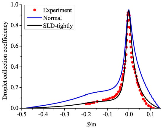
Figure 9.
Droplet collection coefficient of the SLD-case. The normal model is the Eulerian method without droplet deformation, breaking, splashing, bouncing and spreading.
According to the droplet diameter and droplet velocity, the broken droplet diameter and final droplet collection efficiency are modified by the crushing model and splashing model, respectively. It can be seen that the droplet collection coefficient from the SLD-tightly-coupled method agrees with the experimental results. In conclusion, the droplet collection efficiency predicted by the tightly-coupled model is in good agreement with the experimental results, which verifies the correctness of the model.
4. Droplet Shadow Zone
In order to study the influence of the droplet shadow zone, a cylinder with a diameter of 1 cm was selected as the research object: the air velocity = 40 m/s, the angle of attack AOA = 0°, the flight height h = 0 km, the ambient temperature T = 273.15 K, the liquid water content LWC = 1 g/m3, and the droplet diameter MVD = 40 μm. The calculation result and the experimental result of reference [42] are shown in Figure 10. It can be seen from the figure that the boundary of the sheltered area obtained by the numerical simulation is the same as the experimental results, which proves the accuracy of the tightly-coupled model in this paper in predicting the shadow zone of droplets, and also shows the correctness of the calculation results of water droplet trajectory.
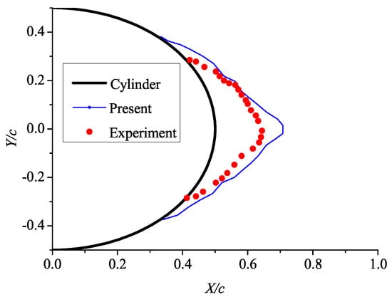
Figure 10.
Comparison of calculation result and experimental result in droplet shadow zone. The area surrounded by the red dot is the droplet shadow zone obtained from the experiment [42], and the area surrounded by the blue line is the droplet shadow zone predicted by the tightly-coupled model.
Then, the NACA0012 airfoil is selected as the research object, with chord length c = 1 m, incoming Mach number Ma = 0.382, angle of attack AOA = 6°, flight height h = 0 km, ambient temperature T = 300 K, liquid water content LWC = 1 g/m3 and water droplet diameter MVD = 20 μm. Figure 11 shows the droplet shadow zone calculated with the Eulerian method and the droplet trajectory obtained by the Lagrangian method. It can be seen from the figure that the two areas are essentially the same and extend downstream for too far, which is inconsistent with the actual situation in reference [42]. Therefore, both methods cannot accurately describe the location and scope of the droplet shadow zone. Figure 12 and Figure 13 show, respectively, the cloud image of droplet concentration and the droplet shadow zone calculated by the tightly-coupled model in this paper. The blue area is the droplet shadow zone, and the liquid water content in this area is 0, which is far less than the calculation results of the Eulerian method and Lagrangian method. This is due to the diffusion effect of the droplet flow field in the tail region of the airfoil, and the droplet shadow zone is greatly reduced compared with the former two methods. The results show that the droplet shadow zone can reach 10% behind the trailing edge of the airfoil.
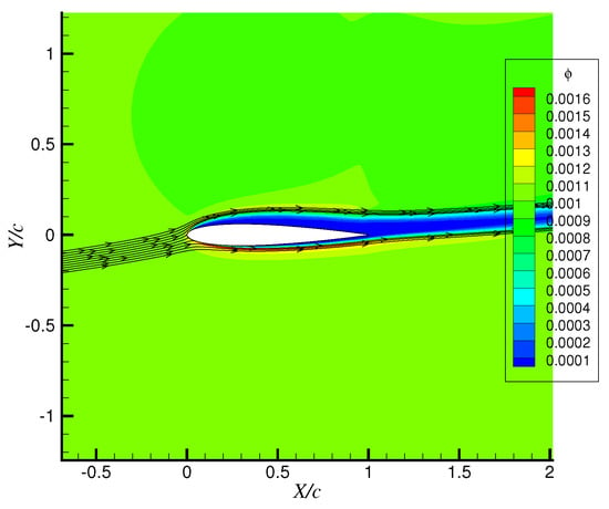
Figure 11.
Liquid water content calculated by the Eulerian model and droplet trajectory by the Lagrangian method.
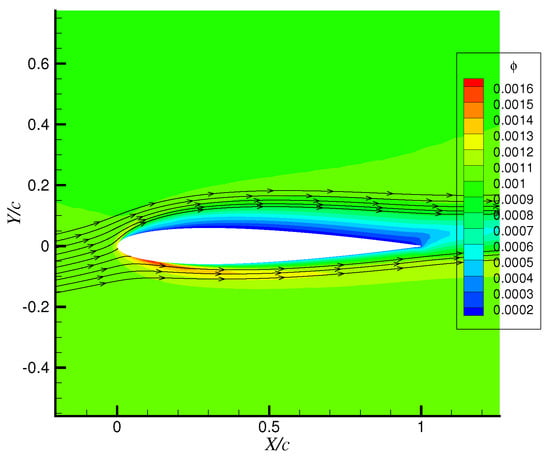
Figure 12.
Liquid water content calculated by the tightly-coupled method.
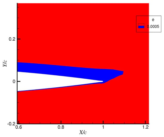
Figure 13.
Droplet shadow zone at the airfoil trailing edge. The blue area is the droplet shadow zone where the liquid water content is considered to be 0.
5. Verification of Ice Shape
In order to compare the experimental shapes and the shapes provided by different icing codes, a total of six ice shapes and the icing conditions were selected from the literature, which are listed in Table 3. For the purposes of comparison, the stagnation thickness and horn angle were chosen to be the ice shape characteristics, which were determined for the reference and prediction ice shapes.

Table 3.
Icing conditions for the SSD-case and SLD-case.
Through these characteristic values illustrated below in Figure 14, it is easy to calculate the deviations between the experimental shapes and the prediction shapes provided by different icing codes. At the same time, in order to verify the accuracy of the unsteady tightly-coupled model, the ice shapes calculated by the new model are compared with those calculated by the one-step LEWICE icing code based on the Messinger model.
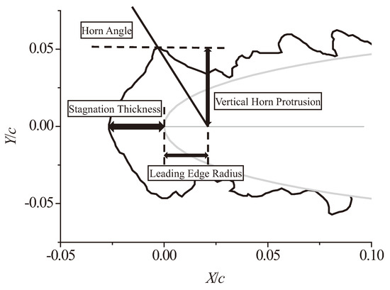
Figure 14.
Ice shape characterization metrics.
5.1. Ice Shape Predication for Unsteady Model and Quasi-Unsteady Model
Before verifying the unsteady tightly-coupled icing model, it is necessary to clarify the difference between the unsteady model and the quasi-steady model. The comparison of ice shapes in Case 6 shows that the smaller the physical time step is, the closer the ice shape is to the experimental result, as shown in Figure 15. The results in Table 4 show that the stagnation thickness is closer to the experimental results with the decrease of the physical time step.
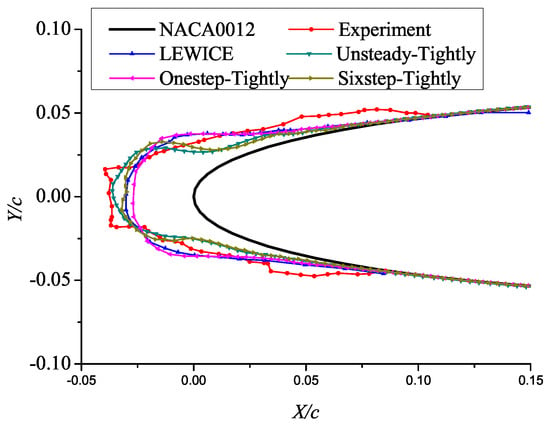
Figure 15.
Comparison of ice shapes.

Table 4.
Deviations of stagnation thickness.
For the quasi-steady model, because it is a complete and independent icing calculation process in each physical time step, the amount of calculation will increase with the decrease of physical time step. Therefore, for the sake of computational efficiency, the physical time step of the quasi-steady model is usually not defined as too small. The unsteady model can maintain the computational efficiency even though the time step is very small.
In this paper, the physical time step in the unsteady model was selected as 1 s. Except that the first time step is a complete steady icing calculation process, the remaining time steps only need to calculate 20 steps. When the physical time step is 1 s, the unsteady calculation process of Case 6 only takes 1 h, while the quasi-steady calculation process takes 12 h.
5.2. Verification Analysis of Unsteady Tightly-Coupled Model
The icing conditions calculated in this section are shown in Table 3, in which Case 1 to Case 4 focus on the icing of SSD, and Case 5 and Case 6 focus on the icing of SLD. Figure 16 show the comparison of ice shapes from the experiment, unsteady tightly-coupled model and LEWICE 3.0 under SSD icing conditions. Table 5 and Table 6 show, respectively, the deviation of stagnation thickness and horn angle provided by the unsteady tightly-coupled model LEWICE and the experiment.
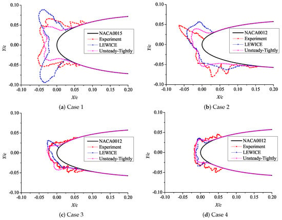
Figure 16.
Ice shapes of SSD cases.

Table 5.
Stagnation thickness of the SSD cases.

Table 6.
Horn angle of the SSD cases.
This set of data demonstrate that the stagnation thickness and horn angle from tightly-coupled model are closer to the experiment than those from LEWICE. Combined with the ice shape comparison results, the ice shape predicted by the tightly-coupled model is more similar to the experimental ice shape than LEWICE.
Figure 17 shows the comparison of ice shapes from the experiment, unsteady Eulerian method and LEWICE under SLD icing conditions. Figure 17a shows the comparison of numerical icing simulation under Case 5 meteorological conditions. In this icing condition, the ice shapes predicted by LEWICE form a concave angle at the leading edge of the airfoil.
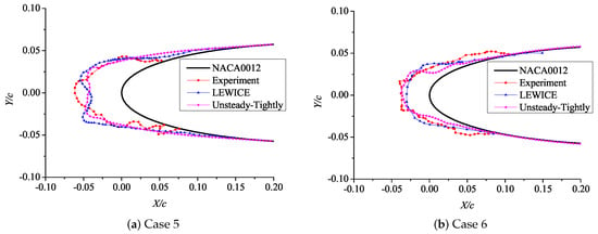
Figure 17.
Ice shapes of SLD cases.
The ice shape at the leading edge of the airfoil obtained by the numerical simulation of the unsteady tightly-coupled icing model can be considered to have no concave angle formation, and the result is closer to the experimental result. Figure 17a shows the comparison of numerical simulation of icing under Case 6. Under this icing condition, a convex angle is formed at the leading edge of the airfoil by the three methods.
Compared with the calculation results of the LEWICE 3.0 ice model, the convex angle formed by the unsteady tightly-coupled model is larger, and the ice thickness at the stagnation point is more consistent with the experimental result. As shown in Table 7, the deviation of stagnation thickness provided by the tightly-coupled model and the experiment is smaller than that by LEWICE. The ice shape predicted by the unsteady tightly-coupled model is closest to the experimental ice shape. In particular, in Case 5, only the unsteady tightly-coupled model can capture the ice shape characteristics.

Table 7.
Stagnation thickness of SLD cases.
In conclusion, from the comparison of ice shape characteristics, the calculation results of the tightly-coupled model demonstrated higher accuracy than those of LEWICE, and the deviations with the experimental results were smaller.
5.3. Ice Shape Predication for Tightly-Coupled Model and Loosely-Coupled Model
Aircraft icing is an unsteady process of two-way interaction between water and air. The influence of droplets on the air will increase with time, and thus the droplet collection coefficients calculated by the Eulerian model and tightly-coupled model are different, and the droplet collection coefficient has an important influence on the icing ice shape, which leads to the difference of the final calculated ice shape and the change of aerodynamic force. In this paper, the Eulerian model was chosen as a loosely-coupled model.
The unsteady Eulerian model and unsteady tightly-coupled model were used to predict the ice shapes in Case 1 and Case 5. The comparisons between the ice shapes calculated by the above two icing models and the ice shapes from experiment and predicted by LEWICE [45] are shown in Figure 18 and Figure 19. Figure 20 is an enlarged view of the leading edge ice shape. Under Case 1, the ambient temperature is −9.9 °C and the ice shape predicted by the unsteady loosely-coupled model is quite different from that predicted by LEWICE, which is closer to the experimental shape. Table 8 shows that the stagnation thickness provided by the unsteady tightly-coupled model is closest to the experiment.
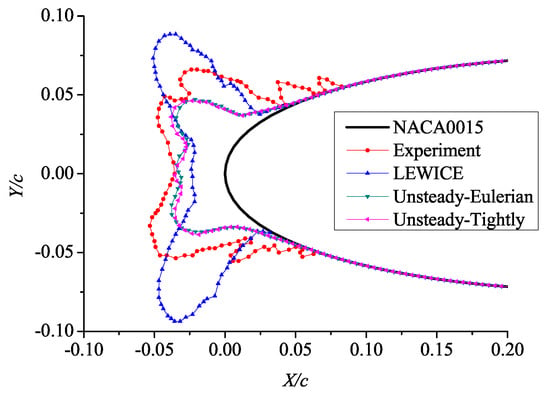
Figure 18.
Comparison of ice shapes under Case 1 (Temperature = −9.9 °C).
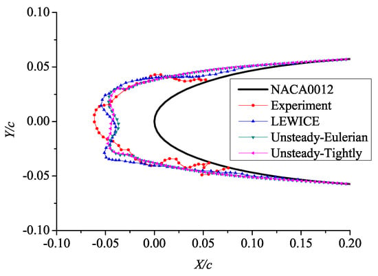
Figure 19.
Comparison of ice shapes under Case 5 (Temperature = −19.6 °C).
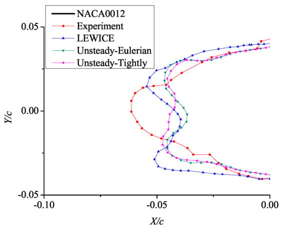
Figure 20.
Enlarged view of the comparison of ice shapes at the leading edge of an airfoil.

Table 8.
Stagnation thickness of Case1 and Case 5.
Under Case 5, the ambient temperature is −19.6 °C, the leading edge of the experimental ice shape is convex, but the ice shape predicted by the unsteady-Eulerian model forms a concave angle at the leading edge of the airfoil, just like the ice shape predicted by LEWICE. The ice shape calculated by the unsteady tightly-coupled icing model does not form a concave angle at the leading edge, which is closer to the experimental ice shape.
In addition, the ice shape predicted by the unsteady-Eulerian method is essentially consistent with that predicted by LEWICE. Table 8 shows that the stagnation thickness provided by unsteady tightly-coupled model is closer to the experiment than that predicted by the unsteady-Eulerian model and LEWICE.
In summary, when the temperature is low, the icing model has the smaller impact, and the tightly-coupled model has the larger impact. At high temperatures, SWIM has the larger impact, and the tightly-coupled model can further improve the accuracy on this basis.
The tightly-coupled model and the Eulerian model were used to calculate the droplet collection coefficient of Case 5. Figure 21 and Figure 22 show the calculation results at the initial time and t = 804 s, respectively. At the initial time, the results of the two models essentially coincide. With the increase of time, when t = 804 s, the difference between the two models is significant. Especially in the leading edge of the airfoil, the droplet collection coefficient calculated by the tightly-coupled model is significantly greater than that calculated by the Eulerian model.
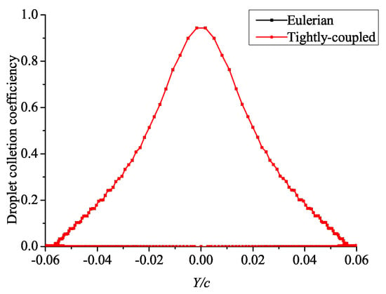
Figure 21.
Distribution of the droplet collection coefficient at the initial time.
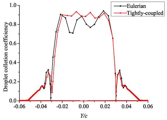
Figure 22.
Distribution of the droplet collection coefficient at t = 804 s.
6. Conclusions
In this paper, we proposed a numerical simulation method for unsteady tightly-coupled icing model. The air and droplets were regarded as a single fluid, and the unsteady calculation was realized by using the dual-time-step method. The shallow water icing model was improved to adapt to the unsteady ice settlement.
The droplet collection coefficients of NACA0012 airfoil under different icing conditions were calculated and analyzed using the tightly-coupled model. The results show that the tightly-coupled model could accurately predict the droplet collection coefficient, which was the most consistent with the experimental results compared with the Lagrangian method and FENSAP-ICE. At the same time, the tightly-coupled model could correctly predict the droplet shadow zone.
The ice shapes under different icing conditions, including SSD and SLD icing conditions, were predicted and analyzed. The results show that, with the decrease of the physical time step, the ice shape predicted by the unsteady model was closer to the experimental result, and the unsteady model maintained the computational efficiency compared with the quasi-steady model. As time increased, the cumulative effect of droplets on the airflow field gradually appeared, the difference between the results of the tightly-coupled model and the loosely-coupled model increased, and the results of the tightly-coupled model were more consistent with the experimental ice shapes. When the temperature was low, there was little difference between the loosely-coupled model and LEWICE in predicting ice shape, indicating that the influence of icing model was small and the tightly-coupled model had the larger impact. At high temperatures, SWIM had the larger impact, and the tightly-coupled model could further improve the accuracy on this basis.
Through comparative analysis of the numerical simulations and the experimental results, the ice shapes predicted by the unsteady tightly-coupled model were more consistent with the experimental ice shapes under different icing conditions. Compared with LEWICE, the unsteady tightly-coupled model had higher accuracy. For glaze ice, especially horn ice, where the existing icing methods, such as LEWICE, cannot accurately capture the ice shape characteristics, the unsteady tightly-coupled model could more accurately predict the ice shapes and successfully capture the ice shape characteristics.
Author Contributions
Conceptualization, H.D., C.Z. (Chengxiang Zhu), N.Z., C.Z. (Chunling Zhu) and Y.C.; methodology, H.D.; software, H.D.; validation, H.D.; formal analysis, H.D.; investigation, H.D.; resources, H.D.; data curation, H.D.; writing—original draft preparation, H.D.; writing—review and editing, H.D., C.Z. (Chengxiang Zhu), C.Z. (Chunling Zhu) and Y.C.; visualization, H.D.; supervision, C.Z. (Chunling Zhu); project administration, C.Z. (Chunling Zhu); funding acquisition, C.Z. (Chunling Zhu). All authors have read and agreed to the published version of the manuscript.
Funding
This research was funded by the National Natural Science Foundation of China (Grant No. 11832012), Research Fund of State Key Laboratory of Mechanics and Control of Mechanical Structures (Nanjing University of Aeronautics and astronautics) (Grant No. MCMS-I-0120G01), Research Fund of Key Laboratory of Aircraft Environment Control and Life Support, MIIT (Nanjing University of Aeronautics and Astronautics) (Grant No. KLAECLS-E-202003) and Open Fund of Key Laboratory of Icing and Anti/De-icing (Grant No. IADL20190302).
Institutional Review Board Statement
Not applicable.
Informed Consent Statement
Not applicable.
Data Availability Statement
The data presented in this study are available on request from the corresponding author.
Conflicts of Interest
The authors declare no conflict of interest.
References
- Lynch, F.T.; Khodadoust, A. Effects of ice accretions on aircraft aerodynamics. Prog. Aerosp. Sci. 2001, 37, 669–767. [Google Scholar] [CrossRef]
- Kim, H.S.; Bragg, M.B. Effects of Leading-Edge Ice Accretion Geometry on Airfoil Performance. In Proceedings of the 17th Applied Aerodynamics Conference, Norfolk, VA, USA, 28 June–1 July 1999. AIAA Paper 1999-3150. [Google Scholar]
- Olsen, W.; Shaw, R.; Newton, J. Ice Shapes and the Resulting Drag Increase for a NACA 0012 Airfoil. In Proceedings of the 22nd Aerospace Sciences Meeting, Norfolk, VA, USA, 9–12 January 1984. AIAA Paper 1984-0109. [Google Scholar]
- Richard, E.K.; Andy, B.; Newton, J. Collaborative Experiments and Computations in Aircraft Icing. In Proceedings of the 2018 Applied Aerodynamics Conference, Atlanta, GA, USA, 25–29 June 2018. AIAA Paper 2018-3324. [Google Scholar]
- Ghenai, C.; Lin, C.X. Verification and validation of NASA LEWICE 2.2 icing software code. J. Aircr. 2006, 43, 1253–1258. [Google Scholar] [CrossRef]
- Han, Y.Q.; Palacios, J. Surface Roughness and Heat Transfer Improved Predictions for Aircraft Ice-Accretion Modeling. AIAA J. 2017, 55, 1318–1331. [Google Scholar] [CrossRef]
- Reid, T.; Baruzzi, G.S.; Habashi, W.G. FENSAP-ICE: Unsteady Conjugate Heat Transfer Simulation of Electrothermal De-Icing. J. Aircr. 2012, 49, 1101–1109. [Google Scholar] [CrossRef]
- Aliaga, C.N.; Aube, M.S.; Baruzzi, G.S.; Habashi, W.G. FENSAP-ICEUnsteady: Unified In-Flight Icing Simulation Methodology for Aircraft, Rotorcraft, and Jet Engines. J. Aircr. 2011, 48, 119–126. [Google Scholar] [CrossRef]
- Baggag, A.; Chekki, M.; Habashi, W.G. Parallelization of a Finite Volume Scheme Applied to Ice Accretion. In Proceedings of the 36th AIAA Fluid Dynamics Conference and Exhibit, San Francisco, CA, USA, 5–8 June 2006. AIAA Paper 2006-3728. [Google Scholar]
- Trontin, P.; Blanchard, G.; Kontogiannis, A.; Villedieu, P. Description and assessment of the new ONERA 2D icing suite IGLOO2D. In Proceedings of the 9th AIAA Atmospheric and Space Environments Conference, Denver, CO, USA, 5–9 June 2017. AIAA Paper 2017-3417. [Google Scholar]
- Guo, Z.; Lin, P.; Lowengrub, J.S. A numerical method for the quasi-incompressible Cahn–Hilliard-Navier–Stokes equations for variable density flows with a discrete energy law. J. Comput. Phys. 2014, 276, 486–507. [Google Scholar] [CrossRef]
- Guo, Z.; Lin, P. A thermodynamically consistent phase field model for two-phase flows with thermocapillary effects. J. Fluid Mech. 2015, 766, 226–271. [Google Scholar] [CrossRef]
- Bourgault, Y.; Habashi, W.G.; Dompierre, J. An Eulerian approach to supercooled droplets impingement calculations. In Proceedings of the 35th Aerospace Sciences Meeting and Exhibit, Reno, NV, USA, 6–9 January 1997. AIAA Paper 1997-0176. [Google Scholar]
- Tan, C.; Miller, D.; Papadakis, M. Experimental Study of Large Droplet Splashing and Breakup. In Proceedings of the 45th AIAA Aerospace Sciences Meeting and Exhibit, Reno, NV, USA, 8–11 January 2007. AIAA Paper 2007-0904. [Google Scholar]
- Wagdi, G.H. Recent Advances in CFD for In-Flight Icing Simulation. J. Jpn. Soc. Fluid Mech. 2009, 28, 99–118. [Google Scholar]
- Gustavo, E.C.F.; Michael, B.B.; Andy, P.B. Comparison of Computational and Experimental Ice Accretions of Large Swept Wings. J. Aircr. 2019, 57, 342–359. [Google Scholar]
- Chen, X.; Zhao, Q. Numerical Simulations for Ice Accretion on Rotors Using New Three-Dimensional Icing Model. J. Aircr. 2017, 54, 1428–1442. [Google Scholar]
- Chang, S.; Zhao, Y.; Yang, B.; Leng, M.; Wang, C. Study on the Minimum Anti-Icing Energy Based on the Icing Limit State. J. Aircr. 2016, 53, 1690–1696. [Google Scholar] [CrossRef]
- Cao, Y.; Hou, S. Extension to the Myers Model for Calculation of Three-Dimensional Glaze Icing. J. Aircr. 2015, 53, 106–116. [Google Scholar] [CrossRef]
- David, R.H.; Michael, P.K. Evaluation of a Subgrid-Scale Computational Fluid Dynamics Model for Ice Roughness. J. Aircr. 2019, 56, 787–799. [Google Scholar]
- Zhang, Y.; Habashi, W.G.; Khurram, R.A. Zonal Detached-Eddy Simulation of Turbulent Unsteady Flow over Iced Airfoils. J. Aircr. 2016, 53, 168–181. [Google Scholar] [CrossRef]
- Ansell, P.J.; Bragg, M.B. Unsteady Modes in Flowfield About Airfoil with Horn-Ice Shape. J. Aircr. 2016, 53, 475–486. [Google Scholar] [CrossRef]
- Myers, T.G. Extension to the Messinger Model for Aircraft Icing. AIAA J. 2001, 39, 211–218. [Google Scholar] [CrossRef]
- Giulio, G.; Gianluca, P.; Marta, Z.; Alberto, G. Local Solution to the Unsteady Stefan Problem for In-Flight Ice Accretion Modeling. J. Aircr. 2017, 55, 251–262. [Google Scholar]
- Liu, T.; Qu, K.; Cai, J.S.; Pan, S.C. A three-dimensional aircraft ice accretion model based on the numerical solution of the unsteady Stefan problem. Aerosp. Sci. Technol. 2019, 93, 105328. [Google Scholar] [CrossRef]
- Xiao, M.C.; Zhang, Y.F.; Zhou, F. Numerical Investigation of the Unsteady Flow Past an Iced Multi-Element Airfoil. AIAA J. 2020, 58, 3848–3862. [Google Scholar] [CrossRef]
- Zhu, C.X.; Zhao, H.Y.; Zhao, N.; Zhu, C.L.; Liu, Y. An Adaptive Cartesian Method for Prediction of the Unsteady Process of Aircraft Ice Accretion. Commun. Comput. Phys. 2021, 30, 515–535. [Google Scholar] [CrossRef]
- Thompson, D.; Bharat, K. ICEG2D-An Integrated Software Package for Automated Prediction of Flow Fields for Single-Element Airfoils with Ice Accretion. Available online: https://www.researchgate.net/publication/24321570 (accessed on 15 March 2021).
- Honsek, R.; Habashi, W.G.; Aube, M.S. Eulerian Modeling of In-Flight Icing due to Supercooled Large Droplets. J. Aircr. 2008, 45, 1290–1296. [Google Scholar] [CrossRef]
- Wright, W. Further Refinement of the LEWICE SLD Model. In Proceedings of the 44th AIAA Aerospace Sciences Meeting and Exhibit, Reno, NV, USA, 9–12 January 2006. AIAA Paper 2006-464. [Google Scholar]
- Morsi, R.; Alexander, A.J. An investigation of droplet trajectories in two-phase flow systems. J. Fluid Mech. 1972, 55, 193–208. [Google Scholar] [CrossRef]
- Tong, X.; Luke, E.A. Robust and Accurate Eulerian Multiphase Simulations of Icing Collection Efficiency Using Singularity Diffusion Model. Eng. Appl. Comput. Fluid Mech. 2010, 4, 483–495. [Google Scholar] [CrossRef][Green Version]
- Chiew, J.J.; Pulliam, T.H. Stability Analysis of Dual-time Stepping. In Proceedings of the 46th AIAA Fluid Dynamics Conference, Washington, DC, USA, 13–17 June 2016. AIAA Paper 2010-3963. [Google Scholar]
- Jameson, A.; Schmidt, W.; Turkel, E. Numerical solution of the Euler equations by finite volume methods using Runge Kutta time stepping schemes. In Proceedings of the 14th Fluid and Plasma Dynamics Conference, Palo Alto, CA, USA, 23–25 June 1981. AIAA Paper 1981-1259. [Google Scholar]
- Myers, T.G.; Hammond, D.W. Ice and Water Film Growth from Incoming Supercooled Droplets. Int. J. Heat Mass Transf. 1999, 42, 2233–2242. [Google Scholar] [CrossRef]
- Fregeau, M.; Saeed, F.; Paraschivoiu, I. Surface Heat Transfer Study for Ice Accretion and Anti-Icing Prediction in Three Dimension. In Proceedings of the 42nd AIAA Aerospace Sciences Meeting and Exhibit, Reno, NV, USA, 5–8 January 2004. AIAA Paper 2004-0063. [Google Scholar]
- Colin, S.B.; Mark, G.P. Users Manual for the NASA Lewis Three-Dimensional Ice Accretion Code (LEWICE3D); NASA Technical Memorandum 105974; NASA Office of the Chief Information Officer: Hampton, VA, USA, 1993; p. 38.
- Shin, J. Characteristics of surface roughness associated with leading-edge ice accretion. J. Aircr. 1996, 33, 316–321. [Google Scholar] [CrossRef]
- Wirogo, S.; Srirambhatla, S. An Eulerian Method to Calculate the Collection Efficiency on Two and Three Dimensional Bodies. In Proceedings of the 41st Aerospace Sciences Meeting and Exhibit, Reno, NV, USA, 6–9 January 2003. AIAA Paper 2003-1073. [Google Scholar]
- Hsiang, L.; Faeth, G. Near-limit Drop Deformation and Secondary Breakup. Int. J. Multiph. Flow 1999, 18, 635–652. [Google Scholar] [CrossRef]
- Iuliano, E.; Mingione, G.; Petrosino, F. Eulerian Modeling of SLD Physics Towards More Realistic Aircraft Icing Simulation. In Proceedings of the AIAA Atmospheric and Space Environments Conference, Toronto, ON, Canada, 2–5 August 2010. AIAA Paper 2010-7676. [Google Scholar]
- Zhu, C.X.; Tao, M.J.; Zhao, N.; Zhu, C.L.; Wang, Z.Z. Study of Droplet Shadow Zone of Aircraft Wing with Diffusion Effects. AIAA J. 2019, 57, 3339–3348. [Google Scholar] [CrossRef]
- Han, Y.Q.; Jose, P. Validation of a LEWICE-based Icing Code with Coupled Heat Transfer Prediction and Aerodynamics Performance Determination. In Proceedings of the 9th AIAA Atmospheric and Space Environments Conference, Denver, CO, USA, 5–9 June 2017. AIAA Paper 2017-3416. [Google Scholar]
- Han, Y.Q.; Jose, P. Airfoil-Performance-Degradation Prediction Based on Nondimensional Icing Parameters. AIAA J. 2013, 51, 2570–2581. [Google Scholar] [CrossRef]
- Wright, W.B.; Potapczuk, M.G. Semi-Empirical Modeling of SLD Physics. In Proceedings of the 42nd AIAA Aerospace Sciences Meeting and Exhibit, Reno, NV, USA, 5–9 January 2004. AIAA Paper 2004-0412. [Google Scholar]
Publisher’s Note: MDPI stays neutral with regard to jurisdictional claims in published maps and institutional affiliations. |
© 2021 by the authors. Licensee MDPI, Basel, Switzerland. This article is an open access article distributed under the terms and conditions of the Creative Commons Attribution (CC BY) license (https://creativecommons.org/licenses/by/4.0/).