Article

Buckling Knockdown Factors of Composite Cylinders under Both Compression and Internal Pressure

1
Department of Aerospace Engineering, Chungnam National University, 99 Daehak-ro, Yuseong-gu, Daejeon 34134, Korea
2
Launcher Structures and Materials Team, Korea Aerospace Research Institute, 169-84 Gwahak-ro, Yuseong-gu, Daejeon 34133, Korea
3
Future Launcher R&D Program Office, Korea Aerospace Research Institute, 169-84 Gwahak-ro, Yuseong-gu, Daejeon 34133, Korea
*
Author to whom correspondence should be addressed.
Aerospace 2021, 8(11), 346; https://doi.org/10.3390/aerospace8110346
Submission received: 20 September 2021 / Revised: 9 November 2021 / Accepted: 10 November 2021 / Published: 15 November 2021

Abstract

:
The internal pressure of a thin-walled cylindrical structure under axial compression may improve the buckling stability by relieving loads and reducing initial imperfections. In this study, the effect of internal pressure on the buckling knockdown factor is investigated for axially compressed thin-walled composite cylinders with different shell thickness ratios and slenderness ratios. Various shell thickness ratios and slenderness ratios are considered when the buckling knockdown factor is derived for the thin-walled composite cylinders under both axial compression and internal pressure. Nonlinear post-buckling analyses are conducted using the nonlinear finite element analysis program, ABAQUS. The single perturbation load approach is used to represent the geometric initial imperfection of thin-walled composite cylinders. For cases with the axial compressive force only, the buckling knockdown factor decreases as the shell thickness ratio increases or as the slenderness ratio increases. When the internal pressure is considered simultaneously with the axial compressive force, the buckling knockdown factor decreases as the slenderness ratio increases but increases as the shell thickness ratio increases. The buckling knockdown factors considering the internal pressure and axial compressions are higher by 2.67% to 38.98% compared with the knockdown factors considering the axial compressive force only. The results show the significant effect of the internal pressure, particularly for thinner composite cylinders, and that the buckling knockdown factors may be enhanced for all the shell thickness ratios and slenderness ratios considered in this study when the internal pressure is applied to the cylinder.

1. Introduction

Recently, composite cylindrical shells with excellent specific strength and stiffness have been widely applied to the launch vehicle’s thin-walled structures. This is to accommodate the higher requirements of lightweight design for space launch vehicles in the new space era [1] such that launch costs can be reduced and payload increased. Although these structures are designed to withstand various loads, they are prone to buckling under axial compression. Therefore, the buckling load is important when thin-walled cylinders are designed for space launch vehicle structures.
The initial imperfection of shell structures in buckling tests reduces the global buckling load, which is based on the linear buckling analysis of a perfect cylinder. Hence, the buckling knockdown factor is used to consider the reduction in the buckling load due to the initial imperfection. The buckling knockdown factor is defined as the ratio of global buckling loads with and without the initial imperfection of a shell structure, and it is used as the buckling design criterion for thin-walled shell structures. The lower the value of the buckling knockdown factor, the heavier is the thin-walled cylinder; therefore, the buckling knockdown factor is closely associated with the lightweight design of shell structures under axial compression. NASA established the lower bound of knockdown factors (Figure 1, [2]) based on experimental data from numerous buckling tests of cylinders conducted between the 1930s and 1960s. These knockdown factors are expressed in terms of the shell thickness ratio (radius-to-thickness ratio, R/t ratio) and have been used as the buckling design criterion for thin-walled cylinders of launch vehicles. However, when NASA’s knockdown factor [2] is used for modern space launch vehicles, the thin-walled cylinder may be designed unnecessarily conservative, i.e., over-weighted, because this buckling design criterion [2] cannot account for the high precision of advanced manufacturing technologies and modern composite materials for space launch vehicles in recent. Furthermore, this empirical knockdown factor [2] assumed that the effect of slenderness ratio (length-to-radius ratio, L/R ratio) was negligible on the buckling knockdown factor, although the slenderness ratio may have an influence on the buckling behavior of cylinders.
Therefore, the researches [3,4,5,6,7,8,9,10,11,12] were conducted to improve and update the buckling knockdown factors of shell structures under compression for the lightweight design of launch vehicle structures. In NASA’s Shell Buckling Knockdown Factor (SBKF, [3]) project, orthogrid-stiffened metallic cylinders [4,5] were used, and it was demonstrated that the knockdown factors could be improved (which implies higher values of knockdown factors) compared with NASA’s previous buckling design criteria [2]. In Europe, a new robust DESign guideline for Imperfection sensitive Composite launcher Structures (DESICOS, [6,7]) project was performed, in which new knockdown factors were proposed for unstiffened composite shell structures. In the studies from China [8,9,10,11,12], numerical analysis-based knockdown factors of stiffened cylinders were presented, and the minimization of structural weight for the cylinders with the grid-stiffened systems, such as hierarchical grid-, orthogrid-, and isogrid-stiffened systems, was investigated through the optimization. In the reference [13], the imperfection sensitivity was investigated numerically for the thin-walled composite cylinders with small and large cutouts. In addition, the experimental study was performed for the composite cylinders using static and dynamic buckling tests under axial compression [14]. The statistical knockdown factors for composite cylinders based on experimental data were derived in the work [15], and two constant knockdown factors were defined based on the probability and confidence levels. These above-mentioned studies successfully demonstrated that state-of-the-art computational analyses could be used to establish new buckling knockdown factors along with the least buckling tests.
The different numerical initial imperfection models in these works [3,4,5,6,7,8,9,10,11,12,13,16,17,18,19] were used, such as not only the geometric imperfection models with Single Perturbation Load Approach (SPLA, [16]), Worst Multiple Perturbation Load Approach (WMPLA, [8]), and eigenmode shape imperfection but also the loading (or boundary) imperfection with Single Boundary Perturbation Approach (SBPA, [17]). Therefore, their effects on the knockdown factor were investigated comprehensively. Especially for the thin-walled composite cylinders, the derivation of knockdown factors based on the numerical analyses was intensively carried out by DLR [6,7]. Furthermore, unlike NASA’s previous buckling design criteria [2], variations in geometric properties such as the thickness ratio (R/t ratio) and slenderness ratio (L/R ratio) were considered for axially loaded composite cylinders without maintaining the elastic coupling effect of the composite laminate.
However, it is considered that the following should be studied for the derivation of meaningful knockdown factors of thin-walled composite cylinders. First, various thin-walled composite cylinders were studied with different R/t ratios and L/R ratios in the previous works; however, the lay-up condition or elastic coupling effect of the composite laminate was not maintained, although the axial buckling behavior of the composite cylinder is significantly affected by the lay-up conditions [20] as well as the geometric properties of the cylinder. Recent space launch vehicles, such as Falcon 9/Heavy [21] and Ariane [22], have the variants to extend or reduce the geometric dimensions of thin-walled cylindrical structures, resulting in the operation of a wide range of missions and increasing payload capability with high reliability and reduced costs. Therefore, in order to consider only the effect of the geometric properties of composite cylinders on the buckling knockdown factors, it is necessary to maintain the elastic coupling effect of the composite laminate. Second, there have not been many works to consider the internal pressure together with the axially compressive force for the thin-walled composite cylinders. The propellant tank structure has an internal pressure (P) to operate the propulsion system of liquid propellant launch vehicles. The internal pressure inside a thin-walled cylinder may increase the buckling stability under axial compression by relieving loads using tensile pressurization and reducing the effect of initial imperfections [23,24]. Therefore, the knockdown factor can be increased when the internal pressure is additionally considered for its derivation. Although the effect of internal pressure on the knockdown factor of an orthogrid-stiffened metallic cylinder [25] and an isogrid-stiffened cylinder [26] was investigated, not much research has been conducted on the thin-walled composite cylinders as mentioned above. The amount of increase in buckling knockdown factors due to the internal pressure may vary depending on the magnitude of internal pressure, but it is necessary to qualitatively and quantitatively verify how much buckling knockdown factors of thin-walled composite cylinders can be increased when the internal pressure is considered with the axial compressive force. Third, the techniques for modeling and analyses considering the internal pressure and axially compressive force for the thin-walled composite cylinders have not been described comprehensively.
The purpose of this study is to investigate the effect of internal pressure on the buckling knockdown factors of thin-walled composite cylinders with various geometries. The elastic coupling effect of the composite laminate is maintained when the geometry of the composite cylinders changes to consider only the change in buckling knockdown factors due to the change in geometry of the composite cylinders.

2. Simulation Methods

The magnitude of the internal pressure is determined as 10 kPa in this paper since this value may change clearly the buckling knockdown factor of the present composite cylinder models when the internal pressure is applied. Various shell thickness ratios (R/t = 125, 250, and 500) and slenderness ratios (L/R = 1, 2.04, and 3) of the thin-walled composite cylinders are considered while the elastic coupling of laminates is maintained. For post-buckling analyses with the Newton–Raphson method, a nonlinear finite element analysis program, ABAQUS, is used, and the single perturbation load approach (SPLA) is applied to represent the geometric initial imperfection of the thin-walled composite cylinder. Using the global buckling loads with and without the geometric initial imperfection, the knockdown factors are derived numerically when various geometric properties (R/t ratios and L/R ratios) of the thin-walled composite cylinder are considered with or without the internal pressure. The knockdown factors obtained show that the buckling knockdown factors of the axially compressed thin-walled composite cylinder may be improved when the internal pressure is considered.

2.1. Thin-Walled Composite Cylinder Models

The present study uses Z07 thin-walled composite cylinder from DLR [16] as a baseline model to validate the techniques for nonlinear post-buckling analysis and derivation of knockdown factors. The properties of the Z07 cylinder are listed in Table 1.
Based on the Z07 thin-walled composite cylinder model [16], the cylinder radius (R) is fixed for all the examples in this work, but the thickness (t) and length (L) are changed to design various R/t ratios and L/R ratios of the cylinders. The dimensions of the thin-walled composite cylinders used in this study are listed in Table 2. As shown in the table, only the number of plies (n) is changed to maintain the elastic coupling effect of the composite laminates when the cylinder’s thickness (t) is varied. The laminate stacking sequence is defined from the inner ply to the outer ply.
In this study, a nonlinear finite element analysis code, ABAQUS, is used for the finite element modeling and post-buckling analyses of thin-walled composite cylinders under axial compression and internal pressure. The four-node shell elements with reduced integration (S4R) are applied, and as illustrated in Figure 2, the normal direction of the cylinder skin is consistent with the normal direction of the element. The composite fiber orientation is defined from the axial direction (Z-axis) of the thin-walled composite cylinder. Convergence studies are conducted using linear buckling analyses under compression only to determine the number of finite elements used in the present analysis. The obtained mesh size is 0.0056 m for both cases of L/R = 1 and 2.04, whereas it is 0.007 m for the cylinder with L/R = 3.

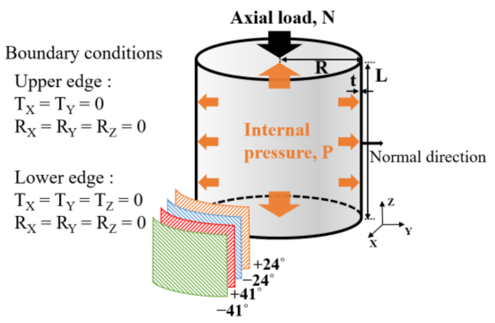
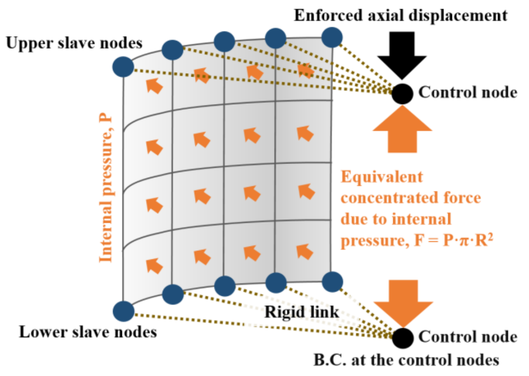
2.2. Modeling Techniques for Compressive Force and Internal Pressure

In this study, nonlinear post-buckling analyses are performed using the Newton-Raphson method along with the displacement control method in ABAQUS to analyze the buckling behavior of the composite cylinder under axial compression. The displacement control method uses the axial displacement instead of the axial compressive force. The enforced axial displacement is applied to the control nodes located at the center of the top and bottom surfaces of the cylinder. The control nodes are connected rigidly to the edge of the thin-walled composite cylinder (Figure 3); therefore, the applied displacement is transmitted to the edge of the cylinder with a uniform magnitude [26]. Furthermore, artificial damping of 5% is applied for numerical stabilization to dissipate the released strain energy using an artificial velocity for each node in the nonlinear static analysis when local instabilities occur [26,27,28,29,30]. The internal pressure on the curved side surfaces of a cylinder is represented by distributed pressure loads. The top and bottom surfaces of a propellant tank are usually designed in various shapes, such as spheres or ellipses; however, for simplicity, rigid circular plates are used for the top and bottom surfaces in this study. Thus, the internal pressure on the top and bottom surfaces of the thin-walled composite cylinder is modeled with the equivalent concentrated forces, which are represented as F = P·π·R2 and applied to the control nodes (Figure 3). The magnitude of the internal pressure is maintained while axial compression is applied to the cylinder for post-buckling analyses.

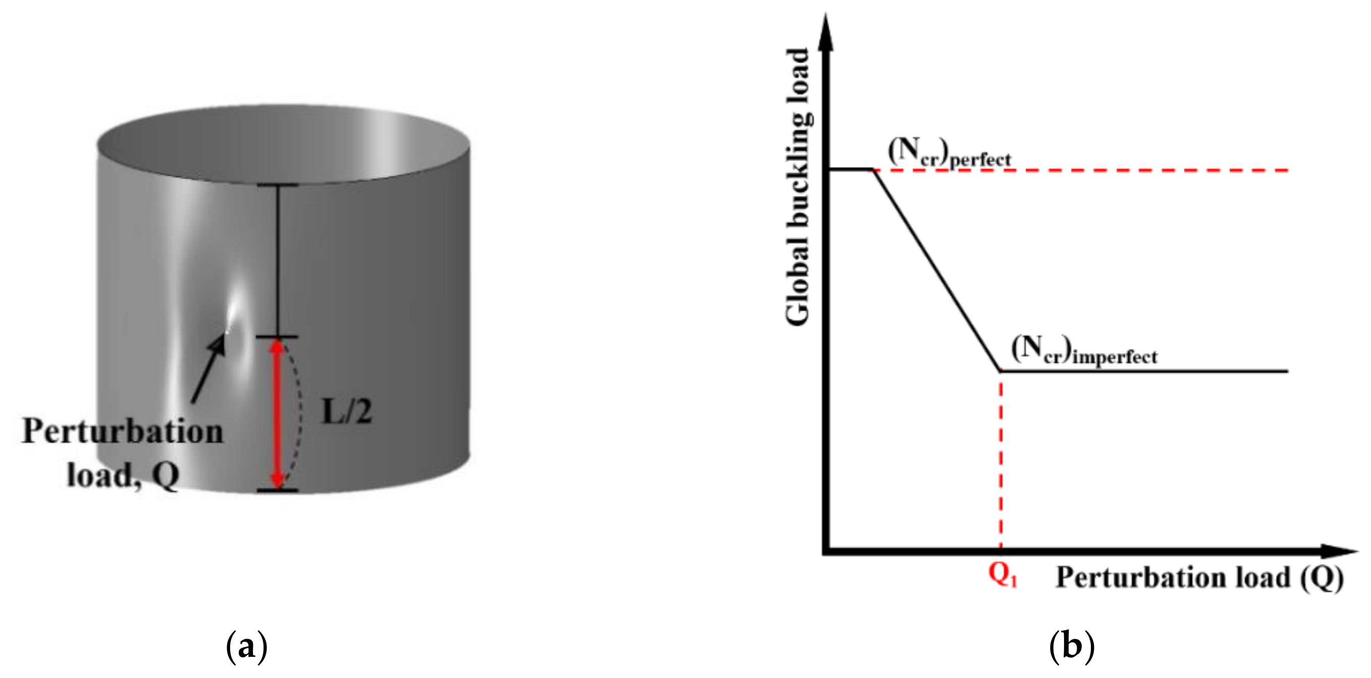
2.3. Initial Imperfection Modeling and Post-Buckling Analysis

The geometric initial imperfection of a thin shell structure is defined as the deviation from its idealized geometry and is known as one of the primary sources, which reduces the buckling load from the linear buckling analysis [31,32,33]. Therefore, in this study, the geometric initial imperfection only is considered for simplicity, although other types of initial imperfections such as loading and boundary initial imperfections are also important for the derivation of knockdown factors. Since the geometric initial imperfection is unknown before measuring it and the measured imperfection data for the Z07 composite thin-walled composite cylinder are not available in the public domain, the SPLA [16] is applied to model the geometric initial imperfection of the thin-walled composite cylinder in this study. As the SPLA can appropriately model the geometric initial imperfection of thin-walled cylinders, it was used intensively for post-buckling analyses in the SBKF [3] and DESICOS [6,7] projects. There is a limit to obtaining the lower bound of buckling knockdown factors for thin-walled composite cylinders when considering the geometric initial imperfection only because the buckling load can be reduced significantly when other initial imperfections, such as loading and boundary initial imperfections, are also considered. In other words, the geometric initial imperfection does not necessarily provide the lower bound of the buckling knockdown factors in all cases [34]; however, it is assumed that the geometric initial imperfection modeling is sufficient only when the effect of internal pressure on the knockdown factor is investigated for thin-walled composite cylinders. In addition, since the geometric initial imperfection of a thin-walled shell structure is independent of loading conditions, the SPLA is enough to study the trend of the amount of increment in the buckling knockdown factors due to internal pressure when the geometric initial imperfection only is considered. The procedures of nonlinear post-buckling analysis using the SPLA [26,27,28,29,30] used in this study are as follows.
First, the perturbation load (Q) of the SPLA is applied in the centripetal direction of a perfect cylinder (without the geometric initial imperfection) at the middle of the length of the cylinder (Figure 4a) to represent the geometric initial imperfection of a cylinder. A nonlinear static analysis is conducted in this step to obtain the deformed shape under a specified Q. This deformed cylinder represents the cylinder with the geometric initial imperfection. The deformed configuration of a cylinder is used in the following procedure in a stress-free state by adjusting the nodal coordinates of the finite element model to represent the geometric initial imperfection [35]. The range of Q values is dependent on the cylinder’s stiffness. Since the length and thickness of a cylinder have an influence on the cylinder’s stiffness, the value of Q considered in the SPLA may be different for the thin-walled composite cylinders with various geometric properties. Second, the internal pressure is applied to the cylinder using the method described in Section 2.2. If the internal pressure is not considered, this procedure is not required. Third, the axial displacement is applied to the cylinder for the post-buckling analysis using the Newton-Raphson method explained in Section 2.2. It is noteworthy that the internal pressure is still applied with a constant magnitude in this step. Finally, the entire analysis is repeated until the global buckling load ((Ncr)imperfect) converges with increasing the Q, as shown in Figure 4b. When the Q exceeds a certain value of perturbation load (Q1, Figure 4b), The global buckling load ((Ncr)imperfect) does not decrease but is almost constant.
Using the converged (Ncr)imperfect and the global buckling load without the geometric initial imperfection ((Ncr)perfect), the buckling knockdown factor, γ, is derived as
γ = ( N cr ) imperfect ( N cr ) perfect

3. Results

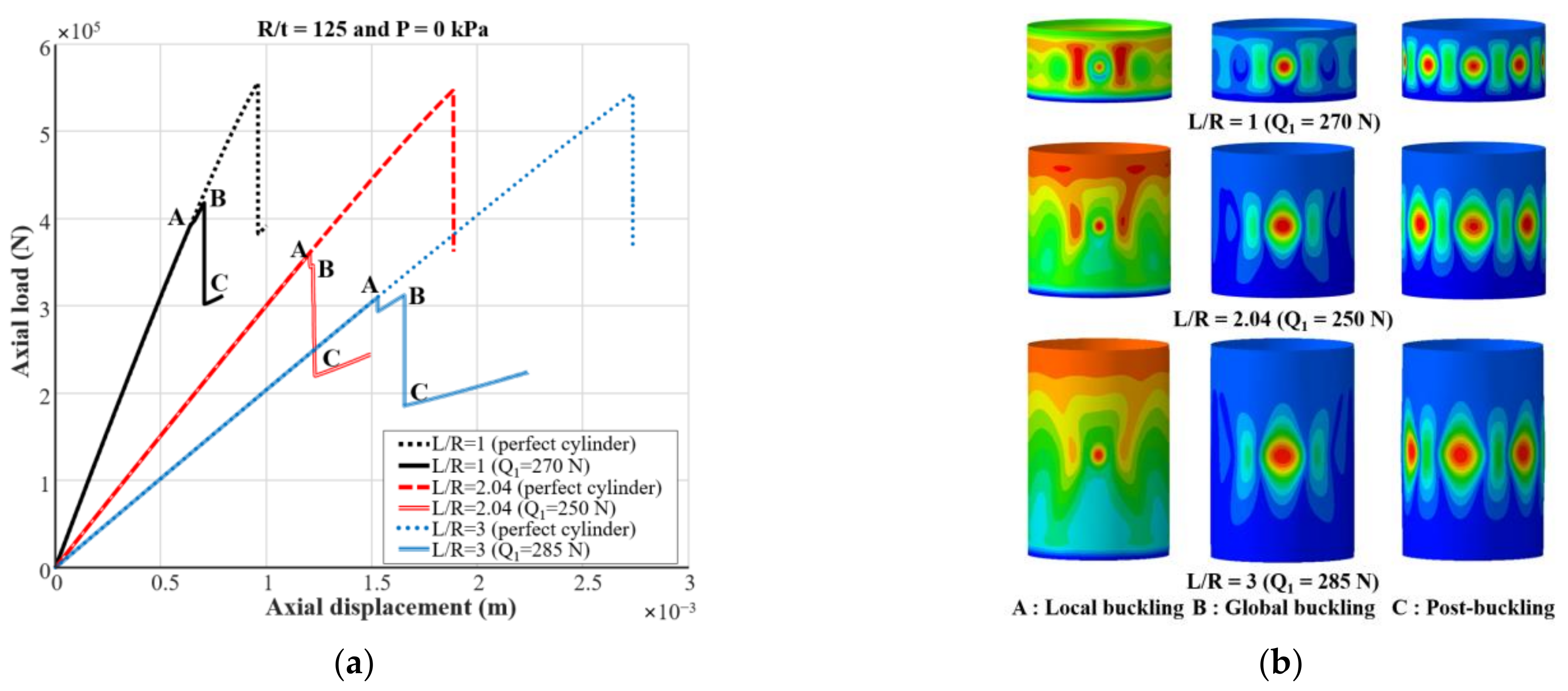
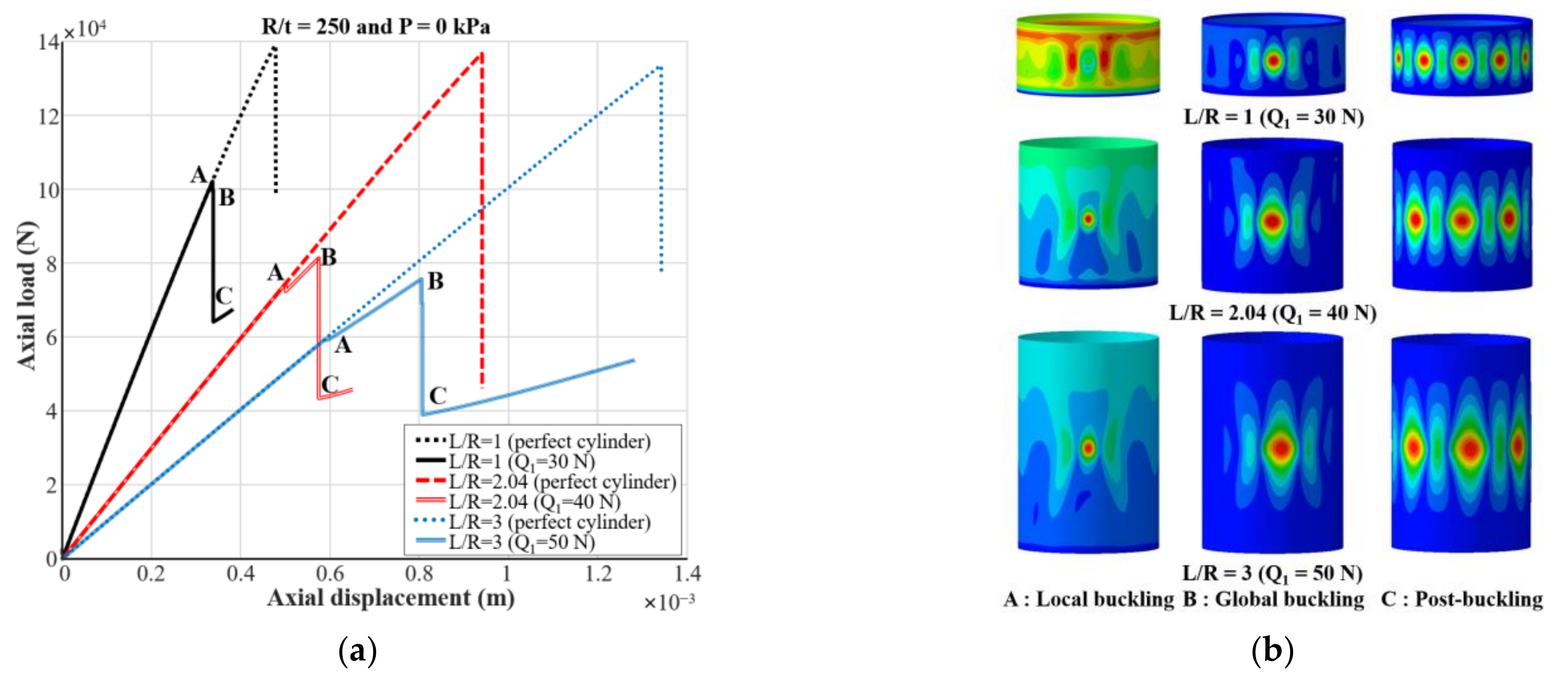
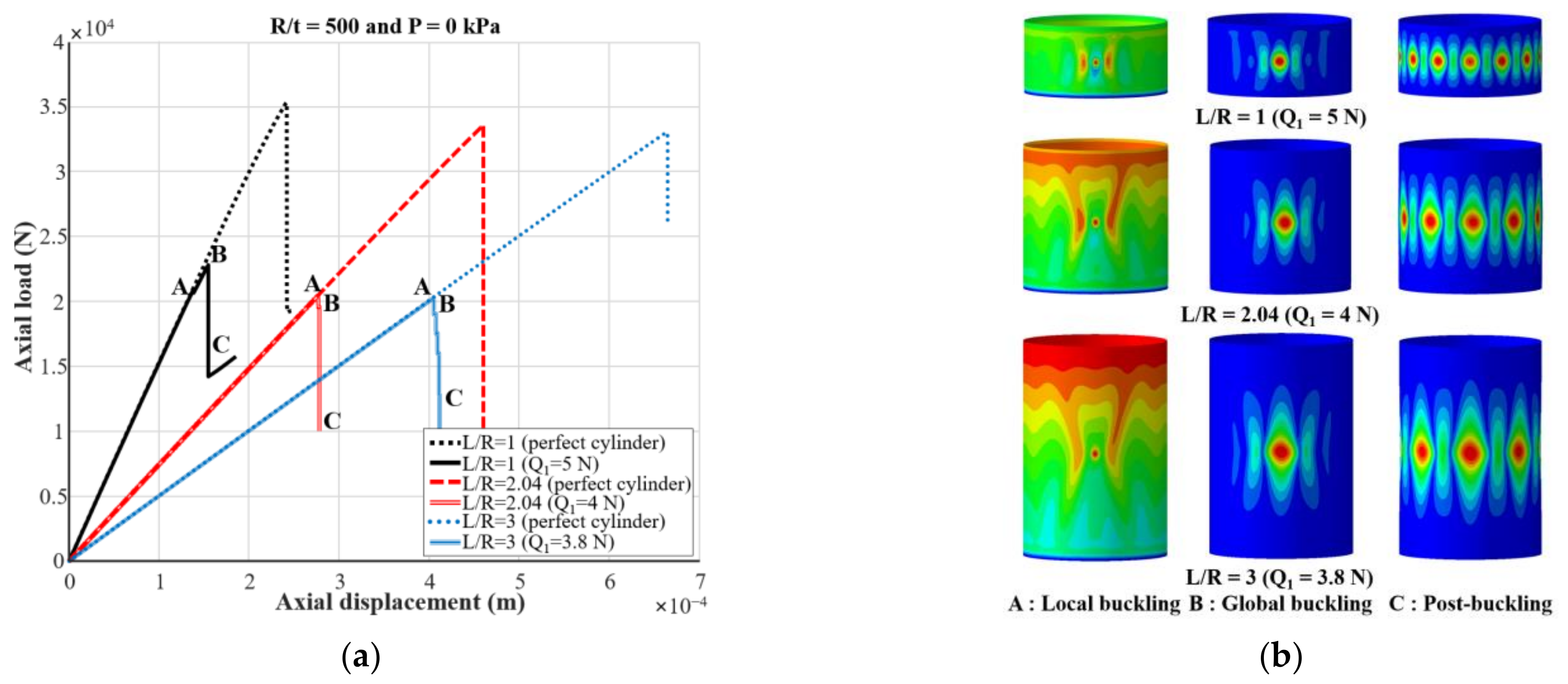
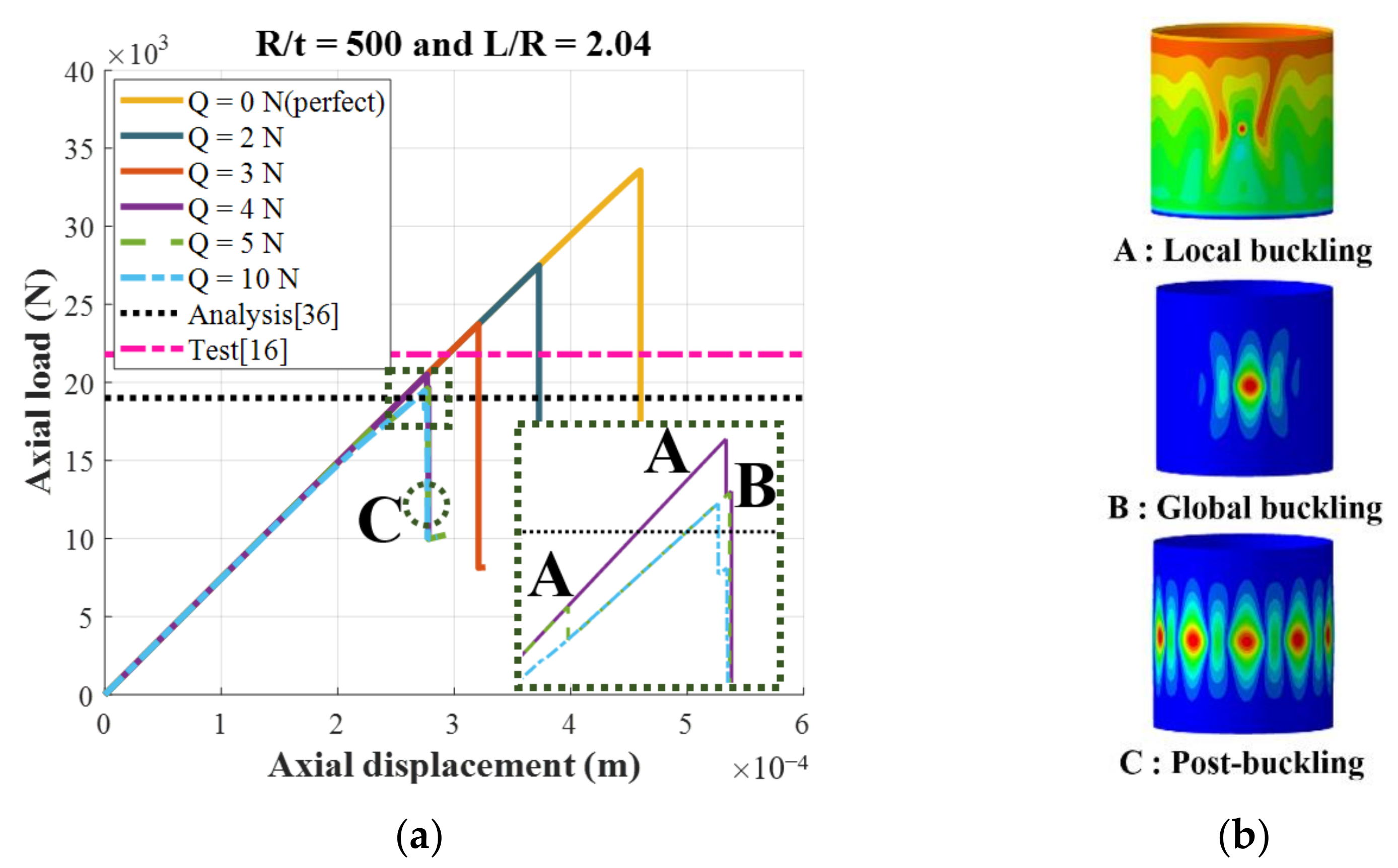
3.1. Nonlinear Post-Buckling Analyses without Internal Pressure

First, the modeling and analysis techniques are validated for the composite cylinder under axial compressive force only. For this validation, a Z07 thin-walled composite cylinder [16] is considered, as shown in Table 1. Figure 5 shows the results of the nonlinear post-buckling analyses for the Z07 thin-walled composite cylinder. As illustrated in Figure 5a, the (Ncr)perfect is predicted to be 33.57 kN. As Q increases, the global buckling load decreases and then converges. At a Q1 of 4N, local buckling (A) occurs. After the local buckling, (Ncr)imperfect (B) is converged to 19.66 kN. The global buckling load from the previous analysis using SPLA is 19.00 kN [36]. The difference of the (Ncr)imperfect between the present and previous [36] analyses is 3.47%. The measured global buckling load from the buckling test is reported as the value of 21.80 kN [16]. The relative error of the (Ncr)imperfect between the present analysis and buckling test [16] is 9.82%, and the error may have been caused by various uncertainties such as material properties, boundary conditions, and loading conditions in the buckling test. Therefore, based on the comparison between the present analysis and the previous prediction [36] and test [16], it is believed that the finite element modeling and post-buckling analysis methods for thin-walled composite cylinders under axial compression are validated appropriately. The buckling shapes at a Q1 are plotted in Figure 5b. In the figure, the local buckling (A) is caused by the Q, and the global buckling (B) waves spread in the circumferential direction at the side where the perturbation load is applied as the axial compressive load increases. After the global buckling, the buckling waves spread in the circumferential direction on the curved side surfaces of the cylinder, and post-buckling (C) is observed.
Using the present analysis methods, thin-walled composite cylinders with various shell thickness ratios (R/t = 125, 250, and 500) and slenderness ratios (L/R = 1, 2.04, and 3) are considered when only axial compression is applied without the internal pressure (Figure 6, Figure 7 and Figure 8). Figure 6a illustrates the load-displacement curves for the cylinders with R/t = 125. For the perfect cylinders with L/R = 1, 2.04, and 3, the (Ncr)perfect values are calculated to be 555.71, 546.85, and 543.89 kN, respectively. The global buckling loads for L/R = 2.04 and 3 are lower by 1.59% and 2.13%, respectively, compared with the result of L/R = 1. However, when the geometric initial imperfection is considered, the (Ncr)imperfect of the cylinders with L/R = 1, 2.04, and 3 are calculated to be 418.12, 346.40, and 312.53 kN, respectively. The results for L/R = 2.04 and 3 are lower by 17.15% and 25.25%, respectively, than the value for L/R = 1. As shown in Figure 6b, in all cases, the local buckling (A), global buckling (B), and post-buckling (C) are quite similar to one another.
The nonlinear post-buckling analysis results for the cylinders with R/t = 250 are presented in Figure 7. As shown in Figure 7a, the (Ncr)perfect values with L/R = 1, 2.04, and 3 are predicted to be 139.09, 136.76, and 133.54 kN, respectively. These loads with L/R = 2.04 and 3 are lower by 1.68% and 3.99%, respectively, compared with the value for L/R = 1. Meanwhile, the (Ncr)imperfect values are 99.81, 81.37, and 75.81 kN for the cylinders with L/R = 1, 2.04, and 3, respectively. The global buckling loads for L/R = 2.04 and 3 are lower than the value for L/R = 1 by 18.48% and 24.05%, respectively. The local buckling (A), global buckling (B), and post-buckling (C) shapes are shown in Figure 7b. The deformed configurations at local buckling (A) and global buckling (B) are similar to the previously reported results (Figure 6b).
For the cylinders with R/t = 500 (Figure 8a), the (Ncr)perfect with L/R = 1, 2.04, and 3 are 35.36, 33.57, and 33.01 kN, respectively. The global buckling loads ((Ncr)perfect) for L/R = 2.04 and 3 are lower by 5.06% and 6.65%, respectively, compared with the global buckling load of the cylinder with L/R = 1. Furthermore, the global buckling loads of imperfect cylinders ((Ncr)imperfect) with L/R = 1, 2.04, and 3 are calculated as 22.86, 19.66, and 19.13 kN, respectively. The results for L/R = 2.04, and 3 are lower than the value for L/R = 1 by 14% and 16.32%, respectively. The deformed shapes in the local buckling (A), global buckling (B), and post-buckling (C) states considering different L/R ratios are shown in Figure 8b.
The results obtained from Figure 6, Figure 7 and Figure 8 can be summarized as follows. As the R/t ratio of the cylinder increases from 125 to 250 and 500 for a given L/R ratio, while the radius (R) is fixed, the global buckling loads with and without the geometric initial imperfection decrease approximately by 75% to 95%. In addition, the global buckling loads with and without the geometric initial imperfection decrease as the L/R ratio increases for a specified R/t ratio. However, for both cases with and without geometric initial imperfection, the reduction rate in the global buckling load with the increase in the R/t ratio is greater than that with the increase in the L/R ratio. Furthermore, the reduction in (Ncr)imperfect is higher than that of (Ncr)perfect.

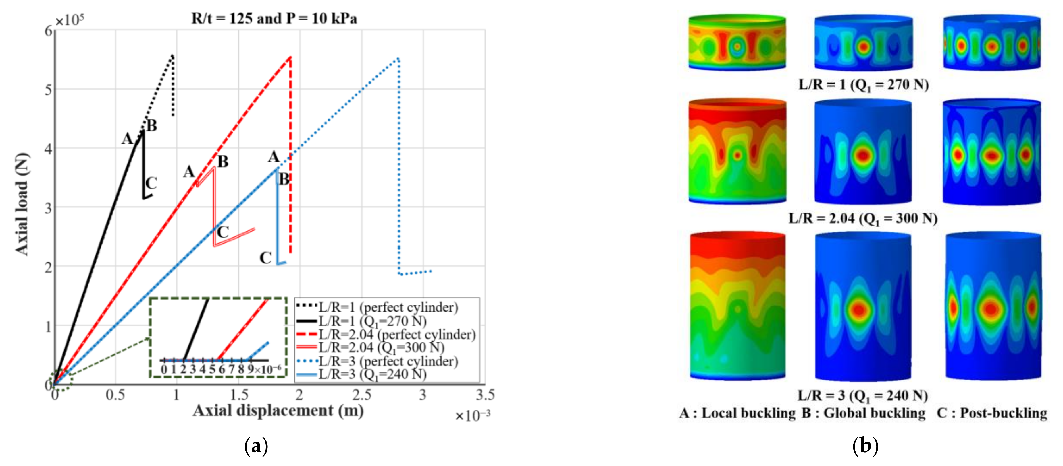
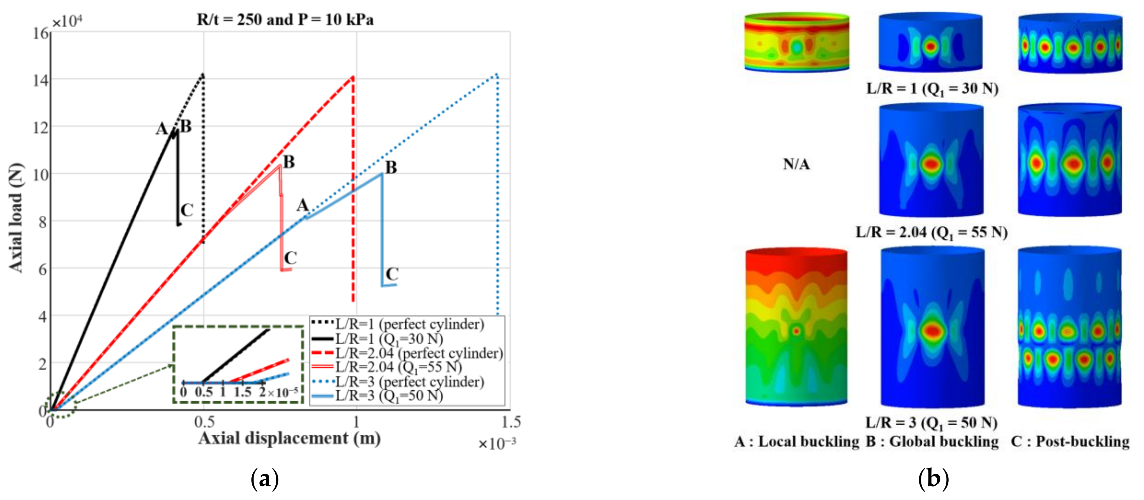
3.2. Nonlinear Post-Buckling Analyses with Internal Pressure

In this section, an internal pressure (P) of 10 kPa is additionally considered to the model used in Section 3.1. Figure 9, Figure 10 and Figure 11 show the results of post-buckling analyses of the thin-walled composite cylinders under both axial compression and internal pressure when various geometric properties are considered.
In the load-displacement curves for the cylinders with R/t = 125 (Figure 9a), similar to the previous results with axial compression only, the global buckling loads with and without the geometric initial imperfection decrease when the L/R ratio increases. For the cylinders with L/R = 1, 2.04, and 3, the (Ncr)perfect are 558.24, 553.58, and 553.33 kN, respectively. The global buckling loads for L/R = 2.04, and 3 are less than 1% lower than the result of the cylinder with L/R = 1, implying similar values. By contrast, when the geometric initial imperfection is taken into account, the (Ncr)imperfect for the cylinders with L/R = 1, 2.04, and 3 are predicted to be 429.20, 367.67, and 339.90 kN, respectively. The calculated global buckling loads for L/R = 2.04 and 3 are lower than the results for L/R = 1 by 14.34% and 20.81%, respectively. However, unlike the results considering only compressive forces, axial shortening is observed in the load-displacement curves when the internal pressure is applied to the cylinder before axial compression. The magnitude of the axial shortening caused by the internal pressure is greater for the cylinders with a larger L/R ratio. In Figure 9b, the deformed configurations with L/R = 1, 2.04, and 3 are similar to the results of the cylinders under axial compression, as previously shown in Figure 6b.
Figure 10 shows the nonlinear post-buckling analyses considering both the internal pressure and axial compressive force of the cylinders with R/t = 250. As shown in Figure 10a, the (Ncr)perfect values for L/R = 1, 2.04, and 3 are calculated to be 142.36, 140.94, and 142.33 kN, respectively. The (Ncr)perfect values decrease by 1.00% and 0.02% as the L/R ratio increases from 1 to 2 and 3, respectively. Therefore, the (Ncr)perfect is almost constant when the L/R ratio varies. However, the (Ncr)imperfect for the cylinders with L/R = 1, 2.04, and 3 are 118.66, 103.64, and 100.17 kN, respectively. Meanwhile, the (Ncr)imperfect for the cylinders of L/R = 2.04 and 3 are lower by 12.66% and 15.58%, respectively, compared with the value for L/R = 1. The axial shortening due to the internal pressure before the axial compressive force is applied is greater than the result for R/t = 125, as shown in Figure 9a. The deformed configurations of the cylinders with R/t = 250 are presented in Figure 10b. As shown in the figure, local buckling (B) is not observed for the case with L/R = 2.04. The buckling shapes for the cases with L/R = 1 and 3 show local buckling (A), global buckling (B), and post-buckling (C). However, the post-buckling shape with L/R = 3 shows two half-waves in the axial direction, which is different from the results without the internal pressure (one half-wave in the axial direction) given previously in Figure 7b.
For the cylinders with R/t = 500 shown in Figure 11a, the (Ncr)perfect is 37.91 kN for L/R = 1 and 37.86 kN for both cases with L/R = 2.04 and 3; hence, the (Ncr)perfect with L/R = 2.04 and 3 are reduced identically to 0.13% compared with the result for L/R = 1. The (Ncr)imperfect for L/R = 1, 2.04, and 3 are predicted to be 34.14, 31.20, and 30.22 kN, respectively. The global buckling loads for L/R = 2.04 and 3 are lower by 8.61% and 11.48%, respectively, compared with the result of the cylinder for L/R = 1. At a given L/R ratio, the magnitude of axial shortening is significantly larger compared with the results for the previous cases with R/t = 125 and 250. As shown, the magnitude of axial shortening due to internal pressure increases with the increase in R/t ratio (Figure 9, Figure 10 and Figure 11), and the effect of the internal pressure becomes more prominent when the thickness of the composite cylinder is reduced. Moreover, it is guessed that the elastic coupling behavior of composite laminates and Poisson’s effect of composite laminates result in the axial shortening from the internal pressure before axial compression. This is because the cylinder is compressed in the axial direction by the internal pressure, although the tensile pressurized load in the cylinder’s top, bottom, and curved side surfaces is applied simultaneously. As shown in Figure 11b, no local buckling (A) occurs for L/R = 3, and the post-buckling states (C) for L/R = 1, 2.04, and 3 show two half-waves in the axial direction.

3.3. Effect of Internal Pressure on Global Buckling Load

Figure 12 shows a summary of the global buckling loads with and without the internal pressure, shown in Figure 6, Figure 7, Figure 8, Figure 9, Figure 10 and Figure 11. For a specified R/t ratio, the global buckling loads with and without the geometric initial imperfection decrease as the L/R ratio increases (i.e., the length (L) of the cylinder increases, while the radius (R) of the cylinder is fixed) for the cylinders with and without the internal pressure. Furthermore, the reduction in the (Ncr)imperfect for L/R = 2.04 and 3 compared with the result for L/R = 1 is greater than that of the perfect cylinder for both cases with and without the internal pressure. As shown in Figure 12, the internal pressure improves the global buckling loads for both cases with and without the geometric initial imperfection. In addition, compared with the global buckling load with the axial compressive force only, the increase in the global buckling load due to the internal pressure is clearly observed for the larger L/R ratio or R/t ratio. For the perfect cylinders, the thinnest and longest model (R/t = 500 and L/R = 3) shows the highest increase in the global buckling load (14.69%), and the lowest increase of 0.46% is observed for the thickest and shortest model (R/t = 125 and L/R = 1) compared with the results without the internal pressure. However, for the geometrically imperfect cylinders with the internal pressure, the global buckling load increases by 57.97% for the thinnest and longest model (R/t = 500 and L/R = 3) and by 2.65% for the thickest and shortest model (R/t = 125 and L/R = 1) compared with the global buckling loads without the internal pressure. The highest increase in the (Ncr)imperfect due to the internal pressure is not observed for the thinnest and longest model (R/t = 500 and L/R = 3) but is observed for the cylinder with R/t = 500 and L/R = 2.04. Nevertheless, the difference in the increase in the global buckling load (Ncr)imperfect due to the internal pressure between the two cylinder models (L/R = 2.04 and 3 with R/t = 500) is less than 1%. This difference may be caused by the numerical error because a nonlinear analysis is conducted using the iterative method with different Q values in this study. Therefore, for the cylinders with R/t = 500, it can be considered that the change in the global buckling load due to the internal pressure is almost identical for cases with L/R = 2.04 and 3. Consequently, it is concluded that the effect of the internal pressure on the thin-walled composite cylinder with or without the initial imperfection is greater for cylinders with higher R/t and L/R ratios. In addition, the increase in (Ncr)imperfect because the internal pressure is higher than that in (Ncr)perfect. For example, for the model with R/t = 500 and L/R = 2.04, the (Ncr)perfect with an internal pressure (P) of 10 kPa is 37.86 kN, which is a 12.78% increase compared with the result considering only the compressive force. The (Ncr)imperfect with an internal pressure (P) of 10 kPa is 31.20 kN, which is 58.70% higher compared with the result considering only compression. The increase in (Ncr)imperfect due to internal pressure is more than about four times higher than that in (Ncr)perfect. As one can see, the internal pressure of the thin-walled composite cylinder reduces the effect of the geometric initial imperfection.

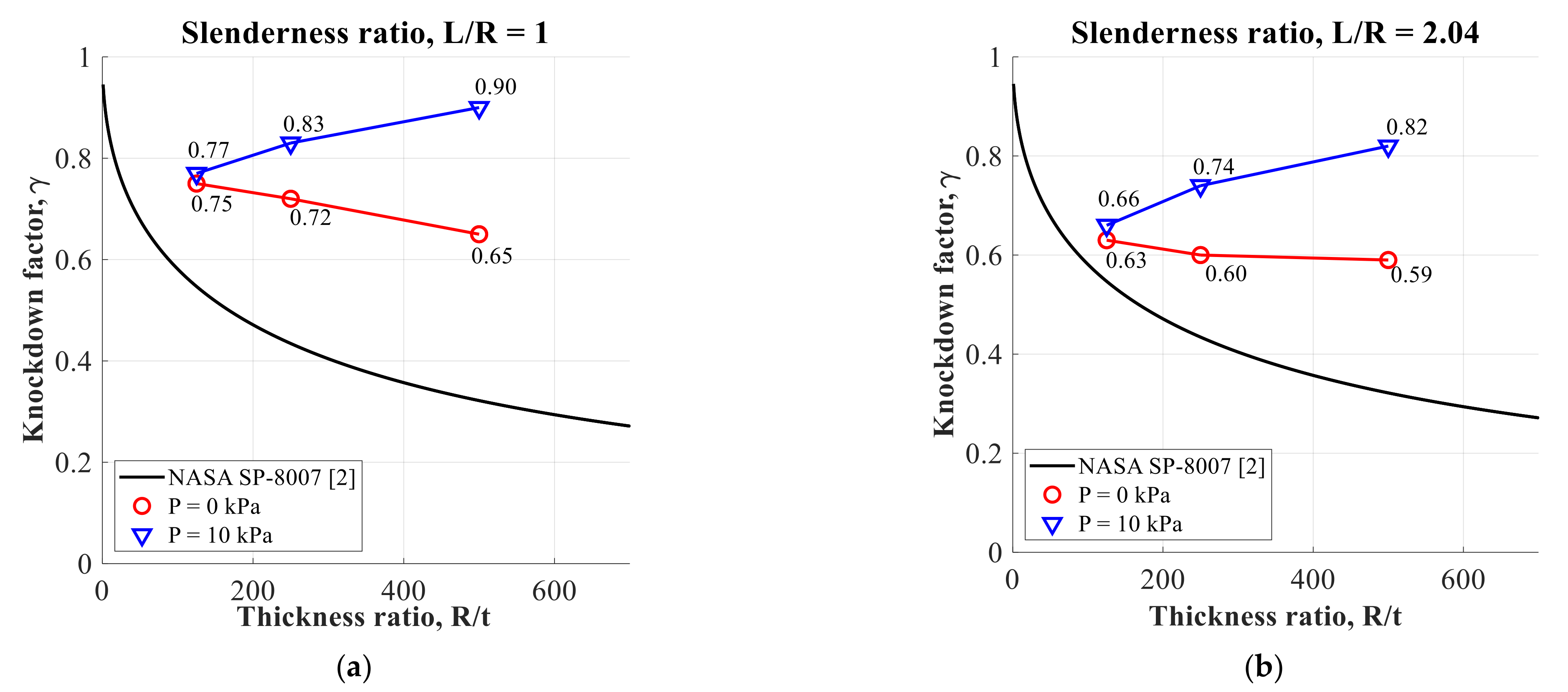
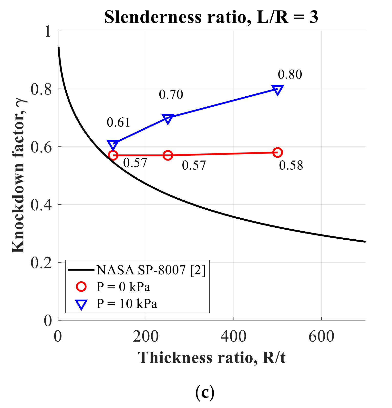
3.4. Effect of Internal Pressure on Buckling Knockdown Factor

Figure 13 shows the derived buckling knockdown factors of the thin-walled composite cylinders using the previous results for global buckling loads. The red circles represent the knockdown factors considering only the axial compressive forces. The blue triangles represent the buckling knockdown factors with both axial compressive forces and internal pressure.
First, the knockdown factors derived in this study and NASA’s results [2] are compared. For both cases with and without the internal pressure, the difference in the buckling knockdown factors between this study and NASA’s result [2] increases as the cylinder’s thickness become thinner for a specified L/R ratio. This is because NASA’s design criteria [2] are based on buckling tests from the 1930s to 1960s; therefore, state-of-the-art manufacturing processes and advanced materials for modern thin-walled cylinders are not included, and the geometric initial imperfection becomes more severe when the thickness of the cylinder decreases (i.e., thinner cylinders). Similarly, as the L/R ratio decreases with and without the internal pressure, the difference in the buckling knockdown factors between this study and NASA’s buckling criteria [2] increases for the given R/t ratio. It is observed that NASA’s buckling criteria [2] are overly conservative for cylinders with lower L/R ratios because they assumed that the effect of the length of the cylinder on the buckling knockdown factors is negligible [37], although the length of the cylinder affects the buckling behavior of the thin-walled cylinder.
Next, the effect of the R/t ratio or L/R ratio on the buckling knockdown factor derived in this study is summarized. When the L/R ratio increases for a given R/t ratio, the buckling knockdown factors derived from this study decrease for both cases with and without the internal pressure; hence, the sensitivity of the thin-walled composite cylinders to the geometric initial imperfection increases. This is because, as previously described, (Ncr)imperfect decreases more than (Ncr)perfect when the L/R ratio increases. By contrast, when the R/t ratio increases for a given L/R ratio, the knockdown factor trends with and without the internal pressure are different. The buckling knockdown factors with compressive forces only decrease as the R/t ratio increases. In particular, for the case of L/R = 1, the reduction in the buckling knockdown factor is approximately 13.33% as the R/t ratio increases from 125 to 500. The buckling knockdown factor for L/R = 2.04 decreases by 6.35% when the R/t ratio increases from 125 to 500. For the case with L/R = 3, the buckling knockdown factor is nearly constant as the R/t ratio increases from 125 to 500. When only axial compression is considered, the decrease in the buckling knockdown factor with an increase in the R/t ratio is greater for a cylinder with a smaller L/R ratio than that for a cylinder with a larger L/R ratio. However, considering both the axial compression and the internal pressure, it is observed that the buckling knockdown factor does not decrease but increases when the R/t ratio increases for a specified L/R ratio. This is because a thinner cylinder (higher R/t ratio) is more sensitive to the internal pressure than a thicker cylinder (lower R/t ratio); therefore, the effect of the internal pressure, which reduces the geometric initial imperfection, is more prominent for the thinner cylinder. Furthermore, the rate of increase in the buckling knockdown factor due to internal pressure is higher for the longer cylinder (higher L/R ratio). Considering the internal pressure, when the R/t ratio increases from 125 to 500, the buckling knockdown factor increases by 16.88% for the cylinder with L/R = 1, by 24.24% for the cylinder with L/R = 2.04, and by 31.15% for the cylinder with L/R = 3. This is because the effect of the internal pressure on the thin-walled composite cylinder is greater when the cylinder is longer (higher L/R ratio), as previously described in Section 3.3. The buckling knockdown factors considering both the compressive force and the internal pressure are derived to be higher than the buckling knockdown factors considering only compressive force for all the R/t and L/R ratios considered. The results show that the buckling knockdown factors may be improved when the internal pressure of the thin-walled composite cylinder is considered simultaneously with the compressive force.

4. Conclusions

The buckling knockdown factors of thin-walled composite cylinders under both axial compressive force and internal pressure were numerically derived in this study. Thin-walled composite cylinders with R/t = 125, 250, and 500 and L/R = 1, 2.04, and 3 were used to consider the various geometric properties of the cylinder. Post-buckling analyses were conducted using a nonlinear finite element analysis program, ABAQUS, for thin-walled composite cylinders. The SPLA was applied to represent the geometric initial imperfection since the measured imperfection data of the present thin-walled composite cylinders were not available in the public domain. In the case involving only the axial compressive force, both the buckling knockdown factors and global buckling loads decreased as the R/t ratio increased for a specified L/R ratio or as the L/R ratio increased for a given R/t ratio. When the axial compressive force and the internal pressure (10 kPa) were simultaneously applied to the thin-walled composite cylinder, the global buckling loads decreased when the R/t ratio increased or the L/R ratio increased. The buckling knockdown factor decreased as the L/R ratio increased for a given R/t ratio; however, it increased when the R/t ratio increased for a specified L/R ratio.
The buckling knockdown factors obtained for the different R/t and L/R ratios under both axial compression and internal pressure were higher by 2.67% to 38.98% compared with the values with axial compression only. These results indicate that the buckling knockdown factors may be enhanced by considering the internal pressure for thin-walled composite cylinders; hence, it is believed that a much higher level of lightweight design for thin-walled composite propellant tanks is possible.
This study investigated for the first time the amount of increase in buckling knockdown factors due to the internal pressure thoroughly for thin-walled composite cylinders with various geometric properties while the elastic coupling effect of composite laminates was maintained, and it demonstrated the possibility of improving the buckling knockdown factors when considering the internal pressure of axially compressed thin-walled composite cylinders; however other types of imperfection such as loading or boundary imperfection should be considered for the derivation of the buckling knockdown factors in the future. In addition, not the maximum internal pressure but the minimum internal pressure to operate the propellant tanks should be used when the internal pressure is considered for the derivation of the buckling knockdown factor since the maximum internal pressure may give unrealistic high knockdown factors. Furthermore, the buckling tests of thin-walled composite cylinders under both axial compression and internal pressure will be conducted in the near future. Using the measured imperfection data of the thin-walled composite cylinders and the global buckling loads obtained from the test, it will be investigated that the SPLA can be used to derive the buckling knockdown factor under both axial compression and internal pressure.

Author Contributions

Conceptualization, J.-S.P. and K.L.; methodology, C.-H.S.; software, D.-Y.K.; validation, D.-Y.K.; formal analysis, D.-Y.K.; investigation, D.-Y.K.; resources, J.-S.P.; data curation, D.-Y.K.; writing—original draft preparation, D.-Y.K.; writing—review and editing, J.-S.P.; visualization, D.-Y.K.; supervision, J.-S.P.; project administration, J.-T.Y. and Y.-H.Y.; funding acquisition, J.-S.P. All authors have read and agreed to the published version of the manuscript.

Funding

This work was supported by research on the preceding technologies for geostationary satellite launch vehicle of the Korea Aerospace Research Institute (KARI), the Korea Space Launch Vehicle (KSLV-II) funded by the Ministry of Science and ICT (MSIT, Korea).

Data Availability Statement

The numerical data used to support the findings of this study are included within the article.

Conflicts of Interest

The authors declare no conflict of interest.

References

  1. Salt, D.J. Space operations for a newspace era. In Proceedings of the SpaceOps 2010 Conference, Huntsville, AL, USA, 25–30 April 2010. [Google Scholar] [CrossRef]
  2. Peterson, J.P.; Seide, P.; Weingarten, V.I. Buckling of Thin-Walled Circular Cylinders–NASA SP-8007. 1968. Available online: https://ntrs.nasa.gov/citations/20205011530 (accessed on 1 May 2020).
  3. Hilburger, M.W. Shell Buckling Knockdown Factor Project Overview and Status, NASA/NF1676L-21449. 2015. Available online: https://ntrs.nasa.gov/citations/20160007439 (accessed on 6 May 2020).
  4. Hilburger, M.W.; Waters, W.A.J.; Haynie, W.T. Buckling Test Results from the 8-Foot-Diameter orthogrid-Stiffened Cylinder Test Article TA01, NF1676L-20067. 2015. Available online: https://ntrs.nasa.gov/citations/20150017037 (accessed on 1 August 2020).
  5. Hilburger, M.W.; Waters, W.A.J.; Haynie, W.T.; Thornburgh, R.P. Buckling Test Results from the 8-Foot-Diameter Orthogrid-Stiffened Cylinder Test Article TA02, NASA/TP-2017-219587, L-20801, NF1676L-26704. 2017. Available online: https://ntrs.nasa.gov/citations/20170005857 (accessed on 1 August 2020).
  6. Degenhardt, R. New robust design guideline for imperfection sensitive composite launcher structures–The DESICOS project. In Proceedings of the 13th European Conference on Spacecraft Structures, Materials and Environment Testing, Braunscheweig, Germany, 1–4 April 2014. [Google Scholar]
  7. Degenhardt, R.; Kling, A.; Zimmermann, R.; Odermann, F.; Araújo, F.C. Chapter Dealing with Imperfection Sensitivity of Composite Structures Prone to Buckling; InTechOpen Ltd.: London, UK, 2012; pp. 1–16. [Google Scholar]
  8. Hao, P.; Wang, B.; Li, G.; Meng, Z.; Tian, K.; Zeng, D.; Tang, X. Worst multiple perturbation load approach of stiffened shells with and without cutouts for improved knockdown factors. Thin-Walled Struct. 2014, 82, 321–330. [Google Scholar] [CrossRef]
  9. Hao, P.; Wang, B.; Li, G.; Meng, Z.; Tian, K.; Tang, X. Hybrid optimization of hierarchical stiffened shells based on smeared stiffener method and finite element method. Thin-Walled Struct. 2014, 82, 46–54. [Google Scholar] [CrossRef]
  10. Zhao, Y.; Chen, M.; Yang, F.; Zhang, L.; Fang, D. Optimal design of hierarchical grid-stiffened cylindrical shell structures based on linear buckling and nonlinear collapse analyses. Thin-Walled Struct. 2017, 119, 315–323. [Google Scholar] [CrossRef]
  11. Wang, B.; Tian, K.; Zhou, C.; Hao, P.; Zheng, Y.; Ma, Y.; Wang, J. Grid-pattern optimization framework of novel hierarchical stiffened shells allowing for imperfection sensitivity. Aerosp. Sci. Technol. 2017, 62, 114–121. [Google Scholar] [CrossRef]
  12. Wang, B.; Du, K.; Hao, P.; Zhou, C.; Tian, K.; Xu, S.; Ma, Y.; Zhang, X. Numerically and experimentally predicted knockdown factors for stiffened shells under axial compression. Thin-Walled Struct. 2016, 109, 13–24. [Google Scholar] [CrossRef]
  13. Orifici, A.; Bisgani, C. Perturbation-based imperfection analysis for composite cylindrical shells buckling in compression. Compos. Struct. 2013, 106, 520–528. [Google Scholar] [CrossRef] [Green Version]
  14. Bisgani, C. Composite cylindrical shells under static and dynamic axial loading: An experimental campaign. Prog. Aerosp. Sci. 2015, 78, 107–115. [Google Scholar] [CrossRef]
  15. Takano, A. Statistical knockdown factors of buckling anisotropic cylinders under axial compression. J. Appl. Mech. 2012, 79. [Google Scholar] [CrossRef]
  16. Hühne, C.; Rolfes, R.; Breitbach, E.; Teßmer, J. Robust design of composite cylindrical shells under axial compression—Simulation and validation. Thin-Walled Struct. 2008, 46, 947–962. [Google Scholar] [CrossRef]
  17. Wagner, H.N.R.; Hühne, C. Robust knockdown factors for the design of cylindrical shells under axial compression: Potentials, practical application and reliability analysis. Int. J. Mech. Sci. 2018, 135, 410–430. [Google Scholar] [CrossRef]
  18. Degenhardt, R.; Bethge, A.; Kling, A.; Zimmermann, R.; Rohwer, K. Probabilistic approach for better buckling knockdown factors of CFRP cylindrical shells–Tests and analyses. In Proceedings of the 18th Engineering Mechanics Division Conference of the American Society of Civil Engineers, Blacksburg, VA, USA, 3–6 June 2007. [Google Scholar]
  19. Wagner, H.N.R.; Hühne, C.; Janssen, M. Buckling of cylindrical shells under axial compression with loading imperfections: An experimental and numerical campaign on low knockdown factors. Thin-Walled Struct. 2020, 151, 106764. [Google Scholar] [CrossRef]
  20. Geier, B.; Meyer-Piening, H.-R.; Zimmermann, R. On the influence of laminate stacking on buckling of composite cylindrical shells subjected to axial compression. Compos. Struct. 2002, 55, 467–474. [Google Scholar] [CrossRef]
  21. Anonymous, Falcon User’s Guide, SPACE Exploration Technologies Corp. 2020. Available online: https://www.spacex.com/media/falcon-users-guide-2021-08.pdf (accessed on 1 August 2020).
  22. Anonymous, Ariane 5 User’s Manual Issue 5 Revision 2, Arianespace. 2016. Available online: https://www.arianespace.com/wp-content/uploads/2011/07/Ariane5_Users-Manual_October2016.pdf (accessed on 1 October 2020).
  23. Lo, H.; Crate, H.; Schwartz, E.B. Buckling of Thin-Walled Cylinder under Axial Compression and Internal Pressure, NACA/TR-1027. 1951. Available online: https://ntrs.nasa.gov/citations/19930090955 (accessed on 1 January 2021).
  24. Graham, J.B.; Luz, P.L. Preliminary In-Flight Loads Analysis of In-Line Launch Vehicles Using the VLOADS 1.4 Program, NASA/TM-1998-208472. 1998. Available online: https://ntrs.nasa.gov/citations/19980201045 (accessed on 1 June 2020).
  25. Hilburger, M.W. On the Development of Shell Buckling Knockdown Factors for Stiffened Metallic Launch Vehicle Cylinders. In Proceedings of the 2018 AIAA/ASCE/AHS/ASC Structures, Structural Dynamics, and Materials Conference, Kissimmee, FL, USA, 8–12 January 2018. [Google Scholar]
  26. Kim, H.-I.; Sim, C.-H.; Park, J.-S.; Kim, D.-Y.; Yoo, J.-T.; Yoon, Y.H.; Lee, K. Postbuckling analyses and derivations of shell knockdown factors for isogrid-stiffened cylinders under compressive force and internal pressure. J. Korean Soc. Aeronaut. Space Sci. 2020, 48, 653–661. [Google Scholar] [CrossRef]
  27. Kim, H.-I.; Sim, C.-H.; Park, J.-S.; Lee, K.; Yoo, J.-T.; Yoon, Y.-H. Numerical derivation of buckling knockdown factors for isogrid-stiffened cylinders with various shell thickness ratios. Int. J. Aerosp. Eng. 2020. [Google Scholar] [CrossRef]
  28. Sim, C.-H.; Kim, H.-I.; Park, J.-S.; Lee, K. Derivation of knockdown factors for grid-stiffened cylinders considering various shell thickness ratios. Aircr. Eng. Aerosp. Technol. 2019, 91, 1314–1326. [Google Scholar] [CrossRef]
  29. Sim, C.-H.; Park, J.-S.; Kim, H.-I.; Lee, Y.-L.; Lee, K. Postbuckling analyses and derivations of knockdown factors for hybrid-grid stiffened cylinders. Aerosp. Sci. Technol. 2018, 82–83, 20–31. [Google Scholar] [CrossRef]
  30. Sim, C.-H.; Kim, H.-I.; Lee, Y.-L.; Park, J.-S.; Lee, K. Derivations of knockdown factors for cylindrical structures considering different initial imperfection models and thickness ratios. Int. J. Aeronaut. Space Sci. 2018, 19, 626–635. [Google Scholar] [CrossRef]
  31. Koiter, W.T. A Translation of the Stability of Elastic Equilibrium; Management Information Services Ltd.: Detroit, MI, USA, 1970. [Google Scholar]
  32. Kármán, T.V.; Tsien, H.S. The buckling of thin cylindrical shells under axial compression. J. Aeronaut. Sci. 1941, 8, 303–312. [Google Scholar] [CrossRef]
  33. Elishakoff, I. Probabilistic resolution of the twentieth century conundrum in elastic stability. Thin-Walled Struct. 2012, 59, 35–57. [Google Scholar] [CrossRef]
  34. Wagner, H.N.R.; Hühne, C.; Niemann, S.; Khakimova, R. Robust design criterion for axially loaded cylindrical shells- Simulation and validation. Thin-Walled Struct. 2017, 115, 154–162. [Google Scholar] [CrossRef]
  35. Deml, M.; Wunderlich, W. Direct evaluation of the ‘worst’ imperfection shape in shell buckling. Comput. Methods Appl. Mech. Eng. 1997, 149, 201–222. [Google Scholar] [CrossRef]
  36. Wagner, H.N.R.; Hühne, C.; Niemann, S. Constant single-buckling imperfection principle to determine a lower bound for the buckling load of unstiffened composite cylinders under axial compression. Compos. Struct. 2016, 139, 120–129. [Google Scholar] [CrossRef]
  37. Hilburger, M.W. Developing the next generation shell buckling design factors and technologies. In Proceedings of the 53rd AIAA/ASME/ASCE/AHS/ASC Structures, Structural Dynamics and Materials Conference, Honolulu, HI, USA, 23–26 April 2012. [Google Scholar]
Figure 1. NASA’s lower bound of knockdown factors [2].
Aerospace 08 00346 g001
Figure 2. Schematic diagram of the thin-walled composite cylinder.
Aerospace 08 00346 g002
Figure 3. Applications of loads and boundary conditions.
Aerospace 08 00346 g003
Figure 4. Geometric initial imperfection and convergence of global buckling load in SPLA [16]. (a) A perturbation load (Q), (b) Global buckling load vs. perturbation load.
Aerospace 08 00346 g004
Figure 5. Post-buckling analysis results for Z07 composite cylinder. (a) Load-displacement curves, (b) Buckling shapes.
Aerospace 08 00346 g005
Figure 6. Post-buckling analyses results under axial compression for the cylinders R/t = 125. (a) Load-displacement curves, (b) Buckling shapes.
Aerospace 08 00346 g006
Figure 7. Post-buckling analyses results under axial compression for the cylinders R/t = 250. (a) Load-displacement curves, (b) Buckling shapes.
Aerospace 08 00346 g007
Figure 8. Post-buckling analyses results under axial compression for the cylinders R/t = 500. (a) Load-displacement curves, (b) Buckling shapes.
Aerospace 08 00346 g008
Figure 9. Post-buckling analyses results under axial compression and internal pressure (10 kPa) for the cylinders R/t = 125. (a) Load-displacement curves, (b) Buckling shapes.
Aerospace 08 00346 g009
Figure 10. Post-buckling analyses results under axial compression and internal pressure (10 kPa) for the cylinders R/t = 250. (a) Load-displacement curves, (b) Buckling shapes.
Aerospace 08 00346 g010
Figure 11. Post-buckling analyses results under axial compression and internal pressure (10 kPa) for the cylinders R/t = 500. (a) Load-displacement curves, (b) Buckling shapes.
Aerospace 08 00346 g011
Figure 12. Global buckling loads of the thin-walled composite tank models with and without the internal pressure. (a) R/t = 125, (b) R/t = 250, (c) R/t = 500.
Aerospace 08 00346 g012
Figure 13. Buckling knockdown factors of the thin-walled composite tank models considering various geometric properties with and without the internal pressure. (a) L/R = 1, (b) L/R = 2.04, (c) L/R = 3.
Aerospace 08 00346 g013aAerospace 08 00346 g013b
Table 1. Properties of the Z07 thin-walled composite cylinder [16].
PropertyValue
Radius, R (m)0.25
Length, L (m)0.51
Thickness, t (m)0.0005
Ply thickness, tply (m)0.000125
Poisson’s ratio, νLT0.271
Elastic modulus, EL (MPa)125,774
Elastic modulus, ET (MPa)10,030
Shear modulus, GLT (MPa)5555
Lay-up condition (deg)(+24/−24/+41/−41)
Table 2. Properties of the composite cylinders with various thickness ratios and slenderness ratios.
Lay-Up Condition(+24n/−24n/+41n/−41n)
Thickness ratio, R/t125250500
Thickness, t (m)0.0020.0010.0005
Number of plies, n421
Slenderness ratio, L/R12.043
Length, L (m)0.250.510.75
Publisher’s Note: MDPI stays neutral with regard to jurisdictional claims in published maps and institutional affiliations.

