Article

Design of Robust Control System of Magnetic Suspension and Balance System through Harmonic Excitation Simulation

Department of Aeronautical and Mechanical Design Engineering, Korea National University of Transportation, 50 Daehak-ro, Chungju-si 27469, Korea
Aerospace 2021, 8(10), 304; https://doi.org/10.3390/aerospace8100304
Submission received: 31 August 2021 / Revised: 29 September 2021 / Accepted: 13 October 2021 / Published: 15 October 2021
(This article belongs to the Special Issue Vibration Control for Space Application)

Abstract

:
The magnetic suspension and balance system (MSBS) uses magnetic force and moment to precisely control the movement of the test object located at the center of the test section without mechanical contact, and at the same time measure the external force acting on the test object. If such an MSBS is installed around the test section of the wind tunnel so that the position and attitude angle of the test object follow the harmonic function, various vibration tests can be performed on structures subjected to aerodynamic loads without the influence of the mechanical support. Because the control force and moment in the MSBS is generated by a number of electromagnets located around the test section, it is necessary to apply the adaptive control algorithm to the position and attitude control system so that the experiment can be carried out stably despite the sudden performance change of each electromagnet and electric power supply. In this study, a fault-tolerant position and attitude angle control system was designed through an adaptive control algorithm, and the effectiveness was verified through simulation under the condition that the electric power supply of MSBS failed.

1. Introduction

The wind tunnel test is an experiment in which an air flow is artificially generated around a test object having various shapes and changes around the test object are observed accordingly. At the same time, the test object can be fixed in the center of the test section using a support device such as a post, and the forces and moments acting in each axial direction can be measured. However, devices such as stings or struts disturb the air flow in the wind tunnel test section, which hinders obtaining high-precision experimental results. Meanwhile, robotic support devices, such as a HARS (high attitude robotic sting), are sometimes used as a convenient way to change the attitude angle of the test object, but in this case the interference effect by the support device is increased. The magnetic suspension and balance system (MSBS) is designed to eliminate the influence of the support device during wind tunnel testing. MSBS generates magnetic force and moment using electromagnets to levitate a magnetized or permanent magnet embedded test object in the test section. The movement of the test object can be controlled by adjusting the magnetic field generated by the electromagnets, and the force and moment in each axial direction can be analyzed by measuring the amount of electric current inputs to the electromagnets according to each axial control command. Therefore, by using the MSBS, it is possible to conduct vibration tests on the position and attitude angle of the structure to which the aerodynamic load acts while eliminating the influence of the support device [1,2,3,4,5].
The basic concept of the MSBS was first devised by B. A. Holmes of the University of Virginia in 1937. Holmes proposed the use of magnetic force to reduce friction in bearings. Then, in 1954, Laurenceau and Tournier of ONERA successfully applied a magnetic force support device to a wind tunnel test for the first time [6]. Development of an MSBS having a test section of 60 × 60 cm was completed in 2000 by JAXA (Japan Aerospace Exploration Agency). This is the MSBS with the world’s largest test unit. The development started in 1991, and from 1999 it was installed in a low-speed wind tunnel and available for aerodynamic experiments. After conducting airflow testing in low-speed wind tunnel in 2000, wind tunnel experiments are being carried out in earnest [7,8,9]. In addition, several research institutes and universities have developed large and small MSBS, and one of them is MSBS with a 40 × 33 cm test section developed by FIT (Fukuoka Institute of Technology, Japan). The development was started in 1999, six-axis control and calibration was completed in 2004, and various researches have been conducted on aerodynamics acting on spheres and cylinders using the MSBS [10].
Looking at the research trend of a wind tunnel experiment using the MSBS, most of the research focused on eliminating the interference of the support device while motion of test objects was fixed. In 1971, M. Vlajinac and E. E. Covert of MIT conducted an experiment to measure the drag coefficient of spherical objects of various sizes in the subsonic region using the MSBS. The MSBS used in the study had a test section of 10.2 × 10.2 cm, and the experiment was conducted while the five degrees of freedom of the ellipsoidal object, having sizes of 1.875, 2.5, and 3.75 cm, were constrained [11,12]. In 1990, David A. Dress of NASA Langley Research Center conducted an experiment to measure the drag coefficient acting on a spheroid in the low Reynolds number region using the MSBS, which can fix five degrees of freedom of the test object in the test section, of which the size was 27.2 × 31.9 cm. A wind tunnel experiment using a spheroid with a fineness ratio (L/D) of 7.5 was performed, and it was confirmed that the drag coefficient was measured up to 10% smaller due to the influence of the virtual sting installed on the back of the test object [13]. Britcher et al. conducted a study to measure the aerodynamic force acting on ogive cylinders under support interference free conditions through a wind tunnel test using the MSBS [14]. When performing a sting-free wind tunnel test in the ultra-high Reynolds number regimes using cryogenic helium, it is difficult to measure the position and attitude of the test object by optical methods, and EPS (electromagnetic position sensor) had been proposed for the measurement system of the MSBS [15]. Meanwhile, they also conducted researches to expand the usable area of the MSBS away from the existing static tests, and published results on a novel electromagnet array and sensor system which allows the MSBS to stably levitate a test object while the object rotates 360 degrees about a vertical axis [16,17].
Recently, related research is being actively conducted at JAXA, FIT, and Korea Advanced Institute of Science and Technology (KAIST). Sawada et. al., of JAXA used a 60 × 60 cm MSBS to measure the drag coefficient of a spherical object with respect to the Reynolds number. It was the first in the world to measure the drag coefficient of a spherical object in the area of the maximum Reynolds number of 3.5 × 10⁵ using the MSBS without the influence of a supporting device, and the results agreed well with the drag coefficient of a spherical object measured by Vlajinac in 1972 using the MSBS [18]. Higuchi et al. conducted an experiment applying PIV to observe the flow around a cylinder aligned in the wind tunnel direction using the JAXA 60 × 60 cm MSBS in 2006. Unlike the existing wind tunnel experiment, in the wind tunnel experiment using the MSBS, there was no disturbance by the support device. Therefore, the flow around the test object could be accurately observed, and the shear flow reattachment phenomenon according to the fineness ratio of the cylinder was visualized [19,20]. Shinji et al. presented the results of the drag coefficient measurement for cylindrical test objects aligned in the freestream direction with various low fineness ratios through wind tunnel tests using the MSBS. According to this study, it is confirmed that the Strouhal number of the lift force and the side force fluctuated by vortex shedding is 0.15 in common regardless of the fineness ratio of the cylinder model, while the magnitude of fluctuation is related to the ratio [21]. Kawamura et al. of FIT measured the drag coefficient of a spherical object with respect to Reynolds number using the MSBS owned by FIT in 2003. It was confirmed that, as the Reynolds number increased, the drag coefficient was close to the commonly known value of 0.47 [22]. Meanwhile, research was also conducted to use the MSBS for the design of an attitude control system of unmanned aerial vehicles (UAVs) by Lee et al. of KAIST. Since the magnitude and direction of the magnetic force and moment of the MSBS are generated by the control command calculated from the control system, it is possible to arbitrarily adjust them. If the command calculated from the control system for a specific degree of freedom of the test object is zero, the test object is placed in a free motion state in that degree of freedom. Then, when the control command is restored at a desired instant, the corresponding degree of freedom of the test object is constrained by the restored magnetic force or moment. Lee showed that it is possible, utilizing these features, to conduct intensive flight tests while the safety of the UAV is guaranteed through wind tunnel tests using the MSBS [23]. Taking advantage of the fact that it is possible to freely control the force and moment due to magnetic field in the test section of the MSBS, it will be possible to conduct a vibration test of a structure exposed to aerodynamic loads without the influence of the mechanical support.
In order to perform the wind tunnel test using the MSBS stably and to increase the accuracy of the results, it is necessary to increase the command-following performance of the MSBS position and attitude control system, and to design a control system that is robust to environmental changes such as equipment failure. In this study, a robust position and attitude control system of the MSBS was designed against the change in the performance of the electromagnet and the electric power supply, which creates the magnetic force and moment in the test section of the MSBS. Simulations were performed under the condition that the commands for the position and attitude of the test object were harmonic functions, and it was confirmed that robust performance can be exhibited against the failure of the electric power supply.

2. Modeling of the MSBS

2.1. Configuration

The composition of the magnetic levitation device used in this study is shown in Figure 1. The test section size was 30 × 30 cm. It uses magnetic forces and moments to support the test object which includes small permanent magnets made of neodymium with a residual magnetic field of 1.39 T. There were two large permanent magnets in the magnetic levitation device. One was at the top of the center and the other was at the bottom of the center. The inner/outer diameters and thickness of the large permanent magnets were 50, 150, and 50 mm, respectively. The magnet was made of neodymium, too. Most of the weight of the test object was balanced by the magnetic force between the large permanent magnets of the magnetic levitation device and the small permanent magnets inside the test object. There were eight electromagnets outside the test section, four at the top, and the other four at the bottom. The inner and outer diameters of the electromagnets were 128 and 200 mm, respectively. The thickness was 40 mm and the number of revolutions was 317. The resistance and the inductance of the electromagnets were 0.8 Ω and 6 mH, respectively, according to the manufacturer specifications. Those electromagnets can generate variable magnetic forces and moments to control six degrees of freedom (DOF) of the test object inside the test section. In this study, simulation was performed on a cylindrical test object with an aspect ratio of 2 and total mass of 860 g. Two small neodymium permanent magnets with an outer diameter of 35 mm and a thickness of 40 mm were inserted inside so that the position and attitude can be controlled by the magnetic force and moment generated by MSBS.

2.2. Equation of Motion

During the wind tunnel test, aerodynamic forces and moments are acting on the UAV model while it is levitated by magnetic forces and moments. The equation of motion of the model can be written as
m i x ¨ i , t = F i M S B S , t + F i A e r o , t
where i indicates each degree of freedom ( X , Y , Z , θ X , θ Y , θ Z ) and t is time. m i is the mass or moment of inertia of the model for a certain degree of freedom. x ¨ i , t is the linear or angular acceleration, F i M S B S , t is the magnetic force or moment, and F i A e r o , t is the aerodynamic force or moment for a certain degree of freedom at time t . The linear or angular accelerations are obtained from the measured position and attitude ( x i , t ) [23], and the magnetic forces or moments can be obtained from the control commands for each DOF as follows
F i M S B S , t = K i U i , t
where U i , t is the control command for a certain degree of freedom at time t and K i is the proportional constant for a certain degree of freedom which can be obtained from the force and moment calibration process.

2.3. Magnetic Force and Moment

The Coulomb force that an electron of charge q receives when it is at position r with respect to an electron of charge q 1 at the origin is:
F e = 1 4 π ε 0 q q 1 r 2 r r
where ε 0 is permittivity. There is no speed-related part in the above equation. Therefore, it implies that both an electron with a charge of q and an electron with a charge of q 1 at the origin are at rest. If an electron with a charge q and an electron with a charge q 1 are moving at the speeds v and v 1 , respectively, the magnetic force F m received by the electron with a charge q from the electron with a charge q 1 can be expressed as follows:
F m = μ 0 4 π q q 1 r 2 v × ( v 1 × r r )
At this time, if the magnetic field B applied by the electron with the charge q 1 to the electron with the charge q is defined, the above magnetic force formula can be expressed more simply as follows:
F m = q v × B
Using Equation (5), we can find the force applied to the current-carrying wire d l by the magnetic field B . If the cross-sectional area of a conductor with length and direction, d l , is A and N electrons with a charge of q in the conductor move with a velocity of v , the force on the conductor d l by the magnetic field B can be expressed as d F = N q | v | A d l × B . Because N q | v | A physically represents a current, Equation (5) can be simply expressed as follows [24]:
d F = I d l × B
Using Equation (6), the magnetic force or moment for each degree of freedom of the test object, F i M S B S , t , can be calculated as shown in Equation (7).
( F X F Y F Z M X M Y M Z ) M S B S = [ 5.2314 0 0 0 0 0 0 4.4037 0 0 0 0 0 6.1901 0 0 0 0 7.8591 0 0 0 0 0 0 0 11.4840 0 0 0 0 0 0 0 0 0 0 44.9999 0 0 0 0 48.3548 0 0 0 0 0 25.0654 0 0 0 0 0 0 10.3976 0 0 0 0 0 0 0 0 0 0 0 0 0 0 0 0 ] ( x y z v x v y v z θ x θ y θ z ω x ω y ω z ) + [ 2.1941 2.1941 2.1941 2.1941 6.4848 6.4848 6.4848 6.4848 2.3519 2.3519 2.3519 2.3519 7.3113 7.3113 7.3113 7.3113 1.9473 1.9473 1.9473 1.9473 1.4255 1.4255 1.4255 1.4255 19.7982 19.7982 19.7982 19.7982 53.9968 53.9968 53.9968 53.9968 16.5893 16.5893 16.5893 16.5893 42.9493 42.9493 42.9493 42.9493 1.4995 1.4995 1.4995 1.4995 7.8877 7.8877 7.8877 7.8877 ] ( I 0 I 1 I 2 I 3 I 4 I 5 I 6 I 7 )

3. Design of Position and Attitude Control System

3.1. Baseline Controller

The magnetic levitation device continuously measures the position and attitude of the model, calculates control commands, and supplies the appropriate current to each electromagnet through a feedback control algorithm to levitate the test object inside the test section. The feedback control algorithm applied for magnetic levitation control system in this study consists of six independent proportional-differential (PD) controllers as shown in Figure 2.
In order to optimize the gain values, iterative feedback tuning (IFT) simulations for each degree of freedom were performed assuming each degree of freedom as a single input/output system [25,26]. The output value and control command of a single input/output system can be expressed by the following formula.
y ( ρ ) = P u ( ρ ) + v y u ( ρ ) = C ( ρ ) { r e f y ( ρ ) } + v u
where r e f is the input value, y is the output value, u is the control command, P is the system to be controlled, C ( ρ ) is the control system, v y and v u are the measurement noise and process noise, respectively, and ρ is the control gain value to be optimized in the control system. When a filter for generating a desired response waveform is T d , the error y ˜ of the output value can be expressed as follows.
y ˜ ( ρ ) = y ( ρ ) T d r e f
Meanwhile, the function J ( ρ ) to evaluate the performance of the control system can be defined as follows. λ > 0 is a weighting coefficient and Δ is a differential operator.
J ( ρ ) = 1 2 N t = 1 N { ( y ˜ ( ρ ) ) 2 + λ ( Δ u ) 2 }
The update formula for finding the gain values that minimize the evaluation function of Equation (10) is as follows:
ρ k + 1 = ρ k γ k i n v ( H ) J ρ
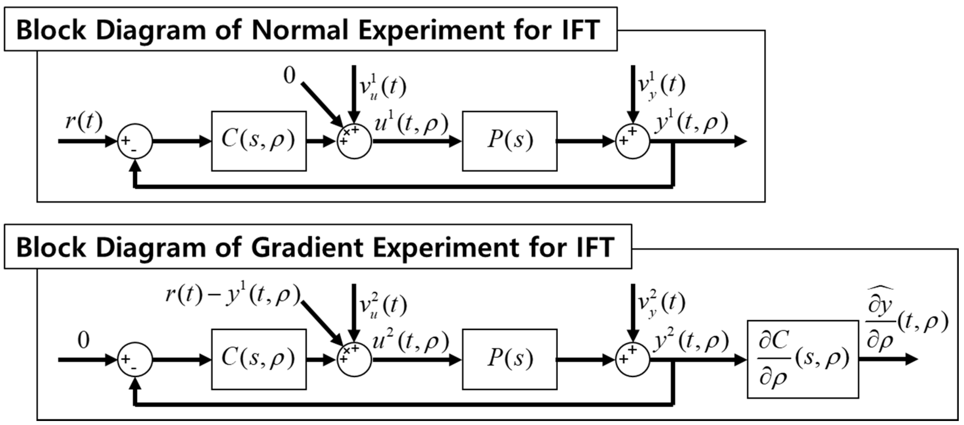
During IFT process, normal experiment and gradient experiment should be conducted sequentially, as shown in Figure 3, at every iteration, and through this, update of gain values to minimize the evaluation function can be performed.
It is necessary to select a reference filter to generate a desired response waveform for each degree of freedom. For the horizontal position, the secondary vibration system step response with a natural frequency of 10 Hz and a damping factor of 0.8 was selected. For roll and pitch attitude, the natural frequency of the reference filter was changed to 20 Hz to have a faster response speed. Due to the MSBS electromagnet arrangement used in this study, the magnetic constraint force and moment are relatively weak with respect to the vertical position and yaw attitude direction. Accordingly, the natural frequencies of the reference filter were selected as 5 and 3 Hz, respectively. Figure 4 shows the result of performing IFT for position and attitude control simulation of the MSBS. It can be seen that the response of the MSBS converges to the response of the reference filter through the five-update iterations.

3.2. Adaptive Control Scheme

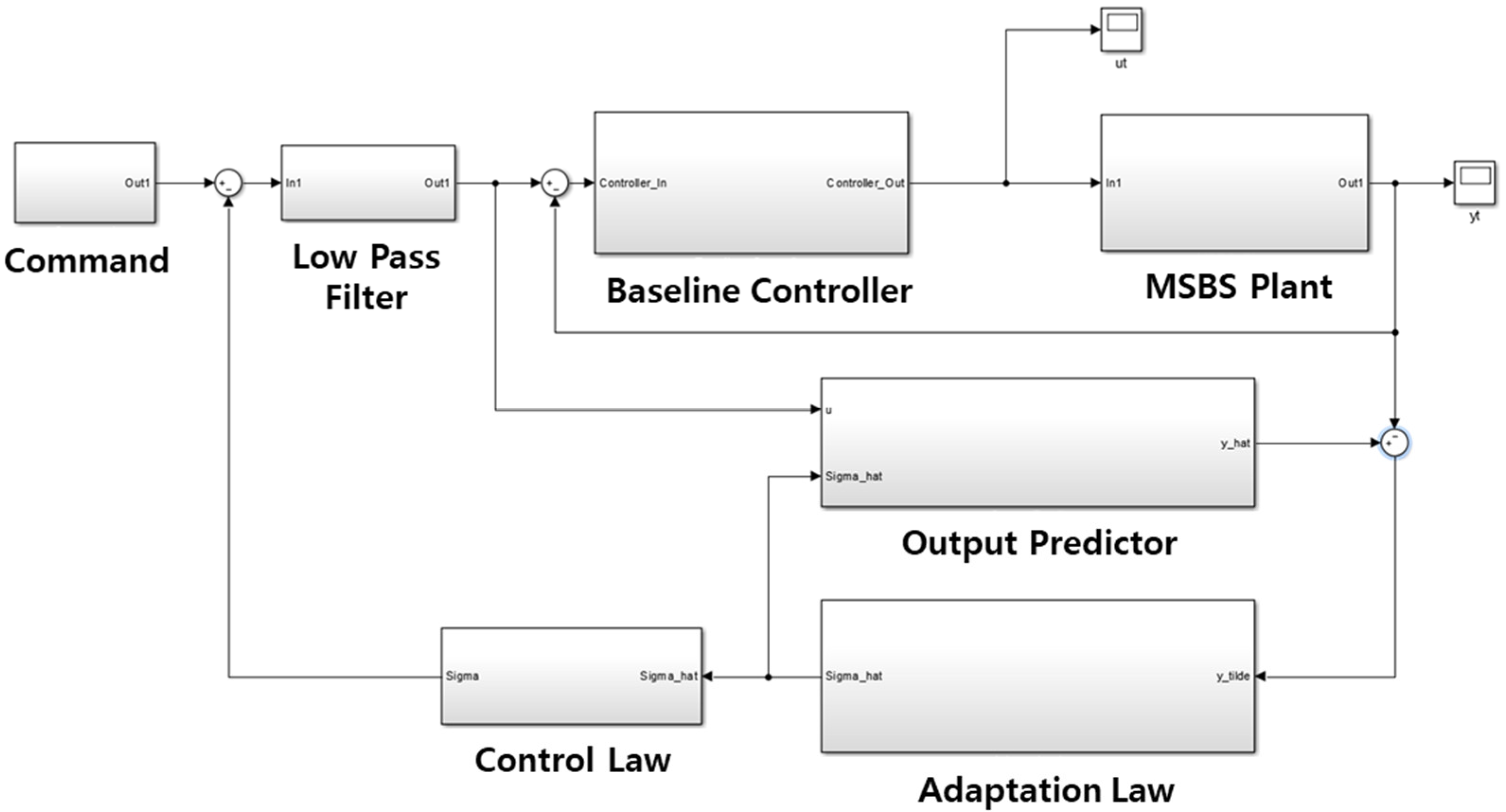
Adaptive control is a technique mainly applied to the problem of changing the operating environment or the system itself. In order to overcome the mathematical uncertainty that occurs during modeling of the system to be controlled, the structure or parameters of the control system are changed to satisfy the given performance requirements. However, high sampling frequency is required for parameter adaptation, and excessive control input can cause the actuator to saturate. L1 adaptive output feedback control does not require a model of the system to be controlled, and because it uses a low-pass filter, excessive control input is prevented and the system stability is good [27]. L1 adaptive output feedback controllers were constructed for each single input/output system using six independent PD controllers used in the existing MSBS simulator as baseline controllers, as shown in Figure 5.
The output predictor and low-pass filter can be selected using the linear system theory, but intuition based on experience is required to select the most suitable combination. When selecting an output predictor, the dynamic characteristics of the system to be controlled must be considered, and there is no intuitive lower limit when selecting the bandwidth of the low-pass filter, but the upper limit must not exceed the bandwidth of the actuator [28,29]. In this study, the reference filter used in IFT was used as the output predictor of each degree of freedom, and a primary vibration system with a natural frequency of 7 Hz and a damping factor of 0.8 was selected as the low-pass filter.

4. Position and Attitude Control Simulation with Power Supply Failure Condition

4.1. Electric Power Supply of MSBS

The magnitude of the magnetic force and moment generated by the MSBS is proportional to the magnitude of the electric current supplied to the electromagnet, and a current of the correct magnitude must be input to each electromagnet for precise position and attitude control. The MSBS presented in this study includes eight independent push-pull electric power supplies, in which two Darlington circuits are connected to a return-line current sensing circuit to accurately supply high current to each electromagnet. The electric circuit and the overall power supply are shown in Figure 6. Each channel of the power supply can generate up to ±10 A of electric current. The Darlington circuit has a very high current amplification rate at the output stage, and the output current can be precisely controlled through the return-line current sensing circuit. Power semiconductor devices, such as transistors used in the electric power supply, can be degraded by thermal effect due to power cycling overstress. In consequence, performance may gradually deteriorate over time, and then complete failure may occur at a specific moment [30]. If the correct current is not supplied to the MSBS electromagnet, the position and attitude of the test object, which is suspended in the air only depend on the magnetic field, can become unstable and a risk of a fall accident will rise. With classic control algorithms, it is difficult to maintain the initial control performance in such a situation where the system characteristics vary with time. However, when the adaptive control algorithm is applied, the change in position and attitude control performance can be minimized. In addition, even in the event of complete failure of the power supply, if there is sufficient amount of electromagnets that operate normally, secondary damage due to drop of the test object can be reduced through adaptive control allocation.

4.2. Harmonic Excitation Simulation with Power Supply Failure

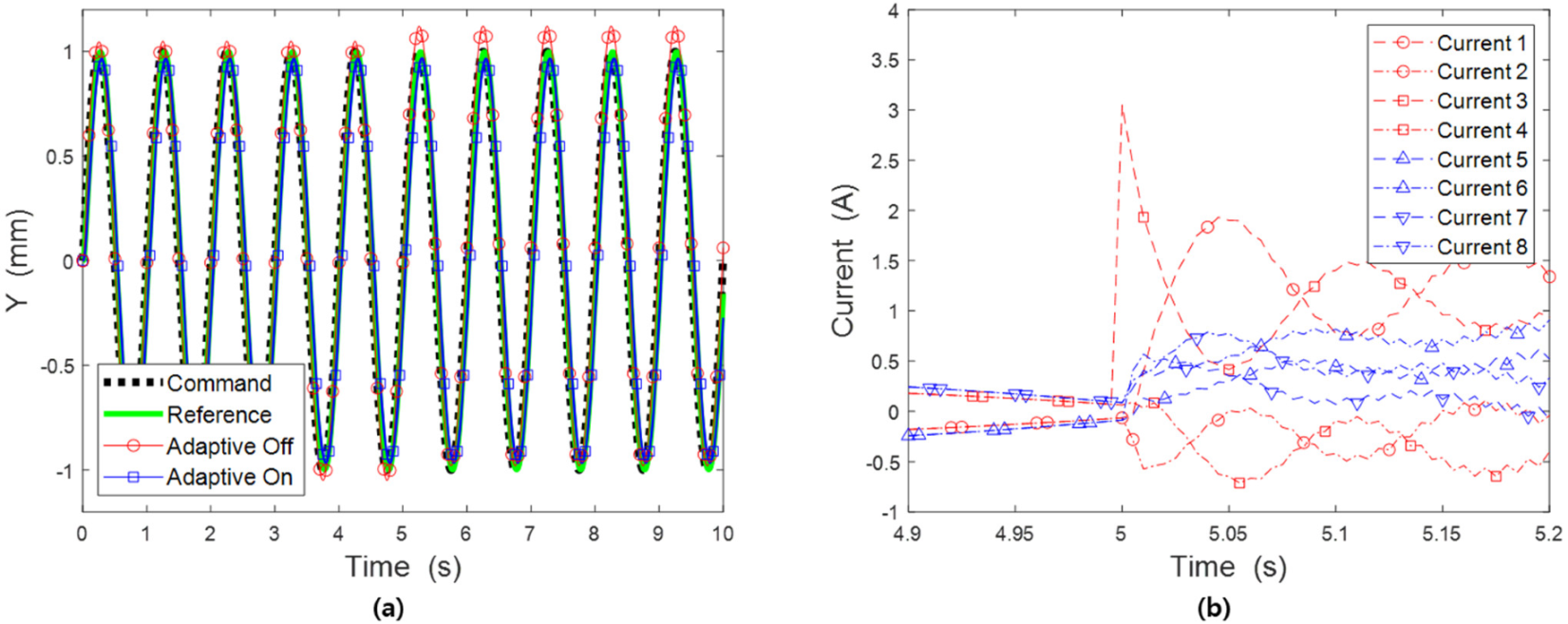
Assuming the vibration experiment was performed on a structure model exposed to aerodynamic loads in the test section of wind tunnel, simulations on control of position and attitude of the test object were performed, while a harmonic function was used as a control command. The calculations were carried out using Runge–Kutta fixed-step solver within MATLAB Simulink, and the time step was 5 ms. First, a simulation was performed for the case where the desired position in the side direction (Y), which is one of the positional degrees of freedom of the test object, was a sine wave having a frequency of 1 Hz, an amplitude of 1 mm, and the results are shown in Figure 7. Assuming a sudden performance degradation of the electric power supply, the amplification rate of the power supply for No. 3 electromagnet was reduced by 20%, and a bias current of 3 A was added from 5 s after the start of the simulation. During the initial 5 s of the simulation, it was observed that the command following performance did not differ significantly depending on whether the adaptive control algorithm was activated or not. However, it can be seen that from 5 s after the failure of the electric power supply, a noticeable difference occurs in the command following performance according to the application of the adaptive control algorithm.
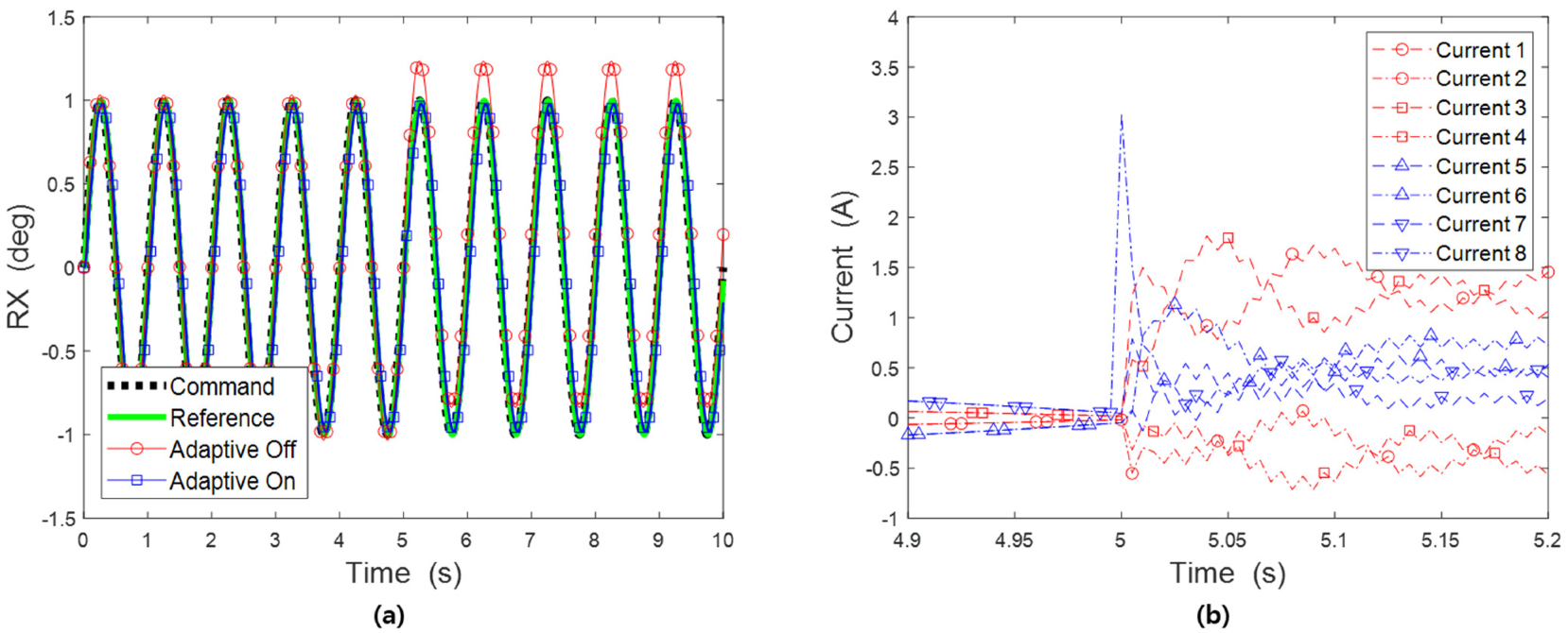
The next simulation was performed for the case where the desired attitude in the roll direction (RX), one of the rotational degrees of freedom of the test object, was a sine wave with a frequency of 1 Hz and an amplitude of 1 deg, and the results are shown in Figure 8. Similarly, the amplification rate of the power supply for the No. 8 electromagnet was reduced by 20% at 5 s after the start of the simulation, while a bias current of 3 A was added assuming a sudden performance degradation. As in the previous simulation, there is no significant difference in the command following performance before the failure of the power supply occurred. However, after the failure, it can be confirmed that the control system with adaptive algorithm shows better performance than the simple PD controller.
The MSBS with the electromagnet arrangement presented in this study generates the weakest constraint moment in the yaw direction of the test object. Therefore, the yaw direction can be predicted as the direction most likely to be out of control due to the failure of the electric power supply. It was examined whether robustness against failure of the electric power supply was secured by performing harmonic excitation simulation in the yaw direction of the test object. The simulation was performed using a sine function with a frequency of 1 Hz and a magnitude of 1 deg as the yaw attitude command. When 5 s have elapsed since the start of the simulation, the amplification rate of the No. 2 electric power supply was lowered by 20% and a bias current of 3 A was added, and the results are shown in Figure 9. It is confirmed that a current of about ±5 A is required for each electromagnet to perform harmonic excitation in the yaw direction before the current supply failure occurs. This is relatively large value when compared with the side (Y) directional and roll (RX) directional simulations. It can be, through this, confirmed again that the constraint moment in the yaw direction of the MSBS presented in this study is relatively very weak. Meanwhile, it is observed that the change in command following performance is not as large as expected after the failure of the electric power supply in the state where adaptive control is not applied. It can be inferred that this is because the magnitude of the bias current is not relatively large compared to the current used in the absence of failure. In addition, it shows almost constant level of command following performance regardless of current supply failure when adaptive control algorithm is applied. Based on these simulation results, when the adaptive control algorithm is applied to the MSBS position and attitude control system, it is expected that the test with the MSBS can be completed stably even if the current supply device fails.

4.3. Effect of Natural Frequency of Low Pass Filter

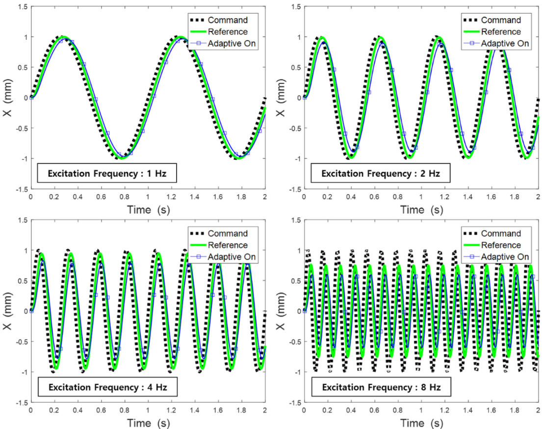
As described above, there is generally no intuitive lower bound when selecting the bandwidth of the low pass filter included in the L1 adaptive output feedback algorithm. In order to precisely perform the vibration test using MSBS, the bandwidth should be selected in consideration of the frequency of harmonic excitation input as a position and attitude control command. Figure 10 shows the simulation results according to the frequency change of harmonic excitation. In case of excitation with a frequency of 1 Hz, both the reference model, the secondary vibration system with a natural frequency of 10 Hz, and the MSBS follow the command well. However, it can be seen that the command following performance decreases as the frequency of harmonic excitation increases. In addition, the reason that the performance of MSBS is relatively lower than that of the reference model is because the upper bound of the bandwidth of the LPF included in the position and attitude control system of the MSBS is lower.
Harmonic excitation simulations with frequency of 8 Hz were performed to compare the command following performance according to the change in bandwidth of the low pass filter, and the results are shown in Figure 11. It was observed that the command following performance improved as the upper bound of the bandwidth was increased from 3 Hz, but it was confirmed that the performance was rather lowered at 11 Hz or higher. It is necessary to consider the actuator characteristics when selecting the upper bound of bandwidth of the low pass filter so that excessive response does not occur. The magnitudes of the electric currents, shown in Figure 11, indicate that the command following performance of the MSBS can be deteriorated as excessive control commands are saturated by the limitation of the electric power supply.

5. Conclusions

The magnetic levitation and balance system (MSBS) can fix a test object in the center of the test section without mechanical contact during the wind tunnel test, and the position and attitude can be precisely controlled and the external forces and moments can be measured. If this function of MSBS is fully utilized, it will be possible to conduct a vibration test on a structure in the wind tunnel test section without the influence of mechanical support. Since the test object is levitated in the air only depending on the magnetic field generated by the MSBS, the position and attitude control system must ensure high command-following performance and robustness against failure of components, such as electric power supply, in order to stably perform tests. In this study, the control gains of the baseline controllers of the MSBS were optimized using the iterative feedback tuning technique. In addition, several simulations were performed to confirm the robust command following performance against failure of the electric power supply by applying the L1 adaptive output feedback control algorithm. It was possible to secure robust control performance against failure of the electric power supply of the MSBS. However, it was confirmed that the command following performance decreased as the frequency of command increased due to the bandwidth of the low pass filter through harmonic excitation simulation. Additionally, performance degradation was observed due to occurrence of transient response when the upper bound of the bandwidth was increased. Therefore, in order to conduct a vibration test on a structure in an environment without mechanical contact using the MSBS, it is necessary to select an appropriate low pass filter in consideration of the experimental conditions and characteristics of the electric power supply. It is also necessary to analyze the performance change according to the output predictor of the adaptive algorithm.

Funding

This was supported by Korea National University of Transportation (KNUT) in 2021.

Institutional Review Board Statement

Not applicable.

Informed Consent Statement

Not applicable.

Data Availability Statement

Not applicable.

Acknowledgments

This was supported by Korea National University of Transportation Industry-Academy Cooperation Foundation in 2021. (No. 202102280001).

Conflicts of Interest

The authors declare no conflict of interest.

References

  1. Sawada, H.; Umezawa, K.; Yokozeki, T.; Watanabe, A.; Otsu, T. Wind tunnel test of Japanese arrows with the JAXA 60-cm magnetic suspension and balance system. Exp. Fluids 2012, 53, 451–466. [Google Scholar] [CrossRef]
  2. Schoenenberger, M.; Cox, D.E.; Schott, T.; Mackenzie, A.; Ramirez, O.; Britcher, C.P.; Neill, C.; Wienmann, M.; Johnson, D. Preliminary Aerodynamic Measurements from a Magnetic Suspension and Balance System in a Low-Speed Wind Tunnel. In Proceedings of the Applied Aerodynamics Conference, Atlanta, GA, USA, 25–29 June 2018; p. 3323. [Google Scholar]
  3. Kai, D.; Sugiura, H.; Tezuka, A. Magnetic Suspension and Balance System for High-Subsonic Wind Tunnel. AIAA J. 2019, 57, 2489–2495. [Google Scholar] [CrossRef]
  4. Kaymak, Z. A Simulation of Magnetic Suspension and Balance System for Wind Tunnel. Master’s Thesis, Pennsylvania State University, State College, PA, USA, 2018. [Google Scholar]
  5. Oshima, R.; Sawada, H.; Obayashi, S. A Development of Dynamic Wind Tunnel Testing Technique by Using a Magnetic Suspension and Balance System. In Proceedings of the 54th AIAA Aerospace Sciences Meeting, San Diego, CA, USA, 4–8 January 2016; p. 1541. [Google Scholar]
  6. Tuttle, M.H.; Moore, D.L.; Kilgore, R.A. Magnetic Suspension and Balance System; A Comprehensive, Annotated Bibliography; National Aeronautics and Space Administration: Washington, DC, USA, 1991. [Google Scholar]
  7. Sawada, H.; Tetsuya, K. Development of a 60 cm Magnetic Suspension System. Jpn. Soc. Aeronaut. Space Sci. 2002, 50, 188–195. [Google Scholar]
  8. Sawada, H.; Suenaga, H.; Kunimasu, T.; Kohno, T. Status of MSBS Study at NAL in 1995. In Proceedings of the Third International Symposium on Magnetic Suspension Technology, Tallahassee, FL, USA, 13–15 December 1995; pp. 505–519. [Google Scholar]
  9. Sawada, H.; Kohno, T.; Kunimasu, T. Status of MSBS Study at NAL. In Proceedings of the Fifth International Symposium on Magnetic Suspension Technology, Santa Barbara, CA, USA, 1–3 December 1999; pp. 659–674. [Google Scholar]
  10. Oh, J. Development of a 6-Axes Control Magnetic Suspension and Balance System for the Wind Tunnel Experiments. Master’s Thesis, Fukuoka Institute of Technology, Fukuoka, Japan, 2004. [Google Scholar]
  11. Covert, E.E. Magnetic Suspension and Balance Systems. IEEE Aerosp. Electron. Syst. Mag. 1988, 3, 14–22. [Google Scholar] [CrossRef]
  12. Vlajinac, M.; Covert, E.E. Sting-free measurements of sphere drag in laminar flow. J. Fluid. Mech. 1972, 54, 385–392. [Google Scholar] [CrossRef]
  13. Dress, D.A. Drag measurements on a Modified Prolate Spheroid Using a magnetic Suspension and Balance System. J. Aircr. 1990, 27, 523–528. [Google Scholar] [CrossRef]
  14. Britcher, C.P.; Alcorn, C.W. Interference-free measurements of the subsonic aerodynamics of slanted-base ogive cylinders. AIAA J. 1991, 29, 520–525. [Google Scholar] [CrossRef]
  15. Britcher, C.P. Application of Magnetic Suspension and Balance Systems to Ultra-High Reynolds Number Facilities; Flow at Ultra-High Reynolds and Rayleigh Numbers; Springer: New York, NY, USA, 1998. [Google Scholar]
  16. Britcher, C.P.; Ghofrani, M. A magnetic suspension system with a large angular range. Rev. Sci. Instrum. 1993, 64, 1910–1917. [Google Scholar] [CrossRef] [Green Version]
  17. Groom, N.J.; Britcher, C.P. A description of a laboratory model magnetic suspension test fixture with large angular capability. In Proceedings of the The First IEEE Conference on Control Applications, Dayton, OH, USA, 13–16 September 1992; pp. 454–459. [Google Scholar]
  18. Sawada, H.; Kunimasu, T.; Suda, S. Sphere Drag Measurements with the NAL 60 cm MSBS. J. Wind Eng. 2004, 98, 129–136. [Google Scholar]
  19. Higuchi, H.; Van Langen, P.; Sawada, H.; Tinney, C.E. Axial flow over a blunt circular cylinder with and without shear layer reattachment. J. Fluids Struct. 2006, 22, 949–959. [Google Scholar] [CrossRef]
  20. Higuchi, H.; Sawada, H.; Kato, H. Sting-free measurements on a magnetically supported right circular cylinder aligned with the free stream. J. Fluid Mech. 2008, 596, 49–52. [Google Scholar] [CrossRef]
  21. Shinji, K.; Nagaike, H.; Nonomura, T.; Asai, K.; Okuizumi, H.; Konishi, Y.; Sawada, H. Aerodynamic characteristics of low-fineness-ratio freestream-aligned cylinders with magnetic suspension and balance system. AIAA J. 2020, 58, 3711–3714. [Google Scholar] [CrossRef]
  22. Kawamura, Y.; Takenaga, T.; Oh, J. Development of a low electric power 40 cm class magnetic suspension and balance system. J. Wind Eng. 2004, 98, 117–127. [Google Scholar] [CrossRef] [Green Version]
  23. Lee, D.K.; Han, J.H. Safety-Guaranteed Flight Test Environment for Micro Air Vehicles. AIAA J. 2016, 54, 1018–1029. [Google Scholar] [CrossRef]
  24. Reitz, J.R.; Milford, F.J.; Christy, R.W. Foundations of Electromagnetic Theory; Addison-Wesley Pub. Co.: Boston, MA, USA, 1993. [Google Scholar]
  25. Hjalmarsson, H. Iterative Feedback Tuning-an Overview. Int. J. Adapt. Control. Signal Process. 2002, 16, 373–395. [Google Scholar] [CrossRef]
  26. Huusom, J.K. Improving Convergence of Iterative Feedback Tuning. J. Process. Control. 2009, 19, 570–578. [Google Scholar] [CrossRef] [Green Version]
  27. Jung, Y.; Shim, D.H. Design the Flight Control System against Model Uncertainty. In Proceedings of the KSAS Fall Conference, Jeju, Korea, 15–16 November 2012; pp. 551–556. [Google Scholar]
  28. Hovakimyan, N.; Cao, C. L1 Adaptive Control Theory; SIAM: Philadelphia, PA, USA, 2010. [Google Scholar]
  29. Michini, B.; How, J.P. L1 Adaptive Control for Indoor Autonomous Vehicles: Design Process and Flight Testing. In Proceedings of the AIAA Guidance, Navigation, and Control Conference, Chicago, IL, USA, 10–13 August 2009; p. 5754. [Google Scholar]
  30. Celaya, J.R.; Saxena, A.; Kulkarni, C.S.; Saha, S.; Goebel, K. Prognostics approach for power MOSFET under thermal-stress aging. In Proceedings of the Annual Reliability and Maintainability Symposium, Reno, NV, USA, 23–26 January 2012; pp. 1–6. [Google Scholar]
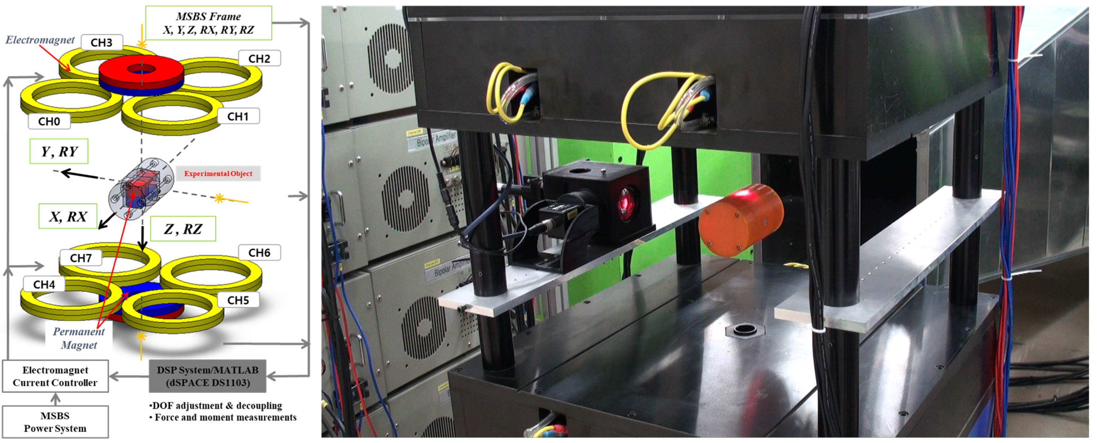
Figure 1. Configuration of the 30 × 30 cm magnetic suspension and balance system for the wind tunnel.
Aerospace 08 00304 g001
Figure 2. Position and attitude control system and control strategy of the MSBS.
Aerospace 08 00304 g002
Figure 3. Block diagrams of normal and gradient experiment for iterative feedback tuning.
Aerospace 08 00304 g003
Figure 4. Step responses of the test object with respect to the number of iteration.
Aerospace 08 00304 g004
Figure 5. Block diagram for position and attitude control simulation of the MSBS with L1 adaptive output feedback control scheme.
Aerospace 08 00304 g005
Figure 6. Electric circuit of a single push–pull power supply for an electromagnet.
Aerospace 08 00304 g006
Figure 7. Harmonic excitation simulation with reduced amplification rate (80%) and bias current (3 A) on No. 3 push–pull power supply: (a) Harmonic response of the test object in side (Y) direction; (b) electric currents for each electromagnet.
Aerospace 08 00304 g007
Figure 8. Harmonic excitation simulation with reduced amplification rate (80%) and bias current (3 A) on No. 8 push–pull power supply: (a) Harmonic response of the test object in roll (RY) direction; (b) electric currents for each electromagnet.
Aerospace 08 00304 g008
Figure 9. Harmonic excitation simulation with reduced amplification rate (80%) and bias current (3 A) on No. 2 push–pull power supply: (a) Harmonic response of the test object in yaw (RZ) direction; (b) electric currents for each electromagnet.
Aerospace 08 00304 g009
Figure 10. X–position during harmonic excitation simulation of the MSBS for various excitation frequencies.
Aerospace 08 00304 g010
Figure 11. X–position and electric currents during harmonic excitation simulation of the MSBS for various bandwidth of low pass filter.
Aerospace 08 00304 g011
Publisher’s Note: MDPI stays neutral with regard to jurisdictional claims in published maps and institutional affiliations.