Review

The Progress of Aerodynamic Mechanisms Based on Avian Leading-Edge Alula and Future Study Recommendations

1
School of Aeronautics, Northwestern Polytechnical University, Xi’an 710072, China
2
Research & Development Institute, Northwestern Polytechnical University, Shenzhen 518057, China
3
Yangtze River Delta Research Institute, Northwestern Polytechnical University, Taicang 215400, China
*
Author to whom correspondence should be addressed.
Aerospace 2021, 8(10), 295; https://doi.org/10.3390/aerospace8100295
Submission received: 20 August 2021 / Revised: 8 October 2021 / Accepted: 9 October 2021 / Published: 13 October 2021
(This article belongs to the Section Aeronautics)

Abstract

:
Birds in nature have many unique devices to help them acquire excellent flight abilities under various complex flight conditions. One of the unique devices is the leading-edge alula, located at the junction of the arm wing and the hand wing of most birds. It often spreads out during takeoff and landing, probably playing a similar role to high-lift devices in fixed-wing aircraft. This paper analyzed and reviewed the results of current research on leading-edge alula, finding some important factors, such as the complex flapping motions, flexibility, and the plane and section shape of the wing, that have been ignored in current research to a certain extent. These would greatly affect the conclusions obtained. Hence, for a deeper understanding of the aerodynamic mechanisms and functions of the alula, some new study predictions for future research are presented. In addition, the feasible models and methods for further research based on these predictions are discussed and proposed. For example, the higher-accuracy LES or hybrid LES/RANS method and the combinations of these methods with wind-tunnel experiments using PIV technology are recommended.

1. Introduction

Flying creatures in nature have evolved for millions of years, with excellent flight ability and environmental adaptability. Unlike fixed-wing aircraft, birds often achieve stable flight even in complicated flight conditions by altering their whole body, including wings and tails [1]. For example, in takeoff and landing, maneuvering and low-altitude preying birds need more lift to support weight and attitude controllability to stabilize flight. During the evolution of birds over millions of years, their wings have formed some unique features and skeletal structures, which are of great help to their flight performance. The leading edge of the avian wing has evolved a unique winglet structure, called the alula, as shown in Figure 1. It is located at the junction of the arm wing and the hand wing of birds, and it consists of a digit bone and 2–6 feathers [1]. The alula is a very important aerodynamic device used by birds to improve their flight ability. During takeoff and landing, due to the low speed of birds, it is necessary for them to increase the angle of attack (AoA) to increase lift in order to balance gravity. However, with the increase in AoA, there is a risk of stalling, which is of great danger to flight. At this time, birds often deflect their alula, playing a role similar to high-lift devices in fixed-wing aircraft [2].
This paper includes two major sections: one evaluates the current research on the function of the alula, and the other predicts studies for future research on the alula. Firstly, the current research progress is analyzed, and comments on the current research are provided. In clarifying this progress, we found that some critical factors were neglected to a certain extent, such as the complex flapping motions, flexibility, and the plane and section shape of the wing. These probably had a great influence on the conclusions acquired. Secondly, some further aerodynamic mechanisms for future study were put forward. Furthermore, on the basis of the study predictions, feasible research models and methods were discussed. Through these analyses and discussions, on the one hand, the progress in current research on the alula can be clarified. On the other hand, this paper can provide guidance for further research on the alula, ultimately providing a better understanding of natural creatures.

2. Evaluation of the Current Research

In this section, we first summarize current research on the alula, including its aerodynamic mechanism, bionic application, deployment mode, and morphological measurements and statistics. Then comments and analysis of current research on the alula are given, including comments on models and methods in current alula research.

2.1. Review of Studies on the Alula

2.1.1. Aerodynamic Mechanism of the Alula

The initial research and discussion on the alula in academia can be traced back to the 1970s [3]. In recent years, with the increasing interest in bionic technology, research on the alula has gradually increased [4,5,6,7,8,9,10,11,12,13,14,15,16,17,18,19,20,21,22].
Through a summary and analysis of the current research, we can find that some pretty good insights have been gained from studies on the alula. Firstly, studies have found that the alula is mostly used by birds during takeoff and landing, playing the role of delaying flow separation and increasing lift, similar to high-lift devices in fixed-wing aircraft [1,2]. Secondly, there have been two main predictions regarding the aerodynamic mechanisms underlying the lift enhancement of the alula, which are the leading-edge slot effect [4,5] and the vortex generator effect [6].
Addressing the former, Meseguer et al. [4,5] built models of two-dimensional airfoils and three-dimensional wings with alulae by mimicking the geometric characteristics of the pigeon wing, and they investigated the effects of the alula on the aerodynamic characteristics at variable angles of attack using a wind-tunnel experiment. The experimental results for the two-dimensional airfoil showed that the alula has a function similar to the leading-edge slot. At high AoA, the deployed alula can delay flow separation and increase lift by reducing the reverse pressure gradient on the upper surface of the airfoil, as shown in Figure 2. Subsequently, the experimental results of the three-dimensional wing showed that the alula, with suitable geometric parameters, is a very effective high-lift device. Although its length is only 17.5% of the wingspan length, its maximum lift enhancement can be as high as 22%, as shown in Figure 3.
Another hypothetical mechanism of the alula is the vortex generator effect. By inducing downwash flow, the momentum in free inflow is injected into the boundary layer, which decreases the thickness of the shear layer on the upper surface of the wing and delays the flow separation. Lee et al. [6] used a wind tunnel to study the aerodynamic characteristics of static magpie wings with and without alulae. The results showed that the alula can increase the lift coefficient by 1.3–12.7% and delay stall by 5–10°, as shown in Figure 4. At the same time, the flow field measured using digital particle image velocimetry (DPIV) showed that, at high AoA, the streamwise vortices formed at the tip of the alula can induce a strong downwash flow on the upper surface of the wing, which can suppress flow separation and increase lift by transferring momentum from free inflow to the near-wall boundary layer at lower velocity, as shown in Figure 5.
A stable LEV can obviously increase the lift of flying creatures in nature, especially in insects, bats and small-scale birds [7,8,9,10,11,12]. For some specific flying creatures, a stably attached LEV can even enhance lift by 40% [9]. In some large-scale birds, LEV is still appearing during the flight. However, it is not as stable as that of insects and quickly transforms into flow separation [13]. Because of the unique position of the alula (located at the leading edge of the avian wing, at the junction of the hand wing and the arm wing), previous studies proposed a hypothesis for the effect of the alula on the LEV, whereby it can promote the LEV development of the hand wing [1]. Linehan and Mohseni [14,15] conducted wind-tunnel experiments on model alula. The PIV results showed that the alula is able to smoothly merge otherwise separated leading- and side-edge vortical flow, before maintaining the attached LEV on the wing. And it can stabilize a recirculatory aft-tilted LEV on a steadily translating unswept wing at post-stall angles of attack. Sander [16] studied the effect of the alula on a 3D flow structure during gliding and flapping flight by using numerical simulation. The results showed that a vortex formed at the leading-edge of the alula and interacts with the free shear layer formed behind the leading edge of the wing and induces low pressure thus increasing both lift and drag in the gliding flight. While there are negligible changes between the flow structure with and without the alula in the flapping flight, suggesting that the alula provides negligible benefit for flapping flight. However, it is not clear whether the alula has such an effect on the LEV and whether there are other factors of the alula affecting the LEV.

2.1.2. Bionic Application of the Alula

In the past 5 years, many leading-edge devices have been established by imitating the avian alula, and the influence of geometric parameters has been obtained.
Ge et al. [17] studied a 2D airfoil with a bionic leading-edge slot by imitating the avian alula. The results from a wind-tunnel experiment and numerical simulation showed that the bionic leading-edge slot can increase the stall angle and the maximum lift coefficient. Mandadzhiev et al. [18,19] investigated a 2D airfoil with a leading-edge alula device (LEAD) by mimicking the geometric characteristics of the alula, as shown in Figure 6. The effects of variable deflection angles and relative angles of attack of the LEAD were studied in the wind tunnel. The results showed that the LEAD mostly increases the lift at high AoA of the freestream (stall and post-stall cases). A larger deflection angle and a smaller relative angle of attack lead to greater lift, as shown in Figure 7. Following the studies of Mandadzhiev et al. [18,19], Ito et al. [20,21] conducted similar wind-tunnel experiments on the LEAD. They additionally studied the effects of variable distances between the LEAD and the wing root, namely, the spanwise LEAD location. The results showed that the lift generated by the wing–LEAD assembly is very sensitive to the spanwise location of the LEAD, and the maximum lift improvement can be achieved when the LEAD is placed near the semispan length of the wing. Meanwhile, the lift enhancement of the LEAD was higher in the 3D wing compared with the 2D airfoil. Linehan and Mohseni [22] used wind-tunnel experiments to study the effects of the alula-like leading-edge device on the aerodynamic characteristics in a fixed-wing MAV, as shown in Figure 8. The results showed that the alula only works within the limits of AoA, and the aerodynamic characteristics are greatly affected by the distance between the alula and the wing root, as shown in Figure 9. If a single alula or asymmetrically arranged alulae are used, roll can be controlled, with an efficiency one order of magnitude better than traditional flaps and ailerons, as shown in Figure 10. The alula could produce a maximum roll moment of 0.036, which is better than the control force of a −20° flap aileron [23,24,25]. Subsequently, Linehan et al. [26] constructed a sliding-alula wing (SAW) and carried out a wind-tunnel experiment. Then they designed a proportional-integral roll command-tracking controller. They found the SAW can successfully track +/− 15 deg doublet roll commands with less than 3 deg overshoot and a rise time of around 0.5 s while regulating wing-rock-induced roll oscillations to below 5 deg.

2.1.3. Deployment Mode of the Alula

Some researchers proposed that the deployment of the alula is caused by the aerodynamic force applied on the avian wings and the alula, and there is no active control from bird muscles in its deployment, i.e., a passive deflection mode [27]. Austin and Anderson [27] tested the static specimens of water duck wings using a wind tunnel. The results showed that the alula would unfold at a specific angle of attack and velocity combination, as shown in Figure 11. That is, for a given speed, the alula deploys at the smallest AoA. Along with the increase in AoA, the alula gradually opens to the maximum extent. Finally, as the AoA continues to increase, the alula gradually retracts to complete closure. Therefore, it was suggested that the role of the alula is more likely to reduce the risk of stall through a perception of aerodynamic forces. Because the experiment used specimens, it was implied that the deployment of the alula is passively caused by the aerodynamic force.
However, some studies suggest that the deployment of the alula is actively controlled by the muscles of birds, i.e., an active deflection mode [6]. Lee et al. [6] found that the alula unfolds when the flight speed is very low and the aerodynamic force is too small to support the deflection of the alula at this low speed; therefore, they suggested that the alula deflects under the active control of bird muscles. Furthermore, some investigations suggested that the deployment of the alula includes both the passive deflection mode caused by aerodynamic forces and the active deflection mode controlled by avian muscles. These two deflection modes are integrated during variable flight stages [28]. Carruthers et al. [28] trained a steppe eagle and conducted outdoor flight experiments; they then captured pictures of the alula and other special feathers of the steppe eagle at distinct flight stages using high-speed cameras. During landing, they found that the deflection mode of the alula would change from an initial passive deflection mode to an active control mode. However, the deployment mechanism of the alula is still a matter of debate as it is not exactly clear via which mechanism birds deploy their alula.

2.1.4. Morphological Measurements and Statistics of the Alula

There are several studies on the morphology of the alula. The wing platform of the avian wing can be systematically divided into four categories [29,30] (as shown in Figure 12): (a) elliptical wing, with a low aspect ratio and a uniform pressure distribution, can provide good maneuverability. Typical birds: peckers, hornbills, grouses and woodcocks. (b) high speed wing, with low camber airfoils, moderate high aspect ratio and pronounced sweepback of the leading-edge, can sustain high-speed flight. Typical birds: swifts, hummingbirds and swallows. (c) high aspect ratio wing, with large aspect ratio, can help birds soar over water surface with high aerodynamic efficiency. Typical birds: albatrosses, gannets and gulls. (d) high lift wing, with slotted wing tip, moderate aspect ratio and pronounced camber airfoils, can fly efficiently at low speed. Typical birds: eagles, owls, harriers, ravens and pelicans. Alvarez et al. [31] measured several parameters of the wing geometry of almost four hundred and fifty birds. They found all type (a) wings have the alula placed at distances from the wing root ranging from 0.25–0.3 times the wing span, whereas type (b) wings have smaller such distances and type(c)(d) wings have larger distances. Also their results showed that the ratio of the length of the alula to the wing span decreases with the increasing aspect ratio of the wing. Lee and Choi [2] investigated the relationship between the size and shape of the alula and the features of the wing in the Laridae and Sternidae. They found that for Laridae, the aspect ratio of the alula was smaller in the species that have relatively longer wings, but the pattern was opposite in the Sternidae, suggesting the species with high loading potential and long wings exhibit long alula. Linehan and Mohseni [15] measured the alula’s spanwise position on spread-wing specimens. They found that the relationship between the spanwise location of the alula d(the distance of the alula’s root from the wing tip) and the length of the spread wing Lw can be well analyzed using an empirical scaling formula d = k L w α , where α is the allometric exponent and k is the allometric coefficient.

2.2. Comments and Analysis of Current Alula Research

Although current research on the alula is a good achievement, limited by research methods and research models, the authors believe that there is still more research to be done.

2.2.1. Comments on Research Models

Current researches often greatly simplify the real model, but these simplifications may affect the judgment of the conclusion, to some extent.
(1).
The unsteady effect of the complex flapping motions is not involved.
To the best of our knowledge, the literature of the alula available at present most adopt static, steady models, whether in wind tunnel experiments or numerical simulations. That is, they do not consider the effects of the complex flapping motions in the real avian flight. However, the flapping motions of birds are very strong during the taking-off and landing (in which the alula plays an important role) [33]. At the same time, many researchers have pointed out that the flapping modes and kinematics of the avian wing is very important to the high-lift and large-thrust during the flight of birds. The typical flapping modes can be divided into four categories: plunge, twist, sweep and fold [33,34,35,36]. Plunging motion is the core mode. In the beginning, researchers revealed the reason birds can produce thrust using a plunging airfoil [37,38]. Subsequently, Ashraf et al. [39] systematically investigated the influence of different plunge parameters on thrust and thrust efficiency. They found the thrust and thrust efficiency increases with the increasing frequency. And the flow structure becomes chaotic as the plunging amplitude increases. Young [40,41] found the thrust efficiency obtains the maximum value when Strouhal number (St) ranges in 0.1–0.4. More details of plunging motion can be found in reference [42]. Twisting motion can also produce thrust. With the increasing twisting amplitude, time-averaged thrust increases, whereas thrust efficiency decreases [43]. Yu et al. [44] found that combining plunging motion and twisting motion will improve thrust performance. And the thrust efficiency peaks when the phase difference between plunging and twisting motion is 90 deg [45]. A sweeping motion will also help birds improve thrust and thrust efficiency [46]. During the downstroke of birds’ slow flight, a forward sweeping motion will also increase the lift [47]. Folding motion will cause the change of wingspan. Wang et al. [48] found that folding motion will increase both the time-averaged lift coefficient and instantaneous lift coefficient. Further research [49,50] revealed that folding motion can also increase the efficiency of lift production and reduce power consumption. Therefore, it may be inadequate to conduct the studies only under static and steady conditions. It is more advantageous to reveal the true aerodynamic mechanisms of the alula after considering the complex flapping motions.
(2).
The influence of elastic deformation caused by flexibility is not involved.
At present, most models adopted in the previous literature are rigid structures, which do not consider the effect of elastic deformation caused by the flexibility of wings. Many studies have proved that flexibility has a significant impact on the thrust, lift and power consumption [51]. Shyy et al. [52] comprehensively overviewed the progress in flapping wing aeroelasticity. Here, we introduce some typical researches. Heathcote et al. [53,54] investigated the influence of flexibility on the thrust using water-tunnel experiments. They found that proper chordwise flexibility can improve thrust coefficient and thrust efficiency [53]. The thrust efficiency gets the maximum when the flexible deformation phase ranges from 95 deg to 100 deg. Meanwhile, proper spanwise flexibility can also improve thrust efficiency, while high spanwise flexibility will damage the thrust [54]. Kang et al. [55] investigated the effect of chordwise and spanwise flexibility on the thrust efficiency using the CFD/CSD coupling method. They found that the wing obtains maximum thrust when it flaps with a flapping frequency near its resonance frequency, whereas the maximum thrust efficiency corresponds to half of the first-order natural frequency. So ignoring the flexibility of the research models also has a negative impact on the accuracy of conclusions.
(3).
The influence of the real avian wing plane and section shape is not involved.
In the current research, the plane shape of the wing is basically simplified to a rectangular wing [18,19,20,21,22]. However, the influence of the plane and section shape on the aerodynamic characteristics is an important factor. Wing plane shape includes wing area, aspect ratio, sweep angle, etc. Wing section shape includes chamber and thickness of the airfoil. These all have significant impacts on the aerodynamic force. Gong et al. [56] investigated the influence of wing shape, aspect ratio on the thrust performance using numerical simulation. They found that the thrust performance of flapping wing firstly increases then decreases with the increasing aspect ratio. Thielicke et al. [57] studied the impact of chamber and thickness of bird-like airfoil on LEV and lift using wind-tunnel experiments. The results showed that both large chamber and small thickness can increase the lift. The large chamber enhances the lift by increasing the bound circulation, while small thickness enhances the lift by promoting LEV formation. Subsequently, Thielicke et al. [58] further investigated the influence of local twist angle of airfoil on the lift and lift efficiency. They found that a negative twist of the airfoil during the downstroke will decrease the lift by suppressing LEV. But this twist can increase the lift efficiency by reducing the power consumption due to vortex shedding. Thus, it is necessary to consider the plane shape and section shape of real birds.

2.2.2. Comments on Research Methods

At present, the methods adopted in current research are usually wind-tunnel experiments and numerical simulations (mainly computational fluid dynamics (CFD)). These two methods have their own advantages. For example, wind-tunnel experiment can reflect the real physical essence and flow field with high accuracy, while numerical simulations can save resources compared with wind-tunnel experiments. However, there are also some limitations when applied to studies on the aerodynamic mechanisms of the alula.
Although wind-tunnel experiments can better reveal the real physical essence, its flow-field visualization has certain limitations. For example, traditional flow visualization methods, such as velvet and oil flow, can only obtain the flow structure on the wing surface, but cannot acquire the flow structure in the wake and far from the wing surface [59]. Advanced particle image velocimetry (PIV) technology can be used to measure the velocity in the wake and far from the wing surface, as well as the entire flow field [60,61]. However, PIV technology is limited by tracer particles and a complicated data processing process. There is some information loss during data processing. In particular, when the fluid has strong acceleration, the tracer particles cannot reflect the real movement of the fluid, thus affecting the authenticity of flow-field visualization [62,63]. However, in order to obtain the detailed aerodynamic mechanisms of the alula, a comprehensive and detailed analysis of the flow structure is indispensable.
On the other hand, numerical simulations can show three-dimensional flow structures in the whole flow field. The Reynolds-averaged Navier–Stokes (RANS) method with various turbulence models is widely used. However, it has strong limitations in simulating large separation and stall conditions [64,65]. Its accuracy is likely substantially inferior to wind-tunnel experiments when considering large separation and stall. Therefore, to better simulate alula mechanisms in large separation and stall conditions, it is necessary to use more accurate turbulence simulation methods, such as large eddy simulation (LES) or the hybrid LES/RANS method [65].

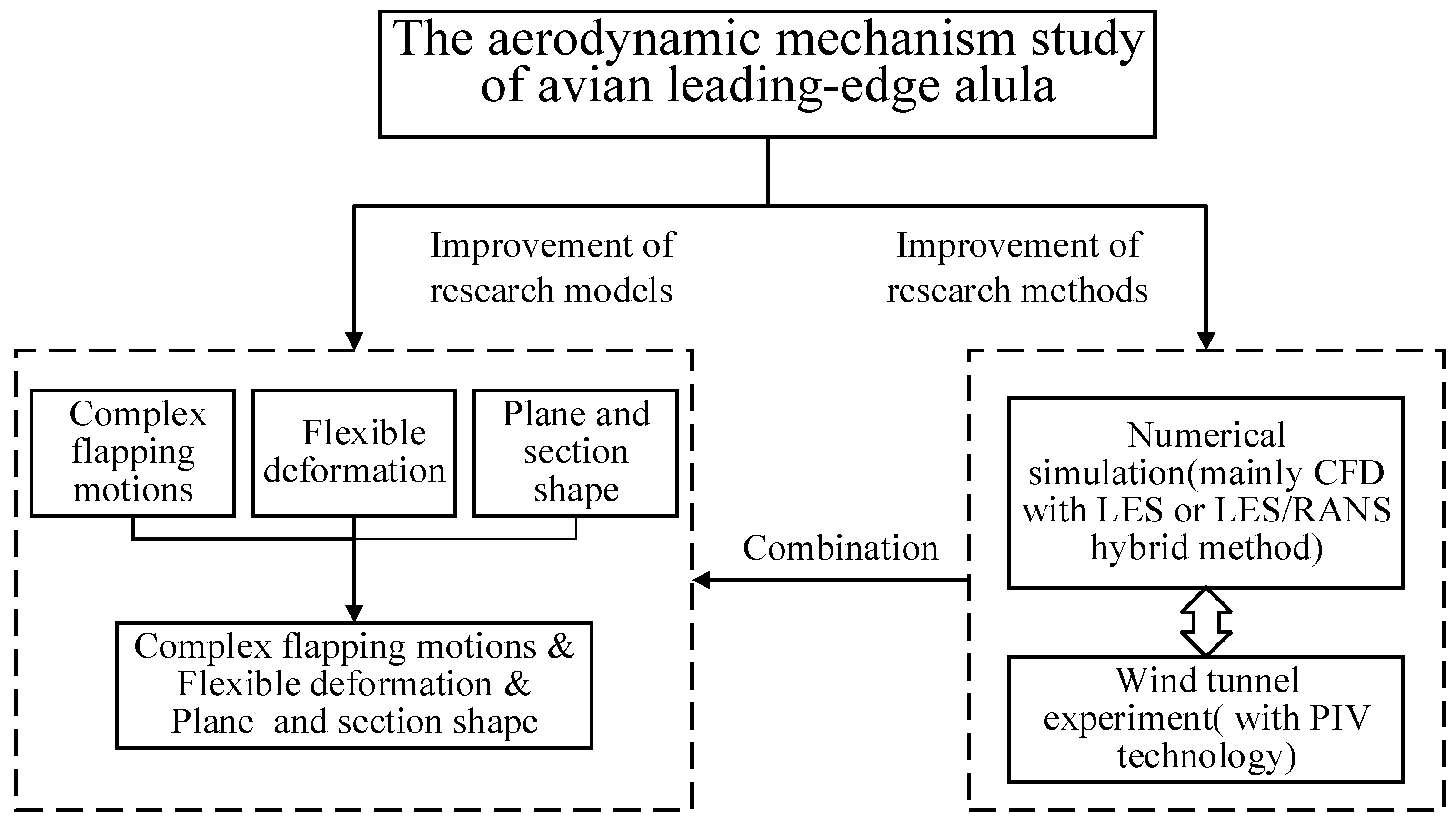
3. Study Predictions and Strategies for Future Research

Taking into account the above analyses of current research on the alula in Section 2, some study predictions for future research are presented involving an improvement of the research models and methods. Whereas these approaches may not yield insight into additional functions of the alula, the deeper aerodynamic mechanisms of the alula can be understood.
Thus, a detailed strategy for improving the research models is proposed. Lastly, according to these suggested improvements, optimal methods for studying the alula are recommended. This process is schematically presented in Figure 13.
We think that the aerodynamic mechanisms of the avian leading-edge alula should be further studied by improving the research models and methods. The detailed strategies for improvements are as follows:
Firstly, the aerodynamic mechanisms of the alula during complex rigid flapping motions and considering the flexible deformation of wings should be studied separately and then concurrently. Secondly, the influence of the wing plane and section shape of avian wings should be included to comprehensively evaluate the wing in a manner that is closest to nature.
To investigate the aerodynamic mechanisms of the three-dimensional alula, two projects are suggested. On the one hand, the aerodynamic mechanisms of a real bird wing with an alula need to be studied. According to the literature and the geometric data from observing birds in vivo, a natural wing model with an alula (imitating the wing plane shape and the cross-section shape of the bird) can be established. Then, according to the literature and the kinematic data from observing birds, the takeoff and landing kinematics of birds can be extracted. Next, the unsteady flow field and aerodynamic characteristics can be acquired by applying the kinematics of takeoff and landing to the established wing model. The aerodynamic mechanisms of the leading-edge alula can be obtained through an in-depth analysis of the flow-field structure.
On the other hand, an appropriately simplified model is necessary to study the aerodynamic mechanisms of the alula.
Firstly, the variable geometric parameters of a simplified model wing with an alula should be studied. The parameters to be studied include the alula length, the alula height, the alula width, the angle according to the three coordinate axes, the distance between the alula and wing roots, and the distance between the alula and the leading edge.
Then, the effect of kinematic modes and motion parameters should be investigated. The most typical three-dimensional flapping modes of birds include plunging, twisting, sweeping, and folding. The flight of birds in nature often combines these four modes of motion, whereby the most important is the plunging motion. Thus, using the plunging motion as the core, researchers should couple the other motion modes and study the effect of the motion parameters. Furthermore, the alula mostly plays a role during takeoff and landing, during which the twisting motion is probably not apparent. Thus, it can be ignored when studying the aerodynamic mechanisms of the alula. The suggested motion modes are as follows:
(1).
Pure plunging motion (plunging amplitude, frequency),
(2).
Plunging and sweeping (plunging amplitude, sweeping amplitude, frequency, phase difference),
(3).
Plunging and folding (plunging amplitude, folding amplitude, frequency, phase difference),
(4).
Plunging, sweeping, and folding (amplitudes, frequency, phase difference).
If researchers are aiming to investigate the effect of the alula during maneuvering, preying, or other flight modes, the twisting motion can also be taken into account.
Lastly, the combined influence of complex rigid flapping motions, flexible deformation of the wing, and wing plane shape and section shape needs to be evaluated.
Taking into account the results from the above-proposed studies, the effects of flexibility and wing plane shape and section shape should be studied using three-dimensional models.
As mentioned above in Section 2.2.2, the LES method or hybrid LES/RANS method, as well as their combination with wind-tunnel experiments using PIV technology, is suggested in future research.

4. Summary

This paper briefly reviewed the research progress on the leading-edge alula of birds, focusing on its aerodynamic mechanisms and applications. Generally speaking, there have been considerable achievements in research on the leading-edge alula. Its functions and aerodynamic mechanisms have been explained to a certain extent. Some exploratory studies have also been conducted, and the influences of variable parameters have been obtained. However, the current research ignored some important factors, which may have greatly influenced the conclusions obtained, such as complex flapping motions, flexibility, and the plane and section shape of the wing. For a deeper understanding of the aerodynamic mechanisms and functions of the alula, we suggest that more in-depth studies should be conducted considering the following aspects:
(1).
The plunging, sweeping, twisting, and folding motions of birds can produce very complex unsteady effects on the function of the alula. Thus, it is necessary to investigate the aerodynamic mechanisms of the alula during complex flapping motions.
(2).
Flexible deformation and wing plane and section shape have a significant impact on the aerodynamic characteristics of flying creatures and may cause special aerodynamic phenomena. Thus, it is necessary to study the aerodynamic mechanisms of the alula taking these factors into account.
(3).
Flying creatures in nature have complex flapping motions, different flexible deformations, and distinct wing plane shapes and section shapes. Therefore, research on the alula simultaneously considering all aspects can best reflect the aerodynamic mechanisms of the alula observed in nature.
Following a comprehensive consideration of accuracy and cost, the LES method or hybrid LES/RANS method, as well as their combination with wind-tunnel experiments using PIV technology, is suggested.

Author Contributions

Conceptualization, H.B. and B.S.; methodology, H.B.; formal analysis, W.Y.; investigation, J.X.; resources, H.B.; data curation, D.X.; writing—original draft preparation, H.B.; writing—review and editing, H.B. and B.S.; visualization, D.X.; funding acquisition, W.Y. All authors have read and agreed to the published version of the manuscript.

Funding

This work was supported in part by the National Key Research and Development Program of China under Grant 2017YFB1300102 and the National Natural Science Foundation of China under Grant 11872314.

Institutional Review Board Statement

Not applicable.

Informed Consent Statement

Not applicable.

Data Availability Statement

The study does not report any data.

Conflicts of Interest

The authors declare no conflict of interest.
NomenclatureAbbreviations
C P Pressure coefficient, P / ( 0.5   ρ v 2 ) LEVLeading Edge Vortex
C L Lift coefficient, L / ( 0.5   ρ v 2 s ) DPIVDigital Particle Image Velocimetry
C D Drag coefficient, D / ( 0.5   ρ v 2 s ) PIVParticle Image Velocimetry
C M Pitch moment coefficient, M / ( 0.5   ρ v 2 s ) AoAAngle of Attack
C l Roll moment coefficient, l / ( 0.5   ρ v 2 s b ) LEADLeading Edge Alula Device
α Angle of attack (deg.)CFDComputational Fluid Dynamics
β Relative angle of attack of alula(deg.)CSDComputational Structural Dynamics
γ Deflection angle of alula (deg.)RANSReynolds-averaged Navier-Stokes
d Distance of the alula root from wing tipLESLarge Eddy Simulation
ρ Density of fluidsARAspect Ratio
v Freestream velocityStStrouhal number
s Wing area
b Wing span

References

  1. Videler, J.J. Avian Flight; Oxford University Press: New York, NY, USA, 2006. [Google Scholar]
  2. Lee, S.-I.; Choi, H. Characteristics of the alula in relation to wing and body size in the Laridae and Sternidae. Anim. Cells Syst. 2016, 21, 63–69. [Google Scholar] [CrossRef] [Green Version]
  3. Nachtigall, W.; Kempf, B. Vergleichende Untersuchungen zur flugbiologischen Funktion des Daumenfittichs (Alula spuria) bei Vögeln. Z. Vgl. Physiol. 1971, 71, 326–341. [Google Scholar] [CrossRef]
  4. Meseguer, J.; Alvarez, J.C.; Meseguer, E.; Perez, A. The Alula: A Leading Edge, High Lift Device of Birds; IDR/UPM, Universidad Politécnica de: Madrid, Spain, 2003. [Google Scholar]
  5. Meseguer, J.; Franchini, S.; Pérez-Grande, I.; Sanz, J.L. On the aerodynamics of leading-edge high-lift devices of avian wings. Proc. Inst. Mech. Eng. Part G J. Aerosp. Eng. 2005, 219, 63–68. [Google Scholar] [CrossRef]
  6. Lee, S.-I.; Kim, J.; Park, H.; Jabłoński, P.G.; Choi, H. The Function of the Alula in Avian Flight. Sci. Rep. 2015, 5, 9914. [Google Scholar] [CrossRef] [PubMed] [Green Version]
  7. Videler, J.J.; Stamhuis, E.J.; Povel, G.D. Leading-edge vortex lifts swifts. Science 2004, 306, 1960–1962. [Google Scholar] [CrossRef] [Green Version]
  8. Shyy, W.; Liu, H. Flapping Wings and Aerodynamic Lift: The Role of Leading-Edge Vortices. AIAA J. 2007, 45, 2817–2819. [Google Scholar] [CrossRef]
  9. Muijres, F.T.; Johansson, L.C.; Barfield, R.; Wolf, M.; Spedding, G.; Hedenstrom, A. Leading-edge vortex improves lift in slow-flying bats. Science 2008, 319, 1250–1253. [Google Scholar] [CrossRef]
  10. Lentink, D.; Dickson, W.B.; Van Leeuwen, J.L.; Dickinson, M.H. Leading-edge vortices elevate lift of autorotating plant seeds. Science 2009, 324, 1438–1440. [Google Scholar] [CrossRef] [Green Version]
  11. Muijres, F.T.; Johansson, L.C.; Hedenström, A. Leading edge vortex in a slow-flying passerine. Biol. Lett. 2012, 8, 554–557. [Google Scholar] [CrossRef] [Green Version]
  12. Eldredge, J.D.; Jones, A.R. Leading-edge vortices: Mechanics and modeling. Annu. Rev. Fluid Mech. 2019, 51, 75–104. [Google Scholar] [CrossRef]
  13. Hubel, T.Y.; Tropea, C. The importance of leading edge vortices under simplified flapping flight conditions at the size scale of birds. J. Exp. Biol. 2010, 213, 1930–1939. [Google Scholar] [CrossRef] [Green Version]
  14. Linehan, T.; Mohseni, K. On the maintenance of an attached leading-edge vortex via model bird alula. J. Fluid Mech. 2020, 897. [Google Scholar] [CrossRef]
  15. Linehan, T.; Mohseni, K. Scaling trends of bird’s alular feathers in connection to leading-edge vortex flow over hand-wing. Sci. Rep. 2020, 10, 1–14. [Google Scholar] [CrossRef]
  16. Sander, A. The Role of the Alula in Avian Flight and It’s Application to Small Aircraft: A Numerical Study. Master’s Thesis, University of Groningen, Groningen, The Netherlands, 2018. [Google Scholar]
  17. Ge, C.; Ren, L.; Liang, P.; Zhang, C.; Zhang, Z. High-Lift Effect of Bionic Slat Based on Owl Wing. J. Bionic Eng. 2013, 10, 456–463. [Google Scholar] [CrossRef]
  18. Mandadzhiev, B.A.; Lynch, M.K.; Chamorro, L.P.; Wissa, A.A. Alula-Inspired Leading Edge Device for Low Reynolds Number Flight. In Proceedings of the ASME 2016 Conference on Smart Materials, Adaptive Structures and Intelligent Systems, Stowe, VT, USA, 28–30 September 2016; V002T06A016-V002T06A016; American Society of Mechanical Engineers: New York, NY, USA, 2016. [Google Scholar]
  19. Mandadzhiev, B.; Lynch, M.; Chamorro Chavez, L.P.; Wissa, A.A. An Experimental Study of an Airfoil with a Bio-inspired Leading Edge Device at High Angles of Attack. Smart Mater. Struct. 2017, 26, 094008. [Google Scholar] [CrossRef]
  20. Ito, M.R.; Duan, C.; Chamorro, L.P.; Wisaa, A.A. A Leading-Edge Alula-Inspired Device (LEAD) for Stall Mitigation and Lift Enhancment for Low Reynolds Number Finite Wings. In Proceedings of the ASME 2018 Conference on Smart Materials, Adaptive Structures and Intelligent Systems, San Antonio, TX, USA, 10–12 September 2018; V002T06A011-V002T06A011; American Society of Mechanical Engineers: New York, NY, USA, 2018. [Google Scholar]
  21. Ito, M.R.; Duan, C.; Wissa, A.A. The function of the alula on engineered wings: A detailed experimental investigation of a bi-oinspired leading-edge device. Bioinspiration Biomim. 2019, 14, 056015. [Google Scholar] [CrossRef]
  22. Linehan, T.; Mohseni, K. Investigation of a sliding alula for control augmentation of lifting surfaces at high angles of attack. Aerosp. Sci. Technol. 2019, 87, 73–88. [Google Scholar] [CrossRef]
  23. Fischel, J.; Naeseth, R.L.; Hagerman, J.R.; O’Hare, W.M. Effect of Aspect Ratio on The Low-Speed Lateral Control Characteristics of Untapered Low-Aspect-Ratio Wings Equipped with Flap and with Retractable Ailerons; NACA TN 1091; National Advisory Committee for Aeronautics, Langley Aeronautical Lab: Langley Field, VA, USA, 1952.
  24. Panta, A.; Mohamed, A.; Marino, M.; Watkins, S.; Fisher, A. Unconventional control solutions for small fixed wing un-manned aircraft. Prog. Aerosp. Sci. 2018, 102, 122–135. [Google Scholar] [CrossRef]
  25. Panta, A.; Fisher, A.; Mohamed, A.; Marino, M.; Xu, R.; Liu, H.; Watkins, S. Low Reynolds number aerodynamics of leading-edge and trailing-edge hinged control surfaces: Part I statics. Aerosp. Sci. Technol. 2019, 99, 105563. [Google Scholar] [CrossRef]
  26. Linehan, T.I.; Mohseni, K.; Ferrar, J. Active roll control at high angles of attack via bio-inspired sliding alula. In Proceedings of the AIAA Scitech 2020 Forum, Orlando, FL, USA, 24 March 2020. [Google Scholar]
  27. Austin, B.; Anderson, A.M. The alula and its aerodynamic effect on avian flight. In Proceedings of the ASME 2007 International Mechanical Engineering Congress and Exposition, Seattle, WA, USA, 11–15 November 2007; American Society of Mechanical Engineers: New York, NY, USA, 2007; pp. 797–806. [Google Scholar]
  28. Carruthers, A.C.; Thomas, A.L.R.; Taylor, G.K. Automatic aeroelastic devices in the wings of a steppe eagle Aquila nipalensis. J. Exp. Biol. 2007, 210, 4136–4149. [Google Scholar] [CrossRef] [Green Version]
  29. Savile, D.B.O. Adaptive evolution in the avian wing. Evolution 1957, 11, 212–224. [Google Scholar] [CrossRef]
  30. Norberg, U.M. Vertebrate Flight; Springer: Berlin/Heidelberg, Germany, 1990. [Google Scholar]
  31. Alvarez, J.; Meseguer, J.; Meseguer, E.; Pérez, A. On the role of the alula in the steady flight of birds. Ardeola 2001, 48, 161–173. [Google Scholar]
  32. Shyamal, L. Counteracting Extremes Enabling Normal Flying: Insights for Global Governance from Birds on the Wing and the Dodo. Available online: https://www.laetusinpraesens.org/docs10s/flying.php (accessed on 5 December 2019).
  33. Berg, A.M.; Biewener, A.A. Wing and body kinematics of takeoff and landing flight in the pigeon (Columba livia). J. Exp. Biol. 2010, 213, 1651–1658. [Google Scholar] [CrossRef] [PubMed] [Green Version]
  34. Ros, I.G.; Bassman, L.C.; Badger, M.A.; Pierson, A.N.; Biewener, A.A. Pigeons steer like helicopters and generate down-and upstroke lift during low speed turns. Proc. Natl. Acad. Sci. USA 2011, 108, 19990–19995. [Google Scholar] [CrossRef] [PubMed] [Green Version]
  35. Chin, D.D.; Lentink, D. Flapping wing aerodynamics: From insects to vertebrates. J. Exp. Biol. 2016, 219, 920–932. [Google Scholar] [CrossRef] [PubMed] [Green Version]
  36. Takahashi, H.; Abe, K.; Takahata, T.; Shimoyama, I. Experimental Study of the Aerodynamic Interaction between the Forewing and Hindwing of a Beetle-Type Ornithopter. Aerospace 2018, 5, 83. [Google Scholar] [CrossRef] [Green Version]
  37. Betz, A. Ein beitrag zur erklaerung segelfluges. Z. Flugtech. Mot. 1912, 3, 269–272. [Google Scholar]
  38. Glauert, H. Aerodynamic Theory; Springer: Berlin/Heidelberg, Germany, 1934. [Google Scholar]
  39. Ashraf, M.A.; Young, J.S.; Lai, J.C. Oscillation frequency and amplitude effects on plunging airfoil propulsion and flow periodicity. AIAA J. 2012, 50, 2308–2324. [Google Scholar] [CrossRef]
  40. Young, J.; Lai, J. Mechanisms Influencing the Efficiency of Oscillating Airfoil Propulsion. AIAA J. 2007, 45, 1695–1702. [Google Scholar] [CrossRef]
  41. Young, J. Numerical Simulation of the Unsteady Aerodynamics of Flapping Airfoils. Ph.D. Thesis, School of Aerospace, Civil and Mechanical Engineering, University of New South Wales, Canberra, Australia, 2005. [Google Scholar]
  42. Gursul, I.; Cleaver, D. Plunging Oscillations of Airfoils and Wings: Progress, Opportunities, and Challenges. AIAA J. 2019, 57, 3648–3665. [Google Scholar] [CrossRef]
  43. Lu, K.; Xie, Y.H.; Zhang, D. Numerical study of large amplitude, nonsinusoidal motion and camber effects on pitching airfoil propulsion. J. Fluids Struct. 2013, 36, 184–194. [Google Scholar] [CrossRef]
  44. Yu, M.; Wang, Z.J.; Hu, H. High fidelity numerical simulation of airfoil thickness and kinematics effects on flapping airfoil propulsion. J. Fluids Struct. 2013, 42, 166–186. [Google Scholar] [CrossRef]
  45. Koochesfahani, M.M. Vortical patterns in the wake of an oscillating airfoil. AIAA J. 1989, 27, 1200–1205. [Google Scholar] [CrossRef]
  46. Bansmer, S.E.; Radespiel, R. Flapping flight: High thrust and propulsive efficiency due to forward gliding oscillations. AIAA J. 2012, 50, 2937–2942. [Google Scholar] [CrossRef]
  47. Izraelevitz, J.S.; Triantafyllou, M.S. Adding in-line motion and model-based optimization offers exceptional force control authority in flapping foils. J. Fluid Mech. 2014, 742, 5–34. [Google Scholar] [CrossRef]
  48. Wang, S.; Zhang, X.; He, G.; Liu, T. Lift enhancement by dynamically changing wingspan in forward flapping flight. Phys. Fluids 2014, 26, 061903. [Google Scholar] [CrossRef] [Green Version]
  49. Bahlman, J.W.; Swartz, S.M.; Breuer, K.S. How wing kinematics affect power requirements and aerodynamic force production in a robotic bat wing. Bioinspiration Biomim. 2014, 9, 025008. [Google Scholar] [CrossRef]
  50. Wang, S.; Zhang, X.; He, G.; Liu, T. Lift enhancement by bats’ dynamically changing wingspan. J. R. Soc. Interface 2015, 12, 20150821. [Google Scholar] [CrossRef] [Green Version]
  51. Van Truong, T.; Nguyen, Q.-V.; Lee, H.P. Bio-Inspired Flexible Flapping Wings with Elastic Deformation. Aerospace 2017, 4, 37. [Google Scholar] [CrossRef]
  52. Shyy, W.; Aono, H.; Chimakurthi, S.; Trizila, P.; Kang, C.-K.; Cesnik, C.; Liu, H. Recent progress in flapping wing aerodynamics and aeroelasticity. Prog. Aerosp. Sci. 2010, 46, 284–327. [Google Scholar] [CrossRef]
  53. Heathcote, S.; Gursul, I. Flexible Flapping Airfoil Propulsion at Low Reynolds Numbers. AIAA J. 2007, 45, 1066–1079. [Google Scholar] [CrossRef]
  54. Heathcote, S.; Wang, Z.-J.; Gursul, I. Effect of Spanwise Flexibility on Flapping Wing Propulsion. J. Fluids Struct. 2006, 24, 183–199. [Google Scholar] [CrossRef]
  55. Kang, C.K.; Aono, H.; Cesnik, C.E.S.; Shyy, W. Effects of flexibility on the aerodynamic performance of flapping wings. J. Fluid Mech. 2011, 689, 32–74. [Google Scholar] [CrossRef] [Green Version]
  56. Gong, C.; Han, J.; Yuan, Z.; Fang, Z.; Chen, G. Numerical investigation of the effects of different parameters on the thrust performance of three dimensional flapping wings. Aerosp. Sci. Technol. 2018, 84, 431–445. [Google Scholar] [CrossRef]
  57. Thielicke, W.; Stamhuis, E.J. The influence of wing morphology on the three-dimensional flow patterns of a flapping wing at bird scale. J. Fluid Mech. 2015, 768, 240–260. [Google Scholar] [CrossRef]
  58. Thielicke, W.; Stamhuis, E.J. The effects of wing twist in slow-speed flapping flight of birds: Trading brute force against effi-ciency. Bioinspiration Biomim. 2018, 13, 056015. [Google Scholar] [CrossRef] [PubMed]
  59. Yun, Q. Experimental Aerodynamics; National Defense Industry Press: Beijing, China, 1991. (In Chinese) [Google Scholar]
  60. Adrian, R.J. Particle-Imaging Techniques for Experimental Fluid Mechanics. Annu. Rev. Fluid Mech. 2003, 23, 261–304. [Google Scholar] [CrossRef]
  61. Del Estal Herrero, A.; Percin, M.; Karasek, M.; Van Oudheusden, B. Flow Visualization around a Flapping-Wing Micro Air Vehicle in Free Flight Using Large-Scale PIV. Aerospace 2018, 5, 99. [Google Scholar] [CrossRef] [Green Version]
  62. Adrian, L.; Adrian, R.J.; Westerweel, J. Particle Image Velocimetry; Cambridge University Press: Cambridge, UK, 2011. [Google Scholar]
  63. Westerweel, J.; Elsinga, G.E.; Adrian, R.J. Particle Image Velocimetry for Complex and Turbulent Flows. Annu. Rev. Fluid Mech. 2013, 45, 409. [Google Scholar] [CrossRef]
  64. Nishino, T.; Roberts, G.; Zhang, X. Unsteady RANS and detached-eddy simulations of flow around a circular cylinder in ground effect. J. Fluids Struct. 2008, 24, 18–33. [Google Scholar] [CrossRef] [Green Version]
  65. Spalart, P.R. Detached-eddy simulation. Annu. Rev. Fluid Mech. 2009, 41, 181–202. [Google Scholar] [CrossRef]
Figure 1. The deflection of the alula in a pigeon’s flight.
Aerospace 08 00295 g001
Figure 2. (a) Pressure coefficient on the upper surface of the airfoil (dashed line: airfoil without the alula; solid line: airfoil with the alula). (b) Flow pattern over the upper surface of the airfoil with the alula at different angles of attack [4].
Aerospace 08 00295 g002
Figure 3. Variation in lift coefficient with the angle of attack for a pigeon wing model (●: without alula deployment; ○: with alula deployment) [5].
Aerospace 08 00295 g003
Figure 4. Polar curve based on the lift area and the drag area of specimen at different velocities (different colors represent different freestream velocities; solid line: with the alula; dotted line: without the alula) [6].
Aerospace 08 00295 g004
Figure 5. (a) Contours of the time-averaged streamwise velocity at five spanwise locations on the wing (upper panel: with the alula; lower panel: without the alula). (b) Artist’s impression of the effect of the alula-tip vortex on flow separation [6].
Aerospace 08 00295 g005
Figure 6. Schematic of the leading-edge alula device adopted by Mandadzhiev et al. [18,19].
Aerospace 08 00295 g006
Figure 7. Interaction plots between the lift coefficient and the alula parameters at (a) α   = 4°, (b) α = 10°, and (c) α = 18° at Re = 105 [19].
Aerospace 08 00295 g007
Figure 8. Schematic of the leading-edge alula device adopted by Linehan et al. [22].
Aerospace 08 00295 g008
Figure 9. (a) Lift, drag, and pitch moment coefficient as a function of angle of attack for dual-opposing alulae placed at various spanwise locations. (b) Change in lift, drag, and pitch moment coefficient relative to baseline wing as a function of the spanwise location of the alula [22].
Aerospace 08 00295 g009
Figure 10. Effect of the spanwise distance of a single alula from the left wing tip on the roll moment coefficient curves of an AR = 1.5 rectangular wing [22].
Aerospace 08 00295 g010
Figure 11. Regions with different colors represent the testing condition under which any alula deflection was observed; points represent the condition where the alula had maximum deflection [27].
Aerospace 08 00295 g011
Figure 12. Classification of wing shape: elliptical wings, high-speed wings, high-aspect ratio wings, and slotted high-lift wing [32].
Aerospace 08 00295 g012
Figure 13. Predictions for studying the aerodynamic mechanisms of the avian leading-edge alula.
Aerospace 08 00295 g013
Publisher’s Note: MDPI stays neutral with regard to jurisdictional claims in published maps and institutional affiliations.

